1
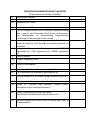
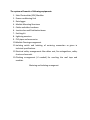
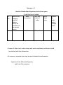
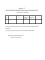
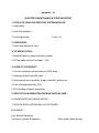
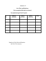
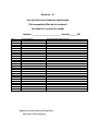
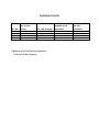
TECHNICAL SPECIFICATIONS
I. DEFINITION
The Grid Connect Solar Power Generating System consists of mainly three
components viz. the solar photovoltaic (SPV) array, module mounting structure
and the power conditioning unit (PCU)/ inverter. The SPV array converts the
solar energy into DC electrical energy. The module mounting structure holds
the modules in required position and the DC electrical energy is converted to
AC power by the PCU, which is connected to the power grid. The AC power
output of the inverter is fed to the AC distribution board through metering
panel and isolation panel. The 415 V AC output-3Ø of the system will be utilized
and after synchronizing with the grid, can be exported to the grid.
II. PV MODULE (S)
1. The PV module used in Grid Connected Solar Power system should have
the latest addition of following IEC-PV Module qualification test or
equivalent BIS Standard
a. IEC 61215 ---- For Modules
b. IEC 61730 ---- For Safety (Part 1 & 2)
c. IEC 61701 --- For corrosion
2. The power output of the module (s) under STC should be as given in
section scope of work. Modules of minimum 150 W output each or
above output should be used. Photo / electrical conversion efficiency of
SPV module shall be greater than 13% under STC
3. All materials used shall have a proven history of reliable and stable
operation in external applications. It shall perform satisfactorily in
relative humidity up to 80% with temperatures between -1 Deg C and
+65 Deg C and with stand gust up to 200km/h from back side of the
panel. The terminal box on the module should have a provision for
opening for replacing the cable, if required.
4. A strip containing the following details should be laminated inside the
module so as to be clearly visible from the front side.
a. Name of the Supplier or distinctive Logo
b. Model or Type No.
c. Serial No.
d. Year of make.
5. The rated output power of any supplied module shall not vary more than
3-5% from the average power rating of all modules.
6. The module frame is made of corrosion resistant materials, which is
electrolytically compatible with the structural material used for
mounting the module.
7. Protective devices against surges at the PV module shall be provided, if
required. Low voltage drop bypass and / or blocking diode(s) may also be
provided, if required.
8. Module Junction box (weather resistant) shall be designed for long life
out door operation in harsh environment.
9. A minimum warranty of 20 (Twenty) years shall be given with
degradation of power generated not exceeding 10% (Ten) over the entire
period of 10 (Ten) years.
10.The solar modules shall have suitable encapsulation and sealing
arrangements to protect the silicon cells from the environment. The
arrangement and the material of encapsulation shall be compatible with
the thermal expansion properties of the Silicon cells and the module
framing arrangement/material. The encapsulation arrangement shall
ensure complete moisture proofing for the entire life of the solar
modules.
11.Each module shall have low iron tempered glass front for strength and
superior light transmission. It shall also have tough multi layered polymer
back sheet for environment protection against moisture and provide
high voltage electrical insulation.
12.The modules and cell must be made in India.
13.Data sheet of the offered module along with their IEC certificate and
third party test results must be submitted along with the offer giving
details of peak power, peak current, short circuit current, fill factor, open
circuit voltage, peak power voltage etc.
Orientation and Tilt of PV Module
Modules alignment and tilt angle shall be calculated to provide the maximum
annual energy output. This shall be decided based on the location of array
installation.
III. EARTHING AND SURGE PROTECTIONS
1. The array structure of the PV modules shall be grounded properly using
adequate numbers of earthing pits. All metal casing/ shielding of the plant
shall be thoroughly grounded to ensure safety of the power plant. All the
power conditioning unit and electricity metering unit having any exposed
metal part must be grounded.
2. All the grounding must be double grounding. There should be a two
separate grounding.
3. The SPV power plant shall be provided with lightning & over voltage
protection. The source of over voltage can be lightning, atmosphere
disturbance etc.
Earthing and lightning protection:
Earthing:
The array structure of the PV yard shall be grounded properly using
adequate number of earthing kits. All metal casing / shielding of the plant
shall be thoroughly grounded to ensure safety of the power plant.
Lightning:
The SPV Power Plant shall be provided with lightning & over voltage
protection. The main aim in this protection shall be to reduce the over
voltage to a tolerable value before it reaches the PV or other sub system
components. The source of over voltage can be lightning, atmosphere
disturbances etc.
Metal oxide variators shall be provided inside the Array Junction Boxes. In
addition suitable MOV’s also shall be provided in the Inverter to protect the
inverter from over voltage.
IV. MECHANICAL COMPONENTS
Metallic frame structure of galvanized steel with stands to be fixed on the
roof of the building to hold the SPV module (s) one foot above roof level. The
inclination angle should be best suitable to get the maximum output. All
hardware, nuts, bolts should be cadmium passivated.
Module mounting structure:
1. The array structure shall be made of hot dip galvanized MS angles of size
not less than 50 mm x 50 mm x 6 mm size. The minimum thickness of
galvanization shall be at least 70 (seventy) microns. All nuts & bolts shall
be made of very good quality ISI grade stainless steel. The minimum
clearance of the lowest part of the module structure and the developed
ground level shall not be less than 500 mm.
2. Leg assembly of module mounting structure made of different diameter
galvanized tubes may be accepted. The work should be completed with
supply, fitting fixing of clamps, saddles, nut & bolts etc. While quoting
the rate, the bidder may mention the design & type of structure offered.
All nuts & bolts shall be made of very good quality stainless steel.
3. The structure shall be designed to allow easy replacement of any module
and shall be in line with site requirements. The structure shall be
designed for simple mechanical and electrical installation. It shall support
SPV modules at a given orientation, absorb and transfer the mechanical
loads to the ground properly. There shall be no requirement of welding
or complex machinery at site.
4. The array structure shall be so designed that it will occupy minimum
space without sacrificing the output from SPV panels at the same time it
will withstand wind speed up to maximum 200 km/h.
5. The supplier/manufacturer shall specify installation details of the PV
modules and the support structures with appropriate diagrams and
drawings.
6. PCC ARRAY FOUNDATION BASE: The legs of the structures made with GI
angles will be fixed and grouted in the PCC foundation columns made
with 1:2:4 cement concrete. The minimum clearance of the lowest part
of any module structure shall not be less 500 mm from ground level.
While making foundation design, due consideration shall be given to
weight of module assembly, maximum wind speed of 200 km/hr and
seismic factors for the site.
7. The bidder can visit the site before quoting rate for civil works. After
taking in to consideration all aspects of the site, roof top strength etc.,
the bidder shall quote for civil works. The foundation design of module
structure design shall be submitted to SMC for approval. The work will
have to be carried out as per designs approved by SMC.
Junction Boxes
1. The junction boxes shall be dust, vermin and waterproof and made of
FRP. The terminals shall be connected to copper bus bar arrangement of
proper sizes. The junction boxes shall have suitable cable entry points
fitted with cable glands of appropriate sizes for both incoming and
outgoing cables. Suitable markings shall be provided on the bus bar for
easy identification and cable ferrules shall be fitted at the cable
termination points for identification. The junction boxes shall have
suitable arrangement for the following:
2. Combine groups of modules into independent charging sub-arrays that
shall be wired to the PCU.
3. Provide a test point for each sub-group for quick fault location.
4. To provide group array isolation.
5. The rating of the JB’s shall be suitable with adequate safety factor to
inter connect the Solar PV array.
DC Distribution Board (DCDB):
Solar array side breaker shall be housed in enclosure. These can also be
housed within the PCU to save space.
V. OTHER FEATURES
i. The PV module (s) will be warranted for a minimum period of 20 years
from the date of supply with maximum 10% degradation in 10 years.
Solar PV power plant will be warranted for a period of ten years from
the date of supply.
ii. An Operation, Instruction and Maintenance Manual in English and
Gujarati should be provided with the system.
2. The following minimum details must be provided in the Manual
a) About Photovoltaic
b) About solar PV system – its components and expected
performance.
c) About PV module
d) Clear instructions about mounting of PV module (s)
e) About electronics
f) DO’s and DONT’s
g) Clear instructions on regular maintenance and trouble shooting of
solar power plant.
h) Name and address of the person or service canter to be contacted
in case of failure or complaint.
VI. The details of the Power Conditioning Unit are as given below:
Inverter of the suitable capacity per location has to be used.
The inverter must comply the following condition
IEC 61683 ----- Inverter Efficiency
IEC 60068 ---- Environmental
IEC 62104 ----- Safety
IEC 61000 ----- EMC
Following are recommended brands of the inverter, however other brands
having matching specifications and test certification can be considered.
Recommended Brands of PCUs (Alphabetically)
ABB
Bonfiglioli
Delta
Helios System
Mitsubishi
Refusol
Schneider
SMA
The output of the inverter must match the Indian Grid system 50 Hz, three
phase.
The PCU must have efficiency greater than 98%.
PCU rating(NOMINAL)
415 V VAC grid interactive output
The power conditioner unit shall convert DC produced
by SPV array and adjust the voltage & frequency levels
to suit the Grid Purpose
The capacity of the PCU per location is as given in the
section ‘scope of work’
Grid supervision
All three phases shall be supervised with respect to rise
/ fall in programmable threshold values of frequency &
the power section of the plant. The plant shall get
disconnected / connected from the grid in case of a grid
fault /after normal grid conditions have resumed. The
grid supervision must comply with VDEW or other
relevant/equivalent regulations
Type & technology
IGBT based. Utilize a circuit topology and components
suitable for meeting the specifications.
Output voltage on
415 +10%, - 15% V AC
ACside
A dedicated isolation transformer housed in the PCU
enclosure shall be supplied to match the PCU output
voltage to the utility grid voltage.
Output voltage
415 V, 50 Hz AC
Output Frequency
50 + 1.5Hz, - 3.5 Hz
DC system voltage
The electrical safety of the array installation is of the
utmost importance. Array electrical configuration shall
be in such way, that, the MPPT shall operate with
maximum efficiency, between the, low and high
temperature of the site.
Maximal Current ripple
5% PP
Power Factor
0.95 inductive to 0.95 capacitive
Ambient temperature
5 to 55 degree Centigrade
Housing Cabinet
1. PCU shall be housed in suitable switch cabinet, with
min IP 21 degree of Ingress Protection.
2. Weatherproof, rodents & insect proof
3. Components and circuit boards mounted inside the
enclosures clearly identified with appropriate
permanent designations, which shall also serve to
identify the items on the supplied drawings.
4. All doors, covers, panels and cable exists shall be
gasketed
2. or otherwise designed to limit the entry of dust and
moisture. All
3. doors shall be equipped with locks. All openings shall
be provided with grills or screens with openings no
larger than 0.95cm (about 3x8 inch).
Electrical safety
The PCU shall include appropriate self protective and self
Protection
General
Diagnostic feature to protect itself and the PV array
from damage in the event of PCU component failure or
from parameters beyond the PCU’s safe operating range
due to internal or external causes. The self-protective
features shall not allow signals from the PCU front panel
to cause the PCU to be operated in a manner that may
be unsafe or damaging. Faults due to malfunctioning
within the PCU, including commutation failure, shall be
cleared by the PCU protective devices and not by the
existing site utility grid service circuit breaker.
1. Mains (Grid) over-under
voltage and frequency
protection.
2. Over voltage protection against
atmospheric lightning
2. Protection against voltage fluctuations in the grid
itself and internal faults in the power conditioner,
operational errors and switching transients.
Over/ Under voltage
Against ISLANDING.
Note: MOV type surge arrestors on AC and DC terminals
for over voltage protection from lightning-induced
surges
Full protection against accidental open circuit and
reverse polarity at the input.
Full Protection
Inbuilt protection for internal faults including excess
temperature, commutation failure, overload and cooling
fan failure is obligatory Galvanic isolation is provided to
avoid any DC component being injected into the grid
and the potential for AC components appearing in the
array.
Accidental open Circuit
An integrated earth fault detection device is provided to
detect eventual earth fault on DC side
Internal faults
Disconnection of the PV generator in the event of loss
of the main grid supply is achieved by in built protection
within the power conditioner. This may be achieved
through rate of change of current, phase angle,
unbalanced voltages, or reactive load variants.
Galvanic Isolation
Operation outside the limits of power quality as
described in technical data sheet shall cause the power
conditioner to Disconnect the grid. Additional
parameters requiring automatic disconnection are:
1. Neutral voltage displacement
2. Over current
3. Earth fault &
4. Reverse power
Earth fault supervision
Disconnection and
In each of the above cases, tripping time shall be less
islanding
than 0.5 seconds. Response time in case of grid failure
due to switch off or failure based shutdown should be
well within 60 seconds. PCU has facility to reconnect the
Inverter automatically to the grid following restoration
of grid, subsequent to grid failure condition
Automatic reconnection
after the Grid failure is
restored
Array Tracking
Included authentic tracking of the Solar array’s
maximum power operation voltage (MPPT)
Array Ground fault
Provided
Operator interface
LCD and key pad operator interface are provided
Fault Conditions
Automatic fault conditions reset for all the parameters
like
voltage, frequency and / or black out
Control Logic failure
Via watch dog timers
detection
Parameter access
All parameters accessible through an industry standard
communication link.
DC–AC Conversion
93 % output ranging from 20% to full load. Idling current
efficiency
at no load shall not exceed 2% of the full load current.
DC Isolation
Provided at the output by means of a suitable isolating
transformer
Parallel operation with
Provided and capable of interrupting
Grid
line to line currents and
line to ground faults currents.
Unbalanced output load
PCU is able to withstand and unbalanced output load to
the extent of 30%.
Shut down and stand by
Shut down / standby mode with its contact open under
mode
the following conditions before attempting an automatic
restart after an appropriate time delay; in sufficient
solar power output.
a) Insufficient solar power input:
When the power
available from the PV array is insufficient to supply the
losses of the PCU, the PCU shall go to a
standby/shutdown mode.
The PCU control shall prevent excessive cycling during
rightly shut down or extended periods of insufficient
solar radiation.
b) Utility -Grid over or under voltage :
The PCU
shall restart after an over or under voltage shutdown
when the utility grid voltage has returned to within
limits for a minimum of two minutes.
c) Utility-Grid over or under frequency : The PCU shall
restart after an over or under frequency shutdown when
the utility grid voltage has returned to the within limits
for minimum of two minutes.
PCU generated
Shall not exceed a total harmonic current distortion of
harmonics.
5%, a single frequency current distortion of 3% and
single frequency current distortion of 1%, when the first
through the fiftieth integer harmonics of 50 Hz are
considered.
Circuit separation
High voltage& power circuits separated from low
voltage and control circuits.
Special Features
PCU must have a single phasing protection with auto
islanding.
PCU must be totally isolated (except for minor grid
detection circuit) during non production of energy.
PCU must have power factor correction.
PCU should have the KVAR import export less than 5%
Internal wiring
Standard CU wiring, with flame resistant insulation
Cabling Practice
a) Cables: PVC Cu cables as per relevant international
Standards
b) Cable connections : suitable terminations
c) PVC channel with covers to house the cables
High Voltage test
PCU with stand high voltage test of 2000 Vrms between
either the input or the output terminals and the cabinet
(chassis).
EMI (Electromagnetic
PCU shall not produce EMI which cause malfunctioning
interface)
of electronic & electrical instruments including
communication Equipments which are located within
the facility in which the PCU is housed.
Display on front panel
a) instantaneous PCU ac power output and the DC
and indicators
voltage current and power input
b) Accuracy of display: 3% of full scale factor or better
c) Display visible from outside the PCU enclosure.
d) Operational status of the PCU, alarms, trouble
indicators and AC and DC disconnect switch positions
shall also be Communicated by appropriate messages or
indicator lights on the front cover of the PCU enclosure.
Emergency off
Emergency off button is located at an appropriate
position on the unit
Grounding
PCU includes ground lugs for equipment and PV array
groundings.
Exposed surfaces
The DC circuit ground is a solid single point ground
connection.
Exposed surfaces of ferrous parts are thoroughly
cleaned, primed, and painted and suitably protected to
survive a nominal 30 years design life of the unit.
Factory testing
a) Tested to demonstrate operation of its control system
and the ability to be automatically synchronized and
connected in parallel
with a utility service, prior to its shipment.
b) Operation of all controls, protective and
instrumentation circuits demonstrated by direct test if
feasible or by simulation operation conditions for all
parameters that can not be directly tested.
c) Demonstration of utility service interface protection
circuits and
functions, including calibration and functional trip tests
of faults and isolation protection equipment.
d) Operation of start up , disconnect and shutdown
controls also to be tested and demonstrated, stable
operation of the PCU and response to control signals
shall also be tested and demonstrated.
e) Factory testing includes measurement of phase
currents, efficiencies, harmonic content and power
factor. All tests shall be performed 25, 50, 75 and 50% of
the rated nominal power.
f) Factory test report (FTR) : Should be supplied with the
unit after all tests. The FTR shall include detailed
description of all parameters tested qualified and
warranted.
Operating modes
a) Night or sleep mode : where the Inverter is almost
completely turned off, with just the timer and control
system still in operation, losses < 2 W per 5 kW
b) Standby mode: where the control system
continuously
Monitors the output of the solar generator until pre-set
value is exceeded (typically 10 W). Operational of MPP
tracking mode: the control system continuously adjust
the voltage of the generator to optimize the power
available. The power conditioner shall automatically re-
enter standby mode input power reduces below the
standby mode threshold. Front panel display providing
the status of the PCU, including AC power output & DC
current voltage and power input, and unit fault
indication
Inverter / Array size
The ratio of the Inverter continuous power rating and
ratio
the array peak power rating shall be between 80 to 90%
or any other value found suitable. This is because better
overall annual yield can be obtained by allowing the
Inverter to operate for longer periods closer to optimal
efficiency. Inverter efficiency should exceed 90% except
when operating at less than 10% of maximum output
MPPT
Maximum power point tracker is integrated in the
power conditioner unit to maximize energy drawn from
the array. The MPPT shall be micro processor based to
minimize power losses. The MPPT shall have provision
(manual setting) for constant voltage operation.
Metering
a)
PV array energy production: Meter to log the
actual amount of AC energy generated / consumed by
the PV system shall have to be provided
b)
Solar irradiance: An integrating pyranometer
(Class II or better) to be provided, with the sensor
mounted in the plane of the array. Readout shall be
integrated with data logging
Data logging
a) All major parameters available on the digital bus and
logging facility for energy auditing through the internal
microprocessor and can be read on the digital front
panel at any time the current values, previous values for
up to a month and the average values.
The following parameters shall be accessible via the
operating interface display :
AC voltage
AC output current
Output power
DC input voltage
DC input current
Time active
Time disabled
Time Idle
temperatures (C)
Converter status
Protective function limits (i.e AC over voltage, AC under
voltage,
Over frequency, under frequency, ground fault, PV
Starting voltage, PV stopping voltage, over voltage
delay, under voltage delay over frequency, ground fault
delay, PV starting delay, PV stopping delay.
VI. The details of the CABLES & ACCESSORIES
All the cables that shall be supplied shall be conforming to IS 1554 / 694 Part 1
of 1988. The size of the cables between array interconnections, array to
junction boxes, junction boxes to PCU etc shall be so selected to keep the
voltage drop and losses to the minimum.
The cables must have following minimum specifications:
XLPO 1200C insulation class.
Insulation against Ultra Voilet, Water, Ozone, Fluid, oil, Salt and General
weather.
Protection against Rodent, Fire
Halogen Free, Frame Retardant and low smoke emission
Fire Retardant to meet IEC-607541-1 / EN-50268-2
RoHS compliant
Maximum temperature to meet is 1200C (20,000 Hr)
Voltage Resistance Test as per EN 50395
Maximum Voltage: 1,000 V AC or 1,800 V DC
Short Circuit Temperature 2800C
Conductor must be Annealed Tinned Copper as per IEC 60228 Class V
Following are recommended brands of cables, however other brands having
matching specifications and test certification can be considered.
Recommended Brands of Cables (Alphabetically)
Finolex
Havel
JRD Cables
Polycab
Siechem
Yogicab insulations
VII Metering and Connection to Grid.
Separate meter, cable connections are needed for power plant and existing
connection. Isolation switch along with necessary cables have to be provided
by the contractor.
VIII CONTROL ROOM
If required, bidder can construct control room at no additional cost.
IX SPARE PARTS
One set of essential spares for the PCU shall be provided and made available at
each location.
X DOCUMENTATION
Two sets of installation manual / user manual shall be supplied along with the
each power plant. The manual shall include complete system details such as
array lay out, schematic of the system, inverter details, working principle etc.
Step by step maintenance and troubleshooting procedures shall be given in the
manuals.
XI BILL OF MATERIAL
The bidder should provide the bill of material for each location grid connect
SPV power plant mentioning the quantity of each of the item consisting in the
system, along with the offer.
XII Health, Safety & Environment
The bidder shall submit the following before starting the installation of the
power plant.
Safety and Environment policy of the Company
HSE Manuals for Installation
Emergency Management Plan
XIII Experience of the Bidder
A comprehensive list of past projects implemented, by the bidder
(manufacturer) indicating clients, dates, size of projects and any other relevant
material should be included in the offer.
XIV Documentation
Two sets of installation manual / user manual shall be supplied along with the
each power plant. The manual shall include complete system details such as
array lay out, schematic of the system, inverter details, working principle etc.
Step by step maintenance and troubleshooting procedures shall be given in the
manuals.
Request for Selection of bidders for implementation of Grid
Connected Rooftop Solar Power Plant in steps of 500 KWp in
Osmanabad
Osmanabad town in the Marathwada region of Maharashtra enjoys over 300 sunny
days in a year and an average solar insolation of 5.5 kWh/m2/day. Operational solar
plants in this region have given an output of over 15 million units per MWp in a 12
month period. MAHAGENCO is in the process of establishing a 50 MWp PV based
solar power generation plant in this region
Osmanabad Municipal Council invites offers from interested parties for setting up Grid
Connected Rooftop power plants as part of second phase of the Jawaharlal Nehru
National Solar Mission as per guidelines issued by the Ministry of New and Renewable
Energy , Government of India on 26/6/2014.
( Ref. http://mnre.gov.in/filemanager/UserFiles/Scheme-Grid-Connected-Rooftop-&-small-solar-power-plants.pdf )
The proposal should include preparation of Detailed Project Report in a project mode as
envisaged for systems larger than 50 kWp, setting up of systems and Operation &
Maintenance (O&M) for 25 years. The bidder has to supply, install, commission,
operate and maintain the Solar PV Systems at their own cost throughout the agreement
period of 25 years. The project cost and the return of investment as per CERC
guidelines is to be recovered by the sale of solar energy generated by the rooftop solar
PV systems. The business model considered should be of solar installations owned,
operated & maintained by third party as per section 7.0 (b) i & ii of the operational
guidelines of the scheme .Tariffs will be decided by MERC / MAHADISCOM as per
section 8 ii).
Osmanabad town has over 20000 dwellings (households/ buildings) and approximately
10 million sq feet of roof top. Initially the Council acting as implementing agency of the
scheme proposes to cover approximately 1000 dwellings of an average 1000 sq feet
rooftop amounting to approximately 4 MWp of power generation, in steps of 500 KWp.
Bidder should quote rates per Wp, minimum lease per sq ft per month, probable yearly
generation as well as minimum tariff per unit generated expected by the bidder.
1
1a
1b
1c
2
GENERATION INFORMATION ABOUT THE BIDDER
(To be completely filled by the bidder)
Name of the Company
Postal Address
Telephone nos. Fax no.
5
6a
e-mail address & URL
Type of Company Attach Proof of Company Registration along
with a copy of the Partnership Deed/ Article of Association
and Memorandum of Understanding Proprietorship/
Partnership/ Private Limited/ Public Limited
Name and designation of the representative of the Bidder to
whom all reference shall be made to expedite technical coordination
Entrepreneur Memorandum Part 2 registration with DIC/NSIC
registration no./ CSPO registration no./ DGS&D registration
no.
Factory Address
Factory Telephone/Fax no.
6b
Factory e-mail address
6c
6d
Floor area of the factory Manufacturing facilities
List of machinery be attached as per annexure-VI)
7
Name and address of the Indian/Foreign collaborator(s)if any
8
9a
Joint Venture or Consortium will not be allowed
Details of Technical Staff available. (Please
information as per Enclosed Annexure II)
9b
Details of workmen on muster roll Skilled/
semi-skilled/ unskilled (attach copy of muster roll)
10
Has the company/firm to pay arrear of income tax? If yes up
to what amount.
3
4
furnish
11
Turnover of company for last 3 years 2009-10, 2010-11, 201112 and profit for each year. (with Annual Accounts)
12
Has any Govt. Dept. / Under-taking ever debarred
the company/ firm from executing any work?
2009-10 `. __
2010-11 `. __
2011-12 `. __
It is certified that the information provided above is true to the best of my
knowledge and belief. If any information found to be concealed, suppressed or
incorrect at later date, our tender shall be liable to rejected and our company
debarred from executing any business with OMC.
Sign. & Stamp of the Bidder
Date:
Town Engineer
Osmanabad Municipal Council
The system will consist of following equipments:
1. Solar Photovoltaic (SPV) Modules
2. Power conditioning Unit
3. Data logger
4. Module Mounting Structures
5. Cables and other hardware
6. Junction box and Distribution boxes
7. Earthing kit
8. Lightning arrestors
9. PVC pipes and accessories
10.Module Cleaning arrangement
11.Isolating switch and Isolating of metering connection as given in
technical specifications.
12.Electrical safety arrangements like rubber mat, fire extinguishers, safety
charts and manuals.
13.Climbing arrangement (if needed) for reaching the roof tops and
modules.
Metering and isolating arrangment
Annexure
DEVIATION SHEET
Any deviations offered from the terms and conditions of the Offer should be
clearly specified below in this sheet. If there are no deviations offered, it should
be clearly mentioned on this page.
Deviation offered to Chapter
No. of the tender document
No, Clause
Signature of the Authorized Signatory
and Seal of the company:
Deviation offered
Annexure – II
Details of Similar Work Experience in last three years
Sr.
No
Name of the
Company
,with full
address,
phone, fax
and name of
the contact
person
(To be filled by the bidder)
Work
Ref. and
Description
date of
order
Work
Order
value
Details
of
order
and its
Configu
ration
• Copies of Major work orders along with work completion certificates should
be attached with this information.
• If necessary, separate sheet may be used to submit the information.
Signature of the Authorized Signatory
and Seal of the company:
Annexure – III
Details of Technical Staff available with the company for execution of work.
(To be filled in by the bidder)
Sr
No.
Name
Qualificati
on
Additional
Certificatio
n, if any
Total
experienc
e
Remark
s
• Copies of resumes and appropriate certifications should be attached with this
information
• If necessary, separate sheet may be used to submit the information
Signature of the Authorized Signatory
and Seal of the company:
Annexure – IV
QUARTERLY MAINTENANCE & SERVICING REPORT
1. DETAILS OF SOLAR PHOTOVOLTAIC SYSTEM INSTALLED
1. Supplied by :
2. Date of installation :
3. Servicing period :
From : To:
2. USER PROFILE
1. Name and address of User :
3. TECHNICAL DETAILS
1. Module Capacity, make and serial number :
2. DC fan make and serial number : N/A
4. CHECK OF THE PRODUCT
1. Correct inclination and orientation of SPV panel :
2. Cleaning of dust from SPV panel
:
3. Interconnection of modules, charge controller, battery etc. :
4. Fuse of charge controller, PCU :
5. PCU Reading of power generation :
5. DIFFICULTIES IN OPERATION/ PROBLEM FACED BY USER :
6. DIAGNOSIS DETAILS/ REPAIR ACTION :
7. DATE ON WHICH SYSTEM WAS LAST ATTENDED :
8. REMARKS :
User Name & Signature
Technician’s Name & Signature
Date: (with rubber stamp)
Annexure – V
List of Plant and Machinery
(To be completely filled by the tendered)
For manufacturing of Solar PV panels
Sr.
No.
Name of
equipment
Date of
purchase
Signature of the Authorized Signatory
and Seal of the company:
Date of
calibration
Utility
Annexure – VI
Year wise Electricity Production Confirmation
(To be completely filled by the tendered)
One Sheet Per Location (if needed)
Location : _________________________ Capacity ______ kW
Year
1
2
3
4
5
6
7
8
9
10
11
12
13
14
15
16
17
18
19
20
21
22
23
24
25
Capacity Utilization
Guaranteed kWHr produced per year
TOTAL
Signature of the Authorized Signatory
and Seal of the company:
PART – II
FINANCIAL BID
• Rates quoted by bidder will be for destination. Prices inclusive of taxes, levies,
duties, packing, forwarding, freight, insurance, loading unloading, supply,
installation, commissioning, and any/ all charges for successful Supply &
Installation of the system.
• The rates quoted by the bidder will be excluding Service Tax but inclusive of,
Work Contract Tax, VAT or any other taxes applicable to such work. Any
escalation in such taxes/ levies during the tenure of the contract/ order will
not be paid by OMC and bidders are advised to take in to consideration any
such escalations in the prevailing taxes/levies/duties.
The applicable service tax will be reimbursed on actuals after producing a
valid proof of service tax payment to the competent authority.
• In no circumstances, escalation in the prices will be entertained.
• Your rates are submitted as per the enclosed Performa of schedule of rates.
SCHEDULE OF RATES
,
Sr. No.
minimum lease
per sq ft per
month
Per
Wp charges
(25 years add)
1
Signature of the Authorized Signatory:
And seal of the company:
probable yearly
generation
minimum tariff
per unit
generated