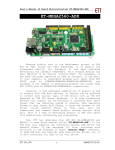
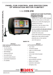
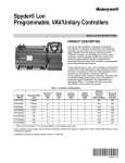
1
FLEC AIR PUMP
1001
Operators Manual
JULY 2009
www.markes.com
QUI-1030
VERSION 1.2
Markes International Ltd.
T: +44 (0) 1443 230935
F: +44 (0) 1443 231531
E: enquiries@markes.com
FLEC Air Pump 1001 User Manual
Markes International
www.markes.com
This page left intentionally blank
QUI-1030 V 1.2 July 09
Markes International Ltd.
T: +44 (0) 1443 230935
F: +44 (0) 1443 231531
E: enquiries@markes.com
FLEC Air Pump 1001 User Manual
Markes International
FLEC AIR PUMP 1001 Operators’ Manual
Contents
1. Introduction
4
2. Operating instructions
5
2.1. Operating modes
5
2.1.1. SET Mode
5
2.1.2. RUN Mode
5
2.1.3. EXTERNAL Mode
5
2.2. Pump 1001 Calibration program
5
2.2.1. Software set up
7
2.2.1.1. Flow Calibration procedures
8
2.3. Adjusting the pump
12
3. Specifications
14
List of Figures
Figure 1.
Figure 2.
Schematic of FLEC pump showing connections and buttons
4
The pump calibration window
7
Flow calibration window
9
Figure 3.
Non-linear flow sensor calibration curve (black) and Pump 1001
6
linear calibration covering flw range a-b (blue)
Selecting the Comport
7
Figure 5.
The calibration and settings window
Figure 4.
Figure 6.
Figure 7.
9
Calibration graph produced by flow calibration wizard
11
Establishing the low calibration point
Figure 10.
Accepting the calibration
Figure 11.
Check and adjust function
QUI-1030 V 1.2 July 09
Markes International Ltd.
10
11
13
-3T: +44 (0) 1443 230935
F: +44 (0) 1443 231531
E: enquiries@markes.com
www.markes.com
Flow Calibration Wizard
Figure 8.
Figure 9.
8
FLEC Air Pump 1001 User Manual
Markes International
1. Introduction
The FLEC air pump 1001 (figure 1) was developed in response to the special
requirements of the Field and Laboratory Emission Cell (FLEC) 1. However, it is
equally applicable to any air-sampling or air-metering application within its flow
range.
PWR
Display
MODE
UP
SET
DOWN
Sensor socket
Chemanet
socket
Needle valve
Power Supply
Air in
Figure 1: Schematic of FLEC pump showing connections and buttons
The FLEC applications require an adjustable well regulated constant and pulseless
air flow on both the suction and the pressure side of the pump. Therefore the FLEC
air pump 1001 is based on a rotating displacement pump unit augmented by a
pulse damping unit, and regulated by a microprocessor based servo-mechanism
that takes its signal from a highly accurate and sensitive mass flow sensor.
The pump unit contains a microprocessor and memory to read AD-converter values
from the flow, temperature and humidity measuring circuits and to calculate and
display the flow, temperature and humidity using linear calibrations stored in the
memory.
The pump comes factory calibrated for flow (mL/min), temperature (°C) and
relative humidity (% RH). However, other and/or more accurate flow calibrations
over a different or narrower flow range can be obtained by using the optional
pump 1001 calibration program (see section 2).
QUI-1030 V 1.2 July 09
Markes International Ltd.
-4T: +44 (0) 1443 230935
F: +44 (0) 1443 231531
E: enquiries@markes.com
www.markes.com
Many FLEC applications require the temperature and humidity of the air passed
through the FLEC cell to be determined. Therefore, the pump can also determine
the temperature and relative humidity using an external dual sensor electrically
connected to the pump and with provisions for inserting the sensor into the air
stream where required.
FLEC Air Pump 1001 User Manual
Markes International
2. Operating instructions
Connect the 12 Volt DC power supply to your mains and to the Power supply socket
(rectangular with 2 pins) in the upper right corner of the connection plate.
Turn the pump on by pressing the PWR button, and holding it down. While pressing the
button the display shows the name of the pump e.g. Air Pump 1001-A. When the button
is released the display shows the serial number and the pump ID.
To turn the pump off, press and hold the PWR button. The display initially reads “Power
Off” followed by a series of dashes (- - - -). At this point, the pump is turned off and the
button can be released.
The delay is present to prevent accidental shutting down of the pump.
2.1. Operating modes
The pump has 3 modes of operation:
1. Settings mode (SET MODE)
2. Running mode (RUN MODE)
3. Chemanet communication mode (EXTERNAL MODE)
2.1.1. SET Mode
In SET MODE, (MODE entered when you power on the pump), the pump can be
programmed to:
a. Wait for a delay time with flow = 0 (1st setting, “del”)
b. Run for a set run time with the set flow (2nd setting, “run time”)
c. Repeat a and b a set number of times (3rd setting, “cycles”)
d. Run at a specified flow
In order to store and keep new values entered in the pump manually in SET mode, the
pump must be changed to run mode or external mode before switching off.
2.1.2. RUN Mode
In RUN MODE the pump executes the program entered in the SET MODE (the Settings).
It is possible to read the current flow, temperature and humidity from the pumps display
in the RUN MODE.
In EXTERNAL mode the pump can communicate with a PC over a serial network - the
CHEMANET. The pump can be completely controlled from a PC in the EXTERNAL MODE.
This mode is used to calibrate the flow, temperature and humidity measurements for a
given pump-sensor combination, and to change the settings (Flow, Delay Time, Run
Time and Cycles) used in RUN mode. Therefore, whereas there are two mechanisms for
entering the settings (via the software or directly on the pump) the pump can only be
calibrated from a PC over the CHEMANET with the pump in EXTERNAL MODE.
2.2. Pump 1001 Calibration program
The purpose of the program is to prepare the pump for standalone operation and
document the calibration and settings used for this operation.
QUI-1030 V 1.2 July 09
Markes International Ltd.
-5T: +44 (0) 1443 230935
F: +44 (0) 1443 231531
E: enquiries@markes.com
www.markes.com
2.1.3. EXTERNAL Mode
FLEC Air Pump 1001 User Manual
Markes International
The program can:
• Calibrate the flow, temperature and humidity measurements for a given pumpsensor combination.
• Change settings (Flow, Delay Time, Run Time and Cycles) used in RUN MODE.
• Store calibrations and settings in the pumps memory (for use in stand-alone
operation).
• Save calibration and settings to disk files for later retrieval.
• Read the calibration and settings data from the pumps memory.
• Change the Name and the ID of the pump.
• Make reports of the calibration data and settings in the pumps memory for onscreen viewing, printing, or exporting to file for importing into other programs.
• Check and adjust the pump
High calibration point
Mass flow sensor output curve
Low calibration point
Calibration line covering flow
range a - b
a
b
Figure 2: Non-linear flow sensor calibration curve (black) and Pump 1001
linear calibration covering flow range a - b (blue)
QUI-1030 V 1.2 July 09
Markes International Ltd.
-6T: +44 (0) 1443 230935
F: +44 (0) 1443 231531
E: enquiries@markes.com
www.markes.com
Flow sensor output (AD-value)
Note: It is very important to calibrate the flow sensor around and close to the flow at
which it will operate because a calibration curve made over the entire flow range 0 to
1000 ml/min is not linear (as shown in Figure 2). The pump contains one calibration line
covering a specified part range of the complete flow range of the pump. If the pump is
to operate outside this part-range the calibration line in the pump must be changed to
one whose part-range covers the desired flow value. The pump is precalibrated using a
50 and 100 mL/min flow with a deviation of 1.5 mL/min. It is not recommended to go
below 40 mL/min and above 130 mL/min without additional calibration.
FLEC Air Pump 1001 User Manual
Markes International
Using the calibration program the pump can be calibrated to any required accuracy
within the resolution of the AD converter (± 1AD unit) using a narrow flow interval.
Each of the three measuring circuits (for flow, temperature and humidity) delivers its
measured result to an AD converter (Analog to Digital), which is a voltmeter that can be
read (digitally) by the processor in the pump. The voltmeter measures voltages from 0
to 4.095 V with a resolution of 1 mV (0.001 Volt). Calibration establishes what real
value (flow in ml/min, temperature in °C or humidity in % RH) corresponds to a given
AD converter voltage (AD value) read from the corresponding AD converter, and reports
this real value.
2.2.1. Software set up
• Download software onto PC (“Release” folder, Pump 1001 Calibration program)
• Connect pump to PC via Chemanet cable, into comport 1, 2, 3 or 4
• Open FLEC AIR PUMP 1001 Calibration program
• Go to <Options> and <Select comport>:
Figure 3: Selecting the Comport
• Select the comport number and press <OK>
• Switch on the pump by pressing the PWR button, and then hold down the “M”
key until EXTERNAL MODE is displayed.
• Go to options select pump (scans network for pump).
• The pump calibration window should now be open displaying the air pump and
serial number:
QUI-1030 V 1.2 July 09
Markes International Ltd.
-7T: +44 (0) 1443 230935
F: +44 (0) 1443 231531
E: enquiries@markes.com
www.markes.com
Figure 4: The pump calibration window
FLEC Air Pump 1001 User Manual
Markes International
The serial number (Serial No.) is the hardware identification of the individual physical
pumps and is set by the factory and cannot be changed.
The PumpID (Address No.) serves to identify the pump on the CHEMANET network. No
two pumps on a network can have the same PumpID. An important function of this
program is to change duplicate PumpIDs.
The Name (Name) is a user identification that can be changed and used as best suited
for the purpose of the pump. Use it to identify the pump by position or function in the
application in which it takes part. The pump name also appears in the reports.
2.2.1.1. Flow Calibration procedures
• Install a reference flow meter to the pump outlet and a reference sample tube
to the pump inlet prior to calibration.
• From the menu select <Functions> followed by <Calibrations and settings>.
The calibration and settings window should now be opened:
Figure 5: The calibration and settings window
This is where the operations on the individual pumps maybe performed i.e. changing
their Identification, Settings, Calibrations, and from where the pumps are checked
and adjusted.
• Initiate a flow calibration by clicking in the flow ref. (High or Low). This opens
the flow calibration window:
QUI-1030 V 1.2 July 09
Markes International Ltd.
-8T: +44 (0) 1443 230935
F: +44 (0) 1443 231531
E: enquiries@markes.com
www.markes.com
A two point calibration is used. To get the best calibration of the flow make reference
set points close to the flows you are going to use, do not make reference set points
differ more than 100 mL/min.
FLEC Air Pump 1001 User Manual
Markes International
Figure 6: Flow calibration window
• Select <Linear Calibration Wizard>. This opens the calibration wizard which
consists of 4 steps:
• Select <Next> to get to the second wizard page where the low calibration
point is established:
QUI-1030 V 1.2 July 09
Markes International Ltd.
-9T: +44 (0) 1443 230935
F: +44 (0) 1443 231531
E: enquiries@markes.com
www.markes.com
Figure 7: Flow Calibration Wizard
FLEC Air Pump 1001 User Manual
Markes International
Figure 8: Establishing the low calibration point
The graph shows the ‘continuously’ measured AD value from the flow sensor. This is
used to determine the stability of the flow:
• To make the pump produce the flow itself drag the black vertical handle in the
SetServo control below the graph or write the AD value you want the servo
mechanism to keep in the SetServo field - the value only takes effect when you
leave the field by clicking outside or press the tab key. Having established the
flow, you have to measure it using an external flowmeter attached to the Air
outlet and enter the value you read from the external flowmeter in the field
<Low Flow ml/min>.
• Adjust the needle valve on the side of the pump to increase the flow
resistance, and obtain a more stable flow (less noisy).
Note: Care should be taken not to overtighten the valve and subsequently
work the pump too hard (See section 2.3)
• When the standard deviation of five measurements is less than 1% of the
measured mean, the <Next> button becomes available
• Once this is complete select <Next>, which shows a graph of the calibration
as produced by the wizard:
QUI-1030 V 1.2 July 09
Markes International Ltd.
-10T: +44 (0) 1443 230935
F: +44 (0) 1443 231531
E: enquiries@markes.com
www.markes.com
• Select <Next> to establish the high calibration point and repeat the
procedures as for the low calibration point
FLEC Air Pump 1001 User Manual
Markes International
Figure 9: Calibration graph produced by flow calibration wizard
• Select <OK> and the calibration window is displayed with two linear
calibrations on the graph with the option to either accept the wizard calibration
as the current calibration, or to keep the current calibration.
www.markes.com
Figure 10: Accepting the calibration
QUI-1030 V 1.2 July 09
Markes International Ltd.
-11T: +44 (0) 1443 230935
F: +44 (0) 1443 231531
E: enquiries@markes.com
FLEC Air Pump 1001 User Manual
Markes International
Note: The calibration steps described above only change the calibration data in PCmemory. To make them effective in the pump when operated as a stand-alone unit
(i.e. to change them in the pump’s memory), you must save them to the pump using
menu <File/Calibration/Save to pump>.
Additionally, when the current pump is changed, the program will compare the data
in PC-memory to the data in the pump and there will be an option to either save the
now current data in the PC-memory to the pump, or revert to what is in the pump’s
memory.
2.3. Adjusting the pump
When the pump is operating at a low “speed”, either because the SET flow is low or
because the resistance to the airflow is low (or both), the servo mechanism becomes
unstable and the flow pulsates. This can be heard in the pitch of the motor. To stabilise
the flow increase the speed of the motor by increasing the resistance to the flow
(described below).
Furthermore, when the pump is operating at a high “speed”, the resistance to airflow
can be too high and the speed of motor should be decreased. This is done by decreasing
the resistance to airflow.
Note: The resistance to the airflow is very important to the correct operation of the
pump, therefore it is vital to check the speed of the motor at the SET flow required with
any external resistance e.g. the sorbent tube, in line.
Note: that different sorbent tubes (i.e. packed with different sorbent(s)) will have
different resistances.
In order to change the resistance adjust the needle valve (see figure 1).
Note: It is vital not to overtighten the needle valve. It should only be used when a
moderate increase in flow resistance is needed to get a stable flow.
To check and adjust the flow, use the “Check and Adjust” function in the Calibration
program. This can be used to:
a. Check that you actually get the flow you have preset in the operating
environment.
b. Adjust the flow resistance (needle valve on the pump) so that you get a
pulseless flow at the preset value, in the actual the operating environment.
c. Check the temperature and humidity measured by the sensor.
• From the calibrations and settings window select <Functions> followed by <Check
and adjust pump>. This opens the check pump window:
Markes International Ltd.
www.markes.com
QUI-1030 V 1.2 July 09
-12T: +44 (0) 1443 230935
F: +44 (0) 1443 231531
E: enquiries@markes.com
FLEC Air Pump 1001 User Manual
Markes International
Figure 11: Check and adjust function
This gives an interactive graphic picture of the flow and any variations in flow, and their
amplitudes are displayed.
• Enter the flow at which the pump will be operating in the field <ServoGoal>. The
pump will then start the servo mechanism to maintain the flow at the specified value.
• The blue curve shows the individual measurements, and the red curve shows the
current mean value of the last <Points in mean> number of measurements.
• Adjust the needle valve on the side of the pump to increase the flow resistance,
and obtain a more stable flow (less noisy).
• The graph, and the mean and individual values together with the current values,
shown above the graph, check whether the pump is actually delivering the flow
required.
Note: for further and more detailed information on the calibration of the FLEC pump
please refer to the <Help> function in the menu.
Markes International Ltd.
www.markes.com
QUI-1030 V 1.2 July 09
-13T: +44 (0) 1443 230935
F: +44 (0) 1443 231531
E: enquiries@markes.com
FLEC Air Pump 1001 User Manual
Markes International
3. Specifications
FLEC Air Pump
1001
Part no. FL-1001
Pump Type
Sealed, oil free, rotary displacement pump controlled by a
microbridge mass airflow sensor.
Weight
400 g
Casing
Aluminium and POM, 130 x 40 x 60 mm
Connections
¼” tubings
Flow
0 – 999.9 ml/min
Pressure
Max allowed continuous pressure differential across the
rotating displacement unit is 100 mbar.
Temperature
4 – 50 °C
Humidity
0 – 95% RH
Calibration
Users flow range is determined by calibration range within
the 0 to 1000 ml/min. Normal factory calibration is from
50 to 100 ml/min.
Accuracy
Depends on calibration, calibration range and absolute size
of flow. Flows lower than 4 ml/min are not recommended,
since the measurement resolution alone at this low flow
amounts to 2 –3%. When calibrated at 50 and 100
ml/min, accuracy is from 0.5% at the calibration points to
a maximum of ca 2% between these.
Power
12 V DC/200 mA power supply required.
Markes International Ltd.
www.markes.com
QUI-1030 V 1.2 July 09
-14T: +44 (0) 1443 230935
F: +44 (0) 1443 231531
E: enquiries@markes.com