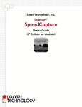
1
The 1st Electronic BAF-scope / Dendrometer
User’s Manual
3rd Edition
LTI Criterion RD 1000 User’s Manual
Third Edition Part Number 0144759
Copyright Notice:
Information in this document is subject to change without notice and does not
represent a commitment on the part of Laser Technology Inc. No part of this
manual may be reproduced in any form or by any means, electronic or mechanical,
including photocopying, recording, or information storage and retrieval systems,
for any purpose other than the purchaser's personal use, without the express written
consent of Laser Technology, Inc.
Copyright © Laser Technology, Inc., 2005. All rights reserved.
First Edition:
June 2005
Second Edition:
June 2005
Third Edition:
May 2006
Patents:
This product is covered by pending patent applications and/or the following
issued U.S. Patent: 6,738,148
Trademarks:
Criterion, Impulse, and TruPulse are trademarks of Laser Technology, Inc.
All other trademarks are the property of their respective owner.
LTI Contact Information:
Laser Technology, Inc.
7070 S. Tucson Way
Centennial, CO 80112 USA
Phone:
Fax:
Web Site:
Email:
1-303-649-1000
1-800-790-7364 (USA and Canada)
1-303-649-9710
www.lasertech.com
service@lasertech.com
Criterion RD 1000 Reference Information:
Record information about your RD 1000 in the table below.
Serial
Number
Firmware
Revision
Number
Magnification
Constant
You can find this value:
On the serial number sticker affixed to
the RD 1000.
When unit is turned ON.
See page 12 for more information.
On the sticker affixed to the Magnifier.
See page 16 for more information.
Value
Criterion RD 1000 User’s Manual Table of Contents
Page 1
Criterion RD 1000 User’s Manual
Table of Contents
Section 1 - Introducing the Criterion RD 1000 . . . . . . . . . . . . . . . . . . .
Features . . . . . . . . . . . . . . . . . . . . . . . . . . . . . . . . . . . . . . . . . . . . . . . . . .
Measurement Types . . . . . . . . . . . . . . . . . . . . . . . . . . . . . . . . . . . . . . . .
Unpacking your RD 1000 . . . . . . . . . . . . . . . . . . . . . . . . . . . . . . . . . . . . .
Views of the RD 1000 . . . . . . . . . . . . . . . . . . . . . . . . . . . . . . . . . . . . . . .
3
3
3
4
4
Section 2 - Quick Start . . . . . . . . . . . . . . . . . . . . . . . . . . . . . . . . . . . . . .
5
Section 3 - Basic Operations . . . . . . . . . . . . . . . . . . . . . . . . . . . . . . . .
Batteries . . . . . . . . . . . . . . . . . . . . . . . . . . . . . . . . . . . . . . . . . . . . . . . . . .
Installation . . . . . . . . . . . . . . . . . . . . . . . . . . . . . . . . . . . . . . . . . . . . .
Low Battery Warning . . . . . . . . . . . . . . . . . . . . . . . . . . . . . . . . . . . . .
Buttons . . . . . . . . . . . . . . . . . . . . . . . . . . . . . . . . . . . . . . . . . . . . . . . . . . .
Key Pad . . . . . . . . . . . . . . . . . . . . . . . . . . . . . . . . . . . . . . . . . . . . . .
Other Buttons . . . . . . . . . . . . . . . . . . . . . . . . . . . . . . . . . . . . . . . . . .
Display Backlight . . . . . . . . . . . . . . . . . . . . . . . . . . . . . . . . . . . . . . . . . . .
Edit Function . . . . . . . . . . . . . . . . . . . . . . . . . . . . . . . . . . . . . . . . . . . . . .
Error Codes . . . . . . . . . . . . . . . . . . . . . . . . . . . . . . . . . . . . . . . . . . . . . . .
External LCD . . . . . . . . . . . . . . . . . . . . . . . . . . . . . . . . . . . . . . . . . . . . . .
Display Indicator Test . . . . . . . . . . . . . . . . . . . . . . . . . . . . . . . . . . . .
Firmware Revision Number . . . . . . . . . . . . . . . . . . . . . . . . . . . . . . . . . . .
In-scope LED . . . . . . . . . . . . . . . . . . . . . . . . . . . . . . . . . . . . . . . . . . . . . .
Brightness . . . . . . . . . . . . . . . . . . . . . . . . . . . . . . . . . . . . . . . . . . . . .
Measurement Bar Scale . . . . . . . . . . . . . . . . . . . . . . . . . . . . . . . . . .
Neck Strap . . . . . . . . . . . . . . . . . . . . . . . . . . . . . . . . . . . . . . . . . . . . . . . .
6
6
6
7
7
7
8
9
9
10
11
11
12
12
12
13
13
Section 4 - System Functions . . . . . . . . . . . . . . . . . . . . . . . . . . . . . . . .
Displaying Percent Slope . . . . . . . . . . . . . . . . . . . . . . . . . . . . . . . . . . . . .
Using the Magnifier . . . . . . . . . . . . . . . . . . . . . . . . . . . . . . . . . . . . . . . . .
Attaching the Magnifier . . . . . . . . . . . . . . . . . . . . . . . . . . . . . . . . . . .
Removing the Magnifier . . . . . . . . . . . . . . . . . . . . . . . . . . . . . . . . . .
Turning the Magnification Constant ON or OFF . . . . . . . . . . . . . . . .
Displaying the Magnification Constant . . . . . . . . . . . . . . . . . . . . . . .
Editing the Value . . . . . . . . . . . . . . . . . . . . . . . . . . . . . . . . . . . . . . . .
Selecting Measurement Units . . . . . . . . . . . . . . . . . . . . . . . . . . . . . . . . .
Aligning the Tilt Sensor . . . . . . . . . . . . . . . . . . . . . . . . . . . . . . . . . . . . . .
14
14
15
15
15
15
16
16
16
17
Laser Technology, Inc. Criterion RD 1000 User’s Manual
Page 2
Section 5 - BAF-scope Functions . . . . . . . . . . . . . . . . . . . . . . . . . . . .
BAF Mode . . . . . . . . . . . . . . . . . . . . . . . . . . . . . . . . . . . . . . . . . . . . . . . .
In/Out Mode . . . . . . . . . . . . . . . . . . . . . . . . . . . . . . . . . . . . . . . . . . . . . . .
18
18
19
Section 6 - Dendrometer Functions . . . . . . . . . . . . . . . . . . . . . . . . . . .
Diameter Mode . . . . . . . . . . . . . . . . . . . . . . . . . . . . . . . . . . . . . . . . . . . .
Height/Diameter Mode . . . . . . . . . . . . . . . . . . . . . . . . . . . . . . . . . . . . . . .
20
20
22
Section 7 - Serial Data Interface . . . . . . . . . . . . . . . . . . . . . . . . . . . . . .
Data Format . . . . . . . . . . . . . . . . . . . . . . . . . . . . . . . . . . . . . . . . . . . . . . .
Format Parameters . . . . . . . . . . . . . . . . . . . . . . . . . . . . . . . . . . . . . .
Impulse Settings . . . . . . . . . . . . . . . . . . . . . . . . . . . . . . . . . . . . . . . . . . .
TruPulse Settings . . . . . . . . . . . . . . . . . . . . . . . . . . . . . . . . . . . . . . . . . .
Input Data String . . . . . . . . . . . . . . . . . . . . . . . . . . . . . . . . . . . . . . . . . . .
Output Data String . . . . . . . . . . . . . . . . . . . . . . . . . . . . . . . . . . . . . . . . . .
Tree Diameter Download Message . . . . . . . . . . . . . . . . . . . . . . . . .
Examples . . . . . . . . . . . . . . . . . . . . . . . . . . . . . . . . . . . . . . . . . .
Raw Inclination Download Message . . . . . . . . . . . . . . . . . . . . . . . . .
Example . . . . . . . . . . . . . . . . . . . . . . . . . . . . . . . . . . . . . . . . . .
24
24
24
25
25
25
25
26
26
27
27
Section 8 - Care & Maintenance . . . . . . . . . . . . . . . . . . . . . . . . . . . . . .
Temperature Range . . . . . . . . . . . . . . . . . . . . . . . . . . . . . . . . . . . . . . . . .
Protecting from Moisture and Dust . . . . . . . . . . . . . . . . . . . . . . . . . . . . .
Protecting from Shock . . . . . . . . . . . . . . . . . . . . . . . . . . . . . . . . . . . . . . .
Transporting . . . . . . . . . . . . . . . . . . . . . . . . . . . . . . . . . . . . . . . . . . . . . . .
Cleaning . . . . . . . . . . . . . . . . . . . . . . . . . . . . . . . . . . . . . . . . . . . . . . . . . .
Testing the Display Segments . . . . . . . . . . . . . . . . . . . . . . . . . . . . . . . . .
Storing . . . . . . . . . . . . . . . . . . . . . . . . . . . . . . . . . . . . . . . . . . . . . . . . . . .
28
28
28
28
28
28
29
29
Section 9 - Specifications . . . . . . . . . . . . . . . . . . . . . . . . . . . . . . . . . . .
30
Section 10 - Troubleshooting Tips . . . . . . . . . . . . . . . . . . . . . . . . . . . .
31
Index . . . . . . . . . . . . . . . . . . . . . . . . . . . . . . . . . . . . . . . . . . . . . . . . . . . .
32
Section 1 - Introducing the Criterion RD 1000
Page 3
Section 1 - Introducing the Criterion RD 1000
Congratulations on the purchase of your Criterion RD 1000, the first electronic
BAF-scope/dendrometer. Laser Technology, Inc. (LTI) designed the RD 1000
specifically to address the real world needs of forestry professionals. The RD 1000
is primarily an optical device that provides real-time results for calculations that
have to do with the BAF principle, tree height and diameter.
Features
•
•
•
•
•
•
In-scope LED offers adjustable brightness levels and projects a
measurement bar scale that represents a subtended horizontal angle.
The RD 1000 uses this angular measurement and the horizontal distance
to the target tree to calculate the diameter of the tree stem. The
horizontal distance is the level distance between the eyepiece and the
point of measurement on the face of the tree. To enter the horizontal
distance to the target tree, you may:
¶ automatically download measurement data from an LTI laser
range finder.
¶ measure the distance to the tree using a tape measure and
then manually enter the value.
Tilt sensor measures vertical angles, which the RD 1000 uses to
determine the slope-reduced measured distance and to calculate height.
The tilt sensor is capable of taking +/- 90º measurements (360º full
circle).
Attachable Magnifier can be used when measuring diameters in
situations that require maximum measurement resolution.
Ergonomically designed for handheld use, rugged, water and dust
resistant, and is small enough to carry in your vest pocket.
Can be mounted on a tripod or monopod for increased precision.
Works seamlessly with an LTI laser range finder and an external data
collector.
Measurement Types
The RD 1000 offers five different measurements. Of these five, three produce
results that may be downloaded to an external data collector.
•
•
•
•
•
BAF: Visually estimate if trees fall “In” or “Out” of a given plot as related
to the specified Basal Area Factor.
In / Out: Use the internally stored plot radius factors to determine the
status of a “borderline” tree.
Diameter: Determine the diameter of a tree at any given height. Result
may be downloaded to an external data collector.
Height / Diameter: Verify the height at which a specified diameter is
reached. Result may be downloaded to an external data collector.
Raw Inclination: Displayed as Percent Slope. Result may be
downloaded to an external data collector.
Laser Technology, Inc. Criterion RD 1000 User’s Manual
Page 4
Unpacking your RD 1000
When you unpack your RD 1000, check to make sure that you have received
everything that you ordered, and that it all arrived undamaged.
RD 1000 Basic Package:
F Criterion RD 1000
F Magnifier
F Batteries: AA (2) or CRV3 (1)
F Carrying Case
F Lens Cloth
F Neck Strap (and anchor)
F User’s Manual
L
The following items are available for use with your RD 1000. To learn
more about any of these, please contact your LTI Sales Representative
or an Authorized LTI Distributor.
F
F
F
F
Serial Data Download Cable
(for use with an external data collector)
Laser Serial Data Cable
(for use with an LTI laser range finder)
Tripod
Monopod
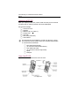
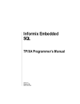
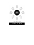
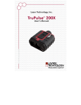
Views of the RD 1000
Figure #1 shows two different views of the RD 1000.
Figure #1
Section 2 - Quick Start
Page 5
Section 2 - Quick Start
Now that you’ve unpacked and have been introduced to the RD 1000, this
section will help you get started with an example of a BAF measurement.
The BAF Mode is covered in more detail in Section 5 (page 18).
1.
Install the batteries (page 6).
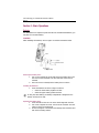
2.
3.
Press-and-hold the Power button
for a approximately 2 seconds.
Select the measurement units.
a. Press the MODE button until the external LCD displays the
SYS Mode Indicator and the message “Prcnt” appears in the
main display.
b. Press the FWD button until the external LCD displays the UNITS
Status Indicator and the Unit Indicators are flashing.
Metric: M and CM Unit Indicators flashing.
Imperial:F and I Unit Indicators flashing.
c. Press the UP or DOWN button to toggle between Metric and
Imperial Measurement Units.
Press the MODE button until the external LCD displays the BAF
Mode Indicator, the EDIT Function Indicator, and the default
(or previous) BAF value.
If you want to use the same BAF value, go to step #6. To enter a
new BAF value, press the EDIT button and then use the arrow
buttons to edit the BAF value.
¶ Valid Values: 1 - 127 (Imperial) or 0.3 - 29.1 (Metric).
a. Press the UP or DOWN button to increase/decrease the value.
b. Press the FWD or BACK button to move to next/previous digit.
c. Press the ENTER button the accept the new BAF value.
Looking through the sighting scope, press-and-hold the TRIGGER
button to activate the illuminated in-scope LED Measurement Bar
Scale and dynamic inclination tracking. The bar scale represents the
subtended horizontal angle away from the unit that corresponds
to the BAF value. The scale adjusts as you aim up or down a slope.
Aim to the tree DBH and release the TRIGGER button. The bar scale
is held and displayed in-scope LED for approximately 30 seconds.
4.
5.
6.
7.
L
•
•
The Magnifier has no practical application in the BAF Mode.
If you are working in Imperial measurement units and want to set
the BAF value to tenth's of a whole number, such as 17.5 BAF:
1. Change the measurement units to Metric (see step #3 above).
2. Return to the BAF Mode (step #5 above) and enter the metric
equivalent of the Imperial BAF value that you want to use.
•
Calculate the metric equivalent by multiplying the
Imperial BAF by 0.22957.
•
For the above example, 17.5 x 0.22957 = 4.0.
3. Continue with steps #6 and #7 above.
Laser Technology, Inc. Criterion RD 1000 User’s Manual
Page 6
Section 3 - Basic Operations
Batteries
Two AA batteries are required to power the RD 1000. Instead of AA batteries, you
may also use one CRV3 battery.
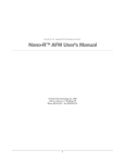
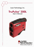
Installation
When installing the batteries, refer to Figure #2 and the instructions below.
Figure #2
Removing the Battery Door:
1. Use a coin to release the screw that secures the battery door. Turn
the screw counter-clockwise. The door will raise as the screw is
released.
2. Once the screw is released, lift the battery door to remove.
Installing the Batteries:
1. Insert the batteries as shown in Figure #2 above.
¶ Insert the lower battery negative end first.
¶ Insert the upper battery positive end first.
L
If using one CRV3 battery, the battery compartment is designed so the
battery will only fit one way.
Replacing the Battery Door:
1. Insert the tab into the slot. The screw should align with the hole.
2. Use a coin to tighten the screw. Turn the screw clockwise. The door
lowers as the screw is tightened.
3. Do not over-tighten. The surface of the battery door should be level
with the surrounding surface.
Section 3 - Basic Operations
Page 7
Low Battery Warning
The RD 1000 monitors the incoming battery voltage.
•
•
When the voltage drops below 2.2V, the External LCD main display
flashes “LobAt” every 5 seconds, alternating with the normally displayed
information.
¶ You should replace the batteries as soon as possible.
When the voltage drops below 2.0V, the “LobAt” message stops flashing
and is displayed steady. At this point system operation is locked.
¶ You must replace the batteries to return to normal system
operation.
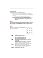
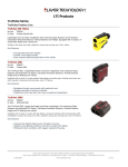
Buttons
The RD 1000 has 11 buttons. Nine of the these buttons are located on the keypad
below the external LCD. The TRIGGER button is located at your index finger on
the front of the unit, and the Scale Adjust button is located at your thumb on the
back of the unit.
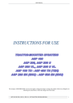
Key Pad
Figure #3 shows the keypad. The table below describes
the function of each button.
Figure #3
EDIT
Activates the edit function (page 9).
↑ UP
System Menu: Toggles value.
Edit function: Increases the digit value.
HUD brightness: Increases the value.
HUD
When the Heads Up Display (HUD) is active, controls the
in-scope LED.
Short Press: Activates the in-scope LED and displays the
brightness value.
Long Press: Toggles the illuminated in-scope LED
Measurement Bar Scale from Solid to Gap or Gap to Solid.
BACK ←
System Menu: Moves to the previous menu item.
Edit function: Moves to the previous digit (right to left).
Measurement: Moves to the previous step.
ENTER ↵
Confirms function. Selects value.
Laser Technology, Inc. Criterion RD 1000 User’s Manual
Page 8
FWD →
System Menu: Moves to next menu item.
Edit function: Moves to the next digit (left to right).
MODE
Moves through the operating modes.
DOWN ↓
System Menu: Toggles value.
Edit function: Decreases the digit value.
HUD brightness: Decreases the value.
Measurement result: Downloads data (page 25).
POWER When unit is OFF:
•
Press and hold for a minimum of 2 seconds turns ON the
unit. For a brief time, all segments are displayed followed
by the firmware revision number, and then the unit is
ready for use.
•
Press and Hold: external LCD shows all display segments
(10 seconds maximum).
When unit is ON:
•
Short press turns the display backlight ON/OFF.
•
Long press (2 seconds minimum) turns OFF the unit.
L
To conserve battery power, if no button presses are detected for a
period of 15 minutes, the RD 1000 automatically turns itself OFF.
Other Buttons
Figure #4 shows the TRIGGER button and the SCALE ADJUST button.
TRIGGER
Short Press: (1) Activates the in-scope LED (stays lit
for 30 seconds if no additional buttons are pressed).
(2) Accepts in-scope target points (such as tree
base, etc.).
Press-and-hold: Activates the tilt sensor, and
measurements are dynamically updated. Upon
release, the inclination reading is locked.
SCALE ADJUST (+)
Increases the width of the illuminated in-scope LED
Measurement Bar Scale.
•
Short Press: Increases the scale by one tick.
•
Press-and-hold: Continuously increases the
scale width change.
Figure #4
SCALE ADJUST (-)
Decreases the width of the illuminated in-scope LED
Measurement Bar Scale.
•
Short Press: Decreases the scale by one tick.
•
Press-and-hold: Continuously decreases the
scale width change.
Section 3 - Basic Operations
Page 9
Display Backlight
When working in low-light conditions, you may find it easier to read the external
LCD if the display backlight is toggled ON. No matter what screen is displayed; the
display backlight may be toggled ON or OFF using a short press the POWER
button.
L
To conserve battery power, you should only use the backlight when
necessary.
Edit Function
The RD 1000’s edit function allows you to manually enter numeric values. The
table below lists the editable values and the valid values for each value.
Valid Values
Editable Value
Imperial
Metric
BAF value
1 - 127
0.3 - 29.1
Diameter
0.1 - 1400.0 inches
0.3 - 3500.0 cm
Horizontal Distance (HD)
1.65 - 999.90 ft
0.51 - 304.76 m
Magnification Constant
2.00 - 2.99
When you come across an editable value:
•
System Mode: The external LCD will display the EDIT Function Indicator.
•
Measurement Mode: The external LCD will display the EDIT Function
Indicator and the corresponding Measurement Prompt Indicator will be
flashing.
To edit a value:
1. Press the EDIT button. The active digit flashes.
2. Enter the desired value using the arrow buttons.
¶ The ↑ button increases the digit value.
¶ The ↓ button decreases the digit value.
¶ The → button activates the next digit (left to right).
¶ The ← button activates the previous digit (right to left).
3. Press the ENTER button to accept the value.
¶ An E05 error code will be displayed if you attempt to enter an
invalid value.
Laser Technology, Inc. Criterion RD 1000 User’s Manual
Page 10
Error Codes
An error code will be displayed if the RD 1000 detects a problem with a
measurement. Depending upon the current function, error codes are displayed in
either the in-scope LED or the external LCD display. The table below lists and
explains the possible error codes.
Code
Explanation
Remedy
E01
Unstable inclination value. The
instrument is too unsteady to
produce an accurate reading.
•
E02
Calculation error. There was an
•
error in performing an internal
calculation caused by improper
measurement geometry. Likely
caused by a incorrectly entered
data value, or an incorrect target
shot from an external laser
device.
Re-enter or re-shoot the
data.
E03
Data communication error. There •
was an error in a received serial
data string from an external
device.
•
Verify that the laser and the
RD 1000 are using the same
units.
Verify the laser mode
(it should be in HD or VD)
and re-shoot.
E04
System memory error. There was •
some type of failure of the
internal system memory. This
represents a memory checksum
failure of factory stored
parameters.
If the error persists, contact
Laser Technology, Inc.
E05
Data entry error. An improper
value was entered during a
manual data edit operation (the
entered data was outside of
acceptable value limits).
Check value and re-enter
data.
E06
Unable to display the input value •
in the in-scope LED or external
•
LCD.
Re-enter data.
Hold the instrument within
tilt limits.
Unable to display the calculated
value.
Press the ENTER button to
continue with the
calculation.
•
•
Steady the instrument
before releasing the
TRIGGER button.
Section 3 - Basic Operations
Page 11
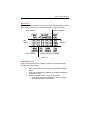
External LCD
Figure #5 shows the external LCD. You will notice that the main display is located
at the center of the screen and that display indicators are grouped by type.
Mode Indicators
Function Indicators
Unit
Indicators
Main
Display
Status Indicators
Measurement Prompt Indicators
Figure #5
Display Indicator Test
Refer to the instructions below and Figure #5 above to verify that all display
indicators are working properly.
1.
2.
3.
Starting with the unit powered OFF, press and hold the POWER
button.
Verify that all indicators are displayed, by comparing the display to
the Figure #5 above.
Release the POWER button to start normal operation.
¶ If you do not release the POWER button, the unit will power
down after approximately 10 seconds.
Laser Technology, Inc. Criterion RD 1000 User’s Manual
Page 12
Firmware Revision Number
The firmware revision number provides manufacturing information about your
RD 1000. Each time the RD 1000 is powered ON, the external LCD displays the
firmware revision number, “r 1.xx” (where ‘xx’ is a value from 00 to 99).
In-scope LED
When the Heads Up Display (HUD) is active, the HUD button controls the
in-scope LED.
•
Short Press: Activates the in-scope LED and displays the brightness
value for approximately 3 seconds.
•
Long Press: Toggles the illuminated in-scope LED between Measurement
Bar Scale between Solid Mode and Gap Mode.
Brightness
To accommodate working in different lighting conditions, you may adjust the
brightness level of the in-scope LED. The brightness value is stored in memory.
The last value used is maintained when the unit is powered ON. Refer to the
instructions below to display and change the brightness value.
1.
2.
3.
Press the HUD button to activate the in-scope LED. Both the
in-scope LED and external LCD display the brightness value
as “br X”.
¶ Where ‘X’ is a value from 1 to 7.
Press the UP button to increase the value.
Press the DOWN button to decrease the value.
¶ The unit will return to normal system operation approximately
3 seconds after the last button press.
Section 3 - Basic Operations
Page 13
Measurement Bar Scale
Figure #6 shows the two Measurement Bar Scale modes: Solid and Gap.
The Measurement Bar Scale mode is stored in memory, the last mode used is
maintained when the unit is powered on.
Gap Bar Scale
Solid Bar Scale
Figure #6
Refer to the instructions below to change the Measurement Bar Scale mode.
1.
L
Long press the HUD button to toggle to the other scale. A message
corresponding to the new scale “GAP” or “SLd” is displayed in both
the in-scope LED and external LCD display .
¶ The unit will return to normal system operation approximately
3 seconds after the last button press.
In most situations, you will find that the Solid Bar Scale works best in
the BAF Mode, and that the Gap Bar Scale works best in the Diameter
and Height/Diameter Modes.
Neck Strap
Figure #7
Laser Technology, Inc. Criterion RD 1000 User’s Manual
Page 14
Section 4 - System Functions
Figure #8 shows an overview of the System functions. To select the System
Mode, press the MODE button until the external LCD displays the SYS Mode
Indicator and the message “Prcnt” appears in the main display. The SYS Mode
indicator is displayed when the System Mode is active. Press the FWD button or
BACK button to move between the functions.
Figure #8
Displaying Percent Slope
The RD 1000’s tilt sensor allows you to view inclination values. Values are
displayed in the in-scope LED and appear as whole units of percent slope.
Percent Slope = (Tan
1.
2.
3.
θ) x 100
Press the MODE button until the external LCD displays the SYS
Mode Indicator and the message “Prcnt” appears in the main
display.
Looking through the sighting scope, press-and-hold the TRIGGER
button to activate the tilt sensor. The horizontal aiming marks and
the percent slope appear in the in-scope LED.
a. The value updates as long as you hold the TRIGGER
button.
b. When you release the TRIGGER button, the percent slope
is locked and is displayed in the in-scope LED for a
maximum of 30 seconds (if no other buttons are pressed).
c. To download a serial data string through the serial port to
an external data collector, press the DOWN button.
¶ The serial data string contains the raw inclination, it
does not contain the percent slope (page 27).
Press-and-hold the TRIGGER button to repeat this process.
¶ Press the FWD button to move to the next System function.
¶ Press the BACK button to move to the previous System
function.
¶ Press the MODE button to select a measurement mode.
Section 4 - System Functions
Page 15
Using the Magnifier
When you are measuring diameters and your work requires maximum
measurement resolution, you will want to attach the Magnifier to the RD 1000 and
turn ON the magnification constant. The Magnifier modifies the subtended angle
represented in the in-scope LED Measurement Bar Scale, covering an overall
smaller range of angles. Thereby increasing the individual bar ‘tick’ resolution. You
should note that the Magnifier has no practical use in the BAF Mode.
Each Magnifier is labelled with its own unique magnification constant. The
magnification constant is stored in RD 1000’s memory. The constant must be
toggled ON when the magnifier is attached to the RD 1000, and toggled OFF
when the magnifier is not attached to the RD 1000. The external LCD displays the
MAG Status Indicator when the Magnification Constant is toggled ON. As long as
you are using the Magnifier that shipped with your RD 1000, you should not ever
have to change the value of the constant.
Attaching the Magnifier
1.
2.
3.
Grasp the magnifier by the front,
outside edges opposite the
threads.
Position the magnifier front of the
RD 1000 as shown in Figure #9 so
the threads are aligned.
Turn the magnifier clockwise to
secure to the RD 1000. Do not
force the first few turns and
tighten until snug.
Figure #9
Removing the Magnifier
1.
2.
Grasp the magnifier by the front, outside edges.
Turn the magnifier counter-clockwise.
Turning the Magnification Constant ON or OFF
1.
2.
3.
Press the MODE button until the external LCD displays the SYS
Mode Indicator.
Press the FWD or BACK button until the MAG Status Indicator is
displayed and “OFF” or “On” appears in the main display.
Press the UP or DOWN button to toggle the selection.
¶ Press the FWD button to move to the next System Option.
¶ Press the BACK button to move to the previous System Option.
¶ Press the MODE button to select a measurement mode.
Laser Technology, Inc. Criterion RD 1000 User’s Manual
Page 16
Displaying the Magnification Constant
1.
2.
3.
Press the MODE button until the external LCD displays the SYS
Mode Indicator.
Press the FWD or BACK button until the MAG Status Indicator is
displayed and “OFF” or “On” appears in the main display.
¶ If “OFF” is displayed, press the UP or DOWN button to toggle
“ON”.
Press and hold the EDIT button for approximately 3 seconds. The
current Magnification constant appears in the main display. This
value should match the number that appears on the magnifier.
¶ If you want to use the same Magnification Constant, press the
MODE button to select a measurement mode.
¶ See below to edit the value of the Magnification Constant.
¶ Press the FWD button to move to the next System Option.
¶ Press the BACK button to move to the previous System Option.
Editing the Value
1.
2.
Display the Magnification Constant (see above).
Press the EDIT button and use the arrow buttons to edit the value.
¶ Valid Values: 2.00 to 2.99.
a. Press the UP or DOWN button to increase/decrease the
value.
b. Press the FWD or BACK button to move to next/previous
digit.
c. Press the ENTER button to accept the new Magnification
constant.
¶ Press the MODE button to select a measurement mode.
¶ Press the FWD button to move to the next System Option.
¶ Press the BACK button to move to the previous System Option.
Selecting Measurement Units
The RD 1000 allows you to choose between Metric and Imperial measurement
units. Refer to the instructions below to toggle the selection.
1.
2.
3.
Press the MODE button until the external LCD displays the SYS
Mode Indicator.
Press the FWD or BACK button until the Units Status Indicator and
distance measurement Unit Indicators (flashing) are displayed.
Press the UP or DOWN button to toggle between Imperial and
Metric Units.
Metric: M and CM flashing. Imperial: F and I flashing.
¶ Press the FWD button to move to the next System option.
¶ Press the BACK button to move to the previous System option.
¶ Press the MODE button to select a measurement mode.
Section 4 - System Functions
Page 17
L
When using an LTI laser range finder with your RD 1000, you should
verify that you have selected the same measurement units in both
instruments. If the RD 1000 and the laser are not using the same
measurement units, the RD 1000 will convert the measurement data
received from the laser. For example, if the RD 1000 is using Imperial
units, and the laser is using Metric units, the RD 1000 will convert the
measurement data received from the laser to Imperial units.
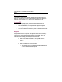
Aligning the Tilt Sensor
In the rare event that the unit suffers a severe drop shock, refer to the
instructions below to align the tilt sensor.
1.
2.
3.
Press the MODE button until the external LCD displays the SYS
Mode Indicator.
Press the FWD or BACK button until the CAL Function Indicator is
displayed and the message “rEF 1” appears in the main display.
Position the RD 1000 on a flat, relatively level surface as shown in
Figure #10(A).
¶ Do not lift or raise the unit until the message “dOnE” is
displayed in step #6 below.
Figure #10
4.
5.
6.
Press the ENTER button to store the inclination measurement. The
message “rEF 2” appears in the main display.
Slowly rotate the RD 1000 180 degrees as shown in Figure #10(B).
Press the ENTER button to store the inclination measurement and
make the zero offset correction. The message “dOnE” appears in the
main display before the message “ref 1” is displayed.
¶ Press the FWD button to move to the next System option.
¶ Press the BACK button to move to the previous System option.
¶ Press the MODE button to select a measurement mode.
Laser Technology, Inc. Criterion RD 1000 User’s Manual
Page 18
Section 5 - BAF-scope Functions
•
BAF Mode: Specify a Basal Area Factor value and visually estimate if
trees fall “In” or “Out” of a given plot. The Magnifier has no application
in this mode.
IN/OUT Mode: Use the internally stored plot radius factors to
determine the status of “borderline” trees.
•
BAF Mode
Refer to the instructions below to complete a BAF measurement.
1.
2.
3.
4.
L
•
•
•
•
Press the MODE button until the external LCD displays the BAF
Mode Indicator, the previously entered (or default) BAF value, and
the EDIT Function Indicator. This is prompting you to enter a
different BAF value.
¶ If you want to use the same BAF value, go to step #3.
To enter a different BAF value, press the EDIT button and then use
the arrow buttons to edit the value.
¶ Valid Values: 1 - 127 (Imperial) or 0.3 - 29.1 (Metric).
a. Press the UP or DOWN button to increase/decrease the
value.
b. Press the FWD or BACK button to move to next/previous
digit.
Press the ENTER button to accept the BAF value. Looking through
the sighting scope, press-and-hold the TRIGGER button to activate
the illuminated in-scope LED Measurement Bar Scale and dynamic
inclination tracking. The bar scale represents the subtended
horizontal angle away from the unit that corresponds to the
specified BAF value. The scale automatically adjusts as you aim up
or down a slope. The BAF value is also displayed in the in-scope
LED numeric field.
Aim to the tree DBH and release the TRIGGER button.
¶ The tilt sensor is only activated when the TRIGGER button is
pressed and held. As long as you hold the TRIGGER button, the
tilt sensor continues to operate and update the displayed data.
¶ When you release TRIGGER button, the bar scale is held and
displayed in the in-scope LED for approximately 30 seconds.
Repeat the above steps to take another BAF measurement.
In most situations, you will find that the Solid Bar Scale works
best in the BAF Mode. However, you can toggle the illuminated
in-scope LED measurement scale from Solid to Gap (page 13).
The Magnifier has no practical use in this mode.
If you are working in Imperial measurement units and want to set
the BAF value to tenth’s of a whole number, refer to the example
on page 5.
Section 5 - BAF-scope Functions
Page 19
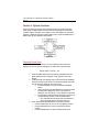
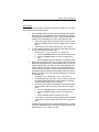
In/Out Mode
Refer to the instructions below to determine the status of “borderline” trees using
the internally stored plot radius factors.
1.
2.
3.
Press the MODE button until the external LCD displays the IN/OUT
Mode Indicator, the DIAM Measurement Prompt Indicator (blinking),
the appropriate Units Indicator ("CM" or "I") and the EDIT Function
Indicator. This is prompting you to enter a new diameter value.
¶ If you have logged a previous diameter value measured in the
Diameter operating mode, this value is displayed in the external
LCD.
¶ If you want to use the same diameter value, go to step #3.
To enter a different diameter value, press the EDIT button and then
use the arrow buttons to edit the value.
¶ Valid Values: 0.1 - 1400.0 inches or 0.3 - 3500.0 cm.
a. Press the UP/DOWN button to increase/decrease the value.
b. Press the FWD/BACK button to move to next/previous
digit.
c. Press the ENTER button to accept the new diameter value.
Based upon the diameter value that you entered, the external LCD
displays the Limiting Distance. Press the ENTER button to accept the
Limiting Distance value. (An E06 error code will be displayed if the
Limiting Distance is to large to display. Press the ENTER button to
continue with the calculation). The EDIT Function Indicator should
be displayed and the HD Measurement Prompt Indicator should be
blinking; prompting you to enter the horizontal distance to the face
of the target tree.
¶ Valid Values: 1.65 - 999.90 feet or 0.51 - 304.76 meters.
¶ To automatically fill-in: Aim and fire your LTI laser to download
the measured HD value into the numeric display. The display
will automatically advance to the next step.
¶ To manually enter: Measure the distance using a tape measure,
press the EDIT button, and use the arrow buttons to edit the
value.
a. Press the UP/DOWN button to increase/decrease the value.
b. Press the FWD/BACK button to move to next/previous
digit.
c. Press the ENTER button to accept the HD value.
¶ If you want to re-enter the horizontal distance (either manually
or with a laser), press the BACK button and enter a new HD
value.
Directly following manual entry of the horizontal distance, or receipt
of the laser serial data string, the external LCD should indicate if the
measured tree is "In" or "Out" of the plot.
Laser Technology, Inc. Criterion RD 1000 User’s Manual
Page 20
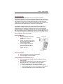
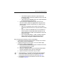
Section 6 - Dendrometer Functions
•
•
Diameter Mode: Acquire a direct read-out of the height and diameter
of a tree at any point (or multiple points) along the stem.
HT/Diameter Mode: Determine the height at which a specific target
diameter is reached.
Diameter Mode
Refer to the instructions below to acquire a direct read-out of the height and
diameter of a tree at any point (or multiple points) along the stem ⎯ from any
convenient distance away. For increased accuracy at further distances from the
tree, attach the Magnifier and turn on the Magnification Constant (page 15).
1.
2.
4.
5.
6.
Press the MODE button until the external LCD displays the
DIAMETER Mode Indicator, the HD Measurement Prompt (flashing),
the appropriate Units Indicator ("F" or "M"), and the EDIT Function
Indicator. This is prompting you enter the horizontal distance to the
target tree.
Enter the horizontal distance.
¶ Valid Values: 1.65 - 999.90 feet or 0.51 - 304.76 meters.
¶ To automatically fill-in: Aim and fire your LTI laser range finder
to download the measured HD value into the numeric display.
The display will automatically advance to the next step.
¶ To manually enter: Measure the distance using a tape measure,
press the EDIT button, and use the arrow buttons to edit the
value.
a. Press the UP or DOWN button to increase/decrease the
value.
b. Press the FWD or BACK button to move to next/previous
digit.
c. Press the ENTER button to accept the HD value.
¶ If you want to re-enter the horizontal distance (either manually
or with a laser), press the BACK button and enter a new HD
value.
The external LCD displays the DIAMETER Mode Indicator, the
ANGLE Measurement Prompt Indicator (flashing), the DEG Units
indicator, and the message “bASE” is prompting you to take the
base angle measurement to the tree. This message is also displayed
in the numeric area of the in-scope LED.
Looking through the sighting scope, press-and-hold the TRIGGER
button to activate the illuminated in-scope LED Measurement Bar
Scale.
Aim to the base of the target tree, and release the TRIGGER button
to lock the inclination measurement.
Section 6 - Dendrometer Functions
Page 21
¶ The inclination appears in both the in-scope LED and the
7.
external LCD, and is continuously updated as long as you hold
the TRIGGER button.
¶ Upon release of the TRIGGER button, the in-scope LED flashes
the locked inclination measurement.
Press-and-hold the TRIGGER button again and scan up the
tree from the base. Release the Trigger button at any given tree
height to lock the inclination measurement, for example 4.5 feet
(or 1.3 meters).
¶ While you are tracking up the tree stem, the tree height is
dynamically updated in both the in-scope LED and the external
LCD.
¶ When you release the TRIGGER button, the tree diameter is
shown in both the in-scope LED and the external LCD. This
value is based upon the width of the illuminated in-scope LED
Measurement Scale.
¶ Now use the SCALE ADJUST (+) AND (-) buttons to align the
edges of the bar scale with the edges of the target tree,
simultaneously changing the displayed diameter value.
Once the measured tree diameter is shown in the displays:
•
To download a serial data string through the serial port to an external
data collector, press the DOWN button.
•
To display the height on the tree again, or move to another height
position for a diameter measurement:
1. Press-and-hold the TRIGGER button again to activate the tilt sensor
and dynamically display tree heights.
2. Scan to the desired tree height.
3. Release the TRIGGER button to lock the inclination measurement
and show the diameter at the given tree height point.
4. Repeat the diameter measurement step (#7) above.
L
•
•
In most situations, you will find that the Gap Bar Scale works best
in the Diameter Mode. However, you can toggle the illuminated
in-scope LED measurement scale from Solid to Gap (page 13).
For increased accuracy at further distances from the tree, attach
the Magnifier (page 15).
Laser Technology, Inc. Criterion RD 1000 User’s Manual
Page 22
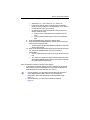
Height/Diameter Mode
Refer to the instructions below to determine the height along the stem at which a
specific diameter is reached. For increased accuracy at further distances from the
tree, attach the Magnifier and turn on the Magnification Constant (page 15).
1.
2.
4.
5.
6.
7.
Press the MODE button until external LCD displays the
HT/DIAMETER Mode Indicator, the HD Measurement Prompt
Indicator (flashing), the appropriate Units Indicator ("F" or "M") and
the EDIT Function Indicator. This is prompting you enter the
horizontal distance to the target tree.
Enter the horizontal distance.
¶ Valid Values: 1.65 - 999.90 feet or 0.51 - 304.76 meters.
¶ To automatically fill-in: Aim and fire your LTI laser range finder
to download the measured HD value into the numeric display.
The display will automatically advance to the next step.
¶ To manually enter: Measure the distance using a tape measure,
press the EDIT button, and use the arrow buttons to edit the
value.
a. Press the UP or DOWN button to increase/decrease the
value.
b. Press the FWD or BACK button to move to next/previous
digit.
c. Press the ENTER button to accept the HD value.
¶ If you want to re-enter the horizontal distance (either manually
or with a laser), press the BACK button and enter a new HD
value.
The external LCD displays the HT/DIAMETER Mode Indicator, the
ANGLE Measurement Prompt Indicator (flashing), the DEG Units
Indicator, and the message “bASE” is prompting you to take the
base angle measurement to the tree. This message is also displayed
in the numeric area of the in-scope LED.
Looking through the sighting scope, press-and-hold the TRIGGER
button to activate the illuminated in-scope LED Measurement Bar
Scale.
Aim to the base of the target tree. When the desired base angle
target point is identified, release the TRIGGER button to lock the
inclination measurement.
¶ The inclination appears in both the in-scope LED and the
external LCD, and is continuously updated as long as you hold
the TRIGGER button.
¶ Upon release of the TRIGGER button, the in-scope LED flashes
the locked inclination reading.
The external LCD displays the DIAM Measurement Prompt Indicator
(flashing), the appropriate Units Indicator (“I” or CM”), and the
EDIT Function Indicator prompting you to enter a diameter value.
Enter or edit the diameter value.
Section 6 - Dendrometer Functions
Page 23
¶ Valid Values: 0.1 - 1400.0 inches or 0.3 - 3500.0 cm.
¶ If a previous diameter value was measured in the Diameter
Mode, this value will appear in the main display. If you want to
use this diameter value, go to step #8.
¶ To manually enter, press the EDIT button and use the arrow
buttons to edit the value.
a. Press the UP or DOWN button to increase/decrease the
value.
b. Press the FWD or BACK button to move to next/previous
digit.
8. Press the ENTER button to accept the diameter value.
9. Press-and-hold the TRIGGER button to activate the tilt sensor and
track up the tree from the base.
¶ The tree height is dynamically updated in both the in-scope LED
and the external LCD.
10. When the horizontal aiming marks align with the edges of the target
tree, release the TRIGGER button to lock the inclination
measurement.
¶ The tree height is shown in both the in-scope LED and external
LCD.
¶ To re-check or re-position the height measurement point, press
and hold the TRIGGER again to activate the tilt sensor and view
the updated height measurement.
Once the desired tree height is showing in the displays:
•
To download a serial data string through the serial port to an external
data collector, press the DOWN button. The external LCD displays the
DIAM Measurement Prompt Indicator (see step #7).
L
•
•
In most situations, you will find that the Gap Bar Scale works best
in the Height/Diameter Mode. However, you can toggle the
illuminated in-scope LED measurement scale from Solid to Gap
(page 13).
In some situations, you may want to attach the Magnifier
(page 15).
Laser Technology, Inc. Criterion RD 1000 User’s Manual
Page 24
Section 7 - Serial Data Interface
The RD 1000’s two serial ports are used to communicate with external devices.
The Laser Port is a dedicated interface to an LTI laser, and the Data Port is a
dedicated interface to an external data collector. The accessories needed for
downloading measurement data are available from LTI or an Authorized LTI
Distributor.
The serial data interface uses RS232 voltage levels and transfers information in
an ASCII, hexadecimal format. Figure #11 shows the pin-out assignments for the
RD 1000’s two serial port connectors.
Figure #11
Data Format
The RD 1000 uses the Criterion 400 data format.
Format Parameters
•
•
•
•
•
Baud rate
Start bit
Data bit
Stop bit
Parity
4800 BPS
1
8
1
None
Section 7 - Serial Data Interface
Page 25
Impulse Settings
When an Impulse laser is connected to the Laser Port, the Data Port echoes out
any serial data strings that come in from the laser.
1.
2.
3.
L
Set Auto Download to ON.
Set the download format to CR400. The RD 1000 cannot
communicate with the Impulse in the Impulse native data format.
Select the measurement mode: HD or VD.
If your Impulse is Revision 1.43 or newer, determine if you want the
Impulse to automatically output valid measurements only, or to output
data strings that may contain null data from error conditions, by using
the Err system setting. You need only be concerned with the Err setting
if you are using the Impulse in automatic download mode. If you need
more information about Impulse revision number or the Err system
setting, refer to the user’s manual that shipped with your Impulse.
TruPulse Settings
When a TruPulse laser is connected to the Laser Port, the Data Port echoes out
any serial data strings that come in from the laser.
1. Select the measurement mode: HD or VD.
L
The CR400 serial data string is automatically downloaded once a shot is
taken.
Input Data String
The RD 1000 only responds to an incoming CR400 data string that contains a
horizontal distance value (horizontal vector data string). For more information
about this data string, refer to the user’s manual that shipped with your LTI laser.
Output Data String
The RD 1000 generates and outputs two data strings, Horizontal Vector
(HV message type) and Tree Diameter (DA message type). Measurement results
may be downloaded in the following situations:
•
•
•
Diameter result
Height/Diameter result
Locked raw inclination value measured in Percent Slope
Laser Technology, Inc. Criterion RD 1000 User’s Manual
Page 26
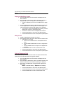
Tree Diameter Download Message
Diameter results and Height/Diameter results are downloaded as a Tree diameter
message and have the following format:
$PLTIT,DA,height,ht units,diameter,d units*checksum <CR><LF>
$PLTIT
Criterion 400 message identifier.
DA
Tree diameter message type.
height
Height from base.
ht units
Height units.
F = feet
M = meters
diameter
Diameter at height.
d units
Diameter units.
I = inches
C = centimeters
*checksum
Asterisk followed by a hexadecimal
checksum. Calculated by XORing all the
characters between the ‘$’ and the ‘*’.
<CR><LF>
Carriage return / line feed combination.
Imperial:
$PLTIT,DA,12.49,F,15.04,I*7D
Metric:
$PLTIT,DA,22.02,M,10.00,C*71
Examples
Section 7 - Serial Data Interface
Page 27
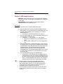
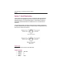
Raw Inclination Download Message
Although the RD 1000 displays raw inclination measurements as Percent Slope
(page 14), locked values are downloaded as angles and only have the following
format:
$PLTIT,HV,horiz dist,units,az,units,inc,units,sd,units*checksum<CR><LF>
$PLTIT
Criterion 400 message identifier.
HV
Horizontal Vector message type.
horiz dist
Horizontal distance.
Always a null value.
units
Horizontal distance units.
Always a null value.
az
Azimuth.
Always a null value.
units
Azimuth units.
Always a null value.
inc
Inclination.
units
Inclination units.
D = degrees
sd
Slope distance.
Always a null value.
units
Slope distance units.
Always a null value.
*checksum
Asterisk followed by a hexadecimal
checksum. Calculated by XORing all the
characters between the ‘$’ and the ‘*’.
<CR><LF>
Carriage return / line feed combination.
Example
$PLTIT,HV,,,,,20.31,D,,*0D
Percent Slope = (Tan 20.31°) x 100 = 37%
Laser Technology, Inc. Criterion RD 1000 User’s Manual
Page 28
Section 8 - Care & Maintenance
The batteries are the only user-replaceable parts in the RD 1000. Do not remove
any screws, other than the screw for the battery door. To do so will effect or void
the LTI Limited Warranty.
Temperature Range
The instrument components are rated for a temperature range of
-22º F to +140º F (-30º C to +60º C). Do not expose the RD 1000
to temperatures outside this range.
Protecting from Moisture and Dust
The RD 1000 is sealed to provide protection from normally expected field
conditions. It is protected from dust and rain, but will not withstand submersion.
If water leakage is suspected:
1. Power OFF the RD 1000.
2. Remove the batteries.
3. Air dry the RD 1000 at room temperature with the battery
compartment open.
Protecting from Shock
The RD 1000 is a precision instrument and should be handled with care. It will
withstand a reasonable drop shock. If the unit suffers from a severe drop shock,
you may need to align the tilt sensor (page 17).
Transporting
When transporting the RD 1000 in a vehicle, the unit should be secured in the
provided carrying case. The provided neck strap can be used when carrying the
RD 1000 in the field.
Cleaning
Clean the RD 1000 after each use, before returning it to its carrying case. Check
all of the following items:
Excess moisture. Towel off excess moisture, and air dry the instrument at room
temperature with the batteries removed and the battery compartment open.
Exterior dirt. Wipe exterior surfaces clean to prevent grit buildup in the carrying
case. Isopropanol may be used to remove dirt and fingerprints from the exterior.
Sighting Scope Lenses. Use the provided lens cloth to wipe the sighting scope’s
lenses and the external LCD. Failure to keep the lenses clean may damage them.
A damaged scope lens can make it difficult to see a target.
Section 8 - Care & Maintenance
Page 29
Testing the Display Segments
It is a good idea to periodically check the external LCD to make certain that all
display segments are working properly. For more information, see page 11.
Storing
If you won't be using the RD 1000 again soon, remove the batteries before
storing the instrument.
Laser Technology, Inc. Criterion RD 1000 User’s Manual
Page 30
Section 9 - Specifications
Specifications are subject to change without notice. Please refer to LTI’s web site for current specifications.
Dimensions:
2.75" x 2.00" x 6.5"
(7 cm x 5 cm x16.5 cm)
Weight:
1.1 pounds (500 grams)
Data Communications:
RS232, NMEA 0183,
Proprietary Record Data Format
Power:
3.0 volts DC nominal.
Battery Type:
Operation Duration:
AA (2) or CRV3 (1)
AA: Approximately 20 hours.
CRV3: Approximately 40 hours.
Environmental:
Water and dust resistant.
NEMA 3, IP54
Operating Temperature:
-22º F to +140º F
(-30º C to +60º C)
Optics:
Normal:
Magnified:
1X
2.00 - 2.99 (value listed on the Magnifier)
Displays:
External LCD and In-scope LED
Units:
Imperial and Metric
Monopod/Tripod Mount:
¼" - 20
Measurement Range:
BAF:
Diameter:
Inclination:
Accuracy:
Diameter:
Inclination:
1 to 127 Ft²/Acre (0.2 to 29.1 M²/Hectar)
2" to 100" (5 cm to 254 cm) under typical
field conditions.
+/- 90º (360º full circle)
±¼" (6 mm) up to 80 feet (24 m) away
under typical field conditions. Maximum
diameter achievable is 1400" based on the
maximum allowable distance entry, but
accuracy will be limited to 1% of
measurement.
±0.1º typical
Section 10 - Troubleshooting Tips
Page 31
Section 10 - Troubleshooting Tips
Problem
Unit fails to
power up.
Remedy
Remove the battery door and ensure that the battery
connection is good.
1. Verify battery orientation (page 6).
2.
Long press the Power button
unit.
to turn ON the
¶ If you are using two AA batteries and the
problem persists, install a CRV3 battery and
repeat step #2.
¶ If you are using a CRV3 battery and the
problem persists, contact LTI.
Diameter
If you are not using the Magnifier, ensure that the LCD
reading is 1/2 of does not show "MAG". To turn the Magnification Constant
what it should
OFF, see page 15.
be.
Diameter
If you are using the magnifier, ensure that the LCD shows
reading is 2x
"MAG". To turn the Magnification Constant ON, see
larger than what page 15.
it should be.
The Magnifier
was attached
during a BAF
measurement.
If you mistakenly leave the magnifier attached while in
the BASAL AREA mode, more than twice the number of
trees will appear to be in your plot than should be for the
specified basal area factor.
1. Remove the Magnifier (page 15).
2. Turn the Magnification Constant OFF (page 15).
3. Repeat the BAF measurement.
If the above troubleshooting tips do not resolve your problem,
please contact LTI for assistance. Refer to the inside front cover for
LTI contact information.
Laser Technology, Inc. Criterion RD 1000 User’s Manual
Page 32
Index
D
A
accessory items 4
aligning
tilt sensor 17
ANGLE measurement prompt
B
BACK button 7
backlight 9
BAF mode indicator 18
BAF value
valid values 9
BAF-scope functions 18
bASE message 20, 22
basic package
contents 4
batteries 6
battery door 6
baud rate 24
borderline trees 19
br X message 12
brightness value 12
buttons 7
C
CAL function indicator
cleaning 28
Criterion 400
data format 24
17
20, 22
data bit 24
data format 24
data port 24
dendrometer functions 20
DIAM measurement prompt 19,
diameter
valid values 9
Diameter mode 20
DIAMETER mode indicator 20
diameter reading
incorrect 31
display backlight 9
display indicator test 11
DOWN button 8
drop shock 28
E
EDIT button 7
edit function 9
ENTER button 7
error codes 10
excess moisture 28
exterior dirt 28
external LCD 11
F
fail to power up 31
firmware revision number
function indicators 11
FWD button 8
12
22
Index
Page 33
M
G
gap bar scale
gAP message
13
13
H
HD measurement prompt 19, 20,
HD. See horizontal distance
Height/Diameter mode 22
horizontal distance 3
valid values 9
HT/DIAMETER mode indicator 22
HUD button 7
I
Impulse settings 25
In/Out mode 19
IN/OUT mode indicator
input data string 25
in-scope LED 12
installing
batteries 6
K
keypad
7
L
laser port 24
lenses 28
limiting distance 19
LobAt message 7
22
MAG status indicator 15
Magnification Constant
display/edit value 16
turn on/off 15
valid values 9
magnifier 15
main display 11
measurement bar scale 13
measurement prompt indicators
measurement units 16
MODE button 8
mode indicators 11
moisture protection 28
N
19
neck strap
13
output data string
O
25
P
parity 24
percent slope 14
POWER button 8
power conservation
Prcnt message 14
8, 9
Q
quick start
5
11
Laser Technology, Inc. Criterion RD 1000 User’s Manual
Page 34
R
raw inclination download message
rEF 1 message 17
rEF 2 message 17
S
SCALE ADJUST button 8
serial data interface 24
SLD message 13
solid bar scale 13
specifications 30
start bit 24
status indicators 11
stop bit 24
storing 29
SYS mode indicator 14
system functions 14
T
27
temperature range 28
tilt sensor
aligning 17
transporting 28
tree diameter download message
TRIGGER button 8
troubleshooting 31
TruPulse settings 25
U
unit indicators
units 16
UP button 7
11
V
views of the RD 1000
W
warranty 28
water leakage
28
4
26