1
GEM-K1VPS Keypad
R
333 Bayview Avenue
Amityville, New York 11701
For Sales and Repairs, (800) 645-9445
For Technical Service, (800) 645-9440
INSTALLATION INSTRUCTIONS
Publicly traded on NASDAQ
Symbol: NSSC
GENERAL DESCRIPTION
The NAPCO GEM-K1VPS keypad are "smart" userfriendly, voice-interactive menu-driven keypads with
UL-approved PIR and siren designed for use with the
NAPCO GEM-P1664 control panel.
The GEM-K1VPS keypad is armed by entering a
valid user code and pressing STAY or AWAY; they
both provide an alphanumeric screen to display the
status of your system (in addition, a programmable
option exists for "Hold Down STAY/AWAY Arming").
The integral speaker in the keypad provide step-bystep instructions to guide the user through all operations. The GEM-K1VPS combines all of the above
features with the addition of an integral wide-angle
PIR motion sensor and integral siren to provide fast
and easy installation. Note: In UL installations, a
small acoustic cloth that covers the siren module
must be removed to comply with UL Audibility requirements. (See page 13 for more information).
INTEGRAL PIR SENSOR
The GEM-K1VPS keypad's microprocessorcontrolled PIR motion sensor is considered a standard PIR detector that, when enabled, activates the
first zone of the integral EZM only in the armed state
(for ease of arming, the PIR is not active when the system is disarmed.
Note that the PIR can be tested when
disarmed using the PIR test menu option in the Keypad Menu Mode). If the
system is armed in the Away mode,
the keypad PIR will generate an alarm
if an intruder is detected (in this case,
the system may only be disarmed and
silenced by the entering a valid user
code at the keypad). Note: The keypad PIR occupies the first zone of the integral EZM
when the PIR is enabled; therefore be sure to enable
the first zone of the integral keypad EZM when using
the keypad PIR. The PIR zone should also be programmed as a STAY zone and E/E Follower zone.
In addition, the keypad PIR is used to make decisions for initiating certain voice prompts, and is also
used to control the keypad back-lighting to reduce
system standby current, thus increasing energy conservation (see page 3).
INTEGRAL 4 ZONE EZM
Both keypads contain an integral 4 zone EZM, allowing the zone capacity of the control panel to be expanded. With the GEM-P1664 control panel, installing 4 keypads adds a total of 16 zones to the system.
© NAPCO 2009
WI1808 3/09
Additional GEM-EZM's and/or GEM-EZM4-8's can
also be added, thus maximizing the capacity of the
GEM-P1664 control panel to a grand total of 64
zones within the system. Note: If using the keypad
PIR, be sure to enable the first zone of the integral
keypad EZM.
INSTALLATION
Each of up to 7 keypads can be installed on the
GEM-P1664 control panel 4-wire bus. See Control
Panel Installation Instructions for maximum control
panel loading. The GEM-K1VPS includes an integral
siren that produces 85dB (at 10 feet) as required for
UL Residential Burglar and Fire. At least one keypad
shall be powered by the control panel.
POWER
The GEM-K1VPS is powered by the keypad bus of
the control panel or an appropriately rated UL Listed
Security/Signaling power limited power supply rated
12VDC. The voltage rating for all models is 11.7 13.9VDC, 70mA standby and 210mA in alarm. For
fire installations, the keypad shall be powered by the
control panel only, or use an external Listed audible
signaling device on the control panel Bell circuit. The
standby current may be reduced by cutting jumper "W1" which disables the
keypad backlighting entirely. Deduct
these values from the system standby
current, as described in the control
panel wiring diagram.
INSTALLATION PROCEDURES
After wiring and mounting the GEMP1664 control panel, turn to page 4 and
begin the procedures necessary for installing a GEM-K1VPS keypad.
After completing the procedures, return to this section to
configure the other options necessary for each keypad installed in the system, as detailed in the next
section Configuring the Keypad, below.
A. CONFIGURING THE KEYPAD
If not in already, enter Keypad Configuration
Mode by placing the GEM-P1664 panel jumper in
Configuration Mode, the keypad LCD text will display "OUT OF SYSTEM" within 60 seconds (you can
also press keypad buttons 1, 2 and 3 simultaneously to display "OUT OF SYSTEM"). Press "11123"
and press MENU to enter the Keypad Configuration Mode.
Once the Keypad Configuration Mode is accessed,
*Not evaluated by UL.
1
all messages will display in the order shown below
(press MENU to scroll through the list or press RESET to exit). For more complete information, see
the GEM-P1664 panel programming instructions,
WI1810. :
• KEYPAD BEEP
• ENTRY SOUNDER
• KEYPAD ADDRESS
• EZM ADDRESS
• ZONE RESPONSE
• BACKLIGHT BRIGHTNESS
• PIR
• BACKLIGHT FOLLOW PIR
• SIREN
• TAMPER DETECT
B. EASY MENU DRIVEN PROGRAM MODE
Program the panel using the Easy Menu Driven
Program Mode (or use PCD-Windows Quickloader
Download software). See page 9. For complete
details, see programming instructions WI1810.
C. TEST EACH KEYPAD PIR
Note: If the PIR is not enabled, this selection is
not available in Keypad Menu Mode (see page 12).
Enter a valid user program code (a code programmed by the Dealer to allow user programming
and higher functions) and enter the Keypad Menu
Mode by pressing MENU.
Press NO until
"ACTIVATE PIR TEST" appears in the LCD window
and perform a walk test of each keypad PIR as follows:
Allow at least 3 minutes for the unit to settle. Test
the PIR by walking in front of the keypad across
the protected area. When the PIR senses activity,
the display indicates the violated zone and the keypad sounder turns on. Walk out to the maximum
range and walk across the field of coverage.
Check for environmental disturbances with all disruptive devices (heaters, air conditioners, etc.)
turned on and with no human activity within the
coverage area.
D. TEST KEYPAD SIREN
In the Keypad Menu Mode, press MENU until Test
Siren appears, then press YES. Siren will sound
at full volume for 2 seconds.
E. TEST THE SYSTEM
After completing all tasks, perform a test of the entire system, including all keypad(s) and zones.
PANEL PROGRAMMING OVERVIEW
For proper system operation, the GEM-P1664 control
panel is pre-programmed at the factory with features
selected for proper operation. The panel can be reprogrammed using either Easy Menu Driven Program Mode (see page 9) or by using PCD-Windows
Quickloader Download software.
The features listed below are presented here for in-
2
formational purposes only--NO additional programming is needed--there is no need to enter Direct Program Mode and make additional changes unless
special conditions of the installation require additional programming as determined by the installer.
There are two features that should be noted:
1. "Interior Normally Bypassed Mode" must be disabled (address 1422; in PCD-Windows Quickloader, this feature is located in the System Options screen).
2. All Interior (Stay) zones including the mapped
integral PIR should be programmed with:
•
•
•
•
•
•
•
•
•
AUTO-BYPASS
AUTO-BYPASS RE-ENTRY
SELECTIVE BYPASS
BURG OUTPUT
AUTO-RESET
SWINGER SHUTDOWN
EXIT / ENTRY FOLLOWER
INTERIOR (STAY) BYPASS
POWER-UP DELAY
Note: When programmed through the built-in Easy
Menu Driven Program Mode of an GEM-K1VPS keypad, these features are automatically applied. See
the programming instructions WI1810 for more information.
GEM-K1VPS
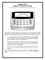
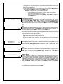
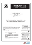
"SMART" PIR BACKLIGHTING
Keypad backlights turn on when activity is detected in front of the keypad.
The GEM-K1VPS keypad's integration of a PIR motion sensor, an adjustable blue backlight
display* and voice prompts provide a keypad that adapts to various conditions and actually
talks the user through system operation during critical events such as silencing an alarm.
• If no activity is detected in the area of the keypad for 4 minutes, the display
dims. When activity is sensed, it brightens the display along with the keypad
button backlighting. This is an excellent feature for installation in a bedroom
where a bright backlit display is not usually desired.
• If the system is in alarm and it is determined that a person is approaching the
keypad, the system turns off the siren for 15 seconds and through voice
prompts talks the user through silencing the system. If a valid code is not
entered, the siren will resume sounding.
• During entry delay, the display brightens--along with the keypad button backlighting--and voice prompts talk the User through code entry and system
disarming.
Note: "Smart" PIR Backlighting is enabled by default. In Keypad Configuration,
BACKLIGHT BRIGHTNESS = LOW and BACKLIGHT FOLLOW PIR = ON (see page 11 for
details).
* Patents Pending
3
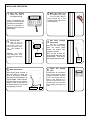
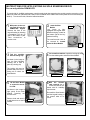
INSTALLING THE KEYPAD
Open
the
Mark the holes. Affix
1 Remove the front of
2 the template (see page
Keypad.
16), to the wall. Mark or
punch through the 4 oval
mounting holes and the wire
access opening.
the keypad housing:
Insert a screwdriver into
the two (2) slots located in
the bottom of the keypad.
Twist the screwdriver to
detach the front of the keypad housing.
4
hole in wall. Pull 4 conductor bus wire into opening.
Use template as
needed.
Wire Access
Opening
4
Next, be sure to insert the
wires through the hole in the
keypad base. Then secure
the keypad base to the wall.
6
5 Make Connections
With keypad base secured to
the wall, solder or crimp bus
wires to the keypad connector
plug using the wiring diagram as
a guide. Note: Before connecting, wires can be cut to a shorter
length to allow excess wires to
be pushed back into the access
hole opening in the wall.
UP
Pull wires through
access hole
Pull the 4 conductor
bus wire and zone wiring
from the control panel
though the access hole
opening in the wall.
Cut access hole
(4) wall an3 Install
chors and cut access
Warning: Use caution
when cutting holes. There
may be high voltage wiring
in wall.
Wire
Access
Hole
(CutinWall)
Connect Wires
Install the Keypad
Face
Double-check all connections
to the keypad using the wiring
diagram as a guide. Snap the
front of the keypad onto the
base by first inserting the 2
slots in the top onto the corresponding tabs on the base and
then snapping the bottom into
place.
Plug
Pull wires
through
access
hole
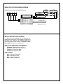
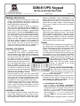
GEM-K1VPS KEYPAD WIRING DIAGRAM
GEM-P1664 Panel Terminals and EZM Harness
ZONE 3
WHITE
9
10
11 12
2.2K
ZONE 4
VIOLET
BLUE
ZONE 2
ZONE 1
2.2K
2.2K
2.2K
YELLOW
GREEN
BLACK (–)
RED (+)
ORANGE *
GRAY
BROWN (NOT USED)
x
*Keypad PIR Zone, if enabled
INSTALLING MULTIPLE KEYPADS
Up to seven (7) keypads can be installed in one
GEM-P1664 control panel. Each keypad is configured at
the factory to be "keypad #1"; all additional keypads must
have their keypad number changed via Keypad Configuration Mode (see page 10 for instructions).
GEM-P1664 REMOTE BUS TERMINALS
Terminal 9 - Red wire, positive 12VDC.
Terminal 10 - Black Wire, negative (-) GND.
Terminal 11 - Green Wire (data)
Terminal 12 - Yellow wire (data)
EZM HARNESS
Zone 1 - Orange & Gray wires
Zone 2 - Blue & Gray wires
Zone 3 - Violet & Gray wires
Zone 4 - White & Gray wires
5
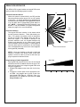
GEM-K1VPS KEYPAD PIR
The GEM-K1VPS keypad includes an integral PIR sensor
which provides the following system functions:
25’
Intrusion Protection Device
When the system is armed AWAY, the PIR provides
intrusion protection with a range of 25’ at a 90° pattern
of protection. An intruder detected in this protected area
will cause the Zone mapped to the keypad EZM Zone #1
to go into alarm with a corresponding central station report. NOTE: If keypad PIR Intrusion Protection is not
desired, it may be disabled in Keypad Configuration
Mode (see page 10 for more information).
Top
View
90º
Presence Detection
The keypad PIR also includes 2 side beams which
provide presence detection. These side beams provide a 170° pattern of protection, which is intended to
prevent an intruder from walking along the wall towards the keypad. If an intruder is detected in the
presence detection zone, the keypad backlight may
brighten and depending on the system state, certain
voice messages may be prompted. In cases where an
extremely large signal is generated in the Anti-Tamper
zone, an actual alarm may occur on the zone mapped to
the keypad PIR (if enabled).
Intrusion Protection
Beams
Presence Detection Beams
5º
NOTE: If there are windows on the wall on which the
keypad is mounted, they should remain closed while
system is armed in order to prevent a draft from tripping the presence detection beams.
Programming to Enable Keypad PIR
The keypad PIR occupies the first zone of the integral
EZM when the PIR is enabled; therefore be sure to enable the first zone of the integral keypad EZM when
using the keypad PIR.
1. Enable EZM Address other than (00) for this keypad.
2. Program the control panel for the appropriate number EZM. Also program the 1st zone of each integral keypad EZM (Zone 9 = EZM #1, Zone 13 =
EZM #2, etc). as a STAY zone and also as an Exit/
Entry Follower zone.
6
Side View
5’
5’
10’
15’
20’
25’
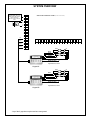
SYSTEM OVERVIEW
16 VAC 20 VA
TRANSFORMER TRF12 (OR
EQUIVALENT SEE WI1811)
Class 2 Transformer.
DO NOT connect to switched
outlet.
GEM-P1664 CONTROL PANEL (See WI1811 for more information)
1
2
+
BELL
+3
–
GND
–4
2.2K
2.2K EOLR
+5
–6
–7
–8
– 14
+15
+16
– 17
+18
+19
– 20
+21
– 22
+23
+24
+25
26
27
28
29
12
YELLOW
+13
11
GREEN
– 10
BLACK
+9
RED
2.2K
ZONE 4
WHITE
VIOLET
BLUE
2.2K
ZONE 3
2.2K
ZONE 2
2.2K
ZONE 1
ORANGE *
GRAY (ZONE GROUND)*
BROWN (NOT USED)
X
*Keypad PIR Zone, if enabled
Keypad #1
2.2K
ZONE 4
WHITE
VIOLET
BLUE
2.2K
ZONE 3
2.2K
ZONE 2
2.2K
ZONE 1
ORANGE *
GRAY (ZONE GROUND)*
BROWN (NOT USED)
X
*Keypad PIR Zone, if enabled
Keypad #2
* Any of the 3 gray wires may be used as a zone ground.
7
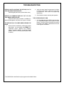
TROUBLESHOOTING
KEYPAD LIGHTS (ON FRONT OF KEYPAD) FAIL TO
TURN ON WHEN POWER APPLIED
Check Keypad power wires (red and black wires).
KEYPAD LCD WINDOW DISPLAYS "OUT OF SYSTEM" WHEN POWER APPLIED
Green wire either open or shorted. In addition, if a
system trouble appears, the yellow wire is open or shorted.
THE KEYPAD FAILS TO CHIME* WHEN OPENING THE
DOOR
2. Verify the control panel is programmed for Chime
to function in the system. Also verify Chime Time
is programmed. See WI1810 for programming
instructions).
3. Check the door contact continuity and operation.
THE SYSTEM DOES NOT ARM
1. On the keypad, the green READY light should be
on. If the READY light is not on, there is a zone
faulted. All zones must be secured for the system
to be able to arm. Note: Faulted Zones will scroll
in the keypad LCD Window.
1. Be sure Chime is enabled by entering the Keypad
Menu Mode. On the keypad, press MENU until
"Deactivate Chime" appears, thus indicating
Chime is currently enabled. If "Activate Chime"
appears, Chime is currently disabled (press YES
to enable).
* The GEM-P1664 Control Panel may be programmed to disable Chime.
8
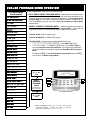
DEALER PROGRAM MODE OVERVIEW
EASY MENU DRIVEN
PROGRAM MODE
Dealer Program Mode comprises two operational states:
•
EASY MENU DRIVEN PROGRAM MODE - Used with new "out of the box" panels (or "Cold Started" panels, see address 2286), this mode allows the dealer to customize the factory panel program to best suit the installation. The Easy Menu-Driven
Program Mode is a menu-driven utility that prompts the installer to configure the system. Press C at any time to exit, thus entering Direct Address Program Mode,
# of Zns in Area 1*
EZ Zone Doubling Enabled?*
Fire Zones*
detailed below.
2-Wire Fire Zns*
Report All Zones To Central
Station?*
•
DIRECT ADDRESS PROGRAM MODE - Additional programming changes, if
necessary, can be made in the Direct Address Program Mode. In this mode, the
programming address is accessed directly and re-configured by the installer.
Exit/Entry Zones*
Interior Zones*
TYPICAL USER: Dealers / Installers only.
24 Hour Zones*
TYPICAL INTERFACE: an GEM-K1VPS keypad.
Chime Zones*
HOW TO ENTER: Press the factory-installed default Dealer Code:
456789R. Press AWAY ("NO") until
Chime 2 Zones*
Exit/Entry 2 Zns*
50mS Loop Zones*
Aux Output Zones*
Sensor Watch Zns*
"ACTIVATE PROGRAM Y/N" appears on LCD screen. Press STAY ("YES") to
enter the Easy Menu-Driven Program Mode. See Programming Instructions
(WI1810) for additional information regarding the Easy Menu Driven Program
Mode.
To exit, press C to enter Direct Address Program Mode and press C
once again to exit Dealer Program Mode.
KP Sndr Alrm Zns*
Auto Byp REnt Zn*
Enable No EOLR Zones*
Enable Telco Line Test?*
Enable Burg Out Chirp?*
Enable SIA-CP01*
# Area 1 Keypads
TO EXIT PRESS
C AT ANY
TIME
Central Phone #
Central Station Account #
See WI for Info Rcvr Format
Enter user code
ZN# XMIT#+CS P
KF A XMIT#+CS 0P
DIRECT
ADDRESS
PROGRAM
MODE
Scroll Down
Yes
Scroll Up
No
Exit
(see WI1810 for
more information
For the GEM-K1VPS Keypads
TO EXIT PRESS
C AT ANY
.
01- (ZONE DESCRIPTIONS)
Enter Date
TIME
Enter Time
Dealer Code
Test Timer
* Initial Configuration Only (new or memory cleared panel);
suppressed thereafter.
Normal entry mode for previously
programmed panel starts at "# AREA 1 KEYPADS".
9
KEYPAD CONFIGURATION MODE
This section concentrates on configuring the GEM-K1VPS keypad.
KEYPAD INSTALLATION
Each keypad must be assigned an address number (1-7). Each
keypad requires its own configuration procedure because all Keypad Configuration Mode changes are retained within each individual keypad only (see CONFIGURING THE KEYPADS, below). At
least one (1) keypad must be used; only one is required for a single-area Commercial Burglary installation.
CONFIGURING THE KEYPADS
Keypad Configuration Mode provides an exclusive set of menu
options used to change the properties of each individual keypad to
suit each installation.
•
•
TYPICAL USER: Dealers and installers only.
TYPICAL INTERFACE: Keypad only.
Each keypad must be configured for the following items: Keypad
Beep, Entry Sounder, Keypad Address, EZM Address, Zone Response, Backlight Brightness, Tamper Detect, PIR, Backlight Follow PIR and SIREN.
To enter the Keypad Configuration Mode:
1. You can either move jumper JP1 (located in the center of
the GEM-P1664 control panel board) from pins 1-2 (top two
"NORMAL") to pins 2-3 (bottom two
"KEYPAD CONFIGURE") --or-- you can
NORMAL
press keypad buttons 1, 2 and 3
KEYPAD
simultaneously. NOTE: See wiring
CONFIGURE
diagram at the end of this manual
and the jumper configuration diaGEM-P1664 Panel Jumper
Configuration diagram
gram at right.
2. After a short delay, the display will
read "OUT OF SYSTEM XX", where "XX" indicates the keypad address.
3. Press "11123" and press MENU to for 2 seconds on the
installed keypad to enter Keypad Configuration Mode and
proceed as follows. (Repeat the following procedure for all
keypads in the system).
Once the Keypad Configuration Mode is accessed, all
messages will display in the order shown below.
Keypad Beep
KEYPAD BEEP
ON
Upon entering the Keypad Configuration Mode, "KEYPAD BEEP ON" is displayed, indicating
that the tactile beep, which sounds when any button is pressed, is on. To turn off the tactile
beep, press the ENTER button; to turn the tactile beep again, press ENTER. Default is beep
"ON". Press MENU to continue or press RESET to exit.
Entry Sounder
ENTRY SOUNDER
ON
To turn off the keypad entry sounder during entry time, press the ENTER button; to turn on
the entry sounder, press ENTER again. Default is sounder "ON". Press MENU to continue
or press RESET to exit.
Keypad Address
KEYPAD ADDRESS
01
If more than one keypad is installed, each must be assigned a unique keypad address--that
is, no two keypads may be numbered alike. Keypads must be numbered consecutively
(missing numbers are not permitted).
To assign the keypad number, proceed as follows:
1. At the keypad, press the number keys (valid entries are "01"–"07") and press ENTER.
For example, for keypad #2, press "02" and then press ENTER to save. Note: Default
entry is "01". An entry of zero-zero ("00") will not be accepted.
2. Press MENU to continue or press RESET to exit.
EZM Address
EZM ADDRESS
00
Zone Response
ZONE RESPONSE
00
10
The keypad's internal EZM (Expansion Zone Module) may be utilized to provide four additional wired zones. Whether used alone or in conjunction with optional GEM-EZM series
modules or other keypad EZMs, it must be assigned a unique address (or Group number)
similar to its keypad address. If no other EZMs are to be used, designate the keypad as
Group "01" at the "EZM ADDRESS 00" display. In multiple-EZM systems, enter an assigned
group number "01" through "14" and press ENTER. For example, for EZM #3, press "03"
and then press ENTER to save. Each EZM must have a unique assigned Group number,
starting with "01" and proceeding consecutively. Default is "00". Press MENU to continue or
press RESET to exit.
The normal (default) loop response of each keypad EZM expansion zone is 750mS. Changing this response time may be required when some devices require a faster loop response,
such as Glass Break sensors, and thus 50ms can be programmed. Do not program in UL
installations (UL requires 750ms be programmed). The response time of any zone can be
reduced to 50mS as follows.
1. Of the following, circle the number(s) in parentheses associated with the zone(s) to be
changed: Zone 1=(1); Zone 2=(2); Zone 3=(4); Zone 4=(8).
2. Add up the circled numbers.
3. At the keypad, enter the sum as a two-digit number "01" through "15". Note: Default
entry is "00". Press MENU to continue or press RESET to exit.
Example: Change Zones 2, 3 and 4 to 50mS response.
1. Circle numbers for Zones 2, 3 and 4: Circle (2), circle (4) and circle (8).
2. Add up the circled numbers: 2 + 4 + 8 = 14.
3. Enter "14" at the keypad and press ENTER. Press MENU to continue or
press RESET to exit.
BACKLIGHT
BRIGHTNESS
Backlight Brightness
LOW
To adjust the brightness of the LCD window, press YES to increase and NO to decrease.
Selections are LOW, MED and HIGH. Note: Selections repeat if either the YES or NO buttons are pressed repeatedly. Default is "LOW". If intending to enable "Backlight Follow
PIR" (future menu item), set this entry to "LOW". Press MENU to continue or press RESET
to exit.
PIR
PIR
NO
When disabled, the PIR will NEVER trigger an alarm. When enabled, the PIR will activate an
alarm ONLY when armed Away. Press ENTER to toggle between enable and disable. Default is "NO" (disabled). Press MENU to continue or press RESET to exit.
When enabled, the following additional keypad configuration options and panel programming
must be performed to ensure desired operation:
1. Enable EZM address (other than "00") for this keypad.
2. Program the panel for the appropriate number of EZM's and also program zone 1 of this
EZM (Zone 9 if EZM1, Zone 13 if EZM 2, etc.) as a STAY zone and as an E/E Follower
Zone.
BACKLIGHT
FOLLOW PIR
Backlight Follow PIR
ON
Turns keypad backlight on when person is detected in front of the keypad (default). To turn
off this backlight, press ENTER; to turn on the backlight, press ENTER again. Keypad Configuration Mode entry Backlight Brightness should be set to "LOW". Default is "ON". Press
MENU to continue or press RESET to exit.
Siren
SIREN
ON
When enabled, the integral siren will follow the control panel Bell output. To comply with UL
Audibility requirements for sole sounding device, see page 13. To disable the siren, press the
ENTER button; to enable the siren, press ENTER again. Default is "ON". Press MENU to
continue or press RESET to exit.
Tamper Detect
TAMPER DETECT
NO
Enable or disable the monitoring of the Tamper switch located on the keypad circuit board.
The tamper monitors both the front keypad case and the rear keypad mounting surface. If
the front case is opened or if the keypad is removed from the wall, the tamper switch is activated (displays Keypad Tamper system trouble "E11-XX", where XX is the address of the
keypad detected by the panel). To disable the Tamper switch, press the ENTER button; to
enable, press ENTER. Default is "NO" (disabled). Press MENU to continue or press RESET
to exit.
To exit Keypad Configuration Mode, press RESET.
11
KEYPAD MENU MODE
The keypad can provide access to a wide assortment of utility functions, each displayed on the keypad LCD window in a prompting
“YES/NO” format. This keypad menu is not necessary for panel
programming, but is included here for reference.
TYPICAL USER: Homeowner.
TYPICAL INTERFACE: Keypad only.
HOW TO ENTER: At the installed keypad, press a valid user code
and press MENU to enter. All messages in the Keypad Menu
Mode are listed below, but some messages may not appear in
the keypad display for certain user code types; if the required
condition is not present; or if the GEM-P1664 control panel is
configured in such a way as to remove the message from this
Menu. For example, “DISPLAY ZN FAULTS Y/N” will only display if zones are faulted.
ing a different set of messages to appear:
• Entering a standard User Code or pressing R
only: Displays those standard functions needed for normal operation.
• Entering a User Code enabled by the Dealer for User
Program Mode before pressing R:
Displays the
standard functions described above and additional higher
security functions.
• Entering the Dealer Program Code before pressing
R: Displays all functions.
With each message, press YES to proceed with the change or
NO to skip to the next selection. Note: Highlighted messages
are sub-menu selections.
In the Keypad Menu Mode, there are three levels, each allowALL MESSAGES IN MENU
NOTES
DISPLAY OPEN ZONES Y/N
Will display open zones only when a zone is faulted.
DISPLAY ZN BYPASSED Y/N
Scrolls list of bypassed zones (cannot unbypass from this selection).
DISPLAY ZN DIRECTORY Y/N
Allows you to scroll through zone descriptions and also allows individual zones to be bypassed. Press
NEXT or PRIOR to scroll through zone list.
ACTIVATE SIREN TEST Y/N
Press YES to activate burg relay output and integral siren (if enabled) for 2 seconds.
DISPLAY FIRE ALARM Y/N
Displays list of shorted fire zones only when a fire alarm is tripped.
DISPLAY FIRE TRBL Y/N
Displays list of troubled fire zones only when a fire alarm is tripped.
ACTIVATE CHIME Y/N
When activated, this selection reads "DEACTIVATE CHIME Y/N".
RESET SYSTEM TBL Y/N
This message appears if a trouble is found.
ACTIVATE FAULT FIND Y/N
Activates Fault Find mode. The Dealer Program Code must be entered for this feature to appear.
Test Timer must be programmed to report for this option to appear. If it is desired NOT to report Test Timer
to the Central Station, but you still wish this option to appear in this menu, do NOT enable Test Timer in the
PCD Windows Scheduler screen (or via Direct Address programming).
Displays alarm events in log. The User or Dealer Program Code must be entered for this feature to appear.
Use NEXT and PRIOR to scroll forward or backward through list.
Displays events of all types in log. The User or Dealer Program Code must be entered for this feature to
appear. Use NEXT and PRIOR to scroll forward or backward through list.
Displays fire events in log. The User or Dealer Program Code must be entered for this feature to appear.
Use NEXT and PRIOR to scroll forward or backward through list.
Displays open and closing events in log. The User or Dealer Program Code must be entered for this feature
to appear. Use NEXT and PRIOR to scroll forward or backward through list.
Displays system events in log. The User or Dealer Program Code must be entered for this feature to appear. Use NEXT and PRIOR to scroll forward or backward through list.
ACTIVATE DIALER TEST Y/N
DISPLAY ALARM LOG Y/N
DISPLAY TOTAL LOG Y/N
DISPLAY FIRE LOG Y/N
DISPLAY OP/CL LOG Y/N
DISPLAY SYSTEM LOG Y/N
The User or Dealer Program Code must be entered for this feature to appear.
AUTO ARM IN 1-4 HRS 0
Also called "User Program Mode". See Keypad User Manual for more information. The User or Dealer
Program Code must be entered for this feature to appear.
Allows modem connection with PC Preset software. The User or Dealer Program Code must be entered
for this feature to appear.
ACTIVATE PROGRAM Y/N
ACTIVATE DOWNLOAD Y/N
CHANGE KEYPAD BEEP VOLUME
12
CHANGE VOICE VOLUME
Y/N
ACTIVATE PIR TEST
Y/N
Y/N
The User or Dealer Program Code must be entered for this feature to appear.
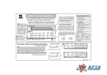
INSTRUCTIONS FOR APPLICATIONS AS SOLE SOUNDING DEVICE
For use only with the GEM-K1VPS
To comply with UL Audibility requirements, a small acoustic cloth that covers the siren module must be removed or a compatible UL Listed siren (Wheelock AH-12WP) must be installed on the GEM-P1664 control panel bell circuit terminals (see
WI1811). To remove the cloth, follow the instructions below.
power to the con1 With
trol panel off, open the
the Siren
2 Locate
Module.
GEM-K1VPS keypad.
Remove the front of the
keypad housing by inserting
a screwdriver into the (2)
slots in the bottom of pad.
Twist screwdriver to
remove cover.
The image at right
highlights the keypad Siren
Module and plug, located at
the bottom right of the keypad rear housing.
The small acoustic cloth to
be removed is located
under the Siren Module.
As shown in the image at
right, the Siren Module's
retaining tab is held in
place by a locking clip.
retaining tab
locking clip
Insert screwdriver here...
...and push clip away from the tab
the acoustic
6 With
cloth removed, the si-
the Siren Module
5 Lift
to expose the acous-
ren dB level will be consistent with UL Audibility
requirements.
tic cloth.
As shown in the image at
right, gently lift the Siren
Module, exposing the
acoustic cloth.
Remove cloth and store in
a safe place to be re-used if
needed.
Siren
Module
a small screwdriver to push the locking clip away
4 Use
from the retaining tab to unlock the Siren Module.
the retaining
3 Find
tab and locking clip.
The locking clip must be
pushed away from the retaining tab to unlock the
Siren Module.
Siren Plug
Re-install the Siren Module
and the keypad housing in
the reverse order of removal.
acoustic cloth
acoustic cloth removed
13
NOTES
14
THIS PAGE INTENTIONALLY LEFT BLANK
15
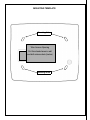
MOUNTING TEMPLATE
Mounting Holes
Wire Access Opening
Cut this shaded area in wall
and drill antenna hole (below)
Mounting Holes
16