1
A NovAtel Precise Positioning Product
Inertial Explorer
USER GUIDE
OM-20000106
Rev 5
Inertial Explorer User Guide
Publication Number: OM-20000106
Revision Level: 5
Revision Date: 2008/02/15
This manual reflects Inertial Explorer software version 8.10.
Proprietary Notice
Information in this document is subject to change without notice and does not represent a commitment on the part of
NovAtel Inc. The software described in this document is furnished under a licence agreement or non-disclosure
agreement. The software may be used or copied only in accordance with the terms of the agreement. It is against the
law to copy the software on any medium except as specifically allowed in the license or non-disclosure agreement.
No part of this manual may be reproduced or transmitted in any form or by any means, electronic or mechanical,
including photocopying and recording, for any purpose without the express written permission of a duly authorized
representative of NovAtel Inc.
The information contained within this manual is believed to be true and correct at the time of publication.
NovAtel, Inertial Explorer, GrafNav, GrafNet, GPSolution, ProPak, OEMV, OEM4, and RT-2 are registered
trademarks of NovAtel Inc.
Waypoint, SPAN Technology, DL-4plus, ProPak-G2plus, ProPak-LBplus, PAC, AdVance, and RT-20 are trademarks
of NovAtel Inc.
All other product or brand names are trademarks of their respective holders.
© Copyright 2008 NovAtel Inc. All rights reserved. Unpublished rights reserved under
International copyright laws. Printed in Canada on recycled paper. Recyclable.
2
Inertial Explorer 8.10 User Guide Rev 5
Table of Contents
Table of Contents
Table of Contents
3
Foreward ............................................................................................................................................... 9
Software License ................................................................................................................................ 13
Warranty ............................................................................................................................................. 15
Terms and Conditions ......................................................................................................................... 17
1 Inertial Explorer
19
1.1 Overview of Inertial Explorer.......................................................................................................... 19
1.2 Getting Started with Inertial Explorer ............................................................................................. 19
1.3 File Menu ....................................................................................................................................... 22
1.3.1 New Project ......................................................................................................................... 22
1.3.2 Add Master File(s) ............................................................................................................... 22
1.3.3 Add Remote File ................................................................................................................. 22
1.3.4 Add IMU File ........................................................................................................................ 23
1.3.5 Convert................................................................................................................................. 23
1.3.6 Removing Processing Files.................................................................................................. 23
1.4 View Menu ..................................................................................................................................... 24
1.5 Process Menu................................................................................................................................ 24
1.5.1 Process IMU (loosely coupled) ........................................................................................... 24
1.5.2 Process TC (tightly coupled IMU) ........................................................................................ 37
1.5.3 Combine and Smooth ......................................................................................................... 38
1.5.4 Solve Boresighting Angles .................................................................................................. 40
1.5.5 Loading IMU Solutions ......................................................................................................... 43
1.6 Settings Menu ............................................................................................................................... 44
1.6.1 IMU Settings ........................................................................................................................ 44
1.7 Output Menu.................................................................................................................................. 44
1.7.1 Plot Results ......................................................................................................................... 44
1.7.2 Export Wizard....................................................................................................................... 45
1.8 Tools Menu .................................................................................................................................... 45
1.9 Interactive Windows....................................................................................................................... 46
1.10 Processing Window ..................................................................................................................... 46
1.11 Help Menu ................................................................................................................................... 46
1.11.1 Help Topics ....................................................................................................................... 46
1.11.2 The Waypoint Products Group’s Web Page ..................................................................... 46
1.11.3 About Inertial Explorer........................................................................................................ 47
2 Conversion Utilities
49
2.1 Raw IMU Data Converter............................................................................................................... 49
2.1.1 Waypoint IMU Data Conversion........................................................................................... 49
2.1.2 Creating / Modifying a Conversion Profile ........................................................................... 50
2.1.3 Sensor Orientation Settings ................................................................................................. 51
2.1.4 Decoder Settings.................................................................................................................. 51
3 Data and File Formats
53
3.1 Data Formats ................................................................................................................................. 53
3.1.1 NovAtel’s SPAN Technology................................................................................................ 53
3.2 File Formats................................................................................................................................... 54
3.2.1 IMR File................................................................................................................................ 54
3.3 Output Files ................................................................................................................................... 56
3.3.1 FIL/RIL/FTL/RTL Files ......................................................................................................... 56
3.3.2 FIM/RIM/FTM/RTM Files...................................................................................................... 57
Inertial Explorer 8.10 User Guide Rev 5
3
Table of Contents
3.3.3 BIF/BIR/BTF/BTR Files ........................................................................................................ 58
4 FAQ and Tips
61
4.1 Overview of FAQ and Tips............................................................................................................. 61
4.2 How are Inertial Explorer and coordinate frames related? ............................................................ 61
4.2.1 What is an inertial frame?..................................................................................................... 61
4.2.2 What is a computation frame? ............................................................................................. 62
4.2.3 What is a navigation frame? ................................................................................................ 62
4.2.4 What is a body frame? ........................................................................................................ 62
4.3 What should I know about inertial processing? ............................................................................. 63
4.3.1 Why are error models so important? .................................................................................... 65
4.3.2 Why is alignment so important? .......................................................................................... 66
4.3.3 What is static alignment? .................................................................................................... 66
4.3.4 What is kinematic alignment?............................................................................................... 67
4.3.5 What is IMU Kalman filtering? .............................................................................................. 67
4.3.6 What is Kalman filter smoothing? ........................................................................................ 68
4.4 What do I need to know about Boresighting? ................................................................................ 69
4.4.1 Why is boresighting needed? ............................................................................................... 69
4.4.2 How does the boresighting module work? ........................................................................... 69
4.4.3 What are omega, phi and kappa? ........................................................................................ 69
4.4.4 Can I use this module to boresight my pushbroom or laser data? ...................................... 70
4.4.5 Does this module come with a bundle adjustment? ............................................................ 70
4.4.6 What do I need to get started? ............................................................................................ 70
4.4.7 What if my photo angles are not omega primary, phi secondary and kappa tertiary? ........ 70
4.4.8 Where is my boresighting file data stored? ......................................................................... 70
4.4.9 What if Inertial Explorer does not support my grid system? ................................................ 70
4.4.10 What mathematical equations are used by boresighting?.................................................. 71
4.5 How do I decode raw inertial data? ............................................................................................... 72
4.5.1 How do I deal with offsets between IMU sensor frame and vehicle body frame? ............... 72
4.6 How do I deal with an upside down IMU?...................................................................................... 73
4.7 How do I deal with unknown lever arm offsets from a GNSS antenna to an IMU centre? ............ 73
4.8 How important is error model tuning?............................................................................................ 74
4.8.1 How do I build my own error model?.................................................................................... 75
4.8.2 How do I know if my error model is working?....................................................................... 75
4.9 How can I use the alignment of the IMU? ..................................................................................... 76
4.9.1 How much static alignment data do I need? ....................................................................... 76
4.9.2 How do I find start/end times for the IMU alignment? ......................................................... 76
4.9.3 How can I use kinematic alignment?.................................................................................... 77
4.9.4 How can I use transfer alignment?....................................................................................... 77
4.10 Processing Tips ........................................................................................................................... 77
4.10.1 What tolerances should be used for GNSS updates to the IMU? ...................................... 77
4.10.2 How do I use ZUPTs? ....................................................................................................... 78
4.10.3 When should I use GNSS velocity and heading updates? ................................................ 78
4.10.4 I only have a single point solution (.FSP File), is this okay? ............................................. 78
4.10.5 Does 10 Hz GNSS data help? ........................................................................................... 78
4.10.6 What should I look for while the IMU data is processing?.................................................. 79
4.11 Tightly Coupled Processing Tips ................................................................................................. 79
4.11.1 What is the difference between loosely-coupled and tightly-coupled processing? ............ 79
4.11.2 How do I engage loosely-coupled and/or tightly-coupled processing
in Inertial Explorer? ........................................................................................................... 80
4.11.3 How can I differentiate between the files created by loosely-coupled and
tightly-coupled processing? ............................................................................................... 80
4.11.4 Should I use loosely-coupled or tightly-coupled processing?............................................. 81
4.12 Data Analysis Tips ....................................................................................................................... 81
4
Inertial Explorer 8.10 User Guide Rev 5
Table of Contents
4.12.1 How is the IMU quality (Q) number different from the GNSS Q number?.......................... 81
4.12.2 What plots should I examine after IMU Processing? ........................................................ 82
4.12.3 How do I smooth and export data? ................................................................................... 82
Appendix A Appendix A
83
Appendix A Summary of Commands................................................................................................... 83
Index
Inertial Explorer 8.10 User Guide Rev 5
87
5
Table of Contents
6
Inertial Explorer 8.10 User Guide Rev 5
List of Figures
Body Frame Definition for Lever Arm Offset ............................................................................................. 29
Coordinate Frames in Inertial Explorer ..................................................................................................... 61
Body Frame Definition ............................................................................................................................... 62
IMU Camera .............................................................................................................................................. 65
Inertial Explorer 8.10 User Guide Rev 5
7
List of Tables
IMU Plots ................................................................................................................................................... 44
Binary Structure of Raw Data .................................................................................................................... 53
Pitch and Yaw Differences ........................................................................................................................ 68
Inertial Explorer Extensions for Output Files ............................................................................................. 80
Inertial Explorer 8.10 User Guide Rev 5
8
Foreword
Foreward
Congratulations!
Congratulations on purchasing a Waypoint Products Group’s software package.
Inertial Explorer is a Windows-based suite of programs that provide GNSS (Global Navigation Satellite System) data
post-processing. This manual will help you install and navigate your software.
Scope
This manual contains information on the installation and operation of Waypoint Products Group’s Inertial Explorer
software package. It allows you to effectively navigate and post-process GNSS, IMU (Inertial Measurement Unit)
and wheel sensor data. It is beyond the scope of this manual to provide details on service or repair, please see the
Conventions and Customer Service section on this page for customer support.
How to use this manual
This manual is based on the menus in the interface of Waypoint’s software. It is intended to be used in conjunction
with the most recent revision of the GrafNav/GrafNet User Guide found at http://www.novatel.com/products/
waypoint_grafnav.htm and the corresponding version of Waypoint’s Inertial Explorer software.
Prerequisites
To run Waypoint software packages, your personal computer must meet or exceed this minimum configuration:
Operating System
Windows 2000, XP or Vista.
Hard Drive Space
55 MB of available space on the hard disk.
Processor
A Pentium or Xeon processor is required. Simultaneous forward/reverse processing is possible on dual CPU and
Xeon systems. At least 256 MB of RAM is also required.
Although previous experience with Windows is not necessary to use Waypoint software packages, familiarity with
certain actions that are customary in Windows will assist in the usage of the program. This manual has been written
with the expectation that you already have a basic familiarity with Windows.
Conventions and Customer Service
This manual covers the full performance capabilities of Inertial Explorer 8.10 data post processing software. Simple
conventions in this manual include the following:
This is a notebox that contains important information before you use a command or log, or to give
additional information afterwards.
This manual contains shaded boxes on the outside of the pages. These boxes contain procedures, screen
shots, tables and quick references.
If the software was purchased through a vendor, please contact them for support. Otherwise, for software updates and
customer service, contact NovAtel’s Waypoint Products Group using the following methods:
Call: (403) 295-4900
Fax: (403) 295-4901
Email: wpsupport@novatel.com
Web: http://www.novatel.com/
Write:NovAtel Inc.
Customer Service Department
1120-68 Avenue NE
Calgary AB
Canada, T2E 8S5
Inertial Explorer 8.10 User Guide Rev 5
9
What’s New!
Inertial Explorer - Version 8.10
Version 8.10 uses NovAtel’s AdvanceTM RTK (ARTK) on-the-fly (OTF) engine that fixes carrier phase ambiguities
faster and at longer distance than GrafNav’s KAR algorithm. ARTK also has fewer failed fixes than KAR and
produces a lower separation between forward and reverse trajectories.
PPP processing accuracy has been improved by up to 40% by refining the solution with an additional processing pass
and by applying higher order corrections.
For high altitude or long distance data sets much of the tropospheric error can be removed by the addition of a
Kalman filter bias state. Such methods have often had problems in differential mode, and we have solved this
problem by using GrafNav’s PPP processor to compute the tropospheric bias trajectory for each base station.This tool
can also be used to check the base station coordinates.
In multi-base mode, base stations can be rejected if the base-remote distance is longer than a user set tolerance.
Satellites with low C/N0 can be rejected from the filter.
Version 8.10 also includes an improvement on automated Zero Velocity Update (ZUPT) detection.
User interface improvements:
The map window and plot windows can be zoomed in and out with the mouse wheel and maps can be displayed with
a white background and can be copied to the clipboard. In GrafNav and GrafNav Batch users can create groups of
plots that can be displayed using one operation. Multiple plots can also be selected and for all plots, time and y-axis
ranges can be applied from one plot to others.
For GrafNav, there is now an API/DLL that has many of the same capabilities as command line the command line
interface, but the calling application is provided complete feedback during processing and exporting. The export
wizard has improved time zone selection for local times and ½ hour time zones are now supported.
A variety of HTML reports can now be generated including from the command line and API. GrafNav command line
(and API) permits users to save all processing messages to a single log for later review. GrafNav and GrafNet project
data can be automatically displayed in Google Earth.
In GrafNet, the network adjustment can now execute automatically on completion of processing and it now supports
station names as long as 12 characters.
The Favorites Manager has been significantly improved such that nearby stations are shown in a list along with the
distance and datum. Furthermore, antenna attributes can be stored and selected.
There is now support for stereographic map projection and Processing files can now be deleted recursively in
subdirectories from a specified path.
Version 8.10 has full support for ITRF2005 and improved software registration
Decoder improvements:
• For Leica 1200, better handling of outdated ephemerides
•
For NovAtel OEMV, BESTPOS trajectory can be exported to a GrafNav compatible format
•
For Trimble DAT, better handling of station names and more than 12 satellites
In GPB2RIN, command line version is now available and some bug fixes have been implemented.
10
Inertial Explorer 8.10 User Guide Rev 5
Inertial Explorer - Version 8.00
The major new addition for Version 8.00 is Tightly Coupled (TC) processing. It uses GPS carrier phase to limit error
where satellite tracking is limited or variable (even if only 2 or 3 satellites are visible). Another important
enhancement is the addition of a new API to permit much expanded automated processing. The new API now
provides complete feedback and permits calling application to better control processing progress.
Other improvements include:
•
Non-integer data rates now fully supported
•
Improved processing and back smoothing of low or variable data rate inertial data
•
Better support in back smoother and IMU processing for data SPANning the GPS week crossover
•
Binary output (from processing engine) can now be written at a lower data rate than processing
interval
•
Local time can now be exported for ½ hour time zones
•
Text names of time zones can be specified.
•
X and Y axes ranges from one data plot can be transferred to others
•
Better display of larger IMU time gaps in File Data Coverage Plot
•
Ability to utilize real-time position such as, OmniSTAR, SBAS, RTK, from BESTGPS position
record (from SPAN) in inertial processor
•
Events from SPAN MARKTIME2 can be exported to a separate file permitting support for dual
event marks
•
CUPTs and ZUPTs can now be loaded from a file.
Inertial Explorer – Version 7.80
Version 7.80 of Inertial Explorer contains all of the IMU processing improvements introduced with IE Version 7.70
combined with the new GNSS capabilities found in GrafNav/GrafNav Version 7.80. This includes the ability to
process precise point positioning (PPP) and enhanced GLONASS carrier phase positioning. The following additions
are also available:
•
PPP trajectories can now be used to update IMU processing
•
Converting iMAR raw IMU data is much more streamlined
•
Improved error models for iMAR
•
Improved reverse processing resulting in 30% less noise
Inertial Explorer 8.10 User Guide Rev 5
11
12
Inertial Explorer 8.10 User Guide Rev 5
Software LicenseSoftware License
BY INSTALLING, COPYING, OR OTHERWISE USING THE SOFTWARE PRODUCT, YOU AGREE TO
BE BOUND BY THE TERMS OF THIS AGREEMENT. IF YOU DO NOT AGREE WITH THESE TERMS
OF USE, DO NOT INSTALL, COPY OR USE THIS ELECTRONIC PRODUCT (SOFTWARE,
FIRMWARE, SCRIPT FILES, OR OTHER ELECTRONIC PRODUCT WHETHER EMBEDDED IN THE
HARDWARE, ON A CD OR AVAILABLE ON THE COMPANY WEB SITE) (hereinafter referred to as
"Software").
1. License: NovAtel Inc. ("NovAtel") grants you a non-exclusive, non-transferable license (not a sale) to use the
software subject to the limitations below. You agree not to use the Software for any purpose other than the due
exercise of the rights and licences hereby agreed to be granted to you.
2. Copyright: NovAtel owns, or has the right to sublicense, all copyright, trade secret, patent and other proprietary
rights in the Software and the Software is protected by national copyright laws, international treaty provisions and all
other applicable national laws. You must treat the Software like any other copyrighted material and the Software may
only be used on one computer at a time You may not copy the product manual or written materials accompanying the
Software. No right is conveyed by this Agreement for the use, directly, indirectly, by implication or otherwise by
Licensee of the name of NovAtel, or of any trade names or nomenclature used by NovAtel, or any other words or
combinations of words proprietary to NovAtel, in connection with this Agreement, without the prior written consent
of NovAtel.
3. Patent Infringement: NovAtel shall not be liable to indemnify the Licensee against any loss sustained by it as the
result of any claim made or action brought by any third party for infringement of any letters patent, registered design
or like instrument of privilege by reason of the use or application of the Software by the Licensee or any other
information supplied or to be supplied to the Licensee pursuant to the terms of this Agreement. NovAtel shall not be
bound to take legal proceedings against any third party in respect of any infringement of letters patent, registered
design or like instrument of privilege which may now or at any future time be owned by it. However, should NovAtel
elect to take such legal proceedings, at NovAtel's request, Licensee shall co-operate reasonably with NovAtel in all
legal actions concerning this license of the Software under this Agreement taken against any third party by NovAtel
to protect its rights in the Software. NovAtel shall bear all reasonable costs and expenses incurred by Licensee in the
course of co-operating with NovAtel in such legal action.
4. Restrictions:
You may not:
(a) use the software on more than one computer simultaneously with exception of the Windows and WinCE data
logging software which may be copied and used for each GPS receiver collected data simultaneously;
(b)distribute, transfer, rent, lease, lend, sell or sublicense all or any portion of the Software without the written
permission of NovAtel;
(c) alter, break or modify the hardware protection key (dongle) thus disabling the software copy protection;
(d)modify or prepare derivative works of the Software;
(e) use the Software in connection with computer-based services business or publicly display visual output of the
Software;
(f) implement DLLs and libraries in a manner that permits automated internet based post-processing (contact
NovAtel for special pricing);
(g )transmit the Software over a network, by telephone or electronically using any means (except when downloading
a purchased upgrade from the NovAtel web site); or
(h)reverse engineer, decompile or disassemble the Software.
Inertial Explorer 8.10 User Guide Rev 5
13
Software License
You agree to keep confidential and use your best efforts to prevent and protect the contents of the Software
from unauthorized disclosure or use.
5. Term and Termination: This Agreement and the rights and licences hereby granted shall continue in force in
perpetuity unless terminated by NovAtel or Licensee in accordance herewith. In the event that the Licensee shall at
any time during the term of this Agreement: i) be in breach of its obligations hereunder where such breach is
irremediable or if capable of remedy is not remedied within 30 days of notice from NovAtel requiring its remedy;
then and in any event NovAtel may forthwith by notice in writing terminate this Agreement together with the rights
and licences hereby granted by NovAtel. Licensee may terminate this Agreement by providing written notice to
NovAtel. Upon termination, for any reasons, the Licensee shall promptly, on NovAtel's request, return to NovAtel or
at the election of NovAtel destroy all copies of any documents and extracts comprising or containing the Software.
The Licensee shall also erase any copies of the Software residing on Licensee's computer equipment. Termination
shall be without prejudice to the accrued rights of either party, including payments due to NovAtel. This provision
shall survive termination of this Agreement howsoever arising.
6. Warranty: NovAtel does not warrant the contents of the Software or that it will be error free. The Software is
furnished "AS IS" and without warranty as to the performance or results you may obtain by using the Software. The
entire risk as to the results and performance of the Software is assumed by you. See product enclosure, if any for any
additional warranty.
7. Indemnification: NovAtel shall be under no obligation or liability of any kind (in contract, tort or otherwise and
whether directly or indirectly or by way of indemnity contribution or otherwise howsoever) to the Licensee and the
Licensee will indemnify and hold NovAtel harmless against all or any loss, damage, actions, costs, claims, demands
and other liabilities or any kind whatsoever (direct, consequential, special or otherwise) arising directly or indirectly
out of or by reason of the use by the Licensee of the Software whether the same shall arise in consequence of any such
infringement, deficiency, inaccuracy, error or other defect therein and whether or not involving negligence on the part
of any person.
8. Disclaimer and Limitation of Liability:
(a) THE WARRANTIES IN THIS AGREEMENT REPLACE ALL OTHER WARRANTIES, EXPRESS OR
IMPLIED, INCLUDING ANY WARRANTIES OF MERCHANTABILITY OR FITNESS FOR A
PARTICULAR PURPOSE. NovAtel DISCLAIMS AND EXCLUDES ALL OTHER WARRANTIES. IN NO
EVENT WILL NovAtel's LIABILITY OF ANY KIND INCLUDE ANY SPECIAL, INCIDENTAL OR
CONSEQUENTIAL DAMAGES, INCLUDING LOST PROFITS, EVEN IF NOVATEL HAS KNOWLEDGE
OF THE POTENTIAL LOSS OR DAMAGE.
(b) NovAtel will not be liable for any loss or damage caused by delay in furnishing the Software or any other
performance under this Agreement.
(c) NovAtel's entire liability and your exclusive remedies for our liability of any kind (including liability for
negligence) for the Software covered by this Agreement and all other performance or non-performance by NovAtel
under or related to this Agreement are to the remedies specified by this Agreement.
9. Governing Law: This Agreement is governed by the laws of the Province of Alberta, Canada. Each of the parties
hereto irrevocably attorns to the jurisdiction of the courts of the Province of Alberta.
10. Customer Support: For Software UPDATES and UPGRADES, and regular customer support, contact the
NovAtel GPS Hotline at 1-800-NOVATEL (U.S. or Canada only), or 403-295-4900, Fax 403-295-4901, e-mail to
wpsupport@novatel.ca, website: http://www.novatel.com or write to:
NovAtel Inc.
Waypoint Products Group
1120 - 68 Avenue NE,
Calgary, Alberta, Canada T2E 8S5
14
Inertial Explorer 8.10 User Guide Rev 5
Warranty
Warranty
NovAtel Inc. warrants that during the warranty period (a) its products will be free from defects and conform to
NovAtel specifications; and (b) the software will be free from error which materially affect performance, subject to
the conditions set forth below, for the following periods of time:
Computer Discs
Ninety (90) Days from date of sale
Software Warranty
One (1) Year from date of sale
Date of sale shall mean the date of the invoice to the original customer for the product.
Purchaser’s exclusive remedy for a claim under this warranty shall be limited to the repair or replacement at
NovAtel’s option and at NovAtel’s facility, of defective or nonconforming materials, parts or components or in the
case of software, provision of a software revision for implementation by the Buyer.
All material returned under warranty shall be returned to NovAtel prepaid by the Buyer and returned to the Buyer,
prepaid by NovAtel. The foregoing warranties do not extend to (i) nonconformities, defects or errors in the Products
due to accident, abuse, misuse or negligent use of the Products or use in other than a normal and customary manner,
environmental conditions not conforming to NovAtel’s specifications, or failure to follow prescribed installation,
operating and maintenance procedures, (ii) defects, errors or nonconformities in the Products due to modifications,
alterations, additions or changes not made in accordance with NovAtel’s specifications or authorized by NovAtel,
(iii) normal wear and tear, (iv) damage caused by force of nature or act of any third person, (v) shipping damage, (vi)
service or repair of Product by the Purchaser without prior written consent from NovAtel, (vii) Products designated
by NovAtel as beta site test samples, experimental, developmental, preproduction, sample, incomplete or out of
specification Products, (viii) returned Products if the original identification marks have been removed or altered or
(ix) Services or research activities.
THE WARRANTIES AND REMEDIES ARE EXCLUSIVE AND ALL OTHER WARRANTIES, EXPRESS OR
IMPLIED, WRITTEN OR ORAL, INCLUDING THE IMPLIED WARRANTIES OF MERCHANTABILITY OR
FITNESS FOR ANY PARTICULAR PURPOSE ARE EXCLUDED. NOVATEL SHALL NOT BE LIABLE FOR
ANY LOSS, DAMAGE, EXPENSE, OR INJURY ARISING DIRECTLY OR INDIRECTLY OUT OF THE
PURCHASE, INSTALLATION, OPERATION, USE OR LICENSING OR PRODUCTS OR SERVICES. IN NO
EVENT SHALL NOVATEL BE LIABLE FOR SPECIAL, INDIRECT, INCIDENTAL OR CONSEQUENTIAL
DAMAGES OF ANY KIND OR NATURE DUE TO ANY CAUSE.
Inertial Explorer 8.10 User Guide Rev 5
15
Software License
16
Inertial Explorer 8.10 User Guide Rev 5
Terms and ConditionsTerms and Conditions
1. PRICES: All prices are Firm Fixed Price, EX WORKS 1120 - 68th Avenue N.E., Calgary, Alberta. All prices
include standard commercial packing for domestic shipment. All transportation, insurance, special packing costs
and expenses, and all Federal, provincial and local excise, duties, sales, and other similar taxes are the
responsibility of the Purchaser.
2. PAYMENT: Terms are prepayment unless otherwise agreed in writing. Interest shall be charged on overdue
accounts at the rate of 18% per annum (1.5% per month) from due date. To expedite payment by wire transfer to:
NovAtel Inc.: Bank - HSBC Bank of Canada.
407 - 8 Avenue S.W.
US Account #: 788889-002
Calgary, AB, Canada
T2P 1E5
Transit #: 10029-016
Swift: HKBCCATTCAL
3. DELIVERY: Purchaser shall supply shipping instructions with each order. (Ship to and bill to address, NovAtel
Quotation #, Preferred carrier and account #, Custom broker/freight forwarder including name and contact #) In
the absence of specific instructions, NovAtel may select a carrier and insure Products in transit and charge
Purchaser accordingly. NovAtel shall not be responsible for any failure to perform due to unforeseen
circumstances or causes beyond its ability to reasonably control. Title shall pass to Purchaser when Purchaser has
paid NovAtel all amounts due. Risk of loss, damage or destruction shall pass to Purchaser upon delivery to carrier.
Goods are provided solely for incorporation into the Purchaser's end product and shall not be onward delivered
except as incorporated in the Purchaser's end product.
4. COPYRIGHT AND CONFIDENTIALITY: Copyright in any specification, drawing, computer software,
technical description and other document supplied by NovAtel under or in connection with the Order and all
intellectual property rights in the design of any part of the Equipment or provision of services, whether such
design be registered or not, shall vest in NovAtel absolutely. The Buyer shall keep confidential any information
expressed or confirmed by NovAtel in writing to be confidential and shall not disclose it without NovAtel's prior
consent in writing to any third party or use it other than for the operation and maintenance of any Equipment
provided.
5. GENERAL PROVISIONS: All Purchase Orders are subject to approval and acceptance by NovAtel. Any
Purchase Order or other form from the Purchaser, which purports to expand, alter or amend these terms and
conditions, is expressly rejected and is and shall not become a part of any agreement between NovAtel and the
Purchaser. This agreement shall be interpreted under the laws of the Province of Alberta.
6. LIMITED WARRANTY AND LIABILITY: Warranty Period: Products - 1 year; Accessories - 90 days (in each
case from the date of invoice). NovAtel warrants that during the Warranty Period that (a) the Product will be free
from defects in material and workmanship and conform to NovAtel specifications; (b) the software will be free
from error which materially affect performance; and (c) if applicable as defined in the User's Manual, be eligible
for access to post contract support and software updates when available. THESE WARRANTIES ARE
EXPRESSLY IN LIEU OF ALL OTHER WARRANTIES, EXPRESS OR IMPLIED, INCLUDING,
WITHOUT LIMITATION, ALL IMPLIED WARRANTIES OF MERCHANTABILITY AND FITNESS
FOR A PARTICULAR PURPOSE. NOVATEL SHALL IN NO EVENT BE LIABLE FOR SPECIAL,
INDIRECT, INCIDENTAL, OR CONSEQUENTIAL DAMAGES OF ANY KIND OR NATURE DUE TO
ANY CAUSE.
Purchaser's exclusive remedy for a claim under this warranty shall be limited to the repair or replacement at
NovAtel's option and at NovAtel's facility, of defective or nonconforming materials, parts or components or in the
case of software, provision of a software revision for implementation by the Buyer. All material returned under
Inertial Explorer 8.10 User Guide Rev 5
17
warranty shall be returned to NovAtel prepaid by the Buyer and returned to the Buyer, prepaid by NovAtel. The
foregoing warranties do not extend to (i) nonconformities, defects or errors in the Products due to accident, abuse,
misuse or negligent use of the Products or use in other than a normal and customary manner, environmental
conditions not conforming to NovAtel's specifications, or failure to follow prescribed installation, operating and
maintenance procedures, (ii) defects, errors or nonconformities in the Products due to modifications, alterations,
additions or changes not made in accordance with NovAtel's specifications or authorized by NovAtel, (iii) normal
wear and tear, (iv) damage caused by force of nature or act of any third person, (v) shipping damage, (vi) service or
repair of Product by the Purchaser without prior written consent from NovAtel, (vii) Products designated by
NovAtel as beta site test samples, experimental, developmental, preproduction, sample, incomplete or out of
specification Products, (viii) returned Products if the original identification marks have been removed or altered or
(ix) Services or research activities.
7. EXCLUSION OF LIABILITY: If a Party would, but for this paragraph (7), have concurrent claims in contract
and tort (including negligence) such claims in tort (including negligence) shall to the extent permitted by law be
wholly barred, unenforceable and excluded.
NovAtel shall not be liable to the Buyer by way of indemnity or by reason of any breach of the Order or of
statutory duty or by reason of tort (including but not limited to negligence) for any loss of profit, loss of use, loss
of production, loss of contracts or for any financing costs or for any indirect or consequential damage whatsoever
that may be suffered by the Buyer.
In the event and to the extent that NovAtel shall have any liability to Buyer pursuant to the terms of the Order,
NovAtel shall be liable to Buyer only for those damages which have been foreseen or might have reasonably been
foreseen on the date of effectivity of the Order and which are solely an immediate and direct result of any act or
omission of NovAtel in performing the work or any portion thereof under the Order and which are not in the
aggregate in excess of ten (10%) percent of the total Order price.
18
Inertial Explorer 8.10 User Guide Rev 5
Chapter 1
Inertial Explorer
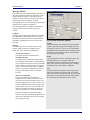
1.1 Overview of Inertial Explorer
Waypoint Products Group’s Inertial Explorer postprocessing software suite integrates rate data from six
degrees of freedom IMU sensor arrays with GNSS
information processed with an integrated GNSS postprocessor (same as GrafNav’s). Inertial Explorer utilizes
strapdown accelerometer (Δν) and angular rate (Δθ)
information to produce high rate coordinate and attitude
information from a wide variety of IMUs.
Inertial Explorer implements either a loose coupling of the
GNSS and inertial data or tightly coupled (TC) processing
that uses GPS carrier phase to limit error during periods
where satellite tracking is limited or variable (even if only
2 or 3 satellites are visible). It is important to time-tag the
inertial measurements to the GPS time frame during the
data collection process. Proper synchronization is vital.
Otherwise, the IMU data will not process. In NovAtel’s
SPAN system, IMU data is automatically synchronized
and the Inertial Explorer’s GNSS decoder automatically
extracts the IMU data.
This manual assumes the use of the GrafNav/
GrafNet 8.10 Manual you can request a copy from
Customer Service or download it from our web
site at www.novatel.com.
How to start Inertial Explorer
1. Verify installation.
2. Click on Inertial Explorer to start the
program.
For NovAtel SPAN, be sure that the Extract
inertial SPAN data option is enabled in the
OEM4 decoding options so that Waypoint’s
generic IMR (raw IMU data) file is created
automatically.
OEMV users can use the OEM4 decoder.
1.2 Getting Started with Inertial
Explorer
This section provides a step-by step procedures on how to
process data in Inertial Explorer.
Installation
Verify that the installation was successful by ensuring that
you have a Waypoint Inertial Explorer program group on
your computer. If this program group is not there, refer to
the GrafNav/GrafNet 8.10 Manual for installation
instructions.
19
Inertial Explorer 8.10 User Guide Rev 5
Chapter 1
Inertial Explorer
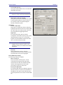
How to convert IMU data
1. Open the conversion utility via File |
Convert | Raw IMU Data to Waypoint
Generic.
2. Click the Browse button to locate the raw
IMU data file.
3. Under the IMU Profiles box, select the
appropriate IMU type.
4. Click Convert to create the IMR file. See
Chapter 2 on Page 49 for help.
5. Add the file to the project via File | Add IMU
File.
How to determine processing time range
1. Select Output | Plot Results.
Convert and Process GNSS Data
Refer to the GrafNav/GrafNet 8.10 Manual to process
GNSS data. The only exception is that the new project
is created in Inertial Explorer, not GrafNav.
Convert IMU Data
IMU data must be converted to Waypoint’s generic
IMR format for processing. To do this, follow the steps
in the shaded box.
NovAtel SPAN users don’t have to follow these
steps because they have a one step process to
convert their IMU data.
Determine Processing Time Range
NovAtel SPAN users do not need this procedure
because the IMU and GNSS logs automatically.
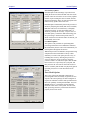
2. Load the File Data Coverage plot.
3. View the time line for GNSS and IMU data
acquisition, and find the time range that has
an overlap.
4. Right-click the desired time and select Set
IMU Processing Time | Start, or End,
depending on the direction being processed.
Before the IMU data can be processed, establish a
processing time range. To do this, find the first and last
epochs of IMU data with concurrent GNSS data.
The IMU sensor might not be configured to start
and stop collecting data at the same time as the
GNSS receivers.
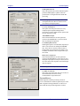
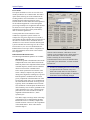
How to process IMU Data
1. From the Process menu, click Process IMU.
2. Double-check the processing time range
under the General tab and the alignment
settings under the Forward and Reverse tabs.
3. Under the GNSS Updates tab. Enter the 3D
lever arm offset from the IMU sensor to the
GPS antenna. If this offset is unknown, then
enable the Solver lever arm values as
additional Kalman filter states option.
Entering the correct value is always preferable to
solving.
4. Select an error profile under the Error Model
tab. From the list that appears, select the one
corresponding to the IMU being used. Click
OK to begin processing.
For users operating in a good GNSS environment,
processing is relatively straightforward provided the
correct IMU Error Model has been chosen.
20
The steps to determine processing time ranges are in
the shaded box.
Determine Alignment Method
Once the GNSS data is processed, use the File Data
Coverage plot in conjunction with the Velocity Profile
plot to decide which alignment mode to use. A static
coarse alignment of two minutes in both directions is
preferred for optimal processing.
If no static data is present at the start and/or end times
of the Velocity Profile plot, then perform kinematic
alignment instead. For static alignment, this plot helps
to determine how much time is available for the
processor to use. The amount of time for the alignment
can be set under the Forward and Reverse tabs via
Process | Process IMU. The correct time length must
be assigned because any movement during the static
alignment results in an error.
Fine static alignment is only practical for high
accuracy IMUs and generally requires at least 10
minutes. Kinematic alignment requires 4-8
seconds.
Inertial Explorer 8.10 User Guide Rev 5
Inertial Explorer
Chapter 1
Process IMU Data
The steps for processing IMU data are in the shaded
box on Page 20.
Plotting and Quality Control
Once processing is complete, view the quality of the
results by analyzing the IMU plots. Under the Output
menu, choose Results to access the following IMU
plots:
Attitude (Roll and Pitch)
This plot shows the roll and pitch profile of the
processed IMU data.
Attitude (Azimuth/Heading)
This plot shows the heading/azimuth of the IMU and
the GNSS course-over-ground. They should be in
reasonable agreement.
If the red line and green line are 180º different, then the
IMU has been mounted backwards, and a rotation of
180º about the Z-axis will need to be entered under the
Advanced tab of the IMU processing options.
Attitude Separation
This plot requires that forward and reverse have both
been processed. It shows the difference between their
attitude values and, ideally, they should agree.
IMU-GNSS Position Misclosure
This plot shows the difference between the GNSS-only
and the GNSS/IMU trajectories and they should agree.
Use Build Custom List to add some of the these
plots to the list.
Export Final Coordinates
The steps for exporting final coordinates are in the
shaded box.
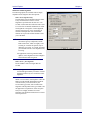
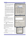
How to export final coordinates
1. Select Output | Export Wizard.
2. Specify the source for the solution.
Epochs outputs the trajectory, while
Features/Stations exports positions only
for loaded features, such as camera
marks.
3. Select a profile. For Inertial Explorer,
select IMU Data as the profile.
4. Click Next.
5. Use the processing datum for the datum
screen.
If prompted for the geoid undulation file, it
can be found on the distribution CD.
Inertial Explorer 8.10 User Guide Rev 5
21
Chapter 1
Inertial Explorer
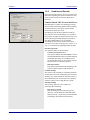
How to start a new project using Auto Start:
File Menu
1. Enter a name for the project with File
Name*. Check that the file path is pointing
to the directory where the project files are
saved.
Refer to the GrafNav/GrafNet 8.10 Manual for
information on the features available via this menu.
The points relevant to Inertial Explorer are discussed in
this section of the manual.
2. Choose the Master Station File(s). This is
the GNSS data file collected at the
reference station.
1.3.1
Raw GNSS data files must first be converted to
Waypoint’s common format (GPB). Refer to
Chapter 8 of the GrafNav/GrafNet Version 8.10
Manual for more information on converting data.
3. Choose the Remote File. It must contain
GNSS data collected during the same time
period as the reference station.
4. Choose a Processing Profile that best suits
the application.When in doubt, choose
either the Factory Defaults or GrafNav
Defaults.
5. Check the Start processing page right away
box, and click OK to process the GNSS
data. Refer to Chapter 2 of the GrafNav/
GrafNet Version 8.10 Manual for more
information on GNSS processing.
6. Select File | Add IMU File.The IMU data
must be concurrent with the master and
base station and remote data. To verify this,
click the Plot Coverage button to display
the File Data Coverage plot.
This step is not necessary if you are auto-starting.
The IMU data must be converted to the IMR format
before being added to the project.
* Choosing a name of an existing project overwrites that
project.
Continued on the next page.
22
1.3
New Project
Auto Start
Auto Start prompts for all the information required to
process IMU data. This option adds reference and
remote stations and allows a project setting that best
suits the application.
To have Auto start begin processing automatically,
activate the Start processing right away box. The Auto
Start steps are in the shaded box.
1.3.2
Add Master File (s)
Entering the proper reference station coordinates is
essential for obtaining high accuracies. The values that
appear are averaged from the GPB file and may have
errors of 10 metres or more. For IGS and CORS
stations, ARP (antenna reference point) coordinates are
pre-loaded in the Favourites Manager. Refer to
Chapter 2 of the GrafNav/GrafNet 8.10 Manual for
more information.
proper datum selection is very important as well.
CORS sites are stored in NAD83 and IGS sites in
WGS84. WGS84 coordinates are different from
NAD83 coordinates by ~2 m, so care should be taken
when using these coordinates.
Be sure to set the ellipsoidal/orthometric height
flag correctly.
1.3.3
Add Remote File
When the adding the remote GNSS data file, enter the
remote station antenna height. If it is not entered, then
the final height coordinates includes the antenna height
and this causes a vertical shift. If only the ellipsoidal or
orthometric height of the antenna is of interest, then
enter zero.
Inertial Explorer 8.10 User Guide Rev 5
Inertial Explorer
1.3.4
Add IMU File
When starting a new project, the program needs the
data collected from the IMU.
The IMU file must be in the IMR format before
being added.
1.3.5
Convert
Raw GNSS to GPB
If data is logged without using Waypoint’s logging
software, it will have to be converted to GPB format
for processing. Refer to Chapter 8 of the GrafNav/
GrafNet Version 8.10 Manual.
Raw IMU Data to Waypoint Generic (IMR)
IMU data must be converted to IMR format in order to
be processed by Inertial Explorer. Use this utility to
perform this conversion. See Section 1.2, on Page 19
for help.
GPB to RINEX
This produces a RINEX file from GPB files and
supports the creation of Version 2.0 and 2.1 of the
RINEX format. For additional information, refer to
Chapter 8 of the GrafNav/GrafNet Version 8.10
Manual.
1.3.6
Chapter 1
How to start a new project using Auto
Start con’t...
7. Choose the DMR file. If any DMI data is
available, select the Enable DMI data
option. This data must be collected
concurrently with the rest of the data in
the project. Use the Plot Coverage button
to find overlapping DMR data.
8. Choose an Error Model. Several error
models are available during GNSS-IMU
processing. For the best results, select the
profile that is most suitable to the IMU
being used.
9. Enter the Master Station Coordinates.
10. Enter the Remote Station Antenna Height
This antenna height applies primarily to
kinematic trajectories. It is overridden by features
(stations/events) and static sessions. To change
the antenna height on static sessions, select View |
Objects | KAR/Static, then select Edit for each
static session.
Removing Processing Files
This removes all the files associated with any given
project. Refer to Chapter 2 of the GrafNav/GrafNet
Version 8.10 Manual for details of this utility. Inertial
Explorer capabilities are discussed here.
Files to Remove
Selects files to remove from the project or folder.
Inertial Processing
Removes all ASCII and binary files created during
IMU processing, including message logs and
trajectories.
Inertial Smoothing
Removes all ASCII and binary files created during
smoothing.
Inertial Explorer 8.10 User Guide Rev 5
23
Chapter 1
Inertial Explorer
1.4
View Menu
Refer to Chapter 2 of the GrafNav/GrafNet Version
8.10 Manual for a description of all the features
available in this menu
In Inertial Explorer, view IMU message log (FIL/
RIL) and trajectory (FIM/RIM/SFIM/SRIM) files,
as well as tightly coupled message log and
trajectory under View | Forward Solution and View
| Reverse Solution. See Section 3.2, on Page 54 for
information on file formats.
1.5
Process Menu
Refer to the GrafNav/GrafNet Version 8.10 Manual for
information regarding all of the features available via
this menu. Only those features that are exclusive to
Inertial Explorer are discussed here.
Processing Directions
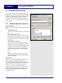
1.5.1
Process IMU (loosely coupled)
Forward
Processes data chronologically, starting from the
beginning and in same direction as it was collected.
This window provides access to most settings related to
loosely coupled IMU processing.
Reverse
Processes data set backwards, meaning it starts at the
end and stops at the beginning.
File/Run Info
The following fields are displayed:
Both
Processes data in both directions sequentially or, for
computers with dual processing capabilities,
simultaneously. Assuming the appropriate option is
enabled, the two solutions are combined.
General
IMU meas file
Displays the path to the binary IMU measurement
file that was added to the project. If incorrect, go
to File | Add IMU File to locate the proper raw
data file.
Process
The following options are available:
Direction to process
Forward and reverse IMU processing is possible
in Inertial Explorer. This option defines in which
direction through time the data is to be processed.
The different processing directions are listed in the
shaded box.
24
Inertial Explorer 8.10 User Guide Rev 5
Inertial Explorer
Chapter 1
Process IMU data only
This option enables/disables the use of GNSS data
during IMU processing.
This mode of processing is not recommended
because it is only used for special applications.
Output binary values for smoother
This option ensures that the FBI/RBI files required
to use the RTS smoother are written to disk. To
save disk space and not run data through the
smoother, disable this option.
Time Range
Process All IMU Data
If this option is enabled, the software obtains the
beginning and end times from the raw binary IMU
file. These times are in GPS seconds of the week
for typical GPS time-tagged applications.
Begin Time
For forward processing, this time should
correspond to a time in the trajectory files created
during GNSS processing. If it is, then Inertial
Explorer uses the GNSS-derived position at that
time to seed the inertial processing.
The time used here is mission-dependent and
should be chosen with care because a poor
alignment results in poor attitude and coordinate
information.
End Time
Same considerations as above. This time
determines the point at which forward processing
stops and when reverse processing begins.
Interval/Data Rate Settings
The following settings are available:
IMU raw data rate
This is the number of IMU epochs / second
collected and time-tagged in the binary IMU
measurement file. This value should be doublechecked. The integration interval for IMU
processing is the inverse of this value.
Extract from IMR header
For uncertain IMU data rates, enable this option to
allow the software to read it in from the header in
the IMR file. This option assumes that the proper
conversion parameters were used to create the IMR
file.
Inertial Explorer 8.10 User Guide Rev 5
25
Chapter 1
Inertial Explorer
GNSS update interval
This value specifies the rate that Inertial Explorer
performs GNSS updates. Updates cannot be
performed at a rate higher than the GNSS data
processing.
Performing updates at a rate higher than 1 Hz is
not helpful unless the data was collected in an
environment with high dynamics.
Use every GNSS epoch
This option forces the processor to use every
computed epoch outputted during GNSS
processing. It sets the update interval equal to that
used for GNSS processing.
ASCII/Kalman output
This field determines the rate that epochs are
written to the FIM/RIM files. Use these ASCII
files for plotting and inspection.
Use GNSS update interval
Enabling this option is recommended, especially if
there is not an interest in reading the FIM/RIM
files. These files are written at epochs where a
GNSS update was performed. If an update is not
available, mechanized values output at the top of
the second.
Binary hi-res output rate
This field determines the rate that epochs are
written to the BIF/BIR files. These files are used
during the output process in Export Wizard, and so
the value entered here depends on the final output
interval required.
Lowering this drastically reduces file sizes.
Use IMU raw data rate
This option forces the binary files to be written at
the mechanization rate and it is only
recommended to output at this rate.
Forward/Reverse
Initial alignment, whether processing forward or
reverse, determines the initial roll, pitch and yaw of the
IMU. Alignment settings should be set with care to
ensure that the best possible alignment is formed.
26
Inertial Explorer 8.10 User Guide Rev 5
Inertial Explorer
Chapter 1
Method for Initial Alignment
The following options are available and are largely
dependent on the length of static data present:
Static coarse alignment only
The data being used for alignment must be static
as any motion results in an error. Coarse
alignment is performed for the first 30 to 120
seconds of static IMU data collection and is used
as a seed value for attitude information for either
fine alignment or navigation. Coarse alignment
uses the sensed gravity vector components to
estimate roll and pitch. It uses sensed Earthrotation rate to provide an initial estimate of the
yaw of the IMU.
Most low accuracy sensors, such as MEMS,
can measure gravity components, but the
Earth-rotation rate, which is roughly 15 arc
seconds per second at the equator, may be
masked by gyro noise. As a result, the initial
yaw estimate from the coarse alignment may
be wrong.
For applications involving constant GNSS
updates, coarse alignment is often enough to
start kinematic IMU navigation.
Static coarse + fine alignment
Invoke if IMU is static for longer than 120
seconds.
Many high precision IMU applications
recommend approximately 2 minutes of coarse
alignment followed by 8 to 10 minutes of fine
alignment.
Within 5 to 10 minutes, GNSS updates enable the
IMU to provide attitude information consistent
with the accuracy level achievable by the
accelerometer/gyro triad, with or without fine
alignment. This depends on the type of IMU, and
the application’s requirements. After roll, pitch
and yaw are roughly estimated for coarse
alignment, fine alignment refines them to a better
level of precision.
Inertial Explorer 8.10 User Guide Rev 5
27
Chapter 1
Inertial Explorer
Transfer alignment
If roll, pitch and yaw are known, these values can
be entered as initial integration constants to allow
navigation to proceed. Attitude angles can be
provided by another IMU, in which case the
misalignment between the IMUs must be applied,
or they can be extracted from another trajectory,
such as the opposite processing direction.
Click Enter / Attitude to scan the first epoch
appearing in the IMU trajectory file of the
direction opposite that of the one being processed.
The attitude and velocities, as well as their
standard deviations are loaded
In-Motion Kinematic Alignment
When neither static data or a priori attitude
information are available, alignment can be done
using vehicle motion. This requires a short period
of time where the vehicle is relatively level and
moving in a relatively straight line followed by
some higher dynamics, such as an aircraft S turn.
The time period can range from 4 to 40 seconds,
depending on the dynamics at the chosen start
time.
This feature is useful in the presence of large data
gaps. While Inertial Explorer has been successful
at aligning tactical grade systems using this
method, there is no guarantee regarding lesser
grade IMUs. It might even be necessary to pick a
different error model in order to prevent
instabilities arising in the Kalman filter.
Initial Static Alignment Period
The length of time assigned to static alignment depends
on the method of alignment being used. In all cases, it
is important that the values entered are in accordance
with the Begin and End times specified under the
General tab.
To perform a static alignment, specify the length of
time that the IMU was stationary. If this is unknown,
the Velocity Profile plot obtained from the GNSS
processing is useful. If selected, the time used for fine
alignment is determined by differencing the Total and
Coarse time fields.
Depending on the data collection methodology, to
perform kinematic alignment, assign roughly 4 to 8
seconds for static alignment.
This field does not apply for transfer alignment or
for in motion alignment.
28
Inertial Explorer 8.10 User Guide Rev 5
Inertial Explorer
Chapter 1
Initial Position and Velocity
There are two options available here:
Determine from GNSS
This method is for collected GNSS data in
addition to IMU data. The starting position and
velocity is read in from the GNSS trajectory
specified under the Source of GNSS Updates box.
Use entered values
This option is for performing IMU-only
processing. If GNSS data has been processed,
load the position from a computed trajectory.
Otherwise, enter it manually. In either case, click
the Enter Position and Velocity button to access
the input window.
Source of GNSS Updates
Use this option to manually select the GNSS trajectory
file from which Inertial Explorer obtains updates. In
most cases, the CMB file is suggested or specify an
alternate file by selecting External trajectory from the
drop-down menu and clicking the Browse External
button. Regardless of which file is selected, doublecheck the File name field to ensure the proper file has
been selected.
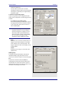
GNSS
Direction of Travel
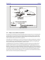
Figure 1: Body Frame Definition for Lever
Arm Offset
The IMU is the local origin of the system, and the
measurements are defined as the following:
X: The measured lateral distance in the vehicle body
frame from the IMU to the GNSS antenna.
Y: The measured distance along the longitudinal axis
of the vehicle from the IMU to the GNSS antenna.
Z: The measured height change from the IMU to the
GNSS antenna.
Lever Arm Offset (IMU ◊ GNSS)
In order for the GNSS updates to be performed
accurately, enter the 3-D offset from the center of the
IMU sensor array to the GNSS antenna.This offset
vector must be entered with respect to the body-frame
of the vehicle, as the image in the shaded box shows.
Save lever arms for future access with the
Favorites button.
Alternatively, if this offset is not precisely known, or
simply not known at all, enable the Solve lever arm
values as additional Kalman filter states option. The
accuracy achieved via this option depends on the type
of IMU used, but is normally better than 20 cm.
GNSS Position Updates
The following settings are available:
Use GNSS position update
This option is strongly recommended because it
ensures the use of GNSS positions for updates
during IMU processing. Without this option
enabled, the IMU trajectory drifts drastically.
Inertial Explorer 8.10 User Guide Rev 5
29
Chapter 1
Inertial Explorer
Require fixed ambiguities
This option forces the processor to only use GNSS
position updates for those epochs where the carrier
phase ambiguities were fixed.
Inertial Explorer uses an internal weighting
scheme to assign weights to GNSS updates based
on their quality. This option should be left
disabled.
Minimum acceptable quality
This setting specifies a criteria which GNSS
epochs must meet in order to be used as updates.
Refer to Chapter 2 of the GrafNav/GrafNet
Version 8.10 Manual for a description of the
quality numbers used for GNSS processing.
StdDev. tolerance
This value determines the maximum allowable
standard deviation of a GNSS position being used
as an update.
Scale variances by
Increases or decreases the variances determined
by GrafNav. This variance information is used by
the IMU filter in Kalman update routines to
weight the GNSS position update. The covariance
information produced by the GNSS filter can be
optimistic, and so this is a simple way of
providing the IMU filter with a more realistic
update variance.
GNSS Velocity Updates
GrafNav uses Doppler information to compute GNSSderived velocities.
Doppler accuracies vary significantly depending
on the receiver. View the L1 Doppler Residual
RMS via Tools | Plot GNSS/IMU Data. The
standard deviation of the Doppler measurements
used by the GNSS Kalman filter can be controlled
via Settings | Individual | Measurements.
Use GNSS velocity update
Enabled by default, but can be disabled to
eliminate the use of GNSS velocity information
for updates.
Doppler meas. tolerance
Only GNSS velocities with RMS residuals less
than this value are used as velocity updates in the
IMU filter.
30
Inertial Explorer 8.10 User Guide Rev 5
Inertial Explorer
Chapter 1
Scale vel. variances by
Used to reduce or increase the covariance
information related to GNSS velocity. By default,
the Doppler is significantly de-weighted during
GNSS processing.
Continuous GNSS Heading Update
Course-over-ground (COG) is computed from the
GNSS velocity components. The following options are
available:
Use GNSS track for heading update
If the forward-pointing axis of the IMU is more or
less aligned in some known orientation with the
Y-axis of the body frame, then use COG as a
direct azimuth update.
Take care when doing so, as it may be difficult
to guarantee that the two axes are aligned.
Aircraft crab angles are examples of errors
which can produce significant differences.
Some low accuracy sensors, such as MEMS,
may not produce meaningful heading
information without enabling this option.
Offset
Permits the entry of a known constant offset, in
degrees, between the forward axis of the IMU
sensor and the Y-axis of the body frame. This
angle is required in order to successfully use the
heading updates.
Std Dev
Estimated error, in degrees, of the offset value
defined above.
DMI Options
To integrate the data from distance measurement
instruments (DMI), engage the Enable distance
measurement (odometer) updates to access the options.
File
Use the Browse button to locate the DMR file
containing the measurements from the DMI. Once a
valid file has been selected, the software scans it to
detect how many sensors were used. Use Info to view
information concerning the selected file.
Inertial Explorer 8.10 User Guide Rev 5
31
Chapter 1
Inertial Explorer
Sensor(s)
Displays the sensors with data that is used during
processing. The number of these entries depends on
how many sensors were detected in the DMR file and
whether or not they were all incorporated. Use the Add
button to include any sensors in the DMR file which
were previously being excluded. Use the Remove
button to eliminate the use of a specific sensor’s data.
Use the edit button to modify the lever arm values
relating the IMU to a specific DMI.
Settings
The following settings pertain to the added DMR file.
DMI observation treatment
A typical DMI will either output a tick count or a
velocity vector.
If tick counts are recorded, Inertial Explorer
converts them into velocity vectors. If velocity
vectors have been recorded, then the software uses
them as such.
Automatically detect ZUPTs from DMI sensor
A DMI can often be used to determine periods of
zero velocity, which can help improve accuracies.
The performance of this feature is dependent on
the type of DMI being used so it is suggested to
process data with and without this option to
determine its usefulness.
Measurement standard deviations
The standard deviation associated with the DMI
measurements depend on the DMI being used. As
such, this value may need to be determined
empirically.
Wheel circumference
The default value is 1.96m. Change this value if it
is not correct. Small errors are compensated for by
the computed scale factor during processing. It is
also possible to allow the software to determine
this value based on the header in the DMR file,
assuming such information is available.
32
Inertial Explorer 8.10 User Guide Rev 5
Inertial Explorer
Chapter 1
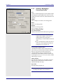
Advanced Options
Sensor Body Rotations
Many typical IMU installations have the surface of the
IMU directly attached to the floor of the vehicle so the
sensor frame of the IMU and the body frame of the
vehicle are more or less aligned. In these installations,
the roll, pitch and yaw of the vehicle are directly sensed
by the IMU. Some IMUs are installed in a tilted
position with respect to the body frame of the vehicle.
If the tilt between the IMU frame and body frame is
known, Inertial Explorer compensates so that the
attitude information produced is with respect to vehicle
body frame, not the IMU sensor frame.
The order of rotations employed is Rx, then Ry,
followed by Rz.
Initial Accel. Biases/ Gyro Drift Values
Inertial sensors tend to contain biases that can be
defined as long-term constants. In cases involving
tactical or navigation grade units, these values have
been calibrated by the manufacturers. Enter these
biases here to allow Inertial Explorer to remove them
from the Δν and Δθ measurements during processing.
This method assumes that the manufacturer has made
these values available to you. Calibrations can be
performed here and used for subsequent missions.
The highest accuracies are achieved for those inertial
units with predictable and known turn-on to turn-on
biases. However, the methods of rigorously calibrating
inertial sensors with off-line procedures involving rate
tables are outside the scope of the Inertial Explorer
software.
Ensure that any values entered here are in the required
units and are with respect to the body frame. See What
is a body frame? on Page 62 for a definition of the
body frame for Inertial Explorer. If the IMU has a
different sensor frame definition (that is, a sensor frame
which is not coincident with the body frame of the
vehicle), ensure that the biases in the pitch axis are
entered in the X-axis fields, with the appropriate sign.
The bias in the roll axis should be entered into the Yaxis fields, and those for the yaw axis should be entered
into the Z-axis fields.
Inertial Explorer does not rely on the presence of this
information, so if these values are not known, then
leave them as zero. In such instances, the calibration of
the sensor is attempted through the alignment
procedure and the ensuing GNSS updates throughout
the mission.
Inertial Explorer 8.10 User Guide Rev 5
33
Chapter 1
Inertial Explorer
Zero Velocity Updates
Inertial Explorer takes advantage of periods of time
during the mission in which the IMU was static. Such
periods of time are referred to as zero velocity updates
(ZUPT). Upon reaching the start of a ZUPT, Inertial
Explorer assumes the data to be static and replaces the
GNSS velocity update values with zeros.
Inertial Explorer automatically detects the presence of
ZUPTs by analyzing the GNSS, IMU and, if available,
DMI data. This is true for both loosely- and tightlycoupled processing. As such, the manual entry of
ZUPTs is generally not necessary, except in cases of
poor data quality. Consult the "IMU Status Flag" plot
after processing to determine the periods where a
ZUPT was detected. If a known ZUPT was missed, you
can manually enter it here.
Coordinate Updates
This option is only available for performing IMU
processing without the aid of GNSS data. Otherwise,
this functionality must be carried out automatically via
GNSS updates throughout the mission.
Without the presence of GNSS data, the positions being
computed from the inertial data are likely to drift
drastically over time. This option provides a way of
bounding these errors by allowing the processor to
correct its trajectory at any given time where the
position is known. As such, this requires that the IMU
have traveled over a previously surveyed point, and
that you know the exact time at which this occurred.
Since it is unlikely that the IMU was physically placed
upon this point, the lever arm offset must also be
entered.
Error Model Options
This is one of the most important components of
processing IMU data successfully. In general, the less
expensive the sensor package, the more tuning that is
required to find initial variances and spectral densities
that work optimally for that particular IMU. For some
MEMS sensors, it is critical that spectral densities
match the sensor noise of the system. In some cases,
IMU processing cannot be performed at all without a
properly chosen error model.
34
Inertial Explorer 8.10 User Guide Rev 5
Inertial Explorer
Chapter 1
Error Model
The options available are to the use one of the error
models provided or use a custom model. The former
option entails selecting one of the models from the
scrolling window, each of which has a set of initial
standard deviation and spectral density values
associated with it. These models have been optimized
for the indicated application or sensor through the
processing of multiple sets of applicable data. Because
all values have been empirically derived through a
trial-and-error process, the accuracy achievable by
their use cannot be guaranteed.
Certain profiles have been tailored for certain
conditions, as opposed to specific sensors. For
example, the Navigation (High Precision) model is
most suitable for high-end units with gyro drift rates on
the order of 0.01º/hr or better, whereas the Tactical
(Medium Precision) model is aimed at medium-grade
systems with drift rates in the range of 1º/hr to 10º/hr.
The Automotive (Low Precision) model allows the
Kalman filter to loosen up in order to compensate for
poor field conditions, such as short or non-existent
static alignment.
Initial Standard Deviation Values
The following mathematical quantities are available:
Misalignment
These terms pertain to the difference between the
computed direction cosine matrix and relate the
IMU body frame to the computation frame (ECEF
in Inertial Explorer), and an error-free idealized
direction cosine matrix or attitude matrix.
These values represent the best estimate of the
sensor’s ability to compute roll, pitch and yaw
during coarse alignment, assuming any is present.
Roll and pitch are estimated from the sensed
gravity components in the horizontal axes of the
accelerometer triad, while yaw is estimated from
the sensed Earth rate about the leveled gyro axes.
Typically, while even MEMS sensors can make
some estimation of roll and pitch, the Earth rate is
often masked by noise for lower-grade IMUs. The
values entered here for x and y, which represent
pitch and roll, are often as much as an order of
magnitude smaller than that for z, which
represents yaw.
How to create a custom profile:
Click the Add From button, which allows for the
creation of a new model based on a default model, or
click the Edit button, which accesses the default
models. Generally, the former method is
recommended, because it allows the default models,
as provided by the manufacturer, to remain available
for future use.
In either case, disabling the Lock selection setting
is required before the selection of any error
model can be made. Once an error model has
been selected, this setting should be re-enabled to
ensure that it is not accidentally changed.
If in doubt, simply enter large values in the range
of thousand of arc seconds and allow the IMU
Kalman filter time to eventually compute more
sensible estimates of the error in the computation
of the attitude matrix. These values must be
entered in degrees.
Inertial Explorer 8.10 User Guide Rev 5
35
Chapter 1
Inertial Explorer
Accel Bias
These values represent the initial uncertainties in
the a priori knowledge of the constant bias errors
in the accelerometer triad. They are in relation to
the accelerometer biases entered under the
Advanced tab. If these bias values were left at
zero, meaning that they are unknown, then the
standard deviation values entered here should
reflect this uncertainty. The processor then
computes the biases on-the-fly. These values
should be entered in m/s2.
Gyro Drift
These values refer to the initial uncertainty
regarding the a priori knowledge of the sensor
drift in the gyroscopes. Again, if the biases under
the Advanced tab were left at zero, then enter
standard deviations values here that reflect this.
The program attempts to compute reasonable
values during processing. All values should be
entered in degrees /sec.
Spectral Densities Values
Generally speaking, the lower the grade of the sensor,
the larger the spectral densities that should be used for
processing. As previously discussed, the spectral
densities add noise to the covariance propagation
process prior to filtering. Therefore, the higher the
densities, the greater the weight that is placed on the
GNSS updates during filtering. The following
mathematical quantities are available:
Misalignment
A misalignment noise density, in arcseconds2/sec,
becomes a covariance when multiplied by some
time interval, δt. If the sensor triad is problematic
in terms of providing an accurate attitude matrix,
or if initial alignment is poor, then you may need
to introduce large spectral density values here.
These spectral components add noise to the
computed Kalman covariances for misalignment,
which, in turn, forces the processor to rely more
heavily on the GNSS position and velocity
updates. As a result, large errors in the direction
cosine matrix are compensated for.
Accel Bias
Accelerometer bias densities, when multiplied by
the prediction time interval, act as additive noise
to the accelerometer bias states. As such, larger
values here may help to compensate for large
biases in the accelerometers.
36
Inertial Explorer 8.10 User Guide Rev 5
Inertial Explorer
Chapter 1
Gyro Drift
Gyroscope drift densities similarly act as additives
to the covariances computed for the gyroscope
drift states. In the case of inexpensive units, larger
values here may be necessary.
Velocity
Velocity spectral densities are noise densities that
account for unmodeled velocity effects during
each Kalman prediction. Increasing this value
permits more emphasis to be placed on the GNSS
update data, but may also lead to an increase in
error growth during outages. For this reason, these
values should be determined as part of the tuning
process. The default values are recommended
unless dealing with a trajectory of unusually high
dynamics, such as a race car, in which case these
may need to be reduced by an order of magnitude.
Position
Position spectral densities are noise densities that
account for unmodeled position effects during
each Kalman prediction. Apply all of the
considerations mentioned above here for the
velocity spectral densities.
User Commands
Certain options available in Inertial Explorer cannot be
accessed through the options menu. A full list of
configured options is available under this tab and may
be invoked to employ special features or overwrite
defaults.
For an explanation of all the commands available here,
see Appendix A, on Page 83.
1.5.2
Process TC (tightly coupled
IMU)
This window provides access to most settings related to
tightly coupled IMU processing. See Section 4.11, on
Page 79 for more information and refer to the
GrafNav/GrafNet Version 8.10 Manual for information
regarding all of the features available via this menu.
Only those features that are exclusive to Inertial
Explorer are discussed here.
Settings
Gives the option of the processing direction.
GNSS Settings
See Section 1.5, on Page 24 for more information.
IMU Settings
See Section 1.5, on Page 24 for more information.
Process Information
Provides run information and user information.
Inertial Explorer 8.10 User Guide Rev 5
37
Chapter 1
Inertial Explorer
1.5.3
Combine and Smooth
Refer to the GrafNav/GrafNet Version 8.10 Manual for
information regarding the options available here. Only
points relevant exclusively to Inertial Explorer are
made here.
Combine/Smooth IMU Forward and Reverse
Inertial Explorer is capable of combining processing
directions and/or performing Kalman filter smoothing
on inertial trajectory. This option requires that the
inertial data is already processed.
Smoothing provides the most significant results on
those data sets where GNSS outages were a problem.
By using this smoother, the position and velocity errors
can be reduced significantly during those periods of
time when GNSS updates were not available.
Smoothing can also clean up position and velocity
accuracies even if there are no gaps. See Chapter 4, on
Page 61 for information regarding the RTS smoother.
Function to perform
Two options available are the following:
Combine forward and reverse
This option combines the FIM and RIM, as well as
the FTM and RTM files that were produced during
GNSS-IMU processing. No smoothing will be
performed. This feature is very useful to compare
forward and reverse attitude trajectories.
Run RTS smoother
This option performs RTS back smoothing on the
loosely coupled or tightly coupled solution.
Combine Settings
This option is only available for combining unfiltered
forward and reverse files. Enabling this option creates a
BIC/BTC file, which contains the inertial trajectory at
the mechanization rate. Use this option for exporting
either the camera events or high data rate epochs.
Smoother Settings
The following options are only available for
performing RTS smoothing:
Direction(s) to smooth
RTS smoothing can be performed in just one
direction, or both. Much like GNSS and GNSSIMU processing, it is generally recommended that
smoothing be performed in both directions.
38
Inertial Explorer 8.10 User Guide Rev 5
Inertial Explorer
Chapter 1
Output files
Use this to change the filename and filepath of the
output files created during smoothing. It is
recommended that they not be changed because it
removes their automatic association to the project.
Chapter 3 on Page 53 provides a description of
the file formats.
Time Range
This setting controls which period of time to perform
the combining and/or smoothing of the trajectories.
Epochs outside of this time range is not considered and
does not appear in the output files.
Combine Any Two Solutions
This option combines any two trajectory files, whether
they be derived from GNSS-only or GNSS-IMU
processing. It provides a means of comparing the
trajectory obtained before and after smoothing.
Inertial Explorer 8.10 User Guide Rev 5
39
Chapter 1
Inertial Explorer
1.5.4 Solve Boresighting Angles
Please see Section 4.4, on Page 69 for a description
and diagram of the navigation values.
Show
This drop-down menu is linked to the window below
it and gives viewing access to the values listed in the
shaded box.
Settings
The following features are available:
Values that are visible with the Show drop
down menu:
Navigation values
The roll, pitch, and heading values, along with their
associated standard deviations, is displayed for each
loaded camera event. The coordinates of the IMU at the
time of the event is also displayed. These values are
generally transferred from Inertial Explorer directly and
correspond to the IMU values interpolated at camera
event times.
Photo E/O values
The omega, phi, and kappa values, along with their
associated standard deviations, are displayed for each
loaded camera event. These values are produced
externally in a photogrammetric package.
Matches/residuals
Before the computations begin, choose whether or not to
include the observations associated with a camera event
in the least squares procedure by simply right-clicking
on the event. Once the least squares procedure has
finished, the window is updated with the final residual
values at each camera event. Additional information,
such as quality indicators and computed omega, phi, and
kappa values are also displayed.
40
Calibration name
Enter a name to distinguish calibration runs from
one another. Inertial Explorer keeps a history of
calibration runs, so a unique identifier is helpful
when trying to recover previous results. This is
useful for using multiple systems and/or tracking
stability over time.
Boresight Angles
Upon successful completion of the calibration
procedure, the final values for the computed
boresight angles are displayed here.
Add results to list
When this option is enabled, the last values
computed by the program are stored so that they
are easily accessible by the Export Wizard.
View report after computation
Enabling this option forces the software to launch
the boresighting report upon successful
completion of a calibration. The contents of the
report are discussed later on.
Auto-update navigation angles on entry
When this option is enabled, Inertial Explorer
loads the latest navigation values for the camera
events into the boresighting module.
Inertial Explorer 8.10 User Guide Rev 5
Inertial Explorer
Chapter 1
Message Window
This window provides valuable insight on the status of
the current calibration. Whenever input data is being
loaded, read the messages to ensure the expected
number of camera events have been read in. Once the
calibration procedure is complete, the final
boresighting values, as well as the number of iterations
needed to arrive at them, are displayed.
The following options are available via the buttons
along the bottom of the Solve Boresight Angles
window:
Compute
Assuming all the required input data has been loaded,
press this button to begin the iterative least squares
procedure. The Message Window contains pertinent
information regarding the success or failure of the
procedure.
Settings…
This button gives access to the Boresight Settings
window, which is useful for configuring many
parameters used in the boresight calibration.
Axes/System Definition
The options are listed in the shaded box.
Grid/Map Definition
The options made available here depend on the
system definition chosen above. If the input angle
were provided with respect to a map grid, then the
selection made here determines the convergence
value, α, used to form the Rg matrix. In addition,
grid users are given the opportunity to enter the
average ground height in order to maximize
accuracy.
Measurement Weighting
The selections made here determine the
composition of the variance-covariance matrix
used in the least squares procedure to derive the
final boresighting values. Choose to enter a set of
constant standard deviation values to apply to all
measurements, or have the values derived from
either the navigation SD values, the photo SD
values (if provided), or a combination of both.
Axes/System Definition options
System
The selection made here defines the ground coordinate
system to which the omega, phi, and kappa values are
oriented see Section 4.4, on Page 69 for a description
and diagram of the navigation values. Normally, they are
referenced to a map projection, which is defined in the
Grid/Map Definition settings.
Order
This setting defines the order in which the omega, phi,
and kappa angles are to be applied during the
transformation from the ground system to the image or
IMU system. Only the omega-primary, phi-secondary,
and kappa-tertiary rotation order is supported.
Axes
Use this to define the orientation of the image system.
The most commonly used system is the conventional
frame, where the x-axis points forward, the y-axis points
left, and the z-axis points upwards. The frame defined
here determines the composition of the Rc matrix.
The other setting here pertains to the outlier
tolerance. The value specified here determines at
which point a measurement is removed from the
least squares procedure.
Inertial Explorer 8.10 User Guide Rev 5
41
Chapter 1
Inertial Explorer
Display Units
These options pertain to the values displayed in
the Solve Boresight Angle window and determine
which units are used when writing to the Boresight
Report file. These options also allow the number
of decimals places to which all values are
displayed or written to be modified.
New
This button clears any stored data from previous
calibration runs in order to start a new one.
Load
Use this to load the required navigation and exterior
orientation input data.
The navigation data can be obtained either by loading
the latest set of roll, pitch, and heading values
computed by Inertial Explorer, or by an external file
which contains this information for each camera event.
Alternatively, if such information is available, there is
the ability to provide the module directly with the
omega, phi, and kappa angles required to rotate the
ground system into the IMU frame. Obtaining the
attitude angles directly from Inertial Explorer is by far
the most common usage.
The exterior orientation parameters for each photo must
be supplied by an external file. This file should contain
the omega, phi, and kappa angles required to rotate the
ground system into the image system.
View
This button gives access to the post-calibration report.
The report contains relevant boresight calibration
information, as well as a list of all the input data
provided for each camera event. The bottom of the
report displays the boresight values and residuals from
the final iteration.
This report can be viewed through either NotePad
or the internal Inertial Explorer ASCII viewer.
This button also gives you access to the calibration
history. For each calibration run, the final
boresighting results have been saved, assuming the
Add results to list option is enabled.
Clear Msg
This button simply clears the Message Window of any
messages currently displayed.
42
Inertial Explorer 8.10 User Guide Rev 5
Inertial Explorer
1.5.5
Chapter 1
Loading IMU Solutions
This feature loads of the project’s IMU solution files.
Choosing to load the forward IMU solution file (FIM)
or the reverse solution file (RIM) loads the solutions
most recently processed in the respective direction. The
combined IMU solution file (CIM) only exists if you
have combined your FIM and RIM files.
Loading Smoothed IMU Solutions
This feature is virtually identical to that described
above, but it loads the most-recently smoothed IMU
trajectory files. The files available for loading depend
on the directions in which smoothing has been
performed. See Chapter 4.3.6 on Page 68 for help
using the RTS smoother.
Input Formats
The boresighting module supports input from external
data files so ensure compatibility before attempting to
use any of these files. The list of fields supported for
input is provided under the File formats drop-down
menu of the given import window.
All fields must be space-delimited and appear in the
same order as that specified by the File format
selection made under the drop-down menu. If there are
column headers in the input file, they are skipped.
Ensure that the proper units are specified under the
Attitude units drop-down menu.
The IDs used in the input file must match those
used in Inertial Explorer in order for the
boresighting module to correctly relate
corresponding data.
Any XYZ coordinates imported for the photos
are not used by the module. The formats
which include these variables are only
supported to facilitate the import process if
you do not wish to go through the trouble of
removing those fields from your input files
beforehand.
Inertial Explorer 8.10 User Guide Rev 5
43
Chapter 1
Inertial Explorer
1.6 Settings Menu
Table 1: IMU Plots
Plot
Description
Accelerometer
Bias
This is the apparent output in acceleration when there is no
input acceleration present. It is computed by the GNSS/INS
Kalman filter and the effects may be sinusoidal or random. It
is plotted in terms of the X (right direction), Y (forward
direction), and Z (up direction) of the INS body. Generally,
they should stabilize after the alignment period and agree
when processed in both directions.
Attitude
(Azimuth/
Heading)
Plots the heading and GNSS COG (course-over-ground)
that was computed from the GNSS/INS processing. Effects
of crabbing is visible in this plot if the GNSS COG bears a
constant offset from INS heading. The IMU Heading COG
Difference plot shows the difference between these two
heading values. Note that any transitions between a heading
of 359 degrees and 0 degrees shows up as a vertical line.
Attitude
(Roll and Pitch)
Plots the roll and pitch values from GNSS/INS processing.
In airborne data, it is common to see roll values between 30
degrees and pitch values of around 10 degrees, depending
on the flight pattern of the aircraft itself.
Attitude
Separation
This plot shows the difference between the forward and
reverse solutions in terms of roll, pitch, and heading. A zero
separation is ideal, as it indicates matching solutions in the
forward and reverse IMU processing. Spikes at the
beginning and the end of the plot are common, as they
indicate the periods of alignment.
DMI Scale
Factor
This plot presents the DMI scale factor, as computed by the
Kalman filter. It should be loaded separately for forward and
reverse processing to ensure that the same scale factor is
computed in both directions. Ideally, the plotted line should
be horizontal, indicating a constant scale factor.
DMI Residual
This plot presents the difference between the computed
displacement or velocity and that reported by the DMI.
Estimated
Accelerometer
Bias Accuracy
This shows the estimated standard deviation of the
accelerometer bias. It is plotted in terms of the X (right
direction), Y (forward direction), and Z (up direction) of the
INS body.
Estimated
Attitude
Accuracy
This plot shows the standard deviation computed in the
GNSS/INS Kalman filter in terms of roll, pitch, and heading.
Estimated Gyro
Drift Accuracy
This plot shows the estimated standard deviation of the gyro
drift rate, which generally decreases with time. It is plotted in
terms of the X (right direction), Y (forward direction), and Z
(up direction) of the INS body.
Gyro Drift Rate
This is the apparent change in angular rate over a period of
time, as computed by the GNSS/INS Kalman filter. The
effects are usually random. It is plotted in terms of the X
(right direction), Y (forward direction), and Z (up direction) of
the INS body. Generally, they should stabilize after the
alignment period and agree when processed in both
directions.
Gyro Attitude
Misclosure
This plots shows the misclosure (residual) of gyroscope
Kalman filter updates. Large values here could be an
indication of attitude instability.
IMU Angular
Rates
This plot shows the gyroscope rate of change of attitude in
the X, Y, and Z axes of the IMU body with the drift removed.
This plot is used to check the gyros.
Refer to Chapter 2 of the GrafNav/
GrafNet Version 8.10 Manual for
information regarding all of the
features available via this menu. Only
those features exclusive to Inertial
Explorer are discussed here.
1.6.1 IMU Settings
This option provides access to the
IMU processing settings without
starting processing. Data processing
can only be engaged via the OK
button under Process | Process IMU.
See Section 1.5, on Page 24 for a
complete description of all the
settings available here.
1.7 Output Menu
Refer to Chapter 2 of the GrafNav/
GrafNet Version 8.10 Manual for
information regarding all of the
features available via this menu. Only
those features exclusive to Inertial
Explorer are discussed here.
1.7.1 Plot Results
Refer to Chapter 2 of the GrafNav/
GrafNet Version 8.10 Manual for
information regarding all of the
GNSS plots available here.
Table 1, in the shaded box on this
page and the following page, contains
a description of the IMU plots
available only through Inertial
Explorer.
Continued on the next page.
44
Inertial Explorer 8.10 User Guide Rev 5
Inertial Explorer
1.7.2
Export Wizard
Only the Export Wizard window exclusive to Inertial
Explorer is discussed here. Refer to the GrafNav/
GrafNet Version 8.10 Manual for additional
information concerning this feature.
Chapter 1
Table 1:IMU Plots con’t...
Plot
Description
IMU Status
Flag
Shows the status of IMU processing. Specifically,
this plot provides indication of the type of update, if
any, being applied at each epoch.
IMU-GPS
Lever Arm
This plots presents the body-frame components of
the lever arm offset between the IMU and GNSS
antenna. If the offset was manually entered, then
this plot bears constant horizontal lines. If left to be
solved by the Kalman filter, this plot shows the
computed values.
IMU
Heading
COG
difference
This plot is the difference between the IMU heading
and the GNSS course-over-ground values. Effects
of crabbing shows up as a direct bias in this plot.
Velocity
Separation
Plots the difference between the East, North and
Up components of velocity computed during
forward and reverse processing. Requires that both
directions be processed and combined.
IMU-GPS
Position
Misclosure
This plot shows the difference between the GNSS
solution and the mechanized INS positions
obtained from the GNSS/INS processing. This is a
good analysis tool used to check the GNSS/INS
solution as well as checking INS stability. Large
jumps or spikes may indicate a bad INS solution,
whereas separations nearing zero confirms the
GPS solution.
IMU-GPS
Velocity
Misclosure
This plot shows the difference between the GNSS
calculated velocity and the mechanized INS
velocity obtained from the GNSS/INS processing.
Another good analysis tool used to check INS
stability.
IMU
Heading
COG
difference
This plot is the difference between the IMU heading
and the GNSS course-over-ground values. Effects
of crabbing shows up as a direct bias in this plot.
IMU Epoch Settings
Epoch/Output Interval
The Kalman/GPS interval indicates the interval used
during GPS processing, while the IMU integration
interval displays the interval at which the IMU data
was processed. These values can only be changed
prior to processing. The Output data interval defines
the interval to export solutions. The output interval
can be set as high as 1000 Hz, regardless of what
interval the data was processed at.
The time range for which to obtain outputs
can also be limited here.
Lever Arm/ Offset
Allows for the coordinates of the IMU, calculated
via the IMU Kalman filter, to be transferred to an
alternate sensor’s location.
The orientation of the frame in which these
coordinates must be entered. You are also
free to save your offset for future use via the
Favorites button.
1.8 Tools Menu
Refer to Chapter 2 of the GrafNav/GrafNet Version
8.10 Manual for information regarding all of the
options available via this menu.
Inertial Explorer 8.10 User Guide Rev 5
45
Chapter 1
Inertial Explorer
1.9
Interactive Windows
Refer to the GrafNav/GrafNet Version 8.10 Manual for
information regarding the Map Window and the
features available within it. Only the additional
information available through Inertial Explorer
regarding the Processing Window are discussed here.
1.10 Processing Window
Table 1 on Page 44 , contains a list of the additional
parameters available for viewing in Inertial Explorer
during processing. Display these values via the View
button in the Processing Window.
The values in the GrafNav/GrafNet Version 8.10
Manual differs in the manners in which they are
computed depending on the mode of processing being
performed.
If the GNSS is being processed, then the values
displayed are those computed in the Kalman filter.
However, during the IMU processing, the values
displayed reflect those calculated in the IMU Kalman
filter, using the GNSS information as updates. Ideally,
these values should agree. When they do not, monitor
the position and velocity misclosure.
1.11 Help Menu
1.11.1 Help Topics
Opens an HTML version of this manual, with the
GrafNav portion included. This feature is a quick and
easily accessible reference.
1.11.2 The Waypoint Products
Group’s Web Page
This option opens a web browser to the Waypoint
Products Group’s page on NovAtel’s website, where
details on the latest versions, patches, information on
GNSS/INS, and technical reports can be found.
46
Inertial Explorer 8.10 User Guide Rev 5
Inertial Explorer
1.11.3 About Inertial Explorer
This window displays information about the software
version, build dates, copyright information, hardware
lock key information, and DLL information.
Access the hardware key utility from this window by
clicking Key Util (Upgrade). This tool is useful for
upgrades. The Dependent Files window displays a list
of executables and DLLs associated with Inertial
Explorer. The date and time of the files are shown, as
well as a quick description of the file.
Chapter 1
Manufacturer files available to download
from Waypoint’s FTP site
manufact.adf
List of antenna profiles. Refer to the GrafNav/
GrafNet Version 8.10 Manual for more details.
manufact.dn1
List of base stations available for the Download
utility. This is usually updated monthly.
Click Download latest manufacturer files to connect to
Waypoint’s FTP site (Internet connection required) to
download the files listed in the shaded box.
manufact.dtm
List of datums, ellipsoids, and transformations
between datums. Refer to Chapter 11 of the GrafNav/
GrafNet Version 8.10 Manual for details.
Most of these manufact files have an associated user
file, where personal information is saved. These files
are not modified when you download the latest
manufacturer files. It is important, for this reason, to
not modify the manufact files, as they are overwritten
when this option is used.
manufact.fvt
List of Favourites and the groups they are contained
in. These only contain coordinates for stations
available with the Download utility. Refer to the
GrafNav/GrafNet Version 8.10 Manual for more
information.
manufact.grd
List that contains available grids such as UTM, US
State Plane, Gauss Kruger etc.. Refer to the GrafNav/
GrafNet Version 8.10 Manual for more details.
manufact.svi
A file that associates a PRN number with a satellite
type (Block II, Block IIA etc.) for purposes of
determining the center of mass of the satellite. It
assists in single point processing. This file should not
be modified.
manufact.cim
Provides a set of default conversion parameters for
various IMU raw data formats. This file is accessed
during the conversion from raw data to IMR format.
See Chapter 2 on Page 49 for details.
manufact.imu
Contains the error profile parameters for various types
of IMUs. The values associated with each model have
been empirically derived by the Waypoint Products
Group staff based solely on the data sets they have
encountered.
manufact.dcb
List of the differential code biases, in nanoseconds,
between the P1 and C/A code for each satellite. Used
by PPP.
Inertial Explorer 8.10 User Guide Rev 5
47
Chapter 1
48
Inertial Explorer
Inertial Explorer 8.10 User Guide Rev 5
Chapter 2
Conversion Utilities
2.1 Raw IMU Data Converter
The IMU Data Converter utility is a Win32 application
program that converts custom data formats into a generic
raw IMU data format, which is described in Section 3.2.1,
on Page 54 of this manual. This utility is available
exclusively to users of Inertial Explorer and may be
accessed via File | Convert | Raw IMU Data to Waypoint
Generic (IMR).
2.1.1
Waypoint IMU Data Conversion
Input/Output Files
Refers to the names and locations of all input and output
files.
Input Binary IMU File
Click the Browse button to locate the raw IMU data
file.
Output Waypoint Binary File
By default, the binary output file created are given
the same filename as the input file, but with an IMR
extension. It will be saved to the directory containing
the input file.
Output Waypoint ASCII File
If the Output ASCII option is enabled, the utility
generates an ASCII file containing the GPS time, as
well as the gyroscope and acceleration measurements
of all three axes for the first thousand epochs. Use
this to detect any errors that may occur during the
conversion, such as the use of an incorrect scale
factor.
Path
Displays the path to the directory containing the
input file. All output files created by this utility are
saved to the directory.
IMU Profiles
Displays a scroll-down list of profiles available for use
during conversion. Each profile contains a set of
conversion parameters designed to decode measurement
data files produced by the indicated sensor. Choose one
profile from the list, or, if necessary, create one. See
Section 2.1.1, on Page 49 for help. Once all the
appropriate fields have been entered, click the Convert
button to start converting IMU data into IMR format. A
message window appears to show the status of the
conversion process.
49
Inertial Explorer 8.10 User Guide Rev 5
Chapter 2
Conversion Utilities
2.1.2
Creating / Modifying a
Conversion Profile
New
Creates a customized profile to convert unique format
into Waypoint’s generic IMR format. This is used for
custom scale factors, data rates, and orientations in raw
data files.
Modify
Allows changes to be made to an existing profile.
Delete
Deletes an existing profile.
Rename
Renames an existing profile.
Sensor/Timing Settings
Gyro Measurements
Pertains to the measurements made by the gyroscopes.
The inverse value of the scale factor is
required. For example, a scale factor of
0.0004, which can be represented
fractionally by 1/2500, should be entered as
2500.
The gyro measurements can take the form of
delta theta, where angular increments are
being observed, or angular rate.
Accelerometers Measurements
Considerations similar to those made for the scale
factor of the gyro measurements should be made here.
That is to say, the inverse of the scale factor is
required. Much like the gyro measurements, the
accelerometer measurements can take two forms, the
first being data velocity, or velocity increments, and the
other being acceleration.
Timing Settings
Enter the data collection rate of the IMU sensor here
and specify any offset that may exist between the
GNSS and the IMU time tags.
Byte Order
This flag must be properly set.
If the proper byte order is not specified, the
decoding of the binary raw file will fail.
50
Inertial Explorer 8.10 User Guide Rev 5
Conversion Utilities
Chapter 2
Time Tag Format
There are only two options available here as the data is
either acquired in the GPS time frame or the UTC time
frame. This must be correctly identified in order for the
IMU data to be properly aligned with the GNSS data.
Time Tag Source
Specify here whether the time tags represent the GPS
Corrected Time or the GPS Received Time.
2.1.3
Sensor Orientation Settings
Defined the orientation of the IMU here using the steps
in the shaded box.
The orientation will always be right-handed.
2.1.4
Decoder Settings
Specifies which library will be used to perform the
conversion, based on the input format of the raw data
file. For most sensors, this should be left untouched.
For SPAN, the IMU decoding is handled
through the GNSS decoder.
How to define the orientation of the IMU:
1. Specify the X-direction by selecting the
direction that corresponds to the X-axis of
the sensor frame.
2. Click Select to set that direction to the Xaxis.
3. Specify the Y-direction next by selecting
the direction that corresponds to the Y-axis
of the sensor frame.
4. Click Select to set that direction to the Yaxis.
Given the constraint that the frame is right-handed,
this direction will be automatically determined by
the software.
5. Click Update to apply the new sensor
orientation to the profile.
If a mistake is made at any point during the process,
click Clear to start over.
6. Click OK to save the new profile.
It should immediately appear in the scroll-down list
under the IMU Profiles box of the main window.
Inertial Explorer 8.10 User Guide Rev 5
51
Chapter 2
52
Conversion Utilities
Inertial Explorer 8.10 User Guide Rev 5
Chapter 3
3.1
Data and File Formats
Data Formats
In theory, virtually any IMU sensor can be used with
Inertial Explorer. The only requirement is that the data
be logged in the format provided below, which allows
easy decoding with IMU Data Conversion utility
described in Section 2.1.1, on Page 49 .
The Table 2, in the shaded box, presents the binary
structure in which the conversion utility expects the
raw IMU data to be logged.
Please contact Customer Service if you are
unable to log data into the specified format.
3.1.1
NovAtel’s SPAN Technology
With the use of NovAtel’s SPAN technology, note the
difference in the IMU data decoding procedure. Since
the raw IMU data measurements are embedded into
the same binary file containing the raw GNSS
measurements, only one step will be needed to
separate the data and convert it into the Waypoint
Group’s format so the Raw IMU Data Converter
utility does not need to be used.
Table 2: Binary Structure of Raw Data
Size
(bytes)
Word
Type
Description
GpsTime
8
real
time of the current IMU rate
measurements in GPS
seconds of the week.
GyroX
4
long
scaled X-body axis gyro
measurement as anangular
increment or angular rate
GyroY
4
long
scaled Y-body axis gyro
measurement as anangular
increment or angular rate
GyroZ
4
long
scaled Z-body axis gyro
measurement as anangular
increment or angular rate
AccelX
4
long
scaled X-body axis accel
measurement as a velocity
increment or acceleration
AccelY
4
long
scaled Y-body axis accel
measurement as a velocity
increment or acceleration
AccelZ
4
long
scaled Z-body axis accel
measurement as a velocity
increment or acceleration
Instead, decode the GNSS and IMU data
simultaneously via the Convert Raw GNSS data to
GPB utility, which can be accessed via File | Convert.
When adding the measurement file to the Convert
Files window for decoding, ensure that the drop-down
menu under the Receiver Type box has been set to
NovAtel OEM4. Then, click either the Global Options
or Options button to gain access to the IMU decoding
settings.
AG11 = AG58
AG17 = AG62
53
Inertial Explorer 8.10 User Guide Rev 5
Chapter 3
3.2
Data and File Formats
File Formats
3.2.1
IMR File
Waypoint converts all custom IMU raw binary formats into a generic format (IMR), which is read from Inertial
Explorer following the decoding process in IMU Data Converter. See Chapter 2 on Page 49 for more details.
Because it contains vital information for reading and decoding the data, the first 512 bytes of the generic IMU data
format is a header which must be filled in, read and interpreted. In a C/C++ structure definition, the generic format
header has the following fields:
typedef struct
{
char szHeader[8];
char bIsIntelOrMotorola;
double dVersionNumber;
int bDeltaTheta;
int bDeltaVelocity;
double dDataRateHz;
double dGyroScaleFactor;
double dAccelScaleFactor;
// $IMURAW[0] ◊ NULL terminated ACII string
// 0 - Intel (little Endian) - default
// 1 - Motorola (big Endian) - swap bytes for IExplorer
// This can be set for any user who directly writes in our format
// with a Big Endian processor. IExplorer will swap the bytes
// i.e 2.00
// Default is 1, which indicates the data to follow will be delta
// thetas, meaning angular increments. i.e. scale and divide by
// fDataRateHz to get degrees/second. If the flag is set to 0, then
// the data will be read directly as scaled angular rates
// Default is 1, which indicates the data to follow be delta ν’s,
// meaning velocity increments. i.e. scale and divide by
// fDataRateHz to get m/s2. If the flag is set to 0, then the data will
// be read directly as scaled accelerations
// i.e. 100.0 records / second; If you do not know it, set this to
// zero and then fill it in from the interface dialogue boxes
// Scale (multiply) the gyro measurements by this to get degrees, if
// iDeltasOrRates=0. Scale the gyros by this to get degrees/sec, if
// iDeltasOrRates=1. If you do not know it, then the data can not
// be processed. Our default is to store the gyro data in 0.01 arcsec
// increments or 0.01 arcsec/sec, so that GYRO_SCALE = 360000.
// Scale (multiply) the accel measurements by this to get m/s, if
// iDeltasOrRates=0. Scale the accels by this to get m/s/s, if
// iDeltasOrRates=1. If you do not know it, the data can not be
// processed. Our default is to store the accel data in 1e-6 m/s
// increments or 1e-6 m/s/s, so that ACCEL_SCALE = 1000000
// defines in INSDLL.DLL
54
// IMU_TIMEFRAME_GPS
0 ◊ raw data file uses GPS seconds of week
// IMU_TIMEFRAME_UTC
1 ◊ raw data file uses UTC - convert to GPS
int iUtcOrGpsTime;
// Defines time-tags as being in UTC or GPS seconds of week
// 0 – unknown (default is GPS), 1 – UTC, 2 – GPS
Inertial Explorer 8.10 User Guide Rev 5
Data and File Formats
Chapter 3
// defines in INSDLL.DLL
// IMU_GPS_TIME_FRAME
0 ◊ GPS timetags are corr_time
// IMU_RCVR_TIME_FRAME
1 ◊ GPS time-tags are rcv_time
int iRcvTimeOrCorrTime;
// defines whether the GPS time-tags are in the nominal top of the
// second or are corrected for receiver time bias
// 0 – do not know (our default is corrected time)
// 1 – receive time on the nominal top of the epoch
// 2 – corrected time ie corr_time = rcv_time - rcvr_clock_bias
double dTimeTagBias;
// default is 0.0, but if you have a known millisec level bias in your
// GPS◊INS time tags, enter it here
char Reserved[447]
}
// space reserved for future use; these bytes should be zeroed
ImuGenericHeaderType;
The single header, which is a total of 512 bytes long, is followed by a structure of the following type for each
IMU measurement epoch:
typedef struct
{
double Time;
long gx,gy,gz;
long ax,ay,az;
// GPS time frame – seconds of the week
// delta theta or angular rate depending on flag in the header
// delta ν or acceleration depending on flag in the header
} INS_type;
// this is the binary structure type expected in GPSIMU
The angular increments (or angular rates) are scaled long integers. The scale factor to obtain a double
precision word must be supplied in the header. Similarly, the accelerations (or velocity increments) are
signed four byte words and must be scaled by a double precision variable given in the header.
Inertial Explorer 8.10 User Guide Rev 5
55
Chapter 3
Data and File Formats
3.3 Output Files
FIL/RIL/FTL/RTL message files:
Coarse Alignment Succeeded on attempt #1
This message appears at the beginning of forward/
reverse processing. It indicates that the coarse
alignment was successful.
Reading GrafNav Record: 1000
Scanning the GPS/IMU data before
processing.
Warning: Coarse Alignment has used up all
of the Align Time. Will Continue
Processing anyway...
This section discusses the different output files that are
created when processing with Inertial Explorer.
3.3.1 FIL/RIL/FTL/RTL Files
Message Log files echo all error and warning messages
sent to the Process Window during INS processing.
Some example messages are in the shaded box.
This message indicates that the INS processor used all
the coarse alignment time entered.
Warning - GUPT Missing in GPS data ->
DT: 0.200
This message indicates the presence of a gap in GPS
data of time DT seconds. As a result, the processor
cannot use this time as a GPS update.
Warning: Trace of Body-Earth matrix < 0
after update
Check on Fix: 1-tr{C} of transform matrix
(0.056389)
This message is purely a mathematical computation
warning.
56
Inertial Explorer 8.10 User Guide Rev 5
Data and File Formats
3.3.2
Chapter 3
FIM/RIM/FTM/RTM Files
This is the output format common to other Waypoint output files.
The first line of the output file always begins with $OUTREC, and is followed by the version number, the processing
engine, and the type of output. An example is given below as the first line:
$OUTREC Ver7.50.2531 INSDLL Forward InsOutput
The output format is the following:
Out {
Tim: InsGpsTime InsCorrTime GpsWeek#
GPS seconds of week
Geo: latitude longitude_ins ht_ins
DMS, DMS, m
Loc: d_east d_north d_ht vel_east vel_north vel_up m, m, m, m/s, m/s, m/s
Var: Cee Cnn Cup Cve Cvn Cvup TraceCpos
m2, m2/s2
Att: Roll Pitch Azimuth RollSD PitchSD AzimuthSD All values in meters
Drf: GyroX GyroY GyroZ GX_sd GY_sd GZ_sd
All values in degrees/sec
Bia: AccelX AccelY AccelZ AX_sd AY_sd AZ_sd
All values in m/s2
Ecf: ECEF_X ECEF_Y ECEF_Z
All values in meters
Kal: MisalignX MisalignY MisalignZ dX dY dZ dVx dVy dVz
Arcsec, m, m/s
Mis: GPS-IMU_e GPS_IMU_n GPS-IMU_u GPS-IMU_vn GPS-IMU_vn GPS-IMU_vu
GPS-IMU position & velocity misclosures
Accelerations in m/s2
Angular rates in degrees/sec
(C)oarseAlign, Fine (A)lign, (N)avigation,
(U)pdate; 1-AlignMode, 2-VelocityUpdate,
3-GPSUpdate, 4-CoordinateUpdate,
6-Predicted, 7-Interpolated
Flg: S/K NsGps NsGln F/L IonoMode S/D
[S]tatic, [K]inematic; number of GPS sats;
number of GLONASS sats; [F]ixed,
F[L]oat; 0-Off, 1-IonoFree,
2-RelativeModel; [S]ingle, [D]ual
Sta: GPS+IMU_QualityNum GPS_amb_drift GPS_dd_dop pdop hdop vdop
1 - 6, cycles/sec, DOPs
Rms: L1_phase ca_range p1_range L1_doppler
RMS from GPS; m, m, m, m/s
Acc: AccelEast AccelNorth AccelUp
Ang: RollRate PitchRate YawRate
Fli: C/A/N/U 1/2/3../7
}
A numerical example is also given:
Out { Tim: 242454.000 242454.000000 1326
Geo: 38 58 32.81833 -90 01 56.81759 447.3102 0.000
Loc: 27954.263 25107.254 419.862 -37.048 -64.995 1.432
Var: 4.45898e-004 7.89335e-004 1.63980e-003 1.97879e-004 2.37932e-004 2.62523e-004
2.87503e-003
Att: -21.4595 2.8034 203.8579 1.05545e-002 1.12253e-002 2.25285e-002
Drf: 5.10860e-005 -6.59158e-005 -1.76638e-004 8.14676e-005 8.67355e-005 6.86044e-05
Bia: 1.52573e-003 -9.69194e-004 1.84882e-003 6.70535e-004 7.98037e-004 4.89097e-04
Ecf: 27963.018 15450.018 19782.767
Kal: 0.0 -0.4 -0.4 -0.002 0.000 0.000 -0.001 0.000 0.000
Mis: -0.003 0.001 -0.001 0.000 0.000 0.000 209.687 170.538
Acc: 2.633 -0.852 -0.692
Inertial Explorer 8.10 User Guide Rev 5
57
Chapter 3
Data and File Formats
Ang: 1.2924 2.6196 3.8727
Fli: U 3
Flg: K F 9 0
Rms: 0.0280 0.750 0.000 0.089
Sta: 1 0.000600 1.25 1.35 0.94 0.96
}
3.3.3
BIF/BIR/BTF/BTR Files
The data structure used for these binary files appears below:
typedef struct
{
double phi,lamda;
float ht;
} plh_type;
// holds latitude, longitude and height
// degrees
// metres
typedef struct
{
double x,y,z;
} xyz_type;
typedef struct
{
float x,y,z;
} fxyz_type;
typedef struct
{
}
signed long iRoll, iPitch, iYaw;
iatt_type
typedef struct
{
char Str[16];
long HdrSize;
long IsExtended;
long RecSize;
long Reserved1;
double Interval;
char ProgramName[32];
char VersionName[32];
char Direction[16];
char Reserved2[392];
}
// $IMUOUT (see IMU_HDR_STR above)
// size of this header
// true if exended format used (use later)
// size of this record
// for later, zero
// data interval (s)
// program name that created this file
// version that produced file
// “Forward", "Reverse" or "Combined"
// reserved for additional information (zero at creation of new file)
imu_hdr_type;
// normal record definition
typedef struct
58
// sf=1.0e-6
// 80? bytes
Inertial Explorer 8.10 User Guide Rev 5
Data and File Formats
Chapter 3
{
}
double GpsTime;
short WeekNum;
short Reserved;
// GpsTime of this record (0-604800)
// week number
// reserved for future flags
plh_type GeoPos;
fxyz_type LLVel;
// geographic position of this record (deg/m)
// local level velocity (m/s)
fxyz_type LLAcc;
// local level acceleration (m/s2)
iatt_type LLAtt;
fxyz_type LLAttDot;
// local level attitude (deg) (scaled)
// body frame rotational rate (deg/s)
float fPosTrace;
float fVelTrace;
float fAttTrace;
// trace of position covariance (m)
// trace of velocity covariance (m/s)
// trace of attitude covariance (deg)
imu_outrec_type;
Inertial Explorer 8.10 User Guide Rev 5
59
Chapter 3
60
Data and File Formats
Inertial Explorer 8.10 User Guide Rev 5
Chapter 4
FAQ and Tips
4.1 Overview of FAQ and Tips
The following sections offer suggestions on how to
get started, process and analyse GNSS/IMU data in
Inertial Explorer. Here you will find tips regarding
common problems such as data decoding, error
modelling, alignment, processing and analysing
results.
4.2 How are Inertial Explorer
and coordinate frames
related?
Inertial navigation is mainly concerned with
coordinate frames. Inertial sensors measure the rate
information relative to an inertial frame of reference.
An inertial coordinate frame does not rotate or
accelerate with respect a to space-fixed system of
reference. Accelerometers measure change of
velocity with respect to an inertial frame, while
gyroscopes measure change of rotation with respect
to inertial space and they are referred to as inertial
sensors. If measurements made in this inertial frame
can be related to some chosen navigation frame, then
inertial sensors can be used to realize both 3-D
coordinates (X, Y, Z) and 3-D attitude (roll, pitch and
yaw) in a manner that makes sense to navigators.
Figure 2 illustrates the relationship between the
coordinate frames used by Inertial Explorer.
Figure 2: Coordinate Frames in Inertial Explorer1
The inertial (i), computation (e), navigation (l), and
body (b) frames are all portrayed here. Keep Figure 2
in mind during the following discussion.
4.2.1
What is an inertial frame?
A practical implementation of an inertial reference
frame (I-frame) is to define the centre of mass of the
Earth as the origin. The Z-axis of this system goes
through the poles and is coincident with the spin axis
of the Earth. The X-axis is tied to an astronomical
system and points at the vernal equinox, which is
defined as being the point where the apparent Sun
crosses the celestial equator in the spring. The Y-axis
completes a right-hand triad. This system is often
referred to in literature as the Right Ascension system.
It is assumed that a system tied to the stars does not
move for the duration of a typical survey.
1.
61
Dr. El-Sheimy, University of Calgary
Inertial Explorer 8.10 User Guide Rev 5
Chapter 4
FAQ and Tips
4.2.2
Z
Yaw
Roll
Y
Pitch
X
Figure 3: Body Frame Definition
The body frame definition of the measurement unit
may very likely be different from that shown
above. A simple reflection of your body axes into
the body axes given by Inertial Explorer is
typically all that is required to process data.
What is a computation frame?
The frame in which Inertial Explorer performs its
GNSS and inertial computations is the Earth-Centred
Earth-Fixed (ECEF) frame. The origin of this system is
located at the centre of mass of the Earth, a point which
is well-defined by observing the orbits of satellites
together with gravity measurements. The Z-axis is
coincident with the spin axis of the Earth, and is
therefore co-incident with the Z-axis of the I-frame.
The X-axis of the ECEF system points through the
Greenwich Meridian, while the Y-axis completes a
right-hand orthogonal frame. The ECEF frame differs
from an inertial earth-centred frame only by the amount
the earth rotates.
4.2.3
What is a navigation frame?
The purpose of a navigation frame is to allow the ease
visualization of the navigation of the vehicle. Inertial
Explorer employs the Local Level frame, because it is
an appropriate reference system in which coordinates
and attitude information can be output in an intuitive
manner. This system provides coordinates in terms of
East, North, and Up, or, if preferred, in latitude,
longitude, and height. Attitude information is presented
in terms of roll, pitch, and yaw, which reflect the
vehicle’s heading. The origin of this system is defined
as the centre of the sensor array. The Z-axis is
orthogonal to the reference ellipsoid at the sensor array,
while the Y-axis points North and the X-axis points
East.
When making computations in the Local Level frame,
instabilities can arise near the poles due to convergence
of the meridians.
This is not a problem in the case of Inertial
Explorer because it performs its calculations in the
ECEF frame instead.
4.2.4
What is a body frame?
This frame is aligned with respect to the vehicle’s body.
In this discussion, it is assumed that the accelerometer
and gyro measurements are made in the body frame of
the vehicle. This called a strapdown approach to inertial
navigation. The orientation of a vehicle’s body frame is
completely arbitrary from one epoch to the next. One of
the principal challenges in any inertial survey is to
properly compute the orientation of the b-frame with
respect to a chosen computation frame at each and
every measurement epoch. For instance, body to
l-frame angles are roll, pitch and yaw.
62
Inertial Explorer 8.10 User Guide Rev 5
FAQ and Tips
Chapter 4
The B-frame chosen for Inertial Explorer is depicted
in Figure 3. The Y-axis of the body frame is coincident with the longitudinal axis of the vehicle. Its
positive direction points out the nose of the vehicle.
The Y-axis may also be said to define the roll axis of
the vehicle, where positive roll being counterclockwise in a right hand system. The positive Xaxis of the B-frame points out the right side of the
vehicle when one is standing in the vehicle and
facing the positive Y-direction. It contains the
vehicle pitch rate. The positive Z-axis of the body
frame points up, through the roof of the vehicle. A
yaw rate is said to be positive if it is measured
counter-clockwise about the Z-axis.
4.3 What should I know about
inertial processing?
To process measurements made in an inertial frame,
the body frame needs to be re-oriented in such a way
as to make it coincident with the computation frame
or, eventually, the navigation frame, if they are
different. In other words, body frame measurements
should be sensed directly in the desired computation
frame. Furthermore, only those components, which
are due to motion of the vehicle, are of interest.
Hence, gravity, Earth rotation and the curved shape
of the Earth as sensed by the gyroscopes and
accelerometers must be eliminated to ensure that any
sensed accelerations come only from vehicle
dynamics. For example, in the computation frame, if
accelerations along the north-pointing axis are
integrated twice, there is a direct difference in
northing from some known starting location.
Similarly, differences in easting and height can be
obtained by integrating twice along the other two
accelerometer axes, provided these are properly
oriented. If the initial coordinates at the centre of the
sensor array are known at the start of a mission, the
coordinate differences can be used to compute
latitude, longitude, and height for every epoch in the
trajectory.
Inertial Explorer 8.10 User Guide Rev 5
63
Chapter 4
FAQ and Tips
The problem lies in the fact that sensor biases,
measurement noise, errors in initial conditions, and
gravity modeling errors are all integrated along with the
measurements. In terms of attitude, the single
integration results in the platform becoming misaligned
with the computational system. In terms of position,
this misalignment causes the gravity vector to enter
horizontal axes, while the double integration of these
errors leads to an additional quadratic error. The end
result is that significant errors can be quickly realized.
The rotation matrix required to take body-sensed
measurements and place them in the computation frame
at any given epoch is referred to here as the attitude
matrix. The gyro triad is utilized to sense the change in
vehicle rotation from the body frame orientation at one
epoch to the subsequent body frame orientation at the
next epoch. The direction cosine matrix which is
defined in Inertial Explorer to go from body frame to
navigation frame is a function of three consecutive
rotations in yaw, pitch, and roll. The implemented
computation frame is ECEF, so the attitude matrix must
be further rotated as function of latitude and longitude.
Changes in orientation (i.e. angular rates) must be
integrated once in order to obtain angles. This implies
two things, the first being that it is a requirement to
solve for three initial constants for the integration
process to be complete. Secondly, as with the
accelerometers, errors are integrated along with the
measurements. The integration process can then
quickly accumulate errors from the gyroscopes.
64
Inertial Explorer 8.10 User Guide Rev 5
FAQ and Tips
Chapter 4
Figure 4: IMU Camera
4.3.1
Why are error models so important?
Error models are more important for inertial processing than GNSS processing. The term error model in the context
of Inertial Explorer refers to the initial variances and a priori spectral noise densities required by the IMU Kalman
filter. These values are provided via the Error Model tab of the IMU processing settings, where a number of error
models appropriate to specific classes of IMUs are available for selection. You can also build custom error models
suitable to particular inertial measurement units or applications.
Unlike GNSS, inertial computations are very sensitive to the input a priori stochastic information that is available for
each inertial system. As a rule of thumb, the more expensive the IMU, the less likelihood of achieving poor results
from a non-optimal choice of input statistical quantities. A poor choice of noise densities for a navigation grade
inertial system may simply provide a sub-optimal set of outputs for attitude.
An inappropriate choice of noise densities for a MEMS array with a drift of 300º/hour may mean that nonsense is
obtained for attitude information. The process of choosing an appropriate variances and spectral densities for a
particular system is referred to as tuning. Unfortunately, tuning often tends be a somewhat arbitrary process. You
might have to simply guess at the approximate magnitude of the noise densities which help describe the behavior of
an inexpensive inertial system. This can be a tedious and, occasionally, unrewarding process. The creation and tuning
of error models for various classes of IMUs is an on-going task at NovAtel’s Waypoint Products Group. The latest
error models are included in a file called manufact.imu, which can be found in the software installation directory.
Waypoint Products Group is attempting to update this file on a regular basis as more information about the different
sensors on the market is obtained, especially in the MEMS category.
Inertial Explorer 8.10 User Guide Rev 5
65
Chapter 4
FAQ and Tips
4.3.2
Why is alignment so
important?
Alignment is the process of computing the initial values
of roll, pitch, and yaw. proper alignment is very
important to IMU performance and processing because
errors result directly into attitude errors, which can take
some time to correct by the Kalman filter. Alignment
can either be static or kinematic, although the former is
recommended.
Static alignment generally takes place in two stages,
with the first being coarse alignment and the second
being fine alignment. Coarse alignment is a
requirement for static alignment, whereas fine
alignment is optional. If the you have GNSS data
immediately available for updates, the static fine
alignment process can often be ignored.
4.3.3
What is static alignment?
Coarse alignment generally requires 1 to 2 minutes of
static data. The default time for coarse alignment in
Inertial Explorer is 120 seconds. The software monitors
the data and warns you if kinematic data is detected.
During coarse alignment, the basic signal from a set of
static accelerometers is the gravity vector. In this Bframe definition, roll is a function of acceleration as
measured in the X-axis of the body. Pitch is a function
of sensed acceleration in the body’s Y-axis. The
approximate roll and pitch values computed from these
measurements be used to define an approximately level
plane. Initial heading still needs to be computed, and
this is where inexpensive IMU sensors tend to suffer.
Gravity provides a strong signal, and it can be sensed
adequately by even MEMS grade accelerometers.
Heading, or yaw, must be computed by examining the
output of the gyroscopes for Earth rate. For instance, for
an ideal stable platform system, the assumption is that
one horizontal axis points due East. A gyroscope
aligned along this axis is in a no-torque situation
relative to the Earth rotation. Hence, there is no output.
On the other hand, the North-pointing axis senses the
entire Earth rate at that latitude. Consider the magnitude
of the Earth rotation rate at about 15º/ hour. MEMS
rotation sensors can have drifts in the order of 100º/
hour to 300º/hour, and the you can see that the
computation of heading during coarse alignment with
such sensors is impossible. In fact, any output from
such a gyroscope during static alignment can be simply
considered to be noise, meaning that it can be modeled
as a bias. Systems drifting at about 1º/hour should be
able to gyrocompass to some degree of accuracy.
Systems above this may require external aiding for
azimuth determination.
66
Inertial Explorer 8.10 User Guide Rev 5
FAQ and Tips
Chapter 4
Fine alignment is the process of using static data in the
Kalman filter process to fine tune the initial roll, pitch
and yaw computations. If GNSS updates are
immediately available following coarse alignment,
many applications can choose to fine tune the attitude
information from the GNSS information available
during navigation. For instance, an airplane that taxies
down a runway may have sufficient time and update
information to adequately perform a dynamic fine
alignment. By the time the aircraft reaches the area
where the mission takes place, the attitude matrix and
associated sensor biases may be optimized as well as
possible without static fine alignment.
For low grade IMUs, the GNSS update process
can also provide some approximation of
heading during navigation. This works best in
minimal crab environments.
4.3.4
What is kinematic alignment?
It is also possible to transfer initial roll, pitch and yaw
from another sensor while in kinematic mode. Moving
coarse alignments are even possible from only GNSS
update information. Be aware that the process of
alignment is similar to the convergence process which
must be undertaken for computation of GNSS integer
phase ambiguities. Unless using a very expensive IMU,
do not expect to obtain optimal values for attitude until
some static and kinematic data collection has taken
place. This is in the order of minutes, not seconds.
Analogous to GNSS, kinematic IMU alignments take
longer than static alignments. The first 5 to 10 minutes
of any given mission should concern itself with static
and kinematic alignment.
4.3.5
What is IMU Kalman filtering?
The IMU Kalman filter consists of three misalignment
states, three position states, three velocity states, three
gyro bias states, and three accelerometer bias states.
The first nine states are in the ECEF computation
frame. They represent estimated errors in the realization
of an ECEF computation frame from measurements
made in the arbitrary vehicle body frame. The sensor
biases are lumped states accounting for constant and
time-dependent gyroscope and accelerometer
measurement errors. This filter runs in conjunction with
equations which mechanize the IMU rate data, meaning
they propagate the attitude matrix and integrate
coordinate differences between GNSS updates.
Inertial Explorer 8.10 User Guide Rev 5
67
Chapter 4
FAQ and Tips
Table 3: Pitch and Yaw Differences
Attribute
Roll, pitch, yaw
Omega, phi kappa
Order of angles
Yaw, pitch, roll
Omega, phi, kappa
Direction of
rotation
Air-to-ground
Ground-to-air
Ground
coordinate
system
Geographic
(local level)
Normally a grid but may
also be geographic
Direction of
rotation
Air-to-ground
Ground-to-air
For loosely coupled, GNSS data must be processed
first. This produces FWD and REV files, as well as a
CMB file, which represents the weighted mean of the
forward and reverse GNSS processes. Inertial Explorer
reads the CMB file by default and stores the
coordinate, velocity, and associated covariance
information in a binary image in memory. Generally,
IMU measurements and GNSS epochs are not aligned.
Therefore, Inertial Explorer interpolates the inertial
records either side of the GrafNav time-tag to line up a
derived inertial measurement with the corresponding
GPS time. At this derived point, the mechanized
inertial coordinates and velocities are differenced from
the GNSS-computed quantities to obtain the error in
the inertial information. These estimated errors are
used as update information in the IMU Kalman filter.
The covariance information from the GrafNav file is
used as weighting in this update procedure.
Section 1.5.1, on Page 24 discusses the GPS tab
and provides the opportunity to reject GrafNav
information which is deemed unacceptable for
updating purposes. Rejection tolerances can be
based on ambiguity determination, standard
deviation, or quality number. Tolerances are based
on the stand-alone navigation capabilities of the
inertial system. Covariance can also be scaled.
4.3.6
What is Kalman filter
smoothing?
Inertial Explorer offers the opportunity to perform
Kalman filter smoothing on their GNSS/IMU data.
While this feature is aimed primarily at datasets
suffering from GNSS outages, it can be used in
virtually any circumstance where position errors are
large. Without GNSS updates, the Kalman filter is
forced to work in prediction mode, which generally
causes the position errors to grow exponentially.
However, significant positioning errors can also occur
from the presence of poor-quality GNSS data.
The smoothing algorithm implemented was derived by
H. Rauch, K. Tung, and C. Striebel, and, hence, is
often referred to as the RTS smoother. This smoothing
process works backwards, which therefore implies that
data must exist at the epoch after the one being
smoothed. The RTS algorithm employs a fixed interval
technique, meaning that the entire data set is smoothed
at the same, specified interval.
68
Inertial Explorer 8.10 User Guide Rev 5
FAQ and Tips
Chapter 4
As previously mentioned, this backwards smoothing
procedure can be very advantageous for those data
sets where the GNSS data is missing. The algorithm
uses the data from the last epoch and works
backwards to compute new states for each epoch. As
such, an improvement in the results is especially
noticeable if a good solution is available immediately
following an outage. The maximum magnitude of the
position error during a GNSS data gap can be greatly
reduced by applying this RTS smoother.
This new feature only smooths positions and
velocities, not attitude. See Section 1.5.3, on
Page 38 for help using the RTS smoother.
4.4 What do I need to know
about Boresighting?
4.4.1
Why is boresighting needed?
Generally, the IMU and imaging system can never be
perfectly aligned. No matter how perfect the
mechanical installation is, there will most likely be
small angular errors that persist between the systems.
For an object in the image, this error can be quite
significant when projected onto the ground. For the
case of a frame imager, this angular difference can
easily be solved for using photogrammetric means.
4.4.2
How does the boresighting
module work?
The module that comes with Inertial Explorer uses a
"simple" boresighting procedure that utilizes the
omega, phi and kappa angles computed by some
external bundle adjustment package. It then computes
the differences between them and internally
generated values from the IMU processing.
4.4.3
What are omega, phi and
kappa?
Omega, phi and kappa are Euler angles that represent
the angular difference between the imaging and the
ground coordinate systems. The differences between
roll, pitch, and yaw (-ve heading) and omega, phi and
kappa are explained in Table 3 on Page 68 , in the
shaded box.
Inertial Explorer 8.10 User Guide Rev 5
69
Chapter 4
FAQ and Tips
What you need to get started with the
module:
•
4.4.4
Can I use this module to
boresight my pushbroom or
laser data?
A data set flown over a targeted
calibration field with 4 flight lines in
opposing directions (e.g. north, south,
east and west) and 4 to 6 photos in each
line
No, this module only works with frame imagery.
Imagery must have 60% overlap along
each line (stereo photography is highly
desirable) and a minimum of 20% side
lap between lines.
No, you must use an external package to determine the
omega phi and kappa angles for each image.
•
The imagery must have tie points and a
minimum of four control points, although
more can be very helpful
What you need to utilize this module is listed in the
shaded box.
•
Scale is not so important but should
match typical flying scales. Very large
scales (<1:8000) may result in less
accurate boresighting angles due to
increased influence by GNSS positioning
errors.
•
•
GNSS and IMU data that contains
camera event marks. Images must have
been properly time tagged by GNSSIMU system
•
A GNSS-only processed solution initially
•
A valid bundle adjustment solution using
these tie and control points as well as the
GNSS/camera centre positions. Although
using the GNSSposition is not necessary,
it is highly suggested to decorrelate the
image position and attitude.
•
Exported omega, phi, kappa in a format
compatible with this module.
4.4.5
4.4.6
4.4.7
Does this module come with a
bundle adjustment?
What do I need to get started?
What if my photo angles are
not omega primary, phi
secondary and kappa tertiary?
Currently, this module only supports omega primary
angles.
4.4.8
Where is my boresighting file
data stored?
Everything related to the boresighting module is stored
in a BSI file. This file is ASCII but should not need to
be modified.
4.4.9
What if Inertial Explorer does
not support my grid system?
If you are using a grid system not supported by Inertial
Explorer, then convert the roll, pitch and heading
values used to omega, phi and kappa using the
formulation described in Section 4.2, How are Inertial
Explorer and coordinate frames related?.
The naming convention used for the photo IDs
must match that used in Inertial Explorer.
•
70
A fully processed Inertial Explorer
project with a forward, reverse, combined
or smoothed IMU solution loaded.
Inertial Explorer 8.10 User Guide Rev 5
FAQ and Tips
Chapter 4
4.4.10 What mathematical
equations are used by
boresighting?
Equation 1:
⎡X g − X o ⎤
⎡x − xp ⎤
⎢ y − y ⎥ = k ⋅ R cam ⋅ ⎢ Y − Y ⎥
p
o ⎥
ωφκ
⎢ g
⎢
cam⎥
imu
Rωφκ
= ΔRωφκ ⋅ Rωφκ
⎢
⎥
⎢⎣ − f ⎥⎦
⎣ Z g − Zo ⎦
The following is meant to provide information
regarding the equations used by the boresighting
module. The photogrammetric equation is
typically presented as Equation 1, in the box.
The boresighting feature solves for a rotation
cam
Rωφκ
matrix,
required in the derivation of the
which represents the attitude of the image
coordinate system with respect to the ground
coordinate system. This matrix is defined through
Equation 2, in the box.
Where: x, y
xp, yp
f
k
Xg, Yg, Zg
Xo, Yo, Zo
Inertial Explorer’s boresighting module provides
the rotation angles that form the
ΔRωφκ
matrix.
image coordinates
principal point offset
focal length
scale factor
ground coordinates
perspective centre
coordinates
Equation 2:
cam
imu
Rωφκ
= ΔRωφκ ⋅ Rωφκ
Rωφκ
imu
, is computed
The other rotation matrix,
from Equation 3, in the box. In this equation, Rc
accounts for the different axes definition between
the camera and the IMU. In general, when a
conventional image frame is employed, the Rc is
computed by Equation 4, in the box.
Equation 3:
imu
T
Rωφκ
= Rc ⋅ Rrpy
⋅ Rg
Equation 4:
The quantity Rg corrects for the map convergence
and is computed by Equation 5, in the box.
α
Where, difference between grid north and true
north (see convergence angle in Section 1.7.2, on
Page 45 ).
The final quantity required to solve for
imu
Rωφκ
is
Rrpy
, which represents the rotation required to
orientate the IMU into the ground coordinate
system and is computed by Equation 6, in the box.
It is also useful to present the matrix required to
rotate a ground coordinate system into an alternate
coordinate system. This matrix is defined through
Equation 7, in the box.
Rc = R
Equation 5:
0,0,
π
(ω = 0, φ = 0, κ = π / 2)
2
⎡ cos α
R g = ⎢− sin α
⎢
⎢⎣ 0
sin α
cos α
0
0⎤
0⎥
⎥
1⎥⎦
Equation 6:
⎡cos y cos r − sin y sin p sin r
Rrpy = ⎢sin y cos r + cos y sin p sin r
⎢
− cos p sin r
⎣⎢
Where:
r
p
y
− sin y cos p cos y sin r + sin y sin p cos r ⎤
cos y cos p sin y sin r − cos y sin p cos r ⎥
⎥
⎥⎦
sin p
cos p cos r
roll angle
pitch angle
yaw angle
yaw = –heading
Equation 7:
⎡ cos φ cos κ
Rωφκ = ⎢⎢− cos φ sin κ
⎣⎢ sin φ
Inertial Explorer 8.10 User Guide Rev 5
cos ω sin κ + sin ω sin φ cos κ
cos ω cos κ − sin ω sin φ sin κ
− sin ω cos φ
sin ω sin κ − cos ω sin φ cos κ ⎤
sin ω cos κ + cos ω sin φ sin κ ⎥⎥
cos ω cos φ
⎦⎥
71
Chapter 4
FAQ and Tips
4.5 How do I decode raw
inertial data?
The raw IMU data decoder expects binary data in the
format described in Section 2.1.4, on Page 51 . The
decoder needs to read an ASCII profile that defines
which right-hand sensor system the binary data has
been stored in. For example, a given IMU might define
a positive X-axis as pointing out the front of the IMU
box and a positive Z-axis as pointing downwards. The
profile therefore must specify this in order to rotate the
sensor axes into the Y-forward, Z-up system that is
used by Inertial Explorer. The profile also needs to
store values by which to scale the gyro output into
degrees or degrees / second. The accelerometer data
must be scaled to m/s or m/s2.
4.5.1
How do I deal with offsets
between IMU sensor frame and
vehicle body frame?
If the IMU is typically mounted upside down, you may
wish to define a profile of your own, so that Inertial
Explorer automatically decodes your data in a way that
does not require subsequent rotations to be applied
during processing.
If the manufacturer’s sensor system defines Z-down as
positive, create a profile where Z-up and X-back are
defined as being positive. This produces a system in
which the define lever arms can be defined in the same
manner as described in previous sections, which is to
say that the longitudinal axis of the vehicle body
represents Y-forward and the positive Z-axis of the
vehicle body frame points up.
Make sure the positive sense of the rotation angles
matches the positive sense of the vehicle body
frame.
If the you rely on the Sensor ‡ Body Rotation options
under the Advanced tab of the IMU processing
settings, then a rotation about the Y-axis of 180º is
needed to rotate an upside-down IMU into the Inertial
Explorer vehicle body frame. In such a case, the X and
Z components of the lever arm offsets need to be
entered using signage opposite that of Inertial
Explorer’s positive convention in order to transfer the
IMU data to the GNSS antenna correctly.
72
Inertial Explorer 8.10 User Guide Rev 5
FAQ and Tips
Chapter 4
4.6 How do I deal with an
upside down IMU?
In principle, Inertial Explorer should not have any
problems processing data where the sensor frame of
the IMU is mounted at any odd set of angles with
respect to the vehicle body frame. However, the final
output attitude information is, most likely, be pointing
in the wrong direction. Most IMUs have the sensor
frame inscribed on the IMU box. To obtain an output
of roll, pitch and heading relative to the positive
motion of the vehicle or aircraft, then the IMU sensor
frame must be mounted parallel to the body frame of
the vehicle. Alternatively, a profile which fools the
IMU data converter into thinking the sensor frame
has been mounted parallel to the body frame can be
defined. The final or enter rotation angles into the
Advanced Dialog Box. Otherwise, you will output
azimuth to, for example, the wing tip, not the forward
longitudinal axis of the aircraft. Your roll and pitch
might be mixed up. Plot the vehicle GNSS-derived
Course over Ground vs the azimuth make sure your
inertial-defined heading has the right sense.
Otherwise, Inertial Explorer simply processes your
attitude data as is.
If the IMU is mounted upside down, then you
will likely have to change the signs on their
lever arms when you enter them into Inertial
Explorer. If you are unclear about the effects
of mounting the IMU in a configuration
which is not parallel to the body frame of the
vehicle, attempt to visualize it through a
diagram or else contact the Waypoint
Products Group.
4.7 How do I deal with
unknown lever arm offsets
from a GNSS antenna to an
IMU centre?
It is important that the lever arm between the centre
of the IMU and the GNSS L1 phase centre be
measured correctly in the field. Otherwise, the
attitude information will not be optimal, especially in
heading. This problem is particularly severe during
turns.
Inertial Explorer 8.10 User Guide Rev 5
73
Chapter 4
FAQ and Tips
However, if this information is not available, you can
request that Inertial Explorer estimate the lever arm
during data processing. In such a case, ensure that no
Lever Arm Offset values are entered under the GPS tab
of the IMU processing settings, and that the Solver
lever arm values as additional kalman filter states
option is enabled.
In all likelihood, the initial computed estimates are
only accurate to the nearest 30 cm or 40 cm. However,
you can refer to the FIM and RIM files for the lever
arm estimates, under the Lev: field, and enter them
back into the GPS tab dialog box under Lever Arms in
a second iteration. The processor now has better initial
approximates to work with instead of just 0.0’s. Iterate
and re-process until you have lever arm values which
do not change significantly. These might be good to 10
cm or so.
After obtaining the best lever arms possible, you can
run the smoother and output your coordinate and
attitude values. DO NOT SOLVE the lever arms on the
final processing run! Fix them as you obtained them.
Otherwise the final coordinates vary as the lever arms
vary.
4.8
How important is error
model tuning?
Choosing a correct Error Model for the type of IMU
utilized is critical. The Kalman filter can not and will
not operate effectively unless the A priori Error Model
agrees with the specifications given for the initial
standard deviations and especially the spectral noise
densities for the given type of gyros and
accelerometers. Even within IMU types, for example,
1 degree / hour tactical grade systems, Error Models
can differ and must be optimized to provide expected
performance. Additionally, Error Models are not
guaranteed to be optimal for missions outside normal
dynamic ranges. Examples include rocket tests or race
car dynamics. Typical dynamics include van surveys
or airborne photogrammetric surveys. In general, the
Error Models supplied should not have to be modified
by the typical user for their dynamic environment.
The Error Models are stored in ASCII profiles. There
are also Error Models supplied by the Waypoint
Group. See the file called MANUFACT.IMU. This file
should not be modified. Instead, add your own profiles
to the user file.
74
Inertial Explorer 8.10 User Guide Rev 5
FAQ and Tips
4.8.1
How do I build my own error
model?
This is not recommended for our typical user group.
Unless you have special equipment such as rate tables
designed to provide exact motion and dynamics,
please realize that building an Error Model is a best
guess, iterative procedure. You can do it, but it is not
an exact science by any means.
First of all, based on the specifications of your gyros
and accels, try filling in reasonable standard deviation
values for the initial estimates of the misalignments,
accel bias and gyro drifts. These should be loose
enough to allow the Kalman filter to move around
until it can find a steady state but tight enough that
the filter does not diverge. Values here do not have to
be too exact. Typically make them somewhat larger
than the manufacturers specifications and allow the
filter to converge from there.
Spectral densities are a much less exact science. The
manufacturer should provide you with some ideas of
the random noise on the gyros and accels. These can
be entered as starting points. If the densities are too
large, the filter pays little attention to the IMU
measurements and rely on the GNSS/ZUPT/DMI
updates for all of its information content. If the
densities are too tight, the update information is
largely ignored.
Alternately to using information from manufacturer
spec sheets, you may wish to copy a profile from the
manufact file and modify it to your own designs.
4.8.2
How do I know if my error
model is working?
There are three main tests to determine if an Error
Model is optimized for a given IMU or even for a
special dynamic environment. After processing a
reasonable data set, without too much bad data or any
bad data, plot the list in the shaded box from the Plot
Menu.
Inertial Explorer 8.10 User Guide Rev 5
Chapter 4
Plots to test if an Error Model is optimized for
a given IMU
1. IMU-GNSS position misclosure: This value
represents the difference in the stand-alone
IMU solution since the last GNSS update
against the current GNSS solution. If the
GNSS coordinates are good, the error plotted
is due to the performance of the inertial
mechanization equations over the last n
seconds. Clearly, if you have metres of error
over one second, then you have a poorly
determined Error Model.
2. Forward / Reverse Attitude Separation
Plot: This is the most important graph to
examine in the course of model determination.
Experience has shown that the forward /
reverse attitude separation, when optimized is
roughly twice the reasonable expected error
from your system. So if a spectral density is
changed and the attitude separation worsens,
you know that you have gone in the wrong
direction and so on.
3. Gyro Drift and Accel Bias Plots: First, load
the forward or reverse but not combined IMU
solution. Simply put, the gyro drift and accel
biases should appear to be horizontal lines
(more or less) across the plot. They should
look like biases not ramps or random noise.
Ideally, the magnitude of these plots agree
with the manufacturers specs on drift and bias.
Some of the judgements made on the quality of the
graphs described above will come from the
experience. It is difficult to provide absolute numbers
at this point as IMUs differ by orders of magnitude
depending on their manufacture.
75
Chapter 4
FAQ and Tips
4.9 How can I use the
alignment of the IMU?
It is important to choose a start and end time to begin
IMU processing for both forward and reverse
procedures. IMUs need to obtain initial values for the
integration of gyro rate measurements to rotations and
accelerations to coordinate differences. The alignment
period allows you to compute initial approximates for
roll, pitch and yaw. Initial coordinates may be entered
or simply read from the GNSS processed data files.
Ideally, you need STATIC data for the alignment
procedure at both the beginning and end of the GNSS/
INS mission.
4.9.1
How much static alignment
data do I need?
In general, for GNSS/INS processing you only need 12 minutes of static coarse alignment data at the
beginning and end of each data set. In a non-ideal
situation, Inertial Explorer can handle as little as 4
seconds of static data for coarse alignment. Fine
Alignment is an option but not really a requirement if
good GNSS data is available when the vehicle starts to
move.
4.9.2
How do I find start/end times
for the IMU alignment?
Prior to GNSS processing, under the Plot tool select
"File Data Coverage". This plot shows the overlapping
data between GNSS base, GNSS rover and IMU data
files. This plot provides you with an idea of when to
possibly start and end the IMU processing. The
following two questions may remain:
1. Are the start and end times in a static period?
2. How long do these static periods last?
If the GNSS data has been processed, load the GNSS
forward, reverse or combined solution and plot the
GNSS-derived velocity. Again the times are on the
X-axis of the plot. This Velocity plot can be used in
conjunction with the File Data Coverage plot to
provide a good A priori idea of start/end time for
alignment and the number of seconds of alignment in
both forward and reverse directions.
76
Inertial Explorer 8.10 User Guide Rev 5
FAQ and Tips
4.9.3
Chapter 4
How can I use kinematic
alignment?
If no static alignment data is available or you must
re-align due to a inertial data gap, then alignment
while moving is possible and under good conditions
can produce acceptable results. It is important to
examine the velocity plot, if possible, to choose a
section of the vehicle motion which is straight and
level. All that is required is 4 seconds of straight,
level flight or motion for kinematic alignment to
achieve its purpose. If the section of data chosen does
not work, choose another section until the desired
results are achieved.
4.9.4
How can I use transfer
alignment?
Transfer alignment requires that a forward or reverse
IMU file is present containing pre-determined
coordinate, attitude and covariance information.
Alternately, this information can be entered for a
particular time. Transfer alignment should be chosen
at the present time as a last resort.
4.10 Processing Tips
For users operating in a good GNSS environment,
processing should be relatively straightforward
provided the correct IMU Error Model has been
chosen. Nevertheless, there are some input options
which may be considered if the initial data processing
has appeared to have quality problems.
4.10.1 What tolerances should be
used for GNSS updates to the
IMU?
The IMU processing utilizes GNSS information from
the trajectory files in the update process. Under the
default options, GNSS coordinate updates are only
allowed if the standard deviation of the GNSS
coordinates is 2 m at any Q number. In less than ideal
conditions, this may occasionally allow a very poor
GNSS coordinate to be accepted. If there are
unexplained jumps in the IMU position for example,
lower the 2 m tolerance to say 0.5 m and perhaps
even make the Q number smaller. This prevents one
or two bad GNSS updates from contaminating a
significant portion of the survey.
Inertial Explorer 8.10 User Guide Rev 5
77
Chapter 4
FAQ and Tips
4.10.2 How do I use ZUPTs?
Inertial Explorer automatically detects the presence of
ZUPTs by analyzing the GNSS, IMU and, if available,
DMI data. This is true for both loosely- and tightlycoupled processing. As such, the manual entry of
ZUPTs is generally not necessary, except in cases of
poor data quality. Consult the "IMU Status Flag" plot
after processing to determine the periods where a
ZUPT was detected. If a known ZUPT was missed,
you can manually enter it using the "Advanced Tab".
4.10.3 When should I use GNSS
velocity and heading updates?
Inertial Explorer uses GNSS velocity updates by
default. In general, GNSS velocity updates do not add
that much information if the coordinate update has
good quality. Heading updates should only be used for
MEMS type sensors which have poor heading
capabilities. You must know the angle between the
forward pointing axis of the IMU sensor block and the
longitudinal axis of the vehicle body frame in order to
relate the heading from the IMU sensor triad with the
direction of the vehicle. Please enter a reasonable
standard deviation for your knowledge of this angle.
4.10.4 I only have a single point
solution (.FSP File), is this
okay?
This is fine, but please make sure that you do not use
GNSS Velocity updates. Turn this option OFF under
the GPS dialog tab.
4.10.5 Does 10 Hz GNSS data help?
In general, we believe, from our experience, that 1 Hz
GNSS data is sufficient even for updating MEMS
IMUs. This is a decision that you can make from your
own experience with their specific application. We
suggest that you process at 10 Hz and then 1 Hz and
make your own judgement. Clearly, processing time is
saved if you can justify the lower update rate.
78
Inertial Explorer 8.10 User Guide Rev 5
FAQ and Tips
Chapter 4
4.10.6 What should I look for while
the IMU data is processing?
Examining the Processing Inertial Display Box is a
useful exercise while the data is processing. Keep an
eye on the GNSS-IMU Misclosure relative to the
velocity. This relates to the difference in the GNSS
update coordinates and the coordinates computed by
the IMU while the IMU was running in stand-alone
mode since the last update. If you know what the
relative misclosure values should look like during a
good mission, you will have an idea while the data is
processing whether outliers exist in the data set.
Advanced users can also view the gyro and accel
biases for unexpected large offsets as the data is being
run. Speed or velocity is also a good value to monitor.
In a worst case scenario, an unusual large speed is a
good first indicator of trouble.
4.11 Tightly Coupled
Processing Tips
4.11.1 What is the difference between
loosely-coupled and tightlycoupled processing?
Loosely-coupled processing refers to the usage of
GNSS-derived information to update the IMU
Kalman filter. Specifically, the IMU processor reads
in the positions, velocities, and their corresponding
variances as output during GNSS processing. The
IMU processor reads this information and uses it to
update the positions, which would otherwise drift due
to the nature of inertial systems. It follows from this
that loosely-coupled processing is two-step system.
Because the GNSS data is used to compute
positions and/or velocities, at least four
satellites are needed.
Tightly-coupled processing, on the other hand, entails
the use of GNSS and IMU data in one Kalman filter.
The primary advantage is that the filter can be
updated using as little as two satellite measurements,
making it the preferred method of processing when
poor GNSS conditions are encountered. The IMU
data is also used to help detect/reject poor GNSS
measurements, while the phase information can still
be used to aid KAR in resolving ambiguities.
Inertial Explorer 8.10 User Guide Rev 5
79
Chapter 4
FAQ and Tips
Table 4: Inertial Explorer Extensions for
Output Files
File Type
Loosely-Coupled
Tightly-Coupled
GNSS Solution
FWD, REV, CMB or
FSP, RSP, CSP
FWD, REV, CMB
GNSS Static
Summary
FSS, RSS
FSS, RSS
GNSS Message
Log
FML, RML
FML, RML
IMU Solution
FIM, RIM, CIM
FTM, RTM, CTM
IMU Solution
(Smoothed)
SFIM, SRIM, SCIM
SFTM, SRTM,
SCTM
IMU Binary File
BIF, BIR, BIC
BTF, BTR, BTC
IMU Binary File
(Smoothed)
SBIF, SBIR, SBIC
SBTF, SBTR,
SBTC
IMU Message Log
FIL, RIL
FTL, RTL
IMU Smoother
Binary File
FBI, RBI
FBT, RBT
4.11.2 How do I engage looselycoupled and/or tightly-coupled
processing in Inertial
Explorer?
Both methods of processing are available in Inertial
Explorer. As with all versions of Inertial Explorer 7.80
or older, loosely-coupled processing is performed in
two stages. First, the GNSS data is processed to
produce a trajectory. This can be done through
differential processing by using Process | Process
GNSS, or through precise point processing by using
Process | Process PPP. Regardless of which method is
used, ensure that you have achieved satisfactory results
before moving on. The next stage is to engage the IMU
processor by going to Process | Process IMU. It is
important to double-check that the combined solution
file, whether it be the CMB file from differential
processing or the CSP file from precise point
processing, is used as the source for position updates.
This can be verified under the Forward and Reverse
tabs, under the Source of GNSS Updates box.
Tightly-coupled processing is performed in one step,
by going to Process | Process TC. The window that
appears gives you access to all of the same GNSS and
IMU processing options that are available during
loosely-coupled processing. Once you have configured
them, click on the Process button to engage tightlycoupled processing.
Both styles of processing can be performed from
within the same project. Refer to the following
question for more information.
4.11.3 How can I differentiate
between the files created by
loosely-coupled and tightlycoupled processing?
Inertial Explorer assigns a different set of extensions to
the output files to ensure that both methods of
processing can be employed without over-writing any
files. Please see Table 4, in the shaded box, for
additional information.
80
Inertial Explorer 8.10 User Guide Rev 5
FAQ and Tips
4.11.4 Should I use loosely-coupled
or tightly-coupled
processing?
In the presence of good quality, open-sky data,
tightly-coupled processing is of little, if any, benefit
over loosely-coupled processing. It is therefore
generally recommended that this latter method of
processing be used for data sets collected in good
GNSS conditions, particularly airborne projects.
Tightly-coupled processing is strongly recommended
for ground vehicle data sets, where satellite tracking
is often poor due to physical blockages, such
buildings or trees. In such situations, the chances of
four satellites being tracked may be low, meaning that
the updates would be sparse if processing using the
loosely-coupled methodology. The tightly-coupled
processor can use as few as two satellites to generate
updates, making it ideal in these poor tracking
environments.
4.12 Data Analysis Tips
There are a number of key graphs and indicators
which must be examined to insure the software was
run with correct input parameters (especially Error
Model) and that the data itself was not contaminated
with outliers – either within the raw IMU output or
from the update coordinates or velocities.
4.12.1 How is the IMU quality (Q)
number different from the
GNSS Q number?
Actually, the Q number displayed after the IMU
finishes processing is a combination of both the
previously stored GNSS Q number and the currently
computed Q number relative to the IMU processing.
The IMU Q number takes into account the filtered
misalignment estimates and variances as well as the
position misclosure estimates and position variances.
The GNSS Q values is then meaned with the IMU Q
number.
The IMU Q number is weighted towards
medium accuracy IMUs. It is an empirical
value and will probably tend towards 6 (red)
for a low quality MEMs IMU. For this reason
among others the Waypoint Group always
suggests to analyze more than the Q number.
Inertial Explorer 8.10 User Guide Rev 5
Chapter 4
Plots to examine after IMU processing
Attitude Separation Plot
The forward / reverse attitude separation - after alignment
period – reflects about 2 times the actual error in roll,
pitch and heading. This statement is empirical, but has
been taken from experiments where truth data has been
available – so far as we can obtain “truth” data.
Right click on the plot display and put in a start /end plot
time which eliminates the alignment period and perhaps
the first and last few minutes of trajectory determination.
Look at the fwd/rev separation in the attitudes and decide
whether your error is acceptable or within tolerances.
In a data set with no other known issues, this plot also
reflects the fit of the Error Model to the IMU that you are
using. Advanced users may use this to modify or build
their own custom Error Model.
Position Misclosure Plot
You should obtain an idea of the expected misclosure
between the IMU coordinates and the GNSS update
coordinates at each update point for their own IMU. For
example, several centimeters over a 1 sec interval is
expected for a tactical grade IMU. Consistently and
unexpectedly large position misclosures are good
evidence of problems with the IMU survey – and vice
versa.
Combined Separation Plot
This plot shows the coordinates differences between the
forward and reverse IMU process. This plot should also
be reflective of the GPS combined separation. It is not
exactly the same, but should be in the same region errorwise.
A common problem is a sub-metre or decimeter level
difference between forward and reverse. This may be due
to a lever arm problem. Make sure you fix your lever arms
at some value before outputting your final coordinates.
Otherwise, your forward/reverse separation floats along
with the filtered value of the lever arm states. This will
bias the coordinates you deliver to your client.
Estimated Attitude Accuracy
Look at the estimated attitude accuracy plots for sudden
relative movements in the plot. These are indications of
point problems in the survey. Remember that these plots
are derived from a covariance analysis and do not take
into account system bias and process noise. These error
sources have to be implied from the plots of forward/
reverse separation, position misclosure and so on.
Gyro Drifts and Accel Biases
Please load the forward and reverse solutions separately
and then plot these values.
81
Chapter 4
FAQ and Tips
4.12.2 What plots should I examine
after IMU Processing?
There are particular plots to bring up each time you
process an IMU data set including the ones listed in
the shaded box
Simply put, these plots (following alignment) should
appear to be more or less horizontal lines across the
page. They should also appear to have a magnitude
roughly in line with the manufacturers specification.
Again, if Error Models are of interest these plots are
critical in that development. Otherwise if inconsistent
with specs, they may simply be showing the effects of
a survey in a poor environment.
4.12.3 How do I smooth and export
data?
The final step in the process is to smooth the forward
or reverse or combined solution and then export the
results through Export Wizard. A few things to
remember here include:
•
Make sure the lever arm values have been
fixed not re-computed
•
In the Smooth and Combine dialog box, make
sure "Smooth both directions and combine" is
selected.
The final ASCII format output through the Export
Wizard is user-configurable if you do not find our
IMU profiles suitable.
82
Inertial Explorer 8.10 User Guide Rev 5
Appendix A
Appendix A
Summary of Commands
ACCEL_BIASES = x y z
Accelerometer biases, in m/sec
ACCEL_NOISE = sd1 sd2 sd3
Spectral densities of the accelerometer bias
states, in m2/s5
ACCEL_SD = x y z
A priori Kalman standard deviations for
accelerometer bias states, in m/s2
ALIGNMENT_MODE = mode
[0]coarse/fine align, [1]coarse align only,
[2]no alignment (transfer or on-the-fly
alignment)
ASCII_OUTPUT_INTERVAL = Interval
ASCII IMU output to FIM/RIM files.
Default is 1Hz
COARSE_ALIGNMENT_MODE = mode
[0]static coarse alignment, [1]enter the az,
[2]transfer alignment
COARSE_ALIGNMENT_TIME = time1 time2
Seconds of coarse alignment for FWD/REV
processing
CORRELATION_TIMES = gyro_time accel_time
Correlation time for Gauss-Markov gyroscope and
accelerometer bias states, in seconds
DATA_RATE = rate
Data rate for IMU: 64 Hz for LTN90
50 Hz for LRF3
50 Hz for LN200
100 Hz for HG1700
DYNAMICS_MODE = mode
[0]low, [1]high, [2]extreme
ERROR_MODEL_IMU = Name
Error model name from manufact.imu or
user.imu=
GPS_COVARIANCE_SCALE = pos vel
Scale GPS Kalman co-variances for positions and
velocities by this amount
GPS_HEADING_UPDATES = OFF/ON const StdDev
ON/OFF - Use GPS heading updates / constant
offset (deg) / standard deviation of offset
angle (deg)
GPS_INS_OFFSETS = dx dy dz
Lever arm, in meters, measured in body frame
GPS_INS_UPDATE_TOL = FLOAT/FIXED sdev Q D_rms
Only use GPS updates if standard deviation,
quality factor, and Doppler RMS are below
tolerances
GPS_POSITION_UPDATES = ON/OFF
Enable/disable GPS position updates
GPS_TRAJECTORY_SOURCE = source
Set GPS solution file ‡ [0]CMB, [1]FWD, [2]REV,
[3]external file
GPS_VELOCITY_UPDATES = ON/OFF
Enable/disable GPS velocity updates
Inertial Explorer 8.10 User Guide Rev 5
83
Appendix A
GPS_UPDT_INT = n
Appendix A
GPS updates every n seconds
FIXED/FLOAT (ambiguities ‡ def FLOAT)
std_dev_GPS_coord (def ‡ 2m) Q-factor (1-6 ‡
def 6)DopplerRms(m/s)
GRAFNAV_FILE = filename1 filename2
Name of trajectory source file for GPS updates
(forward and reverse)
GYRO_BIASES = x y z
X,Y,Z gyro drifts, in deg/sec
GYRO_NOISE = sd1 sd2 sd3
Spectral density of the gyro drift states, in
arcsec2/sec3
GYRO_SD = xsdev ysdev zsdev
A priori Kalman standar deviations for X,Y,Z
gyro drift states, in arcsec/sec
INITIAL_ATTITUDE_KNOWN = att
ATTITUDE_KNOWN, HEADING_KNOWN,
ATTITUDE_UNKNOWN. Refers to validity of the
initial roll, pitch, yaw values.
INITIAL_ATTITUDES = rowfwd pitchfwd azfwd rowrev pitchrev azrev
If known, input initial roll, pitch, azimuth
(degrees) for forward and reverse alignment
INITIAL_INS_POSITION = latfwd lonfwd htfwd latrev lonrev htrev
INS position for forward and reverse processing,
in DMS, DMS, m
INITIAL_POSITION_SOURCE = source
[0]CMB/FWD/REV, [1]manual entry of position
INITIAL_VELOCITIES = vefwd vnfwd vhfwd verev vnrev vhrev
If known, input initial East, North, Up
velocities (m/s) for forward and reverse
alignment
INS_BODYFRAME_OFFSETS = roll pitch yaw
Constant angular offsets, in degrees, from the
IMU axes to vehicle body frame axes
INS_DATAGAP_TOL = Num_consectutive_epochs_missing
Exit on a single data gap that is larger than
this number
INS_FILE_NAME = filename
Name of IMU binary measurement file
INS_GPS_TIME_FRAME = GPS_TIME_FRAME/RCVR_TIME_FRAME
GPS_TIME_FRAME (i.e. rcvr_time rcvr_clock_bias)RCVR_TIME_FRAME (i.e. nominal
rcv_time)
INS_LOWPASS = 0/1
Use 1 for low-pass filter on raw data
INS_PROCESS_DIR = FORWARD/REVERSE
FORWARD/REVERSE direction INS processing
INS_PROCESS_MODE = mode
GPS_INS or INS_ONLY
INS_TIMERANGE = start end
Indicates IMU processing time range, and whether
to process ALL or PARTIAL
INS_TYPE = type
LTN90, LRF-3, LN200, HG1700, JAMI_IMU,
GENERIC_IMU(*.imr)
INS_VERBOSE = ON/OFF
Writes extra messages to FIL and RIL files
MISALIGNMENT_NOISE = sd1 sd2 sd3
Spectral density of misalignment states, in
arcsec2/s
MISALIGNMENT_SD = esddev nsddev hsddev
A priori Kalman standard deviations for East,
North, Up misalignment states, in arc seconds
NUM_STATES = number
Number of Kalman filter states
Inertial Explorer 8.10 User Guide Rev 5
84
Appendix A
Appendix A
POSITION_MEAS_VAR = cov
Variance (R-matrix) of Kalman CUPT observation,
in m2
POSITION_NOISE = sd1 sd2 sd3
Spectral density of the coordinate states, in
m2/s
POSITION_SD = esdev nsdev usdev
A priori Kalman standard deviations for E-N-U
coordinate states, in metres
PREDICTION_RATE = n
Kalman filter predictions every n seconds.
Default is 0.5.
TIME_OFFSET = offset
Correction, in seconds, to GPS times in the IMU
binary file.Default is zero.
TOTAL_ALIGNMENT_TIME = time1 time2
Seconds of coarse + fine alignment. Note that
no fine alignment is performed when
total_align_time = coarse_align_time
VEL_MEAS_VAR = var
Variance (R-matrix) of Kalman ZUPT observation,
in m2/s2
VELOCITY_NOISE = sd1 sd2 sd3
Spectral density of the velocity states, in m2/
s3
VELOCITY_SD = sdev1 sdev2 sdev3
A priori Kalman standard deviations for E-N-U
velocity states, in metres/sec
WRITE_BINARY_OUTREC = ON/OFF
Write binary structure to disk at mechanization
rate for FWD/REV combination
ZUPT_ALIGN_INTERVAL = interv
Length of time for a ZUPT during fine alignment.
ZUPT_AT = name start end
Name, start time (GPS sec) and end time (GPS
sec) of ZUPT
ZUPT_OPTION = num
[0] one epoch or [1]best fit over ZUPT_length
seconds. Default is 1.
ZUPT_TIME = time
Minimum length of time for a ZUPT
ZUPT_VEL_TOL = tol
Reject a ZUPT with velocity above this
tolerance, in m/s
Inertial Explorer 8.10 User Guide Rev 5
85
Appendix A
Inertial Explorer 8.10 User Guide Rev 5
Appendix A
86
Index
Index
A
accelerometer, 19, 27, 35
Add, 22
Master File (s), 22
Remote File, 22
Alignment
discussion, 66
methods, 27
antenna
frame, 29
height, 22
lever arm, 20, 29, 45
profiles, 47
reference point (ARP), 22
station height, 23
Auto Start
Description, 22
how to use, 22
B
BIF File
data structure, 58
BIR File
data structure, 58
Body Frame
description, 62
Boresighting
Angles, 40
Description and FAQ,
Input formats, 43
BTF File
data structure, 58
BTR File
data structure, 58
69
C
coarse alignment
description, 27
combining solutions
forward and reverse, smoothed, 38
Computation Frame
description, 62
Convert
GNSS Data, 20
IMU Data, 20
Converting
creating profile for raw data conversion, 50
raw IMU data to IMR, 49
Coordinate Frames
discussion, 61
D
data interval
Inertial Explorer 8.10 User Guide Rev 4A
for GPS updates in Inertial Explorer,
for IMU processing, 25
DMI
Options, 31
26
E
Error Model
discussion, 65
error model
creating, 35
settings, 34
Export
Final Coordinates,
export wizard, 45
21
F
FIL File
see Message Logs, 56
File Data Coverage
Determine Alignment Method,
IMU alignment, 76
Load, 20
FIM File
see Trajectory File, 57
fine alignment
description, 27
FTL Files
see Message Logs, 56
FTM File
see Trajectory File, 57
20
I
IMR File
converting to, 49
format and description, 54
IMU
Process loosely coupled setting, 24
Process tightly coupled settings, 37
IMU file
adding to Inertial Explorer, 23
Inertial Frame
description, 61
In-Motion Kinematic Alignment
description, 28
Installation, 19
K
KAR/ARTK
New features, 10
Kinematic Alignment
See Alignment, 67
L
lever arm offset
IMU to alternate sensor,
45
87
Index
IMU to GNSS, 29
loading
existing solutions, 43
Loosely coupled
Processing, 24
Trajectory File
format and description,
Transfer alignment
Description, 28
U
M
updates
coordinate, 34
GPS position, 29
GPS source file, 29
GPS velocity, 30
zero velocity, 34
User Defined Options
adding commands, 37
list of commands, 83
User interface improvements,
manufacturer files
downloading latest files, 47
Message Logs
format and description, 56
N
Navigation Frame
description, 62
NovAtel SPAN Data,
P
57
53
plots
IMU data, 44
list of Inertial Explorer plots,
Plotting, 21
Attitude, 21
Processing
discussion, 63
Processing IMU options, 24
processing window, 46
Z
44
ZUPTs
description,
using, 78
10
34
Q
quick start, 19
R
Remote File
Adding, 22
RIL File
see Message Logs, 56
RIM File
see Trajectory File, 57
rotation
sensor frame to body frame,
RTL File
see Message Logs, 56
RTM File
see Trajectory File, 57
RTS Smoother
options, 38
33
S
Smoother
see RTS Smoother,
Static Alignment
See Alignment, 66
38
T
Tightly coupled
about, 11
FAQ, 79
Processing, 37
time range
processing range in Inertial Explorer, 25
88
Inertial Explorer 8.10 User Guide Rev 4A