1
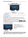
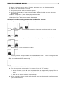
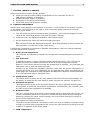
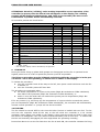
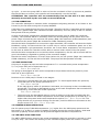
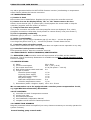
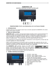
EUROSTER 11WB USER MANUAL 1 EUROSTER 11WB CENTRAL HEATING SYSTEM CONTROLLER MANUFACTURER: P.H.P.U. AS, Polanka 8a/3, 61-131 Poznań, POLAND 1 INTRODUCTION Carefully study this user manual to learn how to correctly operate the EUROSTER 11WB central heating system controller. 2 FIELD OF APPLICATION EUROSTER 11WB is a modern microprocessor-based controller used to control central heating (CH) systems with coal/culm-fired blow boilers and utility hot water (UWH) tank. The controller measures the boiler water temperature and depending on its relation to the preset temperature respectively adjusts flow of the air supplied to the boiler furnace and turns ON/OFF the CH system circulation pump and the UHW system pump. The EUROSTER 11WB controller features the ANTY STOP function that prevents idle pump rotors against seizing. Once the heating season is over, every 14 days the function automatically turns ON the pumps for 30 seconds. To that end the controller must be left powered up. 3 VISIBLE CONTROLLER ELEMENTS 1. 2. 3. 4. 5. 6. 7. 8. 9. 4 230 VAC~ mains input 230 VAC~ power supply to CH pump 230 VAC~ power supply to UHW pump 230 VAC~ power supply to fan Input for UHW temperature sensor cable Input for CH water temperature sensor cable Mains switch LCD display Knob INSTALLATION Hazardous voltages may be present inside the controller and on its cables. Therefore it is expressly forbidden to install the device prior to disconnecting its mains power supply. Only qualified technicians may install the controller. Do not install any devices showing signs of any mechanical damage. EUROSTER 11WB USER MANUAL 2 The procedure: a) Mount the controller: using a pair of supplied nylon nail-it fasteners (anchors) mount the controller box on a wall (or any other suitable supporting structure) using fasteners fix controller cables to the wall. b) Install temperature sensors: do not immerse sensors in liquids nor install them within stream of flue gases install boiler temperature sensor at the boiler point specially designed for that purpose or else on an unshielded boiler outlet pipe (as close to the boiler as possible) install UHW tank temperature sensor at the tank point specially designed for that purpose using hose clips tighten the sensors to their pipes and cover them with thermal insulation. c) Hook up pump power supply cables: connect yellow (or yellow-green) PE wire with the connect blue wire with the N terminal connect brown wire with the L terminal. d) Hook up fan power supply cable: connect yellow (or yellow-green) PE wire with the connect blue wire with the N terminal connect brown wire with the L terminal. terminal terminal e) Verify the connections: check up all cable connections and tighten terminal box lids. f) Hook up the controller: make sure controller cables are protected against incidental cut off plug the controller power supply cable into a 230V/50Hz mains socket equipped with a grounding pin. The controller must not be installed in a place where the ambient temperature may exceed 40ºC. 5 CONTROLLER DISPLAY Elements of the controller display: 1. 2. 3. 4. Name of the controlled parameter (displayed while set point values are browsed/set) Boiler temperature sensor icon Manual operation mode (icon lit while the temperature is manually controlled) Alarm (icon blinks in case of an alarm) EUROSTER 11WB USER MANUAL 3 5. 6. 7. 8. 9. State of the heat source (boiler) furnace – animated icon, see description below Fan icon lit while the fan is running UHW pump icon lit while the pump is running CH system pump icon lit while the pump is running UHW tank temperature / menu option number (displayed while set point values are browsed/set) 10. Boiler temperature / other displayed parameter value 11. UHW tank temperature sensor icon 12. Symbol of the “UWH priority” mode of operation Animated icon that visually presents state of the boiler furnace. • Firing up – the boiler has not yet reached its preset temperature: -> • -> -> Normal operation – boiler temperature within hysteresis corridor around the preset: <-> • Blowdown – boiler temperature has exceeded the preset by more than half of the hysteresis: <-> • Overheating – boiler temperature >90ºC: <-> • 6 Furnace put out – the preset has not been attained in spite of 1 hour of firing the boiler up or boiler furnace temperature has dropped below the put-out temperature (set point Błąd: Nie znaleziono źródła odwołania): TURNING THE CONTROLLER ON Turn the controller mains switch (7 in section 3) into the “I” position. Device firmware version No. and compilation date are sequentially displayed for 2 s. “AS” letters are blinking on the display while the ANTY STOP function turns on the pump. State of the system is shown on the display. If the controller is being turned on for the first time: set the desired controller presets (see section 8 below). EUROSTER 11WB USER MANUAL 7 4 FACTORY (DEFAULT) PRESETS Proceed as follows to restore factory presets: 8 Press the knob and while holding it depressed turn the controller off and on. ”Fd” (factory defaults) is displayed. Release the knob. Digit 0 is displayed. Select digit 1 and accept the selection. Check and correct the presets if needed. CONTROLLER PRESETS Shortly after power supply of the controller is turned on, current state of the system is shown on the display. Turn the knob to the right to enter the preset browse/edit mode. General procedure to edit a preset: 1. Turn the knob to select the desired preset (parameter). The controller displays current value of the selected parameter (top) and its number (bottom). 2. Press the knob. The displayed parameter value starts to blink. 3. Set the desired new value and press the knob to accept it or Wait 10 seconds until the displayed parameter value stops blinking in order to abort the edit procedure (to leave the current value intact) Configuration windows are numbered to facilitate manipulations. User may edit the following controller parameters (presets): 1. Boiler preset temperature The controller will attempt to maintain this temperature manipulating boiler fan and CH pump. 2. Fan hysteresis Temperature range, in which controller linearly adjusts fan power. The narrower the preset hysteresis, the smaller fluctuations of the CH system temperature will be. However, a too narrow preset will make the temperature to oscillate – the controller will alternately heat up and cool down the boiler. Initially set the maximum allowable hysteresis, wait until the preset temperature is reached and check if (in such conditions) the fan operates at a power level between set points Błąd: Nie znaleziono źródła odwołania and Błąd: Nie znaleziono źródła odwołania. If so, the hysteresis may be narrowed down. 3. Minimum fan power The lowest power at which the fan may operate. Should be selected experimentally as the power, at which the fan rotor starts to rotate (see fan test function, set point 11). 4. Maximum fan power The highest power at which the fan should operate. Should be selected experimentally as the power, at which the actual boiler temperature (maintained by the controller) was as close to the preset temperature as possible. 5. Blowdown time The fan is turned ON for that period if the controller needs to blow down the furnace (to remove combustion gases out of the boiler). Blowdown time should be long enough to effectively exhaust the gases via the chimney, but on the other hand short enough to prevent boiler temperature rise. 6. Gap between successive blowdowns Time after the last blowdown cycle before a new cycle may be started. It should be long enough to prevent boiler temperature rise, but on the other hand short enough to avoid explosive combustion of the boiler gases. 7. UHW temperature EUROSTER 11WB USER MANUAL 5 Mean tank temperature that the controller will attempt to maintain manipulating the pump. ATTENTION: Too low tank temperatures (35-40ºC) help to grow various bacteria within the tank, including the Legionella bacteria. 8. UHW pump hysteresis Difference between the temperature at which the controller turns the pump on and the temperature at which the controller turns it off (provided boiler is hot enough, see set point 9 below). See section 12 below for details. 9. Boiler-tank temperature surplus The preset tells how much the boiler temperature should exceed the tank temperature (plus a constant value 3ºC) to enable UHW pump engaging without a risk that the tank will chill out. Alternatively the preset tells how close tank/boiler temperatures (minus a constant value 3ºC) will interrupt operation of the UHW pump. 10. UHW priority Cold UHW tank may heat up faster if this mode of operation is activated: the CH system pump is unconditionally turned OFF, boiler temperature preset is temporarily increased. As soon as the tank temperature reaches the preset, the controller automatically restores the normal operation mode. However, even if this mode of operation is NOT activated, the UHW pump is turned ON provided that the tank temperature is low and the boiler is sufficiently hot. 11. CH pump TURN ON temperature See section 12 for detailed description of conditions in which CH pump is turned ON/OFF. 12. CH pump hysteresis Difference between the temperature at which the controller turns the pump on and the temperature at which the controller turns it off. See section 12 below for details. 13. Boiler temperature sensor correction A constant added to all values measured by boiler temperature (external) sensor to compensate for differences in respect to water temperature inside the boiler. 14. UWH tank temperature sensor correction A constant added to all values measured by tank temperature (external) sensor to compensate for differences in respect to water temperature inside the tank. 15. Put out temperature As soon as actual boiler temperature has dropped below that preset, the controller turns the boiler OFF (the boiler furnace is most probably put out). A too high put out temperature preset may cause the controller to turn the boiler OFF mistakenly. 16. Fan manual operation (test) Display current fan status commanded by the controller (0…100%). Press the knob and modify the parameter value to manually control the fan. Press the knob once more or leave it inactive for 10 seconds to resume automatic mode of control. 17. UHW pump manual operation (test) Display current pump status commanded by the controller (0/1 = pump disengaged/engaged). Press the knob and modify the parameter value to manually control the pump. Press the knob once more or leave it inactive for 10 seconds to resume automatic mode of control. 18. CH pump manual operation (test) Display current pump status commanded by the controller (0/1 = pump disengaged/engaged). Press the knob and modify the parameter value to manually control the pump. Press the knob once more or leave it inactive for 10 seconds to resume automatic mode of control. EUROSTER 11WB USER MANUAL 6 ATTENTION: Should a (colliding) value making impossible correct operation of the controller be preset, then the alarm icon will appear on the display, the colliding presets will be displayed alternatively, and (after a few seconds) the last correct combination of presets will be automatically restored. All controller presets are listed below: No. 1 2 3 4 5 6 7 8 9 10 11 12 13 14 15 16 17 18 1) 2) 9 Parameter Name Boiler preset temperature Fan hystersis Minimum fan power Maximum fan power Blowdown time Gap between successive blowdowns UHW temperature UHW pump hysteresis Boiler-tank temperature surplus UHW priority CH pump TURN ON temperature CH pump hysteresis Boiler temperature sensor correction UWH tank temperature sensor correction Put out temperature Fan manual operation (test) UHW pump manual operation (test) CH pump manual operation (test) default 50 6 45 100 10 6 60 4 10 1 1) 40 4 0 Preset value min 40 2 30 30 0 0 20 2 3 0 1) 20 2 –5 Unit max 80 10 100 100 120 30 70 10 10 1 1) 80 10 5 °C °C % % s min °C °C °C – °C °C °C 0 –5 5 °C 35 – – 2) – 2) 30 0 0 1) 0 1) 50 100 1 1) 1 1) °C % - ) 0=OFF, 1=ON The controller displays values calculated by its algorithm. FIRING UP During the boiler firing-up phase both pumps are disengaged and the fan is operated at its highest power level in order to speed the process up as far as possible. The firing up procedure may be initiated exclusively while the controller is in the putout mode – fan is not operating, no flame icon is visible on the display. To initiate the procedure: turn the controller knob all the way to the left, then press it and hold down until the fan is started, or turn the controller power OFF then ON. The procedure is terminated when: the boiler temperature is closer to the preset (Błąd: Nie znaleziono źródła odwołania) than half of the hysteresis (Błąd: Nie znaleziono źródła odwołania), or within 1 hour the boiler has not reached the preset put-out temperature (Błąd: Nie znaleziono źródła odwołania). If for any reason (e.g. self firing up) the temperature of a put-out boiler exceeds the preset put-out temperature (Błąd: Nie znaleziono źródła odwołania5), the controller will automatically resume normal operation i.e. pumps will not be turned OFF. 10 FUELING The fan should be turned OFF for the time the boiler furnace is loaded with new fuel. To this end turn the controller knob all the way to the left while the controller is in its normal operation mode (flame icon visible on the display), then press the knob and hold it down until the flame icon disappears. Fan icon starts to blink alternately with a hand icon – it means that the fan was manually disengaged (all other algorithms are operating normally). Proceed as above to turn the fan ON. Once the fan is back ON, the controller initiates the firing EUROSTER 11WB USER MANUAL 7 up cycle – it turns the pump OFF in order to fire the new batch of fuel up as soon as possible. Should the flame to extinct, the controller will automatically turn the fan OFF. ATTENTION: The controller will not automatically turn the fan OFF if it was earlier manually turned OFF by the user and not turned back ON. 11 FAN OPERATION The controller attempts to maintain boiler temperature adjusting amount of air blown to the furnace by the fan and turning the CH pump ON/OFF. Cold boiler may sweat during the firing-up period. Therefore the fan is operating at the highest power level (preset Błąd: Nie znaleziono źródła odwołania) and the pump is OFF to shorten that period as far as possible. As soon as the boiler temperature has approached the preset (and is within the hysteresis corridor), the controller starts to smoothly control air flow adjusting the fan power level. Fan power range is limited by the minimum fan power (Błąd: Nie znaleziono źródła odwołania) and the maximum fan power (Błąd: Nie znaleziono źródła odwołania) presets. Should the boiler temperature to exceed the upper threshold, the controller will start the boiler blowdown cycling. In that mode the fan is used only to remove combustion gases out of the furnace. Blowdown cycle parameters should be set so that boiler temperature will drop down to the level at which the controller will be able to resume linear control of the fan power. Should the boiler temperature to exceed the alarm temperature, the fan will be turned OFF for good. Overheating is signaled by pulsing of the controller display. Should the boiler temperature to drop down below the put-out preset (Błąd: Nie znaleziono źródła odwołania), the fan will be turned OFF. The pumps will be operated normally. 12 PUMP OPERATION CH pump is engaged as soon as boiler temperature Tboiler exceeds boiler preset temperature Tpreset by more than half of hysteresis Hpump: Tboiler > Tpreset +Hpump/2 The pump is disengaged as soon as the temperature drops down below the preset by more than half of the hysteresis: Tboiler < Tpreset – Hpump/2 Decision to turn UHW pump is made in two stages: • The pump is turned ON if the tank temperature Ttank has dropped below the preset by more than half of the pump hysteresis Hpump: Ttank < Tpreset - Hpump/2 If the UWH priority mode of operation is activated, the CH pump is then unconditionally turned OFF. The pump is disengaged as soon as the tank temperature has exceeded the threshold by more than half of the hysteresis: Ttank > Tpreset + Hpump/2 • The pump may be disengaged without a risk of chilling out the tank provided that the difference between the boiler temperature and the tank temperature is at least by 3 ºC higher than the preset boiler-tank temperature surplus Tboiler – Ttank > Tsurplus+3ºC. The pump should run (to prevent chilling out the tank) until the difference decreases to the surplus minus 3ºC, Tboiler – Ttank < Tsurplus-3ºC. 13 SUMMER SEASON OPERATION Set CH system pump TURN ON temperature (11) higher then the UHW pump preset and the fan preset (e.g. to 80°C) in order to disable CH system during the summer season. UHW tank will heat up quickly and the boiler will be protected against excessive temperatures. 14 THE ANTY-STOP FUNCTION The ANTY-STOP function turns on the pump immediately after the controller is turned on, then every 14 days. “AS” letters are blinking on the controller display while the function is active. EUROSTER 11WB USER MANUAL 8 Any alarm generated while the ANTY-STOP function is active (overheating or temperature sensor failure) aborts the function execution. 15 TROUBLESHOOTING a) Device is dead Burnt mains fuse or ROM failure. Replace the fuse or have the controller serviced. b) Sensor icon on the display blinks, “Sh” or “OP” letters next to the icon Sensor circuit shorted (Sh) or opened (OP). Check/replace the sensor cable or ship the controller (together with the sensor) to service. c) Pump or fan does not operate Turn on the controller and make sure that pump/fan icons are displayed. If so, check pump/fan connections. Otherwise check presets or restore factory ones (see section 7) d) Fan is operating continually Blowdown gap (6) set to 0 – correct the preset. e) Boiler is overheating Blowdown time (5) too long or blowdown gap (6) too short – correct the preset. A too large fan power level (3, 4) – correct the presets. Throttle down the fan. f) Controller emits a buzzling sound Loose coils in interference filter. The symptom does not impact correct operation in any way. g) Controller knob operates erratically Pulse generator failure. Have the controller serviced. 16 COMPATIBILITY WITH STANDARDS/CERTIFICATES The EUROSTER 11WB controller meets all requirements of the EMC and the LVD EU Directives. The CE Conformity Declaration is available on the http://www.euroster.com.pl Internet webpage. 17 SPECIFICATIONS a) b) c) d) e) Mains Current consumption Fan output rated load Both pump outputs rated total load Length of cables: Controller power supply CH pump power supply UHW pump power supply Fan power supply UHW tank temperature sensor CH boiler temperature sensor f) Dimensions (width x height x depth) 230 V 50Hz max. 7 mA (1.6 W) 0.5 A (fan power < 100 VA) 2A 1.5 m 1.5 m 1.5 m 1.5 m 5m 1,5 m 150 x 90 x 54 mm We recommend to use a fan equipped with a reactive power compensation circuit, e.g. type WBS manufactured by Konwektor. 18 KIT CONTENTS a) b) c) d) e) controller box with 2 temperature sensors sensor hose clips box fasteners/anchors this Installation & Operation Manual template to drill holes for fasteners/anchors 19 CONNECTION DIAGRAM Diagram presented below is simplified (not every element necessary to correctly operate the system is shown). Central heating pump control mode EUROSTER 11WB USER MANUAL 9 1. EUROSTER 11WB controller 2. 3. 4. 5. 6. 7. 8. 9. UHW tank temperature sensor UHW tank UHW pump CH boiler Fan Temperature sensor CH pump Radiator (heat load) 20 ELECTRONIC WASTE MANAGEMENT INFORMATION We made every effort to get as a long controller lifetime as possible. However, the device is subject to natural tear and wear. We ask you to have a controller that will not meet your requirements any more brought in to an electronic waste management facility. Electronic waste is collected free of charge by local distributors of electronic equipment. Inappropriate management of electronic waste may lead to an unnecessary environment pollution. Cardboard boxes should be disposed of at a paper recycling facility. EUROSTER 11WB USER MANUAL 10 EUROSTER 11WB CONTROLLER WARRANTY CERTIFICATE Warranty terms: 1. Warranty is valid for 24 months from the controller sale date. 2. Warranty is valid exclusively on the territory of Poland. 3. Claimed controller together with this warranty certificate must be supplied to the seller or directly mailed via Poczta Polska mail operator to the manufacturer. 4. Warranty claims shall be processed within 14 business days from the date the manufacturer has received the claimed device. 5. Controller may be repaired exclusively by the manufacturer or by other party clearly authorized by the manufacturer. 6. Warranty becomes invalidated in case of any mechanical damage, incorrect operation and/or making any repairs by unauthorized persons. 7. This consumer warranty does not exclude, restrict nor suspend any right of the Buyer ensuing if the product would not meet any of the sale contract terms. ........................................................................................................................ sale date serial number/date of manufacture signature/stamp Service phone (48) 655-71-20-12 Business entity that issued this warranty certificate: P.H.P.U. AS Agnieszka Szymańska-Kaczyńska, Chumiętki 4, 63-840 Krobia, Poland


![CDNXL_60_RETAIL_SALES [MetaTexis] [Final version]](http://vs1.manualzilla.com/store/data/005704456_1-17a983fab827ed2fd4ed28ca910215ca-150x150.png)