1
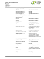
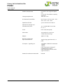
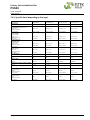
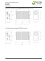
Rectifier PSS30 USER MANUAL Eltek_UM_PSS30_E_R2.0 Primary Switch Mode Rectifier PSS30 User manual Page 2 (28) Notes to this manual ATTENTION! Read this manual before installing and commissioning the specified module. This manual is a part of the delivered module. Familiarity with the contents of this manual is required for installing and operating the specified module. The function description in this manual corresponds to the stage of technology at the date of publishing. Technical changes and changes in form and content can be made at any time by the manufacturer without notice. There are no obligations to update the manual continually. The rules for prevention of accidents for the specific country and the general safety rules in accordance with IEC 364 must be observed. The module is manufactured in accordance with applicable DIN and VDE standards such as VDE 0106 (part 100) and VDE 0100 (part 410). The CE marking on the module confirms compliance with EU standards 2006-95-EG (low voltage) and 2004-108-EG (electromagnetic compatibility) if the installation and operation instructions are followed. Supplier: FAX Email Internet ELTEK DEUTSCHLAND GmbH BU Industrial Schillerstraße 16 D-32052 Herford + 49 (0) 5221 1708-210 + 49 (0) 5221 1708-222 Info.industrial@eltek.com http://www.eltek.com Please note: No part of this document may be reproduced or transmitted in any form or by any means electronic or mechanical, including photocopying and recording- for whatever reason without the explicit written permission of Eltek Deutschland GmbH. Changes and errors excepted. 2011. ELTEK DEUTSCHLAND GmbH. All rights reserved. Eltek Deutschland GmbH ©2011 Eltek_UM_PSS30_E_R2.0 Primary Switch Mode Rectifier PSS30 User manual Page 3 (28) Revision history Revision: 2.0 Date: 2011-01-18 Revision Description of change Writer Date 00 EVI layout and additional pictures inserted, minor text modifications (based on the original version “PSS30_E1_20071023.doc”) RTH 2008-10-06 01 Minor text modifications. RTH 2010-11-25 2.0 New revision numbering (X.X) introduced; minor text modifications. RTH 2011-01-18 Eltek Deutschland GmbH ©2011 Eltek_UM_PSS30_E_R2.0 Primary Switch Mode Rectifier PSS30 User manual Page 4 (28) Contents A. Safety instructions ........................................................................................................... 5 B. Electronic waste disposal ................................................................................................ 5 1. General ................................................................................................................................. 6 2. Type range........................................................................................................................... 6 2.1 Available options and accessories: ..................................................................................................... 7 3. Start up procedure ............................................................................................................ 8 4. Operation ............................................................................................................................. 8 5. Functions ............................................................................................................................. 9 5.1. Circuit diagram ....................................................................................................................................... 9 5.2 Electrical function description ........................................................................................................... 10 5.2.1 Electrical insulation ................................................................................................................... 10 5.2.2 Input ............................................................................................................................................. 10 5.2.3 Output .......................................................................................................................................... 10 5.2.4 Dynamic regulation of the output voltage ........................................................................... 11 5.2.5 RFI suppression .......................................................................................................................... 11 5.2.6 CAN-Bus interface ..................................................................................................................... 11 5.3 Monitoring............................................................................................................................................... 11 5.3.1 Mains voltage monitoring ........................................................................................................ 11 5.3.2 Operation monitoring ................................................................................................................ 12 5.3.3 Monitoring „boost charge“ ....................................................................................................... 12 5.3.4 Monitoring „constant current operation“ ............................................................................. 12 5.3.5 Output voltage low ................................................................................................................... 12 5.3.6 Output voltage high .................................................................................................................. 12 5.3.7 Protection against overheating/collective failure ............................................................. 12 5.3.8 Signals.......................................................................................................................................... 13 5.4 Output and threshold adjustment .................................................................................................... 13 6. External functions .......................................................................................................... 14 6.1 Output voltage sensor leads .............................................................................................................. 14 6.2 Temperature compensation of the charging voltage ................................................................... 14 6.3 External switch ON/OFF function ...................................................................................................... 14 6.4 Discharge test ....................................................................................................................................... 15 6.5 Boost charge mode .............................................................................................................................. 15 7. Operation elements and connectors.......................................................................... 16 7.1 Front view/operation elements 24/48/60/110V version ........................................................... 16 7.2 Front view/operation elements 220V version................................................................................ 17 7.3 Electrical connectors ........................................................................................................................... 18 8. Maintenance .................................................................................................................... 21 9. Trouble shooting ............................................................................................................. 22 9.1. No output voltage ............................................................................................................................... 22 9.2. Deviation of the output voltage ....................................................................................................... 22 10. Technical data ............................................................................................................... 23 10.1. General technical data ..................................................................................................................... 23 10.2. Specific data (depending on the type) ......................................................................................... 26 10.3. Dimensional drawings, PSS30 (24, 48, 60 and 110V version) .................................................. 27 10.4. Dimensional drawings, PSS30 (220V version) ............................................................................. 27 Eltek Deutschland GmbH ©2011 Eltek_UM_PSS30_E_R2.0 Primary Switch Mode Rectifier PSS30 User manual Page 5 (28) A. Safety instructions Warning! Because several components of operating electric devices are charged by dangerous voltage, the improper handling of electric devices may cause accidents involving electrocution, injury, or material damages. • Operation and maintenance of electrical modules must be performed by qualified skilled personnel such as electricians in accordance with EN 50110-1 or IEC 60950. • Install the module only in areas with limited access to unskilled personnel. • Before starting work, the electrical module must be disconnected from mains. Make sure that the module is earthed. • Do not touch connector pins as they can be charged with dangerous voltage up to 30 seconds after disconnection. • Only spare parts approved by the manufacturer must be used. B. Electronic waste disposal The correct disposal of electronic waste is the responsibility to recycle discarded electronic equipment and is necessary to achieve the chosen level to protect human health and the environment. In the case of waste disposal of your discarded equipment we recommend to contact a professional waste management company. Eltek Deutschland GmbH ©2011 Eltek_UM_PSS30_E_R2.0 Primary Switch Mode Rectifier PSS30 User manual Page 6 (28) 1. General The primary switched mode rectifier type PSS30 (named PSS in the following) delivers an output power to a maximum of 3.0kW. Typical applications are DC power supplies, uninterruptable power supplies with parallel connected batteries. Rectifiers of type PSS have good dynamic regulation properties at input voltage changes and load variations. It works with an IV line according to DIN 41772 and is a connection unit, ready for integration in system cabinets with 19“ standard frame according to DIN 41494. The operation elements, measurement instruments and input/output connectors are fitted on the front panel of the module. Parallel operation of several modules is possible (with or without decoupling diodes at the output side). In this case the modules operate with decreased line or in current sharing mode (adjustable at factory). In the current sharing mode the variations of the output currents of the modules are ≤ ±5 % of the nominal output current. An internal active decoupling circuit is available as option. PSS modules also operate single side grounded or ungrounded at input and output. 2. Type range Type designation Material code Input voltage (VAC) Output voltage (VDC) Output current (ADC) PSS30/24-80-CAN 100-030-140.00 230 24 80 PSS30/48-50-CAN 100-030-150.00 230 48 50 PSS30/60-40-CAN 100-030-160.00 230 60 40 PSS30/110-22.3-CAN 100-030-170.00 230 108 22.3 PSS30/220-11.1-CAN 100-030-180.00 230 216 11.1 PSS30/220-11.1-Relay 100-030-180.01 230 216 11.1 Eltek Deutschland GmbH ©2011 Eltek_UM_PSS30_E_R2.0 Primary Switch Mode Rectifier PSS30 User manual Page 7 (28) 2.1 Available options and accessories: Article Material code Connector set for input/output <40A 880-100-STK.01 Connector set for input/output >40A 880-100-STK.02 Connector set for input/output, PSS 220V 880-100-STK.03 Temperature sensor (LM335) integrated in a terminal end M5, with 4m connection wire 19“ sub rack, 7U 880-300-TMP.01 880-MEC-BGT7.00 Photo: 19“ sub rack, 7U, for the integration of three rectifiers PSS Eltek Deutschland GmbH ©2011 Eltek_UM_PSS30_E_R2.0 Primary Switch Mode Rectifier PSS30 User manual Page 8 (28) 3. Start up procedure Before connecting to the input voltage, it should be checked that the voltage information on the type plate corresponds to the available voltage and also that the polarity corresponds to the connection plan of the plug. The mains connection is done via a plug at the front side. The protective conductor should be generally connected (protection class 1, leakage current ≤ 3.5mA). Important: If one pole is grounded at the output side, the module has to be connected with an additional non-fused earthed conductor wire on the earth screw (left side on front panel). In this case the PE wire should not be connected to the input connector to prevent earth circuit. This is very important for paralleled modules without decoupling diodes at the output side. The DC output and signal contacts have to be connected with a SUB-MIN-D-connector, type 21WA4. For modules with an output current >40A two heavy-duty contacts are paralleled. In this case it is important that both contacts are symmetrically loaded. The current must be ≤40A per each contact. The signalling contacts for monitoring, sense links and active current sharing mode are also included in the output connector. The rectifier has big capacitors at the output. If you connect a switched off module to a battery or other modules which operates in parallel, a high capacitor charge current will occur. This current can destroy the contacts on the output connector. You can avoid this effect considering the following rules: • • • • Switch on the PSS module before connecting the output plug Disconnect the DC bus by switch or fuse Charge the capacitors using a resistor (approx. 1 Ohm/V) Use decoupling diodes at the output side After switching off, the capacitors are still fully charged. The discharge time is approx. 4 sec. for the input and approx. 15 sec. for the output side. The rectifier is forced-cooled with fan. The ambient temperature has to be lower than 45 °C. If more than one sub rack mounting level is used in one cabinet there must be a difference between two mounting levels of 3U (approx. 130mm) for an unobstructed airflow. The temperature within the cabinet should not be higher than 40 °C. If there is a higher temperature the life time of the modules will be decreased. The internal losses per module are approx. 260 up to 290W (depending on the type). 4. Operation All operation elements are fitted on the front panel of the module. The function of each individual operation element is described on the following pages. See also section 7. “Operation elements and connectors”. Eltek Deutschland GmbH ©2011 Eltek_UM_PSS30_E_R2.0 Primary Switch Mode Rectifier PSS30 User manual Page 9 (28) 5. Functions 5.1. Circuit diagram Picture: Schematic Block Diagram PSS30 Eltek Deutschland GmbH ©2011 Eltek_UM_PSS30_E_R2.0 Primary Switch Mode Rectifier PSS30 User manual Page 10 (28) 5.2 Electrical function description Rectifiers of type PSS consist of following main parts: 1. 2. 3. 4. 5. 6. 7. 8. 9. 10. Line filter to reduce the high-frequency transients produced by the device as well as damping the transients and noise voltage which are superimposed on the mains. Mains rectifier with switched step-up-converter (operation frequency 100 kHz) to transform the input voltage in a pre-regulated DC voltage of approx. 380V and to control the waveform of the input current (sinusoidal) as well as to control the power factor (>0.99). An additional function is the limitation of inrush current. Transistor bridge to transform the 380VDC to a pulse width modulated AC voltage with a frequency of 100KHz. HF transformer for the decoupling of the primary and secondary side and adaptation of the voltage level to the secondary side. Rectifier diodes LC filter to reduce the voltage ripple at rectifier output. Output filter for RFI suppression and to reduce the noise level on DC line. Internal power supply to supply the primary and secondary control units with potential separation. Controlled system, opto-decoupled. Adjustment panel for adjustment of output parameters, signals and measurement instruments. 5.2.1 Electrical insulation Due to the construction principle of the module (module parts) and separated wiring of mains input and DC output, the PSS meets the following standards: • • Devices with Vo ≤ 60VDC protection against dangerous body currents through low voltage with safe electrical decoupling according to EN 60950 and VDE 0100. Devices with Vo > 60VDC saved electrical decoupling to Vo = 220VDC according to EN 60950 and VDE 0160. 5.2.2 Input The input is protected by 2-pole circuit breaker. This circuit breaker is also used as on/off-switch. The MCB is -seen from the mains input side- connected ahead of the input filter. An additional internal fuse is used to protect the controller. The rectifier has a current limitation which limits the inrush current to the level of the nominal input current. 5.2.3 Output The output line is an IV-line according to DIN 41772 /DIN 41773. Active current sharing mode or decreased charge line (-1% at 100% Inom) is possible. Serially the decreased charge line is factory preset. The output is sustained short circuit proof (constant current control). It is possible to use three different output voltages: 1. Voltage for trickle charge 2. Boost charge 3. Battery test The output voltage for trickle charge is standard set. For the use of “Boost charge” or “Battery test”, the pins of the signal connectors are to be connected as described in section 7.3 “Electrical connectors”. Eltek Deutschland GmbH ©2011 Eltek_UM_PSS30_E_R2.0 Primary Switch Mode Rectifier PSS30 User manual Page 11 (28) 5.2.4 Dynamic regulation of the output voltage At load jumps between 10 % and 90 % Inom / 90 % and 10 % Inom the dynamic voltage difference is max. ± 3 % and is corrected in max. 1.5 ms to static levels. 5.2.5 RFI suppression Modules of type PSS meet the standard VDE 0878 T1 and EN 55011/55022 class ‘B’. The output ripple is (psophometrically measured according to CCITT) < 1.2mV (24V), < 1.8mV (48V and 60V). 5.2.6 CAN-Bus interface The rectifier PSS is equipped with a serial CAN-Bus interface. Two CAN connectors (RJ11, 6-pole) are fitted at the front side of the 24V - 110V version. For the 220V version the CAN-Bus connection is integrated in the front side connector X4. Several modules in a system or parallel connection can be controlled and monitored through the CANBus by a central DC controller unit MU1000C. The following parameters of a specific rectifier unit can be controlled or monitored: • • • Output voltage Output current Module status Furthermore, the rectifier unit receives all threshold values through the CAN-Bus from the DC controller unit. REMARK: If several paralleled rectifiers are controlled by a central DC controller unit, it is important to assign an explicit CAN-Bus address to each individual rectifier (see section 5.4). 5.3 Monitoring 5.3.1 Mains voltage monitoring Mains voltage monitoring; signalling with LED "Switch symbol", criterion: output voltage of step-upconverter ≥ 370 V, at the same time operation monitoring of step-up-converter (equivalent to main voltage of approx. ≥ 195 VAC; depends on the load). The LED is dark if the mains voltage is low or the step-up-converter is out of order. This signal is included in the collective failure signal of the rectifier. Additional there is an optocoupler signal (mains O.K.). For high input voltages (approx. >270VAC) there is implied an automatic switch off function. Eltek Deutschland GmbH ©2011 Eltek_UM_PSS30_E_R2.0 Primary Switch Mode Rectifier PSS30 User manual Page 12 (28) 5.3.2 Operation monitoring Functional monitoring; signalling with LED "VO1", criterion: output voltage ≥ 97 % of adjusted output voltage without constant current regulation; ≥ 85 % of adjusted output voltage with constant current regulation. The signalling threshold of this monitoring automatically follows the adjusted nominal output voltage. This signal is included in the collective failure signal of the rectifier. Additional there is an optocoupler signal (Vo O.K.) available. At operation with internal decoupling diodes the voltage is measured ahead of the diodes. 5.3.3 Monitoring „boost charge“ If „boost charge“ is activated (see section 6.5), LED V02 is ON, LED V01 is OFF. 5.3.4 Monitoring „constant current operation“ Constant current operation (output current limiting active) is signalled with a yellow LED I0. 5.3.5 Output voltage low Output voltage low monitoring; signalling with LED "V<", criterion: Output voltage is higher than adjusted level V<; this signal is included in the collective failure signal of the rectifier. This signal has its own relay contact on the signalling connector. If the voltage value is O.K., pin 13 and pin 17 of X2 are closed. 5.3.6 Output voltage high Output voltage high monitoring; signalling with LED "V>", criterion: output voltage higher than adjusted level V>. This signal is included in the collective failure signal of the rectifier. If there is an error, the LED is ON and the rectifier internally switches off. You have to reset the unit by ON/OFF switch. 5.3.7 Protection against overheating/collective failure A collective failure is signalled with the LED “Bell symbol”. Furthermore overheating is signalled; criterion: Temperature of the heat sink > 90°C (the unit switches OFF). This signal is included in the collective failure signal. You have to reset the unit by ON/OFF switch. Eltek Deutschland GmbH ©2011 Eltek_UM_PSS30_E_R2.0 Primary Switch Mode Rectifier PSS30 User manual Page 13 (28) 5.3.8 Signals The following signals are available as potential-free optocoupler signals: 1. "Vo O.K.", 2. "Mains O.K." 3. Constant current mode “Iconst" The maximum contact load is 30V/5mA. The optocouplers switch OFF at signal 1. and 2., they switch ON at signal 3. The collective failure signal is delayed for approx. 10s and is available (as well as the signal V>) via a potential-free relay contact. If a failure exists, the relay switches OFF. For PSS30, 24/48/60/110V version: The relay contacts between pin 14 and pin 15 of X2 are open and between pin 15 and pin 16 are closed at failure. For PSS30, 220V, only relay version: The relay contacts between pin 12 and pin 13 of X4 are open and between pin 13 and pin 14 are closed at failure. The following monitoring items are included in the collective failure signal: 1. 2. 3. 4. 5. Mains voltage monitoring Operation monitoring Output voltage low Output voltage high Over temperature 5.4 Output and threshold adjustment The adjustment of output values and monitoring thresholds are very easy. All values are to be adjusted with front keys; the actual values are indicated with the front side digital displays. At normal operation the top display shows the output voltage (VO1, VO2 or VO3 depending on the selected operation mode) and the bottom display shows the output current (Io). In the adjustment mode, the top display shows the name of the parameter, the bottom display shows the related value. For any adjustment please follow these instructions: • • • • • • press both keys UP/DOWN (↑↓) together for a short time; the rectifier changes to adjustment mode press the key UP (↑) or DOWN (↓) to change the adjustment parameter (see the following table) press both keys UP/DOWN (↑↓) together for a short time; the rectifier changes to value change mode press the key UP (↑) or DOWN (↓) to change the adjustment value (if you hold the key, the value changes quicker) press both keys UP/DOWN (↑↓) together for a short time; the rectifier changes back to adjustment mode (at this moment the changed value will be stored) press both keys UP/DOWN (↑↓) for approx. three sec. to change to the operation mode You are able to leave the adjustment mode at any time pressing the keys UP/DOWN (↑↓) for approx. three sec. Eltek Deutschland GmbH ©2011 Eltek_UM_PSS30_E_R2.0 Primary Switch Mode Rectifier PSS30 User manual Page 14 (28) Adjustable parameters in the adjustment mode: Displayed short term of the parameters VO1 VO2 VO3 Io V< V> t Adr Parameter meaning trickle charge voltage boost charge voltage (see section 6.5) voltage at discharge test (see section 6.4) output current output voltage low threshold (see section 5.3.5) output voltage high threshold (see section 5.3.6) temperature coefficient for temperature compensation of the charge voltage (see section 6.2) change CAN-Bus address The threshold values for mains/step-up-converter and over heating are not changeable. The threshold values of DC voltage low (V<) and DC voltage high (V>) can be individually set within a limited adjustment range. For more information regarding the adjustment ranges and factory preset values see section 10. “Technical data”. 6. External functions 6.1 Output voltage sensor leads Voltage losses at wires or diodes are to be compensated with sense links for the output voltage. The maximum regulation difference is approx. 4 % of the nominal voltage. Cable break at sense links, confusing of poles or short circuit can not damage the rectifier. At cable break of the sense link, a voltage increase of max. 4% is possible. 6.2 Temperature compensation of the charging voltage For the use of closed batteries we recommend temperature-controlled compensation of the charge voltage. Connect an external active temperature sensor (option) to the signalling connector. The standard set temperature coefficient is -4mV/K per cell (within a temperature range of 0-50 °C). The basic temperature is 20°C. The coefficient can be adjusted between 0 to -6mV/K per cell (see section 5.4). Connect the sensor using a 2-pole wire (0.25mm2). It can be directly mounted on top of the battery or on battery poles. At great distances (> 2m) we recommend the use of a shielded wire with connection of the shield to rectifiers ground. 6.3 External switch ON/OFF function The rectifier can be externally switched on/off by applying an external DC voltage via external switch to the respective pins according to section 7.3. The output of the PSS rectifier switches OFF, if the external voltage is applied. In this case switch-off does not result in a collective failure signal! The input is potential free due to the use of an optocoupler and meets the supposition for safe electrical decoupling to mains and output side. The signalling voltage is 10-24V, the internal resistance is 2.7kOhm. The input is protected against reversed polarity. At higher supply voltages the current in the control circuit has to be limited to approx. 5-7mA using a series resistor (e. g. 6.8kOhm at 48/60VDC). Eltek Deutschland GmbH ©2011 Eltek_UM_PSS30_E_R2.0 Primary Switch Mode Rectifier PSS30 User manual Page 15 (28) 6.4 Discharge test It is possible to test the capacity of a battery which operates in parallel with the rectifier. To select the discharge test mode you have to connect –Vo to pin 2 of the output connector X2 (see section 7.3). The discharge test voltage can be adjusted by the user (parameter VO3; see section 5.4). If the discharge test mode is active, the LED VO1 is ON; LED VO2 is OFF. 6.5 Boost charge mode The rectifier module has a second charge line (boost charge line). To select this mode you have to connect +Vo to pin 2 of the output connector X2 (see section 7.3). The boost charge mode is signalized by LED VO2. The voltage value can be adjusted by the user (see section 5.4). NOTE: For 60/110/220V units: For the connection to +VO an additional series resistor is to be used (60 V: 18kOhm; 110 V: 56kOhm; 220V: 150kOhm). Eltek Deutschland GmbH ©2011 Eltek_UM_PSS30_E_R2.0 Primary Switch Mode Rectifier PSS30 User manual Page 16 (28) 7. Operation elements and connectors 7.1 Front view/operation elements 24/48/60/110V version Digital display for output voltage and -current/ indication of the parameters and related values in the adjustment mode LED indicators Adjustment keys „UP“ and „DOWN“ Input-side fuse; ON-/OFF switch Locking slide for the DC connector DC output connector X2 (& signals) Two CAN-Bus connectors (RJ11, 6-pole) Mains input connector X1 PE connector (M4 bolt) Eltek Deutschland GmbH ©2011 Eltek_UM_PSS30_E_R2.0 Primary Switch Mode Rectifier PSS30 User manual Page 17 (28) 7.2 Front view/operation elements 220V version Digital display for output voltage and -current/ indication of the parameters and related values in the adjustment mode LED indications Adjustment keys „UP“ and „DOWN“ Input-side fuse; ON-/OFF switch DC output connectors X2 Signals/CAN-Bus connectors X4 Mains input connector X1 PE connector (M4 bolt) Eltek Deutschland GmbH ©2011 Eltek_UM_PSS30_E_R2.0 Primary Switch Mode Rectifier PSS30 User manual Page 18 (28) 7.3 Electrical connectors AC-mains input (GDM-connector) for all PSS30 versions (connector X1) X1, pin 1 2 PE Function L1 - Input N - Input PE X1 DC output and signalling contacts (SUB-MIN-D-connector 21WA4), for 24, 48, 60 and 110V versions (connector X2): X2, pin A1 A2 A3 A4 1 2 3 4 5 6 7 8 9 10 11 12 13 14 15 16 17 Function (+) - output (+) - output (additional for Io ≥ 40A) (-) - output (additional for Io ≥ 40A) (-) - output (+) - output voltage sense link signal input discharge test mode / boost charge mode 1) optocoupler emitter optocoupler collector "Mains O.K." optocoupler collector "Vo O.K." optocoupler collector "Io" temperature sensor (+) 2) control wire for active current sharing 3) (-) - output voltage sense link analogue ground (for temperature sensor (-), active current sharing) (+) external switch on/off 4) (-) external switch on/off relay contact V< , N/O 5) relay contact collective failure , N/O relay contact collective failure , COM relay contact collective failure , N/C relay contact V< , COM REMARK: The legend of the items 1) … 5) follows on the next page. Eltek Deutschland GmbH ©2011 Eltek_UM_PSS30_E_R2.0 Primary Switch Mode Rectifier PSS30 User manual Page 19 (28) LEGEND: 1) Tri-state-input: pin 2 at -VO = discharge test mode pin 2 at +VO = boost charge mode NOTE: For 60/110/220V units: For the connection to +VO an additional series resistor is to be used (60 V: 18kOhm; 110 V: 56kOhm; 220V: 150kOhm). 2) Connection of temperature sensor with 2-pole wire to pin 7(+) and pin 10 (-) NOTE: If several modules are paralleled, pin 7 of each individual unit and pin 10 of each individual unit has to be connected. 3) At active current sharing mode of paralleled units the pin 8 of each individual module has to be connected. ATTENTION: If active current sharing mode is enabled, the use of external decoupling diodes and fuses as well in minus on the output side is not allowed. 4) External switch on/off with optocoupler: internal series resistor 2.7kOhm, Imin< = 5mA, Imax = 10mA (see section 6.3). NOTE: The input is potential free with safe electrical decoupling to primary side and with 500VDC to secondary side. 5) The relay outputs are potential free with safe electrical decoupling to primary side and with 500VDC to secondary side. For the 216V version, the DC output and signal connectors are separated. DC output (8xCOMBICON 4mm2) for 220V version (connector X2): X2, pin 1 2 3 4 5 6 7 8 Function (+) - output (+) - output (+) - voltage sense link control wire for active current sharing 6) BUS ground (-) - voltage sense link (-) - output (-) - output Signals (connector X4 = 15 x COMBICON 1.5mm2): Eltek Deutschland GmbH ©2011 Eltek_UM_PSS30_E_R2.0 Primary Switch Mode Rectifier PSS30 User manual Page 20 (28) Pin assignment of X4 for PSS30/220V with signalling relay (without CAN-Bus) X4, pin 1 2 3 4 5 6 7 8 9 10 11 12 13 14 15 Function (+) external switch on/off 4) (-) external switch on/off optocoupler emitter optocoupler collector "Mains O.K." optocoupler collector "VO O.K." optocoupler collector "IO" BUS ground signal input discharge test mode / boost charge mode 1) temperature sensor (+) 2) control wire for current sharing mode 3) relay contact V< , NO 5) relay contact collective failure , NO 5) relay contact collective failure , COM relay contact collective failure , NC 5) relay contact V< , COM Pin assignment of X4 for PSS30/220V with CAN-Bus (without signalling relay) X4, pin 1 2 3 4 5 6 7 8 9 10 11 12 13 14 15 Function (+) external switch on/off 4) (-) external switch on/off optocoupler emitter optocoupler collector "Mains O.K." optocoupler collector "VO O.K." optocoupler collector "IO" BUS – GND signal input discharge test mode / boost charge mode 1) temperature sensor (+) 2) control wire for current sharing mode 3) CVCC + CAN-H CAN-L CVSS Not connected REMARK: The legend of the items 1) … 6) follows on the next page. LEGEND: Eltek Deutschland GmbH ©2011 Eltek_UM_PSS30_E_R2.0 Primary Switch Mode Rectifier PSS30 User manual Page 21 (28) 1) Tri-state-input: pin 8 at -VO = discharge test mode pin 8 at +VO = boost charge mode NOTE: For the connection to +Vo an additional series resistor (150kOhm for the 220V version) is to be used. 2) Connection of a temperature sensor with 2-pole wire to pin 9 (+) and pin 7 (-) NOTE: If several modules are paralleled, pin 9 of each individual unit and pin 7 of each individual unit has to be connected. 3) At active current sharing mode of paralleled units pin 10 of each individual module has to be connected. ATTENTION: If active current sharing mode is enabled, the use of external decoupling diodes and fuses as well in minus on the output side is not allowed. 4) External switch on/off with optocoupler: internal series resistor 2.7kOhm, Imin< = 5mA, Imax = 10mA (see section 6.3). NOTE: The input is potential free with save electrical decoupling to primary side and with 500VDC to secondary side. 5) The relay outputs are potential free with save electrical decoupling to primary side and with 500VDC to secondary side. 6) At active current sharing mode of paralleled units pin 4 (X2) of each individual module has to be connected. ATTENTION! You can either use version 6) or version 3) for the wiring of the active current sharing mode, but not both in combination! 8. Maintenance In general, the PSS rectifier is maintenance-free. A yearly inspection with following checks is recommended: • Mechanical inspection • Removal of dust and dirt, especially on radiator surfaces • Check for internal dust or humidity Attention! Dust combined with moisture or water may influence or destroy the internal electronic circuits. Dust inside the unit can be blown out with dry compressed air. The intervals between this checks depends on ambient conditions of the installed module. Eltek Deutschland GmbH ©2011 Eltek_UM_PSS30_E_R2.0 Primary Switch Mode Rectifier PSS30 User manual Page 22 (28) 9. Trouble shooting Only skilled and trained technical personnel should carry out the necessary trouble shooting operations at the unit. 9.1. No output voltage - Is the mains voltage present? - Is the mains switched to on-position? - Is the input plug correctly connected? - Is the polarity correct or short circuit at the output? - Paralleled units: incorrect polarity at external decoupling diodes? - Monitoring of output voltage high V> signalize an error (lights LED V>?) → switch the unit off and on again and check the adjusted value of V> (see section 5.4)! If the unit still does not work even though all checks have been done, contact your sales agent or the service department of ELTEK DEUTSCHLAND GmbH. 9.2. Deviation of the output voltage - Operates the module in constant current mode (overload)? → Reduce the load! - Adjustment of output voltage value VO wrong? → Adjust the output voltage to nominal values (see section 5.4)! - Cable break at external sense links? - Voltage losses at decoupling diodes on output side? → Adjust the output voltage to higher level or use sense links! If the unit still does not work even though all checks have been done, contact your sales agent or the service department of ELTEK DEUTSCHLAND GmbH. Eltek Deutschland GmbH ©2011 Eltek_UM_PSS30_E_R2.0 Primary Switch Mode Rectifier PSS30 User manual Page 23 (28) 10. Technical data 10.1. General technical data Nominal input voltage 230VAC -20/ +15% Inrush current 25A at 10ms Recommended mains fuse gL 25A IV line IV line acc. DIN 41 772/ DIN 41773 Emission acc. EN50081-1 Conducted interference voltage acc. EN 55011/EN55022 class "B" Radiated electromagnetic field strength Eltek Deutschland GmbH ©2011 acc. EN 55011/EN55022 class "B" Immunity acc. EN50082-2 Cabinet ESD-test acc. EN61000-4 part 2; 6kV contact; 8kV air discharge HF-field acc. EN61000-4 part 3; 10V/m (30MHz - 1GHz) Power wires Burst-test acc. EN61000-4 part 4; 2kV Surge-test acc. EN61000-4 part 5; 4kV unsymmetric; 2kV symmetric Signal wires Burst-Test acc. EN61000-4 part 4; 2kV Surge-Test acc. EN61000-4 part 5; 2kV unsymmetric Protection (electr.) with safe decoupling at VO≤ 60VDC acc. VDE0100 part 410/11.83 cap. 4.3.2; at 110VDC ≤ VO ≤ 220VDC acc. VDE 0160 5.88 cap. 5.6 Dynamic voltage difference ≤ 3 % at load changes between 10 % - 90 % - 10 % of nominal output current (regulation time ≤ 1 ms) Short circuit capability continuous short circuit proof (constant current control) Eltek_UM_PSS30_E_R2.0 Primary Switch Mode Rectifier PSS30 User manual Page 24 (28) Protection / monitoring / signalling front side 2-pole MCB (16A) Mains monitoring „Mains“ Operation monitoring „VO1 “ Operation monitoring „VO2 “ Output voltage low „V<„ Output voltage high „V>„ Constant current mode „IO“ Over-temperature/general fault green LED green LED green LED green LED with relay contact red LED yellow LED red LED Digital instruments: Ammeter Indication of 00.1 to 99.9ADC Voltmeter Indication of 00.1 to 999VDC External functions signal V< General fault alarm signal via potential-free relay contact (10s time delay) (max. contact load: 24VDC/1A, 120VAC/0.5A) Power measuring discharge test / boost charge for active current distribution voltage values adjustable Temperature compensated voltage regulation External sensor lead connection for output voltage Eltek Deutschland GmbH ©2011 via potential-free contact (max. contact load: 24VDC/1A, 120VAC/0.5A) temperature coefficient 4mV/K per cell with external temperature sensor (optional), temperature coefficient adjustable Signal via optocoupler „VO O.K.“ „Mains O.K.“ Constant current operation „Iconst“ signal via optocoupler External ON/OFF if required Parallel operation max. 10 units, consumer load sharing approx.10% Design 1/3 x 19" unit for mounting in cabinets according to DIN 41494 Protection class IP 20 Cooling Fan cooling Eltek_UM_PSS30_E_R2.0 Primary Switch Mode Rectifier PSS30 User manual Page 25 (28) Ambient temperature Storage temperature Environmental conditions IEC 721 part 3-3 Class 3K3 / 3Z1 / 3B1 / 3C2 / 3S2 / 3M2 Operation altitude up to a maximum of 1500 m Mechanical strength and vibration resistance acc. to VDE 0160 issue. 5.88 Pt. 7.2.2 Finish RAL 7035 (front plate) Dimensions see section 10.3 and 10.4 “Dimensional drawings” Weight: approx. 12.4kg Electrical connectors: Input connection X1 Eltek Deutschland GmbH ©2011 0°C to 45°C for single unit operation 0°C to 40°C for cabinet assembly operation -30°C to + 70°C angular plug type GDM 2011; 3pole DC-output / signalling X2 24-108VDC: SUB-Min-D-connector 21WA4 216VDC: Front side terminals 8x4mm2, COMBICON (DC-output); Front side terminals 15x1.5mm2 (signal contacts) Protective conductor connection bolt M4 Eltek_UM_PSS30_E_R2.0 Primary Switch Mode Rectifier PSS30 User manual Page 26 (28) 10.2. Specific data (depending on the type) Type PSS30/24-80 Input current 10.9AAC Output voltage VO1 (trickle charge) Adjusted value 27.2VDC±1% Adjustment range 23.4 to 28.8VDC Output voltage VO2 (Boost charge) Adjusted value 28.8VDC ±1% Adjustment range 24 to 30VDC Output voltage VO3 (discharge test) Adjusted value 22.2VDC ±1% Adjustment range 20.4 to 24VDC Output current IO Adjusted value 80ADC±2% Adjustment range 40 to 80ADC Type of battery 12 Pb – cells Efficiency 90 % Voltage ripple PSS30/48-50 PSS30/60-40 PSS30/110-22.2 PSS30/220-11.1 12.9AAC 12.9AAC 12.9AAC 12.9AAC 54.5VDC±1% 68.1VDC±1% 122.6VDC ±1% 245.2VDC±1% 46.6 to 57.6VDC 58.5 to 72.0VDC 105 to 130VDC 211 to 260VDC 57.6VDC±1% 72.0VDC±1% 129.6VDC ±1% 259.2VDC±1% 48 to 60VDC 60 to 73VDC 108 to 135VDC 216 to 270VDC 44.4VDC ±1% 55.5VDC ±1% 99.9VDC ±1% 200VDC ±1% 40.8 to 48VDC 51 to 60VDC 91.8 to 108VDC 184 to 216VDC 50ADC ±2% 40ADC ±2% 22.3ADC ±2% 11.1ADC ±2% 25 to 50ADC 20 to 40ADC 11 to 22.3ADC 5.5 to 11.1ADC 24 Pb - cells 30 Pb - cells 54 Pb - cells 108 Pb - cells 91 % 91 % 91 % 91 % ≤20mVpp ≤20mVpp ≤20mVpp ≤100mVpp ≤200mVpp Psophometric ripple according to CCITT ≤1.2mV Monitoring: ≤1.8mV ≤1.8mV --- --- 40.8VDC 51.0VDC 91.8VDC 184VDC 38.4 to 48VDC 48 to 60VDC 86.4 to 108VDC 173 to 216VDC 60VDC 75VDC 135VDC 270VDC 52 to 60VDC 66 to 75VDC 119 to 135VDC 238 to 270VDC DC under voltage V< Threshold value 20.4VDC Adjustment range 19.2 to 24VDC DC over voltage V> Threshold value 30VDC Adjustment range 26 to 30VDC Eltek Deutschland GmbH ©2011 Eltek_UM_PSS30_E_R2.0 Primary Switch Mode Rectifier PSS30 User manual Page 27 (28) 10.3. Dimensional drawings, PSS30 (24, 48, 60 and 110V version) 10.4. Dimensional drawings, PSS30 (220V version) Eltek Deutschland GmbH ©2011 Eltek_UM_PSS30_E_R2.0 Supplier: FAX Email Internet ELTEK DEUTSCHLAND GmbH BU Industrial Schillerstraße 16 D-32052 Herford + 49 (0) 5221 1708-210 + 49 (0) 5221 1708-222 Info.industrial@eltek.com http://www.eltek.com 2011. ELTEK DEUTSCHLAND GmbH. All rights reserved.