1
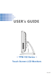
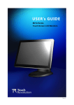
USER’s GUIDE
TPM-193 Series
Touch Screen LCD Monitors
The information contained in this document is subject to change without notice.
This document contains proprietary information that is protected by copyright. All rights
are reserved. Nopart of this document may be reproduced,translated to another language
or stored in a retrieval system, or transmitted by any means, electronic, mechanical,
photocopying, recording, or otherwise, without prior written permission. Windows is a registered
trademark of Microsoft, Inc.
Other brand or product names are trademarks of their respective holders.
Important Recycle Instruction:
Lamp(s) inside this product contains mercury. This product may contain other electronic waste that can be hazardous if not disposed of properly. Recycle or
dispose in accordance with local, state, or federal Laws. For more information,
contact the Electronic Industries Alliance at WWW.EIAE.ORG. For lamp specific
disposal information check WWW.LAMPRECYCLE.ORG.
Table of Contents
Usage Notice
Precautions............................................................................................................................. 1
Introduction
About TPM-193 Series ........................................................................................................... 2
Touch Screen for TPM-193 Series ............................................................................... 3
Package Overview ...................................................................................................... 4
Installation
Product Overview ........................................................................................................
Front View ...............................................................................................................
TPM-193R / TPM-193C Bottom View (Without Stand) ..............................................
TPM-193W Bottom View (Without Stand) .................................................................
Kensington Security Slot ..............................................................................................
VESA Mount for your Monitor.......................................................................................
Start Your Installation ..................................................................................................
Remove the Back Cover ..........................................................................................
Connecting the Display (Figure 1.1) .............................................................................
5
5
5
6
6
7
8
8
9
User Controls
Front Panel Controls ................................................................................................... 11
How to Use the OSD Menus .......................................................................................12
On-Screen Display Menus ..........................................................................................13
Appendix
Troubleshooting ..........................................................................................................14
Warning Signal ...........................................................................................................15
No signal .................................................................................................................15
Going to sleep ........................................................................................................15
Out of range ...........................................................................................................15
Product Dimensions ...................................................................................................16
Compatibility Modes ...................................................................................................17
Touch Screen Driver Installation .................................................................................18
Driver installation process ......................................................................................18
TPM-193R / TPM-193C Driver Install ......................................................................18
TPM-193W Driver Install .........................................................................................19
TPM-193C Optional Capacitive Calibration Tool Install............................................19
Usage Notice
!
!
Warning - To prevent the risk of fire or shock hazards, do not expose
this product to rain or moisture.
Warning - Please do not open or disassemble the product as this may
cause electric shock.
Precautions
Follow all warnings, precautions and maintenance as recommended in this user’s manual to
maximize the life of your unit.
Do:
• Turn off the product before cleaning.
• Touch screen surface may be cleaned using a soft clean cloth moistened with
mild window glass commercial cleaners or 50/50 mixture of water and isopropyl
alcohol.
• Use a soft cloth moistened with mild detergent to clean the display housing.
• Use only high quality and safety approved AC/DC adapter.
• Disconnect the power plug from AC outlet if the product is not going to be used for
an extended period of time.
Don’t:
• Do not touch the LCD Display screen surface with sharp or hard objects.
• Do not use abrasive cleaners, waxes or solvents for your cleaning.
• Do not operate the product under the following conditions:
- Extremely hot, cold or humid environment.
- Areas susceptible to excessive dust and dirt.
- Near any appliance generating a strong magnetic field.
- In direct sunlight.
1
Introduction
About TPM-193 Series
The TPM-193 Series is a 19" flat panel screen with an active matrix, thin-film
transistor (TFT) liquid crystal display (LCD).
Features include:
• Direct Analog signal input
• Active matrix TFT LCD technology
• 1280 x 1024 SXGA resolution
• 19" viewable display area
• 31.5 ~ 81 KHz horizontal scan
• 56.3 ~ 75 Hz high refresh rate
• 0.294mm x 0.294mm pixel pitch
• Auto adjustment function
• Multilingual OSD user control
• Kensington security slot
• 100 mm VESA mount
• Removable base for flexible mounting solutions.
• TPM-193R- 5-wire resistive touch screen with dual RS-232 Serial / USB controller
• TPM-193W - SAW touch screen with USB controller
• TPM-193C - Capactive touch screen with dual RS-232 Serial / USB controller
• Built-in speakers-1W x 2
Touch Screen for TPM-193R
• Analog 5-wire resistive touch screen for finger and stylus input
• Surface: Anti-glare treatment
• Interface: Dual RS-232 Serial/USB controller
• Transmittance: 80±5%
• Driver: Windows® VISTA, XP, 2000, ME, 98, CE, XP Embedded, Linux/Apple® Mac OS
Touch Screen for TPM-193W
• Surface Acoustic Wave (SAW) touch screen for finger and stylus input
• Surface: Anti-glare treatment
• Interface: USB controller
• Transmittance: 90±5%
• Driver: Windows® VISTA 64/32 bits, XP, 2000, 98
2
Touch Screen for TPM-193C
• Analog capacitive touch screen for finger input only
• Surface: Anti-glare treatment
• Interface: Dual RS-232 Serial/USB controller
• Transmittance: 85±5%
• Driver: Windows® VISTA, XP, 2000, ME, 98, CE, XP Embedded, Linux/Apple® Mac OS
3
Package Overview
LCD Display
Power Cord
USB Cable ( A to B)
Audio-in Cable
USB Cable (A to A)
(Option for MSR)
TouchKit CD
DVI-D Cable
(TPM-193X Series Only)
DC Power Supply
(sold separately)
4
VGA Signal Cable
RS-232 Cable
Quick Start Guide
Product Overview
• Front View
• TPM-193R / TPM-193C Bottom View (Without Stand)
Audio
VGA IN
AC IN
DVI IN RS-232
(Option)
USB
DC IN
• TPM-193W Bottom View (Without Stand)
Audio
VGA IN
AC IN
DVI IN
USB
DC IN
5
Kensington Security Slot
The monitor can be secured to your desk or any other fixed object with Kensington lock
security products. The Kensington lock is not included.
6
VESA Mount your monitor
This monitor conforms to the VESA Flat Panel Mounting Physical Mounting Interface
standard which defines a physical mounting interface for flat panel monitors, and
corresponding with the standards of flat panel monitor mounting devices, such as wall and
table arms. The VESA mounting interface is located on the back of your monitor.
To mount the monitor on a swing arm or other mounting fixture, follow the instructions
included with the mounting fixture to be used, please note to mount your monitor to the
devices (either mounting fixture or swing arm) what conforms to the UL listed.
!
Warning!
Please select the proper screws!
The distance between the back cover surface and the bottom of the screw hole
is 8 mm. Please use four M4 screws diameter with the maximum length of 8
mm to mount your monitor.
Please note the mounting stand shall be able to sustain at least 5Kg weight.
7
Start Your Installation
Remove the Back Cover
Please follow these instructions to remove the cover on the back panel of the LCD so that
you can hookup the cables to associated connector.
Figure A
1.
To remove the back cover, follow the arrows in figure A and pull out with your fingers and
the cover should be removed from the stand.
2.
Follow the instructions on P.10 (Figure 11.1) to connect the cables to the appropriate
connectors.
3.
Attach the cover back to the LCD stand by pressing firmly until the tabs snap into place.
You may also keep the cables in order by using the cable organizer.
!
Note!
You can place the LCD flat horizontally to
make it easier to connect the cables. Please
make sure that you place it on an even surface
lest the LCD should be damaged by scratches
or collision.
included cables organizer
8
Connecting the Display (Figure 11.1)
To setup this display, please refer to the following figure and procedures.
1.
2.
3.
4.
5.
6.
7.
!
Be sure all equipments are turned off.
Connect the AC power cord to the power connector on the monitor and the other end
into an electrical outlet (11.1).
Connect the D-SUB or DVI cable from the display’s VGA input connector to the D-SUB
or DVI connector of your host computer and tighten the screws (11.1).
Connect the Audio-In cable from the audio input port of your display to the Audio-out port
of your computer (11.1).
Connect the RS-232 or USB cable from the RS-232 or USB port of your display to the
RS-232 port (11.1) or USB port (11.1) of your computer.
Configure the touch screen. Refer to the “Touch Screen Driver Installation” section on
Page 18.
Once the touch screen is configured, the monitor is ready for use.
Notice!
To ensure the LCD display works well with your computer, please configure the
display mode of your graphics card to make it less than or equal to 1280 x 1024
resolution and make sure the timing of the display mode is compatible with the LCD
display.
We have listed the compatible “Video Modes” of your LCD display in the appendix
(on page 14) for your reference.
9
(Figure 11.1)
10
User Controls
Front Panel Controls
No
/
Icon
Menu
No
Icon
Control
Function
Menu
Menu button
Display the OSD menus
▲
Brightness
Plus
Clockwise
1.Enter brightness of the OSD.
2.To increase value of the adjustment items.
3.Select item clockwise.
▼
Mute
Minus
1.To decrease value of the adjustment items.
2.Select item count-clockwise.
Select
Auto Adjust
Select: Select the adjustment items from OSD menus.
Auto Adjust: Activate the “Auto Adjustment” function to
obtain the optimum image.
Power Switch
Switches on/off the power of the LCD display.
11
How to Use the OSD Menus
1. Press the “MENU” button to pop up the “on-screen menu” and press “▲” or “▼”
to select among the six functions in the main menus.
2. Choose the adjustment items by pressing the “
” button.
3. Adjust the value of the adjustment items by pressing the “▲” or “▼” button.
(1) The OSD menu will automatically close, if you have left it idle for a pre-set time.
(2) To disable the OSD / Power menu buttons, please follow the instructions below:
(Please note: the monitor has to be turned ON with a valid signal preset)
a. Press and hold the “Power” and “Menu” key simultaneously for 1 seconds.
b. The wording “OSD Lock” / “Power Lock” will appear for 2 seconds on the
monitor. This indicates that all the front buttons, with the exception of the
power button, are now disabled.
(3) To enable the OSD / Power menu buttons, please follow the instructions below.
(Please note: the monitor has to be ON with a valid signal present.)
a. Press and hold the “Power” and “Menu” key simultaneously for 1 seconds.
b. The wording “OSD Unlock” / “Power Unlock” will appear for 2 seconds on the
monitor. This indicates that all the front buttons are now enabled.
12
On-Screen Display Menus
Main OSD Menu:
MAIN MENU
SUB Menu
Function Description
Contrast
0-100
Adjusts the maximum luminance level of the monitor.
Brightness
0-100
Adjusts the backlight of the monitor.
Auto Adjust
NO / YES
Left / Right
0-100
Down / Up
0-100
The screen is moved vertically up and down (1 line increment).
Horizontal size
0-100
The ratio of dividing frequency of the dot clock is adjusted.
Fine
0-100
The phase of the dot clock is adjusted.
OSD Left / Right
0-100
Adjusts the OSD menu screen position left or right.
OSD Up / Down
0-100
Adjusts the OSD menu screen position up or down.
OSD Time out
5-60
Adjusts the amount of the OSD menu is displayed.
The screen is moved horizontally right and left (1 pixel pitch
increment).
The screen is moved horizontally right and left (1 pixel pitch
increment).
Select the language used for the OSD menu among English,
French, Japanese, Deutsch, Spanish, Italian, Traditional
OSD Language
Chinese and Simplified Chinese.
Factory Reset
NO / YES
Restores original factory settings.
Sets the color temperature.9300, 6500, 5500, 7500, User.
RGB
Volume
0-100
To adjust the volume.
Mute
ON / OFF
To turn ON/OFF the sound.
13
Appendix
Troubleshooting
If you are experiencing trouble with the LCD display, refer to the following. If the problem
persists, please contact your local dealer or our service center.
Problem: No image appears on screen.
► Check that all the I/O and power connectors are correctly and well connected
described in the "Installation" section.
► Make sure the pins of the connectors are not crooked or broken.
Problem: Partial Image or incorrectly displayed image.
► Check to see if the resolution of your computer is higher than that of the LCD
display.
► Reconfigure the resolution of your computer to make it less than or equal to
1280 x 1024.
Problem: Image has vertical flickering line bars.
► Use "Fine" to make an adjustment.
► Check and reconfigure the display mode of the vertical refresh rate of your graphic
card to make it compatible with the LCD display.
Problem: Image is unstable and flickering
► Use "Horizontal size" to make an adjustment.
Problem: Image is scrolling
► Check and make sure the VGA signal cable (or adapter) is securely connected.
► Check and reconfigure the display mode of the vertical refresh rate of your
graphics card to make it compatible with the LCD Display.
Problem: Vague image (characters and graphics)
► Use "Fine" to make an adjustment. If this problem still exists,
use "Horizontal size" to make an adjustment.
14
Warning Signal
If you see warning messages on your LCD screen, this means that the LCD display cannot
receive a clean signal from the computer graphics card.
There may be three sources for this problem. Please check the cable connections or contact
your local dealer or our service center for more information.
► No
Signal
This message means that the LCD Display has been powered on but it cannot receive any
signal from the computer graphics card. Check all the power switches, power cables, and
VGA signal cable.
► Going
to sleep
The LCD is under the power saving mode, in addition, the LCD will go into this sleep mode
when experiencing a sudden signal disconnecting problem.
► Out
of Range
This message means that the signal of the computer graphic card is not compatible with the
LCD display. When the signal is not included in the "Video Modes" list we have listed in the
Appendices of this manual, the LCD monitor will display this message.
15
Product Dimensions
370.00
405.50
438.00
Front View
67.90
267.40
Top View
Side View
16
Compatibility Modes
Mode
Resolution
H-Frequency (KHz)
V-Frequency (Hz)
IBM VGA
720 x 400
31.5
70
IBM VGA
640 x 480
31.5
60
VESA VGA
640 x 480
37.9
72
VESA VGA
640 x 480
37.5
75
VESA SVGA
800 x 600
35.2
56
VESA SVGA
800 x 600
37.9
60
VESA SVGA
800 x 600
48.1
72
VESA SVGA
800 x 600
46.9
75
VESA XGA
1024 x 768
48.4
60
VESA XGA
1024 x 768
56.5
70
VESA XGA
1024 x 768
60
75
VESA SXGA
1280 x 1024
64
60
1280 x 1024
80.0
75
1280 x 960
60
60
1152 x 864
67.5
75
Apple Mac II
640 x 480
35.0
67
Apple Mac
832 x 624
49.7
75
VESA SXGA
17
Touch Screen Driver Installation
The touch driver is located on the enclosed CD-ROM disk for these
OS: Windows ME / 2000 / XP / Vista / XP Embedded, Linux, CE.NET
Driver Installation Process:
1. Before you start to install the touch driver, please be sure the USB or the RS-232 Serial
cable is connected from the PC or the LCD display.
2. Uninstall any touch screen driver that may be on your system.
3. Click on the driver link found on the CD-ROM.
4. Follow instructions as found below.
5. After installation is complete, click “Finish” and restart your computer to complete
installation.
TPM-193R / TPM-193C Driver Install:
Please Note: The TPM-193R/TPM-193C is available with both RS232 and USB connections.
If you are using RS232 connection, follow the instructions below:
1. Be sure that RS232 cable is connected from the computer.
2. Power on the computer.
3. Load the touch screen driver CD.
4. Follow the step-by-step instructions as shown on pop-up windows.
If you are using USB connection on VISTA, follow the instructions below:
1. Be sure that USB cable is connected from the computer.
2. Power on the computer.
3. No need to install USB driver from CD due to it is the HID device, system will recognize
the HID device and load driver automatically.
Please note: Do not plug in both RS232 and USB cables. Doing so may cause a driver
conflict, making your touch screen idle.
If you are using USB connection on non-VISTA operation system, follow the
instructions below:
1. Be sure that USB cable is connected from the computer.
2. Power on the computer.
3. Load the touch screen driver CD.
4. Follow the step-by-step instructions as shown on pop-up windows.
18
TPM-193W Driver Install:
1. Be sure that USB cable is connected from the computer.
2. Power on the computer.
3. Load the touch screen driver CD.
4. Follow the step-by-step instructions as shown on pop-up windows.
Please Note: The TPM-193C with Capacitive Touch Screen is Microsoft ®
Windows®HID (Human Interface Device) compatible if you use the USB touch screen
interface. No additional software driver is required for general operation of the touch
screen.
A special calibration tool can be installed for touch position accuracy. improvement
See “Optional Capacitive Calibration Tool Install” section for more information.
TPM-193C Optional Capacitive Calibration Tool Install:
If you would like to use the Optional Capacitive Calibration Tool, follow the
instructions below:
1. Load the driver CD to your CD-Rom driver.
2. Open the “CalTouch” folder.
3. Click “CalTouch.exe” to execute calibration process
4. The HID Touch Digitizer calibration tool will automatically open. From here the
user can choose the operations following:
a. 4 Points Calibration
b. 9 Points Linearization
c. 25 Points Linearization
d. Clear
e. Draw Test
f. Advanced. In the Advanced settings area the user may do the adjustment/
operation following:
i. Adjust the Double Click Area
ii. Enable auto right click and adjust the auto right click time
iii. Choose to be either in the HID Mouse Mode or HID Digitizer Mode
iv. Simply click the “Apply” button once the settings are finalized.
19