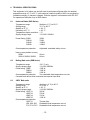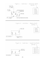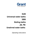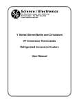
1
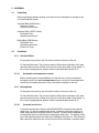
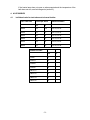
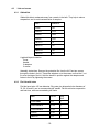
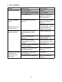
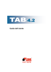
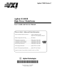
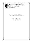
Science / Electronics
521 Kiser Street Dayton, Ohio 45404-1641
(937) 224-4444 Fax: (937) 224-4434
E-mail: sales@se-one.com
Universal Baths - SUB Series
Unstirred Baths - JB/PY Series
Boiling Baths - SBB Series
User Manual
User Manual for Unstirred Baths, Universal Baths, and Boiling Baths
Universal Baths
SUB6
6 liter
SUB14
14 liter
SUB28
28 liter
SUB36
36 Liter
Unstirred Baths
JB1/PY1
3.5 liter
JB2/PY2
10 liter
JB4/PY4
16 liter
JB5/PY5
24 liter
Boiling Baths
September 16, 1998
SBB6
6 liter
SBB14
14 liter
SBB28
28 liter
-2-
CONTENTS
Page
1. SAFETY . . . . . . . . . . . . . . . . . . . . . . . . . . . . . . . . . . . . . . . . . . . . . . . . . . . . . . . . . . . . . . . 4
2. ASSEMBLY . . . . . . . . . . . . . . . . . . . . . . . . . . . . . . . . . . . . . . . . . . . . . . . . . . . . . . . . . . . . 6
2.1
Unpacking . . . . . . . . . . . . . . . . . . . . . . . . . . . . . . . . . . . . . . . . . . . . . . . . . . . . . . . . . . 6
2.2
Installation . . . . . . . . . . . . . . . . . . . . . . . . . . . . . . . . . . . . . . . . . . . . . . . . . . . . . . . . . . 6
3. OPERATION . . . . . . . . . . . . . . . . . . . . . . . . . . . . . . . . . . . . . . . . . . . . . . . . . . . . . . . . . . . . 7
3.1
Universal Baths (Models SUB6, SUB14, SUB28, SUB36) . . . . . . . . . . . . . . . . . . . . . 7
3.2
Boiling Baths (Models SBB6, SBB14, SBB28) . . . . . . . . . . . . . . . . . . . . . . . . . . . . . . 8
3.3
Unstirred Baths (Models JB1/PY1, JB2/PY2, JB4/PY4, JB5/PY5) . . . . . . . . . . . . . . 8
4. ACCESSORIES . . . . . . . . . . . . . . . . . . . . . . . . . . . . . . . . . . . . . . . . . . . . . . . . . . . . . . . . . 9
4.1
Individual racks for test tubes and universal bottles . . . . . . . . . . . . . . . . . . . . . . . . 9
4.2
Lids and covers . . . . . . . . . . . . . . . . . . . . . . . . . . . . . . . . . . . . . . . . . . . . . . . . . . . . . 10
4.3
Polypropylene spheres (PS20) . . . . . . . . . . . . . . . . . . . . . . . . . . . . . . . . . . . . . . . . . 11
4.4
Raised shelves for Universal and Boiling Baths . . . . . . . . . . . . . . . . . . . . . . . . . . . 11
4.5
Siphon SYI
. . . . . . . . . . . . . . . . . . . . . . . . . . . . . . . . . . . . . . . . . . . . . . . . . . . . . . . . 11
5. FAULT DIAGNOSIS . . . . . . . . . . . . . . . . . . . . . . . . . . . . . . . . . . . . . . . . . . . . . . . . . . . . . 12
6. TECHNICAL SPECIFICATIONS . . . . . . . . . . . . . . . . . . . . . . . . . . . . . . . . . . . . . . . . . . . . 13
6.1
Universal Baths (SUB Series) . . . . . . . . . . . . . . . . . . . . . . . . . . . . . . . . . . . . . . . . . . 13
6.2
Boiling Bath units (SBB Series) . . . . . . . . . . . . . . . . . . . . . . . . . . . . . . . . . . . . . . . . 13
6.3
JB/PY Bath units . . . . . . . . . . . . . . . . . . . . . . . . . . . . . . . . . . . . . . . . . . . . . . . . . . . . 13
7. MAINTENANCE AND SERVICE . . . . . . . . . . . . . . . . . . . . . . . . . . . . . . . . . . . . . . . . . . . . 14
7.1
Cleaning . . . . . . . . . . . . . . . . . . . . . . . . . . . . . . . . . . . . . . . . . . . . . . . . . . . . . . . . . . . 14
7.2
Replacement of Fuses . . . . . . . . . . . . . . . . . . . . . . . . . . . . . . . . . . . . . . . . . . . . . . . 14
7.3
Resetting the overtemperature cut-out . . . . . . . . . . . . . . . . . . . . . . . . . . . . . . . . . . 15
8. WARRANTY . . . . . . . . . . . . . . . . . . . . . . . . . . . . . . . . . . . . . . . . . . . . . . . . . . . . . . . . . . . 15
9. SERVICE . . . . . . . . . . . . . . . . . . . . . . . . . . . . . . . . . . . . . . . . . . . . . . . . . . . . . . . . . . . . . 15
-3-
1. SAFETY
The following symbols marked on the equipment mean:
Caution:
‚ Caution:
Read these operating instructions fully before use and pay particular
attention to sections containing this symbol
Surfaces can become hot during use.
‚ Always observe the following safety precautions:
Use only as specified by the operating instructions or the intrinsic protection may be
impaired.
‚ After transport or storage in humid conditions, dry out the unit before connecting it to
the supply voltage. During drying out the intrinsic protection may be impaired.
‚ Connect only to a power supply with a voltage corresponding to that on the serial
number label.
‚ Connect only to a power supply which provides a safety ground terminal.
‚ Before moving, disconnect at the power supply socket. Do not remove the plug.
‚ Do not check the temperature by touch, use the temperature display or a thermometer.
‚ To reduce the risk of eye injury during high temperature operation, use safety goggles
or spectacles.
‚ Do not touch surfaces which become hot during high temperature operation.
‚ Ensure that the operating temperature is less than the maximum operating temperature
of your sample material.
Set the adjustable overtemperature cut-out (where applicable) after setting or changing
the set temperature, and reset it at monthly intervals to check that the cut-out is
operating correctly.
‚ Ensure that the power switch is easily accessible during use.
‚ Do not block or restrict ventilation slots.
‚ These baths are for use only with water.
‚ If liquid is spilled inside the unit, disconnect it from the power supply and have it
checked by a competent person.
‚ It is the user's responsibility to carry out appropriate decontamination if hazardous
material is spilled on or inside the equipment.
‚ Do not connect to a power supply or switch on before filling the tank.
-4-
‚ Take care when topping up or draining, as the liquid in the tank may be very hot or
cold.
‚ If the alarm lamp is illuminated do not touch the liquid or the heater, they may be very
hot. Refill carefully, a hot heater can cause a spattering of very hot water droplets and
scalding steam.
‚ Always use a lid or polypropylene spheres when operating above 60 °C. Take care
when raising and removing the lid, it may be hot. Steam and hot vapors can cause
scalding.
‚ Drain before moving the bath. Before draining allow the liquid to cool to below 50 °C or
heat to above 10 °C.
-5-
2. ASSEMBLY
2.1
Unpacking
Remove packing materials carefully, and retain for future shipment or storage of the
unit. Packs should contain:
Universal Bath (SUB Series)
Power Line Cord
Operating Instructions
Unstirred Bath (JB/PY Series)
Perforated Tray
Operating instructions
Boiling Bath (SBB Series)
Perforated Tray
Operating Instructions
Power Line Cord
2.2
Installation
2.2.1
Universal Baths
Fit the power line cord into the A/C power socket on the rear of the unit.
Fill the bath with water. The minimum depth is 50mm above the base of the tank
and the maximum level is 30mm from top of the tank when bath is fully loaded. A
lid or layer of polypropylene spheres must be used with baths above 60 °C.
2.2.1.1
Adjustable overtemperature cut-out
Before switching the Universal Baths on for the first time, using a screwdriver
through the hole in the set overtemperature knob, turn the set overtemperature
control fully clockwise and press. Plug in and switch on power to the unit.
2.2.2
Boiling Baths
Fit the power line cord into the A/C power socket on the rear of the unit.
Fill the bath with water. The minimum depth is 50mm above the base of the tank
and the maximum level is 30mm from top of the tank when bath is fully loaded. A
lid or layer of polypropylene spheres must be used with baths above 60 °C.
2.2.2.1
Constant level device
A constant level device is fitted to the BOILING BATH to maintain the required
water level. To use the constant level device, connect the inlet pipe (black) to a
water supply and the outlet pipe (white) to a drain. The level can be adjusted by
loosening the white nut and raising or lowering the white tube. The position of the
top of the tube determines the water level. Retighten the white nut. After filling the
bath, adjust the water flow rate to the minimum which maintains a constant water
-6-
level when the water is boiling. If connecting to a mains water supply, check that
local water supply regulations are complied with.
Plug in and switch on power to the unit.
2.2.3
Unstirred Baths
Fill the bath with water. The minimum level is 10mm above the top of the perforated
tray and the maximum level is 40 mm from the top when bath is fully loaded. A lid or
layer of polypropylene spheres must be used with baths above 60 °C. Plug in and
switch on power to the unit.
3. OPERATION
3.1
Universal Baths (Models SUB6, SUB14, SUB28, SUB36)
3.1.1
Controls and Indicator lamps (see figure 1)
The temperature display normally shows the water temperature in degrees Celsius.
The set temperature °C (blue knob) sets the required operating temperature.
The display set temperature °C (gray button) shows set temperature when
pressed.
The heater lamp (orange) indicates when the heater is on.
The heater lamp is on continuously while the water is heating up. As the required
temperature is approached, it starts to flash. When the unit is controlling at set
temperature, the heater lamp flashes intermittently.
Alarm lamp (red) illuminates when the overtemperature cut-out has operated
The set overtemperature control sets the operating point of the overtemperature
cut-out.
The cut-out operates if the bath temperature rises above the temperature at which
the cut-out is set. When it has operated, the red alarm lamp illuminates and the
heater is switched off. The temperature continues to be displayed to warn of
possible high temperatures.
3.1.2
Setting the temperature
The display normally shows the water temperature. To show the set temperature at
any time press the gray display set °C button. To set the required operating
temperature, push the gray display set °C button, while turning the blue set
temperature °C knob until the required temperature is indicated on the display.
3.1.3
Setting the overtemperature cut-out
-7-
To protect both the unit and your samples, the overtemperature cut-out should be
set each time the required operating temperature is changed. Using a screwdriver,
adjustment is via the hole in the blue push to reset knob. Turn the cut-out fully
clockwise, and press the blue knob to reset. The cutout is now set at its maximum.
Allow the bath to stabilize at the required operating temperature. Turn the cut-out
slowly counter clockwise using the screwdriver until the red alarm lamp comes on.
Press the outer knob to reset and slowly turn the cut-out clockwise until the alarm
lamp goes out. Turn the cut-out counter clockwise three quarters of the way back
toward the point where the alarm lamp came on. The overtemperature cut-out is
now set approximately 10 °C above the required operating temperature.
Note: If the required operating temperature is above 95 °C turn the control fully
clockwise
3.1.4
Resetting the overtemperature cut-out
If the overtemperature cut-out has operated, the bath needs to cool to below the set
temperature before the cut-out can be reset. Reset by pushing the blue outer knob.
3.2
Boiling Baths (Models SBB6, SBB14, SBB28)
3.2.1
Controls and Indicator lamps (see figure 2)
The set heater power knob controls the power of the heater through an energy
regulator. It Is not a thermostat
For heat up, turn the set heater power knob to maximum. Once the water is boiling,
turn the knob to the minimum position which will maintain boiling.
The heater lamp (orange) indicates when the heater is on
3.2.2
Overtemperature protector
Two fixed overtemperature cut-outs prevent the heater from reaching a high
temperature in the case of low liquid level.
The reset buttons for the cut-outs are on the rear panel.
3.3
Unstirred Baths (Models JB1/PY1, JB2/PY2, JB4/PY4, JB5/PY5)
3.3.1
Controls and indicator lamps (see figure 3)
The power lamp indicates when the unit is plugged into the power supply and is on.
The set temperature knob sets the required operating temperature.
The heater lamp (orange) indicates when the heater is on.
3.3.2
Over temperature protection
The JB1/PY1 unit is protected against overtemperature by an internal thermal fuse.
The larger Unstirred Baths are protected by a fixed overtemperature cut-out.
-8-
If the heater lamp does not come on when expected and the temperature of the
bath does not rise, see fault diagnosis (section 5).
4. ACCESSORIES
4.1
Individual racks for test tubes and universal bottles
Test Tube Size
Tubes per Rack
Model Numbers
J2
J3
10mm
84
102
J2-10; J3-10
13mm
55
70
J2-13; J3-13
16mm
36
44
J2-16; J3-16
19mm
32
40
J2-19; J3-19
25mm
18
24
J2-25; J3-25
30mm
12
20
J2-30; J3-30
Racks Per Bath
J2
J3
SUB6
1
--
SUB14
2
2
SUB28
4
4
SUB36
6
6
JB1/PY1
1
1
JB2/PY2
4
2
JB4/PY4
3
2
JB5/PY5
4
4
-9-
4.2
Lids and covers
4.2.1
Gabled lids
Gabled lids direct condensate away from vessels in the bath. They help to reduce
evaporation, and to avoid contamination of samples.
Bath
Gabled lid
SUB6
LU6
SUB14
LU14
SUB28
LU28
SUB36
LU36
JB1/PY1
LJI
JB2/PY2
LJ2
JB4/PY4
LJ4
JB5/PY5
LJ5
A gabled lid pack contains:
Cover
Handle
2 adapters
2 screws
Assembly instructions: Remove the protective film from the lid. Pass two screws
through the holes in the lid. Thread the adapters on to the screws, so that the 'v' cut
fits over the ridge of the lid. Hold the handle in position against the adapters and
fasten to the lid by tightening the screws.
4.2.2
Flat lids with holes
Flat lids have holes 105 mm diameter. Ring sets give alternative hole diameters of
78, 59, 43 and 31 mm to accommodate tall vessels. Flat lids minimize evaporation
and heat loss, while accommodating tall flasks.
Bath
Flat lid
Ring
Sets
SUB6/SBB6
LF6
2
SUB14/SBB14
LF14
4
SUB28/SBB28
LF28
6
SUB36
LF36
8
JB2/PY2
LF2
6
- 10 -
A flat lid pack contains:
Cover
Set of Rings
4.3
Polypropylene spheres (PS20)
Polypropylene spheres are an alternative to a lid; they minimize evaporation and heat
loss, allow easy access to vessels in the bath, and they are particularly useful for tall
vessels. One package contains approximately 300 spheres.
4.4
Bath
Spheres
required
SUB6/SBB6
1 x PS20
SUB14/SBB14
1 x PS20
SUB28/SBB28
2 x PS20
SUB36
3 x PS20
JB1/PY1
1 x PS20
JB2/PY2
1 x PS20
JB4/PY4
1 x PS20
JB5/PY5
2 x PS20
Raised shelves for Universal and Boiling Baths
Raised shelves alter the effective liquid depth of half the bath to accommodate different
shapes and sizes of vessel simultaneously. Each shelf provides two alternative depths.
You can use more than one shelf per bath to achieve a range of depths. The raised
shelves can be used either side up in the bath to give different liquid depths. The liquid
depth can be set by changing the amount of liquid in the bath
RS14H covers half the area of SUB14/SBB14
RS28H covers half the area of SUB28/SBB28
RS36H covers half the area of SUB36
4.5
Siphon SYI
Use for draining baths.
- 11 -
5. FAULT DIAGNOSIS
Symptom
Possible Cause
Action required
Unit does not operate
Unit not switched on
Switch on
Unit not plugged into power supply
Plug in, switch on
Power supply failure
Check that other electrical
appliances on the same
circuit are working
Over temperature cut-out has
operated
Reset cut-out and check its
setting as described in 3.1.3
and 3.1.4.
Universal Bath alarm
lamp on
or
Check water level. If the cutout operates again or cannot
be reset, have the unit
checked by a technician
SBB Bath heater lamp
does not come on
Temperature does not
rise when expected
Temperature continues
to rise when not
expected (not SBB
boiling bath)
Set temperature is lower than
liquid temperature (not SUB
Baths)
Check set temperature
JB1/PY1 thermal fuse has
operated
Have fuse replaced by
competent person
JB2/PY2,JB4/PY4,JB5/PY5
overtemperature cut-out has
operated
Check water level. Have
cut-out reset by a technician.
See section 7.2.2
SBB boiling bath over temperature
cut-out has operated
Reset cut-outs
Temperature control circuit fault
(not SBB boiling baths)
Have unit checked by a
technician
Set temperature is higher than
water temperature
Check setting
Temperature control circuit fault
Have unit checked by a
technician
- 12 -
6. TECHNICAL SPECIFICATIONS
This equipment is for indoor use and will meet its performance figures within the ambient
temperature range 10° C to 35 °C, with maximum relative humidity of 80% non-condensing.
Installation category II (transient voltages). Pollution degree 2 in accordance with IEC 664.
For operation at altitudes of up to 2000 meters.
6.1
6.2
Universal Baths (SUB Series)
Temperature range:
Setting range:
Stability at 37 °C:
Uniformity at 37 °C:
Temperature display resolution:
Supply voltage range:
(Ambient +5 °C) to 99 °C
15 °C to 99 °C
± 0.2 °C
± 0.2 °C
1 °C
110-120V: 50/60Hz
Power Rating SUB6
SUB14
SUB28
SUB38
350W
700W
1300W
1300W
Overtemperature protection:
Adjustable, resettable safety cut-out
Heat-up rate (ambient to max)
SUB6
SUB14, SUB28, SUB38
90 min
80 min
Boiling Bath units (SBB Series)
Temperature range:
100 ° C only
Supply voltage range:
110-120V 50/60Hz
Power rating: SBB6
1300 W
SBB14
1350 W
SBB28
1350 W
Overtemperature protection:
Two resettable fixed temperature cut-outs
Constant level device which maintains the required liquid level.
6.3
JB/PY Bath units
Temperature range:
Setting range:
Stability at 37 °C
Supply voltage range:
Power rating: JB1/PY1
JB2/PY2
JB4/PY4
JB5/PY5
Overtemperature protection
JB1/PY1
JB2, JB4, JB5
PY2, PY4, PY5
(Ambient + 5 °C) to 90 °C
20 to 90 °C
± 0.3 °C
110/120V 50/60Hz
300 W
750 W
750 W
1350 W
Thermal fuse
Resettable fixed temperature cut-out
Resettable fixed temperature cut-out
- 13 -
7. MAINTENANCE AND SERVICE
All Science/Electronics laboratory products are designed to comply with IEC1010-1 and
can be flash tested. Some are fitted with radio frequency interference suppressors.
Therefore it is recommended that only a d.c. test be performed.
Universal Baths only (SUB series):
The overtemperature cut-out should be checked periodically by turning the set
overtemperature control counter clockwise until the alarm lamp comes on. The cut-out
should then be reset and set-up (see 3.1.3). If the alarm lamp fails to light with the
knob turned fully counter clockwise the unit should be checked by a technician.
No other routine maintenance is required.
7.1
Cleaning
The outer casings can be cleaned with a damp cloth after disconnection. Do not use
solvents. The immersed parts can be cleaned using proprietary heating element
cleaners. CAUTION: these may be toxic - follow the cleaner manufacturer’s
instructions.
Before using any decontamination or cleaning method not recommended, check with
our Service Department to ensure that the proposed method will not damage the
equipment
7.2
Replacement of Fuses
7.2.1 Universal (SUB Series) and Boiling Bath (SBB Series)
Empty the bath. Disconnect the unit from the power supply. Remove the plug from
the socket in the back of the bath. Press down the fuse drawer catch. Pull out the
fuse drawer. Check and replace with the correct fuses if necessary. The fuses
should be 1.25 x 0.25 inch quick acting, rated: 250V
SUB6
SUB14
SUB28
SUB36
5AF
10AF
15AF
15AF
SBB6
SBB14
SBB28
15AF
15AF
15AF
Push back the drawer, and replace the plug.
- 14 -
7.2.2
Unstirred Baths
The fuse is accessible under the base cover. This should only be replaced by a
technician. The fuses should be 1.25 x 0.25 inch ceramic quick acting, rated: 250V
JB1/PY1
JB2/PY2
JB4/PY4
JB5/PY5
7.3
5AF
10AF
10AF
20AF
Resetting the overtemperature cut-out
On JB2/PY2, JB4/PY4 and JB5/PY5 baths the overtemperature cut-out is accessible
under the base cover. This should only be reset by a competent person.
On the JB1/PY1 the overtemperature cut-out is accessible under the top cover. This
should only be reset by a competent person.
8. WARRANTY
When used in laboratory conditions and according to these operating instructions, these
baths are warranted for THREE YEARS against faulty materials or workmanship.
9. SERVICE
It is necessary that a Returned Material Authorization (RMA) number and form be obtained
before return of any Science/Electronics product for any reason. Contact us for more
information. Please be sure to mark the outside of the returned goods package with this
RMA number to ensure prompt handling.
Science/Electronics
521 Kiser Street
Dayton, OH 45404-1641
Phone (937) 224-4444
Fax: (937) 224-4434
Email: service@se-one.com
- 15 -
- 16 -
- 17 -