1
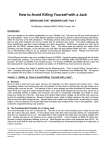
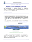
DIGITAL
MICROHMMETER
TYPE DO7
Supplied Accessories: ................................................................................................................ 3
1. SAFETY ................................................................................................................................ 3
WARNING!............................................................................................................... 3
2. INTRODUCTION .................................................................................................................. 4
Display range 6000 .................................................................................................. 4
3. MEASURING PRINCIPLE .................................................................................................... 4
4. CASE DESIGN ..................................................................................................................... 4
5. MAINTENANCE.................................................................................................................... 4
6. BATTERY CHARGING ......................................................................................................... 4
BATTERIES ............................................................................................................. 4
BATTERY REPLACEMENT .................................................................................... 5
7. TECHNICAL DATA ...............................................................................................................5
8. DESCRIPTION OF CONTROLS .......................................................................................... 6
Range Selection:...................................................................................................... 7
Error & Status Lamps .............................................................................................. 7
9. METHODS OF MEASUREMENT......................................................................................... 7
10. POWER UP .......................................................................................................................... 9
11. MEASUREMENT .................................................................................................................. 9
Over-Range ............................................................................................................. 9
12. REMOTE.............................................................................................................................10
13. PRINTER OUTPUT ............................................................................................................10
14. PROTECTION ....................................................................................................................10
15. CALIBRATION PROCESS .................................................................................................11
16. EQUIPMENT REQUIRED ..................................................................................................11
17. PREPARATION ..................................................................................................................11
18. CALIBRATION ....................................................................................................................12
19. VERIFICATION...................................................................................................................12
20. USING DISCRETE RESISTANCE STANDARDS..............................................................13
21. SPECIAL OPERATION - CAL RESET ...............................................................................15
22. AVAILABE ACCESSORIES ...............................................................................................17
CROPICO LTD – DO7
Issue 7/2001
2
IMPORTANT NOTE
Instruments are delivered ready for immediate use; no extras are required.
Supplied Accessories:
1
1
1
Set of test leads
Mains cord
Operating Instructions (English)
When unpacked, inspect for physical damage and report any defects immediately in writing,
retaining packaging materials for inspection. Before placing into service, ensure mains voltage is
correct, instruments are normally supplied for 240V 50Hz. Other voltages may also be selected
according to the chart in section 5, (Maintenance). Be sure to also change the fuse to the correct
type.
1.
SAFETY
This apparatus is designated Safety Class I as defined in the IEC Publication 348
This apparatus has been designed and tested in accordance with IEC Publication 348, entitled
"Safety Requirements for Electronic Measuring Apparatus", and has been supplied in a safe
condition. The present instruction manual contains some information and warnings which must be
followed by the user to ensure safe operation and to retain the apparatus in safe condition.
If this apparatus is to be connected to a fixed installation, then before any other connection is
made, the protective earth terminal must be connected to a protective conductor.
Before switching on the apparatus, make sure that it is set to the voltage of the power supply. The
mains plug shall only be inserted in a socket outlet provided with protective earth contact. The
protective action must not be negated by the use of an extension lead without a protective
conductor.
WARNING!
Any interruption of the protective conductor inside or outside the apparatus, or disconnection of the
protective earth terminal is likely to make the apparatus dangerous. Intentional interruption is
prohibited.
When the apparatus is connected to its mains supply, terminals may be live, and the opening of
covers or removal of parts (except those to which access can be gained by hand) is likely to
expose live parts.
The apparatus must be disconnected from all voltage sources before it is opened for any
adjustment, replacement, maintenance or repair.
Any adjustment, maintenance and repair of the opened apparatus under voltage shall be avoided
as far as possible, and, if inevitable, shall be carried out only by a skilled person who is aware of
the hazard involved.
Make sure that only fuses with the required current rating and of the specified type are used for
replacement. The use of makeshift fuses, and the short-circuiting of fuse holders is prohibited.
Whenever it is likely that the protection has been impaired, the apparatus shall be made
inoperative and be secured against any unintended operation and returned to our factory or Agent
for rectification.
CROPICO LTD – DO7
Issue 7/2001
3
2.
INTRODUCTION
The DO7 is an accurate bench/portable Digital Ohmmeter for the measurement of resistance in the
range 0.1µΩ to 60Ω. It offers you the four terminal resistance measurement method to eliminate
the effect of lead resistance. The measured values are displayed on a 4-digit LCD display; an
overflow of the selected range is also indicated.
Display range 6000
Simple push-button selection of the range required, ensures that the DO7 may be easily used by
unskilled personnel. Error and status warnings are illuminated when appropriate. The utmost care
has been taken to ensure that the ohmmeter will withstand an accidental mains voltage applied to
the measuring terminals, but it is not recommended that voltage should be applied.
3.
MEASURING PRINCIPLE
The measurement is true 4 terminal, using the Kelvin principle. A stable current is produced
across the resistance to be measured via the C terminals, and the voltage drop across the Rx is
measured at the P terminals. This potential drop is then compared against the voltage drop
across internal standards. The ratio of these is then converted to the resistance value of Rx and
displayed in ohms on the digital display. High accuracy and long term stability is achieved by
using our own manufactured internal resistance standards.
4.
CASE DESIGN
The case is ruggedly constructed from an ABS/polycarbonate alloy, coloured safety yellow. A
strong internal sub-frame ensures that the DO7 will withstand the harshest of environments. The
front panel is a reverse printed polycarbonate overlay with clear and unambiguous text.
5.
MAINTENANCE
Normally no maintenance is required other than cleaning with a moist cloth. Avoid aggressive
detergents or solvents.
CAUTION:
Before any maintenance, repair or exchange of parts or fuses, the instrument
must be disconnected from the mains supply and all power sources. In the event
of a fault occurring, the instrument should be returned to our factory or Agent. A
mains fuse is fitted to the mains inlet socket on the front panel, and should be
replaced if necessary.
CAUTION:
Disconnect mains lead and all connecting leads, before removing fuse holder.
Replace only with the correct fuse type, ie. according to the following chart.
Line
Voltage
Selection
Range
VAC
47-63Hz
Fuse (250V)
IEC 127
5 x 20 mm
100V
120V
220V
240V
87-110V
104-132V
191-242V
209-264V
2.5A (T)
1.25A (T)
Maximum Input Power : 80VA
The input circuits are protected by a 6 AMP fuse located in a holder on the main printed circuit
board. Access is gained by removing the top cover. Only replace with the correct fuse type as
below.
10A Am 550V rms HRC Ceramic Cartridge 10 x 38 mm
IEC 269-2-1 NFC63-210
CROPICO LTD – DO7
Issue 7/2001
4
6.
BATTERY CHARGING
The DO7 has built-in rechargeable sealed lead acid batteries which are fully charged when
delivered. To ensure good service life from the batteries, the DO7 incorporates a sophisticated
battery management system. To indicate the state of charge, 8 LEDs indicate the remaining
battery capacity in % of full charge. These LEDs are arranged in a gas gauge style.
The battery charger is built in and the instrument may be connected to 100/120/220 or 240 volts
supply. The appropriate voltage setting must be selected on the inlet socket and the correct fuse
inserted. The LINE LED will illuminate on the front panel to indicate when the mains supply is
connected.
Charging is automatically controlled with built-in protection circuits eliminating the possibility of
over-charging.
The display will blank when the battery voltage is too low to sustain
measurements, and the battery state indicators show the current state of charge. The DO7 will
operate whilst charging on all ranges except the bottom two, and an additional error of
approximately 8 digits may be observed with mains supply connected. The lower ranges have a
larger measuring current than can be supplied by the charger, and therefore batteries must be fully
recharged before use. The batteries will recharge in approximately six hours, and the DO7 lid
should be open to allow for maximum ventilation.
IMPORTANT Always connect instrument to mains supply after use and top up battery.
Instruments should be stored with batteries fully charged, and when stored for long periods
the batteries should be recharged each month.
Should the batteries become deeply discharged due to either being stored with the
instrument switched on, or being left for long periods without charge, then it may appear
that no charging is taking place when first connected to the mains supply. The Line LED
will light but fast charge LEDS will not. The internal charger will automatically sense the
battery state and will trickle charge with a very low current to restore the batteries before
automatically switching to fast charge. This low current charge may take up to 20 hours to
restore the batteries. Continuous charging will not damage the batteries and will, in fact,
keep them in best condition.
BATTERIES
The internal batteries are a sealed lead acid type. Care should be taken when disposing of them
and they may be returned to Cropico for safe disposal.
Any regulations and directions applying to the disposal of such material must be applied.
Do not dispose of battery in fire.
Do not short circuit.
Do not crush, puncture, open, dismantle or otherwise mechanically interfere with the battery.
NOTE: If storing for long periods, the batteries should be fully recharged every six months.
CROPICO LTD – DO7
Issue 7/2001
4
BATTERY REPLACEMENT
Battery replacement should only be carried out by competent and skilled personnel. Care should
be taken to ensure the correct polarity of the connecting wire. The Red Wire always to the positive
battery terminal (Note the blue tag fitted to this wire does NOT indicate polarity). If in doubt please
refer to our Service Department.
7.
TECHNICAL DATA
Digital Display :
4 digit, LCD 0.8" height;
6000 count with automatic
decimal point and error
warning lamps
Working temperature
:
0...+40°C rel.
humidity max. 80%
Normal temperature
:
20°C
Storage temperature
:
-20°C ... +50°C
Mains connection
:
100/120/220/240V
+10 -13% 47-63 Hz
Size (mm.)
:
343 x 327 x 152
Mass
:
8.3 Kgs.
Measurement
Resistance
:
True four-terminal measurement
with fixed dc measuring currents.
Measuring time
:
Approx. 0.5 seconds
Polarity
:
Forward and reverse measurement
current may be selected, plus
average mode which automatically
displays the average value of
positive and negative polarity
measurement.
Ranges and Accuracy
Range
60 Ω
6 Ω
600 mΩ
60 mΩ
6 mΩ
600 µΩ
Resolution
10
1
100
10
1
0.1
mΩ
mΩ
µΩ
µΩ
µΩ
µΩ
Typical
Current
1 mA
10 mA
100 mA
1 Amp
10 Amp
10 Amp
Uncertainty
At 20°C ± 5°C, 1 Year
±(0.15% Rdg + 0.05% FS)
±(0.15% Rdg + 0.05% FS)
±(0.15% Rdg + 0.05% FS)
±(0.15% Rdg + 0.05% FS)
±(0.2% Rdg + 0.1% FS)
±(0.2% Rdg + 0.2% FS)
Temperature
Co-efficient/°C*
40 ppm Rdg
40 ppm Rdg
40 ppm Rdg
40 ppm Rdg
40 ppm Rdg
40 ppm Rdg
+ 30 ppm FS
+ 30 ppm FS
+ 30 ppm FS
+ 30 ppm FS
+ 30 ppm FS
+250 ppm FS
* NOTE Temperature coefficient to be added to uncertainty when operating outside the range 15 to 25°C
NOTE: Measurements on the lowest range 600µΩ will have an additional zero offset of up to 20
digits, if the measuring current is applied for long periods. This offset can be eliminated by using
the average measuring mode.
CROPICO LTD – DO7
Issue 7/2001
5
8.
DESCRIPTION OF CONTROLS
4 Digit LCD Display
Measuring Terminals
Mains Socket
Remote Start Socket
Battery Status Indicator
RS232/Printer Socket
Range Switches
Calibration
CROPICO LTD – DO7
Issue 7/2001
On/Off Power Switch
6
The measuring current polarity may be selected from the front panel. The display will indicate
either + or - to denote the current flow. This is particularly useful when evaluating circuits with
thermal emf or where diode effects can influence the measurement. For measurements where
thermal emf can cause a large measuring zero error, we have provided an additional automatic
average button. When pressed, the measuring current will automatically be reversed and the
average value displayed, thus eliminating the need for external computations. This average facility
will also adjust the measurement time automatically, thus giving the fastest possible measurement
even on inductive circuits.
The +ve and -ve lamps will light to indicate that the current polarity is changing. For very unstable
values where the average mode is unable to establish a stable reading, the averaging will be
aborted after approximately 25 seconds and the display will indicate - - - - A new average cycle will
be automatically initialised.
Range Selection:
The 6 ranges may be selected manually by simply pressing the desired range button. The
selected range will be indicated by an LED and over-range will be indicated by the display reading
- - - -.
Error & Status Lamps
These LEDs will light to indicate the instrument status..
LINE
:
Mains supply is connected to the instrument.
CAL
:
Calibration mode has been initialised by
the key switch and the instrument is in
calibration mode.
O/C
One of the measuring leads is open circuit
LEAD :
(too high resistance), or not connected to
test sample correctly, or the internal protection
fuse is open circuit. The lamp will always
light in standby mode.
9.
METHODS OF MEASUREMENT
9.1 Ohmmeter Connections
The Digital Ohmmeter type DO7 employs a four wire method of measurement, ie. it is necessary to
make four connections to the resistor under test. The instrument is supplied with four leads; two
for the potential connections which are made across the test resistor at the points between which
the resistance is to be determined; and two for the current connections which connects the test
resistor to the supply circuit.
a) Connect the black leads to the C1 and P1 terminals, and the red leads to terminals
C2 and P2.
b) Clip on to the resistor under test (fig. 9-1). Cleanliness is important and if the sample
is not clean, a rub with an abrasive paper to remove oxides is recommended.
c) It is not always possible to use the combined current and potential clips, in which
case test leads with spade tags or special test fixtures may have to be made for the
user to suit particular applications.
d) Fig. 9-2 illustrates connections to various types of test resistors.
e) When measuring 4-terminal resistance standards, do not use the combined current
and potential probes. Make four separate connections to the current and potential
terminals.
CROPICO LTD – DO7
Issue 7/2001
7
Fig. 9.1 Combined current and potential probes
Fig. 9.2 Various types of resistors
CROPICO LTD – DO7
Issue 7/2001
8
10.
POWER UP
When the DO7 is first switched on, a lamp test is automatically performed. All display segments
are illuminated followed by each LED lighting in sequence. NOTE the LOCK LED is not fitted and
will therefore will NOT light. The microprocessor checks for correct internal operation and indicates
"P" if all tests pass O.K. At the same time the software version will be displayed and held for
approximately 2 seconds. The display will typically read "P 1.1". Should the internal checks
indicate an error, then the display will read "HELP". Contact our Service Department or your local
agent for assistance.
The DO7 will perform an automatic zero sequence and finally sets to the following default start-up
mode ready for use. The selected measuring range will be 60Ω, and the DO7 will then be in
stand-by mode.
11.
MEASUREMENT
Connect the resistance to be measured (Rx) to the measuring terminals in accordance with the
diagram on the instrument panel. Select the range required, the measurement mode, ie. +, - or
average. The LED lamp will light to indicate which buttons are active. To initialise the
measurement, press and hold the ON button, the measurement will cease once this button is
released and the instrument will return to the STANDBY state. Should you wish to initialise a
continuous reading, then press the LOCK + ON buttons. The measurement will continue until the
STANDBY button is pressed or the ON button pressed again. An audible BLEEP will sound during
this time to warn the operator that measurement is still in progress, and up to 10 Amps measuring
current is draining the batteries.
DISPLAY HOLD FUNCTION
This works as follows:1. When returning to the STANDBY condition the LAST measured value will remain on
DISPLAY for 30 SECONDS and then blank.
This occurs when:
Pressing the STBY key, or
Releasing the momentary ON key, or
Releasing the momentary external footswitch.
2. Pressing any key (except LOCK) during the 30 second period will force the display to
blank and allow normal operation to resume. It is recommended that the STBY key be
pressed to carry out this function.
Over-Range
The display will indicate - - - -.
Select a higher range.
Open Circuit Lead
O/C LEAD will be displayed and the display will indicate - - - - if the instrument detects that the
lead resistance is too high. The C terminals are checked for compliance voltage. Measurement
should not be made if this warning message is displayed. This warning will also be displayed if the
internal protection fuse is open-circuit. When in STANDBY mode this LED will always be lit.
Connections
When making good quality measurements, it is important to ensure that all measuring leads are in
good condition, and less than 0.2 ohms resistance.
CROPICO LTD – DO7
Issue 7/2001
9
It should also be noted that some spade tags and crocodile clips can produce high thermal emfs
when warmed, particularly nickel-plated brass types. This can cause problems when, for example,
connecting too hot motor windings. The solution is to use plain copper or brass connections
keeping them clean and oxide-free.
12.
REMOTE
If a footswitch or other similar external switch is plugged into the REMOTE socket, it will behave as
an ON key. This feature is particularly useful when used with the PRINT LAST function to enable
"hands free" operation during measurement, with the results printed on an external printer. For
switch connections see page 15.
13.
PRINTER OUTPUT
The print format will be as follows:
SIGN
VALUE
example:
UNIT (measuring mode)
+ 600.0 m ohm (+ve)
- 600.0 m ohm (-ve)
600.0 m ohm (Ave)
The value printed will be followed by a line feed carriage return.
Should the instrument display read over-range then the value will be printed as
---For cable connection details see page 16.
Print All
All measured values will be sent to the printer port (RS232) when "ON". This key toggles ON/OFF.
Print Last
The last measured value only will be sent to the printer port (RS232). This is defined as the last
value measured when switching from "ON" to "STBY". This key toggles ON/OFF.
Baud Rate
This key will display the currently set value when pressed. To change the value, press CLE to
clear and then use the keyboard to enter the new value, finishing with OK. If the new entered value
is a valid rate, then it will be stored and retained in the NVRAM. If it is invalid a long bleep will
sound and it will reset to the last value. The valid Baud Rates are: 75, 110, 150, 300, 600, 1200,
2400, 4800, 9600, 19200. The format is fixed at 8-bit data, 1 start bit, 1 stop bit and no parity.
14.
PROTECTION
Every effort has been made to protect the instrument against voltages being applied to the
terminals. A large 6 Amp fuse is fitted internally to the C measuring line and a gas discharge tube,
GDT, is across the C terminals. If voltages above approximately 90V are applied to the measuring
terminals, the GDT will strike, effectively shorting the C terminals through the 6 Amp protective
fuse, which will interrupt the circuit.
The fuse fitted will interrupt up to 40,000 Amps. The P terminals are not fused and will withstand
up to 460 Volts without damage to the instrument.
WARNING !
To replace the protection fuse, the top instrument panel should be removed, but only after the
mains supply and all input connections are removed. The protection fuse is located on the main
printed circuit board. Only replace with the correct fuse rating.
CROPICO LTD – DO7
Issue 7/2001
10
15.
CALIBRATION PROCESS
This procedure describes the standard calibration method for the DO7 Ohmmeter using Cropico
Calibration Standard Type MTS2. If discrete resistance standards are to be used instead, refer to
section 21 before proceeding.
If the calibration stores are to be pre-set or erased, use the special operation described in section
21 (CAL RESET).
CAUTION
The DO7 will be factory-calibrated to its full accuracy when delivered and any recalibration by the
user will invalidate this initial calibration. The user should therefore be certain that only authorised
and competent personnel are permitted access to the calibration facility, which is key protected.
16.
EQUIPMENT REQUIRED
Cropico Calibration Standard Type MTS2
Set of 2 low thermal emf leads
Set of 2 general purpose leads (10A rating)
Calibration key no. 901
17.
17.1
PREPARATION
Ensure all retaining screws are fitted.
Place unit in temperature controlled environment for a minimum of 4 hours.
batteries are fully charged.
Ensure
17.2
Connect each of the four DO7 terminals to the equivalent terminals on the calibration
Standard. It is essential that low thermal emf leads are used for the P1 and P2 leads (see
Fig.17.1 for the preferred setup).
17.3
The DO7 is powered by internal batteries and these should be fully charged before
carrying out calibration. The mains charger can be left connected, if desired.
17.4
Set the calibration rig to 40 Ohm, Zero.
17.5
Turn the DO7 power ON. If the "HELP" message is displayed, carry out the CAL RESET
operation of section 21 before continuing.
17.6
Leave for a few minutes to stabilise.
CROPICO LTD – DO7
Issue 7/2001
11
18.
CALIBRATION
18.1
Insert the calibration key into the panel switch and turn to CAL. The CAL LED should light
up.
18.2
Set the calibration Standard to 40 Ohm, Zero.
18.3
Set the DO7 to 60 Ohm range, +ve, and press LOCK+ON.
18.4
When the reading has settled, press KYB. The display should read 0.
Press OK. The LED should light up for about 3 sec.
The reading should now be 0.00 +/-1 digit. If not, repeat this step.
18.5
Set the calibration Standard to +FS.
18.6
When the reading has settled, press KYB.
Enter the value 40 using the keypad and press OK. The LED should light up for about 3
sec.
The reading should now be 40.00 +/-1 digit. If not, repeat this step.
18.7
Repeat steps 18.2 thru' 18.6 for the remaining ranges.
18.8
Turn the panel switch to RUN and remove the key.
19.
VERIFICATION
19.1
Ensure that the panel switch is set to RUN and the calibration key is removed.
19.2
Set the calibration rig to 40 Ohm, Zero.
19.3
Set the DO7 to 60 Ohm range, +ve, and press LOCK+ON. Wait for the reading to settle.
The reading should be 0.00 +/-1 digit. Note the actual reading in the Calibration Test
Results sheet.
19.4
Set the calibration rig to +FS and wait for the reading to settle.
The reading should be 40.00 +/-1 digit. Note the actual reading in the Calibration Test
Results sheet.
19.5
Set the DO7 to -ve and wait for the reading to settle.
The reading should be -40.00 +/-1 digit. Note the actual reading in the Calibration Test
Results sheet.
19.6
Set the DO7 to AVE and wait for the reading to settle.
The reading should be 40.00 +/-1 digit. Note the actual reading in the Calibration Test
Results sheet.
19.7
Reset the DO7 to +ve. Set the calibration rig to 4 Ohm, +FS and wait for the reading to
settle.
The reading should be 4.00 +/-1 digit. Note the actual reading in the Calibration Test
Results
CROPICO LTD – DO7
Issue 7/2001
12
19.8
Set the calibration rig to 400m Ohm, +FS and wait for the reading to settle.
The reading should be 0.40 +/-1 digit. Note the actual reading in the Calibration Test
Results sheet.
19.9
Set the calibration rig to 40m Ohm, +FS and wait for the reading to settle.
The reading should be 0.04 +/-1 digit. Note the actual reading in the Calibration Test
Results sheet.
19.10 Repeat steps 5.2 thru' 5.6 for the remaining ranges.
19.11 Turn the DO7 power OFF and remove the test leads.
19.12 Affix a calibration seal label to the instrument.
19.13 Sign and date the Calibration Test Results sheet.
* * END OF NORMAL CALIBRATION PROCEDURE * *
20.
USING DISCRETE RESISTANCE STANDARDS
20.1 Discrete, 4-terminal resistance standards may be used in place of the Cropico Calibration
Standard. The standards must have an uncertainty better than 0.01% if the full calibration
accuracy is to be achieved. Full consideration of the DO7 measuring current must also be
taken into account when selecting the standards. The DO7 can be calibrated to standards
between 1000 and 6000 digits for each range using the KYB entry. However, full accuracy
will only be achieved if standards of 4000 to 6000 digits are used. The following nominal
standards are recommended:
40, 4, 400m, 40m, 4m and 400u Ohm
20.2 In all measurements the P1 and P2 terminals are conventionally connected. Bear in mind
that thermal emfs may be present. The DO7 is particularly sensitive to these on the 600u
Ohm range.
20.3 For FS measurements, connect the C1 and C2 leads in the conventional manner (see Fig
20.1).
20.4 For ZERO measurements, connect the C1 and C2 leads to the C2 terminal of the standard
(see Fig 20.2).
CROPICO LTD – DO7
Issue 7/2001
13
CROPICO LTD – DO7
Issue 7/2001
14
21.
SPECIAL OPERATION - CAL RESET
21.1 This part of the procedure is used to pre-set the calibration memory to a default condition. It
will erase all previous calibration data. With Ver 1.X software, this feature can only be used
if a calibration memory failure has been detected. This test is performed at power-up and
failure is indicated by the HELP message.
21.2 Turn the DO7 power ON. Wait for the display test to complete and the HELP message to
appear.
21.3 Insert the calibration key into the panel switch and turn to CAL. The CAL LED on the front
panel should light up.
21.4 Press CLE. The LED should light up for about 1 sec.
21.5 The HELP message should now be replaced by the normal display.
21.6 Turn the panel switch to RUN and remove the key.
CROPICO LTD – DO7
Issue 7/2001
15
CROPICO LTD – DO7
Issue 7/2001
16
22.
AVAILABLE ACCESSORIES
LEADSETS
HSO1
Duplex Handspikes with 3 metre leads
HSO1-RS
Duplex Handspikes as HSO1 but with remote start button fitted
HSO2
Duplex handspikes with 3 metre and 15 metre leads
HSO2-RS
Duplex Handspikes as HSO2 but with remote start button fitted
LSO3
Large Kelvin clips with 3 metre leads – accept cables and bars up to 38mm
diameter
LSO4
As LSO3 but with 3 metre leads and 15 metre lead lengths
OTHER ACCESSORIES
FSO1
Foot Switch for remote start
PRO1
Portable thermal Printer
CO1
1 Metre Cable Clamp – Wood Base
CO2
1 Metre Cable Clamp – Metal Base
CBO2
Lead Bag attaches to lid
RS101
RS232 Cable
CROPICO LTD – DO7
Issue 7/2001
17
Additional Products From Cropico
DIGITAL OHMMETERS
RESISTANCE BRIDGES
RESISTANCE DECADE BOXES
RESISTANCE STANDARDS
DIGITAL THERMOMETERS
THERMOCOUPLE SIMULATORS
THERMOCOUPLE REFERENCE JUNCTIONS
THERMOCOUPLE SELECTOR SWITCHES
PT100 SIMULATORS
PRECISION WATTMETERS
INSULATION TEST SETS
UNIVERSAL CALIBRATORS
POWER ANALYSERS
HIPOT TESTERS
ELECTRICAL SAFETY TESTERS
Phone, fax or e-mail for further information on the above or for a copy of our
general catalogue:- Phone:- 020 8684 4025
Fax:020 8684 4094
E-mail:- enquiries@cropico.com
Website:- www.cropico.com
CROPICO LTD – DO7
Issue 7/2001
18