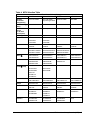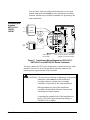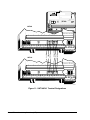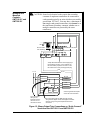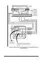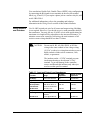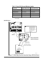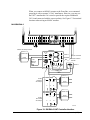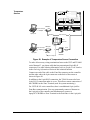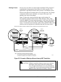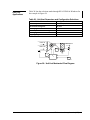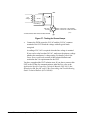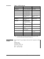
1
Application Specific Controllers Technical Manual 636.3 UNT Controller Section Technical Bulletin Issue Date 0398 Unitary Controller (UNT) Introduction Page 5 • Description 5 • Standards Compliance 6 Configuring the Controller 7 • Using HVAC PRO for Windows Configuration Tool 7 • Defining a UNT Control Device Object • Defining a UNT Control Device in Companion Software *7 9 Installation Procedures 11 • Design Considerations *11 • Tools Needed *11 • Environmental Information • Mounting the Controller *12 • Power Line Wiring Transient Noise Precautions *16 • I/O and Communications Wiring Transient Noise Precautions 12 18 Wiring Details 19 • Power Source and Loads *19 • Wiring Precautions 21 • Grounding and Isolation UNT110/111, 120/121, 140/141 22 • Grounding and Isolation UNT110/111, UNT120/121, and UNT140/141 with Separate Load Transformer *23 * Indicates those sections where changes have occurred since the last printing. © 1998 Johnson Controls, Inc. Code No. LIT-6363081 1 www.johnsoncontrols.com • Terminal Designations • Analog Inputs *30 • Binary Inputs 31 • Binary Outputs (Triac Jumper Information) • Analog Outputs 32 • Zone Bus 32 • Wiring to Unit Mounted Controls--UNT110/111 and UNT120/121 *33 • Wiring to RLY050/002 Relays *35 • Wiring Sensors and Actuators *37 Page 25 *31 Networking the Controller 45 • N2 Bus Overview *45 • Installing the N2 Bus *46 • Zone Bus Communications *48 Application Examples 51 • Fan Coil Applications 51 • Unit Vent Applications *53 • Packaged Rooftop Applications *55 • Heat Pump Applications 57 Downloading/Commissioning 59 • Commissioning Procedures 59 • Via Zone Bus 59 • Via N2 Bus 59 * Indicates those sections where changes have occurred since the last printing. 2 UNT Controller—Unitary Controller (UNT) Troubleshooting Page 61 • Hardware Installation Inspection 61 • Tools Needed for Troubleshooting 61 • Installation Checkout *61 • Troubleshooting the UNT Controller with HVAC PRO for Windows *67 • Troubleshooting the N2 Bus 69 • Zone Bus Troubleshooting--HVAC PRO for Windows 70 Ordering Information 71 • Johnson Controls Code Numbers 71 • Vendor Code Numbers *73 Specifications 77 Appendix A: Precautions for Rooftop Installations 79 • Environmental Information 79 • Installation Requirements *79 • Electrical Noise in Rooftop Units *81 • Nuisance Resets in Rooftop Units *82 • Considerations for Gas Ignition *84 • Considerations for Specific Rooftop Units *88 Appendix B: UNT100/101 91 • What’s Different About the UNT100/101 91 • UNT100/101 Terminal Designations 91 • Grounding and Isolation UNT100/101 93 • Binary Inputs • Binary Outputs *94 94 * Indicates those sections where changes have occurred since the last printing. UNT Controller—Unitary Controller (UNT) 3 4 UNT Controller—Unitary Controller (UNT) Introduction The Unitary Controller (UNT) is an electronic device for digital control of packaged air handling units, unit ventilators, fan coils, heat pumps, and other terminal units serving a single zone or room. It also can be configured as a generic Input/Output (I/O) device for basic point monitoring applications when used within a Metasys® Network. You can easily configure point inputs and outputs, and software features to control a wide variety of Heating, Ventilation, and Air Conditioning (HVAC) equipment applications. The UNT may be used as a standalone controller or connected to the Metasys Network through a Network Control Module (NCM) or Companion. When connected to the Metasys Network, the UNT provides all point control information to the rest of the network. The devices communicate through an N2 Bus. For a smaller facility, the UNT can function as a standalone controller. Figure 1 illustrates the UNT. 5 ANALOG INPUTS BINARY IN 2 BINARY OUTPUT 3 4 5 6 7 8 COMMON 24 VAC 1 COMMON COMMON TO ZONE STAT COMMON ANALOG INPUTS 123456 24VAC COM ZBUS 123456 +15VDC Z BUS COMMON 4 24VAC 3 COMMON 2 24VAC 1 TRACS BINARY INPUT REF N2N2+ +15VDC ANALOG INPUTS 1 2 3 4 5 6 12345678 Description BINARY OUTPUTS DSI unt-110 Figure 1: Unitary Controller (UNT) You may use the UNT for unit ventilator, rooftop, heat pump, or fan coil applications, or as a generic I/O multiplexer and I/O sideloop control. Each has a different sequence of operation, all of which are covered in the HVAC PRO for Windows User’s Manual (FAN 637.5). The Unitary Controller is available in different hardware sets to suit different environmental and application needs. Table 1 lists the common features of the different hardware sets. Table 2 lists the differences by model. UNT Controller—Unitary Controller (UNT) 5 Table 1: Unitary Controller Hardware Characteristics--Similarities Characteristic Description 6 Analog Inputs RTD temperature elements (1000 ohm nickel, platinum, or silicon) Adjustable 0 to 2k ohm setpoint potentiometers 0 to 10 VDC or 0 to 2 VDC transmitters 4 Binary Inputs (4) 24 VAC input only (24 VAC provided) (1) Momentary pushbutton from Zone Sensor for temporary occupancy mode (BI 5) BI 4 may be used as an accumulator input for frequencies less than 2 Hz. N2 Bus Isolated Zone Bus (see Table 2) Removable screw terminal block, Light-Emitting Diode (LED) Indication, 8-pin phone jack on controller 24 VAC Power in Termination Removable screw terminal block N2 Terminations Removable screw terminal block Table 2: Unitary Controller Hardware Characteristics--Differences Characteristic UNT110-1 UNT111-1 UNT120-1 UNT121-1 UNT140-1 UNT141-1 Operating Temperature Rating 0 to 52°C (32 to 125°F) 0 to 52°C (32 to 125°F) -40 to 52°C (-40 to 125°F) -40 to 52°C (-40 to 125°F) 0 to 52°C (32 to 125°F) 0 to 52°C (32 to 125°F) Analog Outputs: None 2 None 2 None 2 8 6 8 6 8 6 Additional 6-pin Phone Jack Additional 6-pin Phone Jack Fixed Screw Terminal Block Fixed Screw Terminal Block UNT140-101 UNT141-101 0 to 10 VDC @ 10 mA Binary Outputs: 24 VAC Triacs @ 0.5A or 0.8A if total power is limited Low or High side common selectable Zone Bus (see Table 1) I/O Terminations Quick Connects (Spade Lugs) Quick Connects (Spade Lugs) Available Premounted in EWC10, with 24 VAC, 50 VA Transformer UNT110-101 UNT111-101 Standards Compliance Quick Connects (Spade Lugs) Quick Connects (Spade Lugs) The UNT complies with the following standards: ● FCC Part 15, Subpart B, Class A ● IEEE 472 ● IEEE 587 Category A ● UL 916, UL 864 6 UNT Controller—Unitary Controller (UNT) Configuring the Controller Using HVAC PRO for Windows Configuration Tool All UNTxxx-1 models require HVAC PRO for Windows. HVAC PRO for Windows also works with previously released UNT models. This software tool configures, commissions, uploads, and downloads the UNT database. Refer to the HVAC PRO for Windows User’s Manual (FAN 637.5) for more information on configuring the UNT. Defining a UNT Control Device Object In a Metasys Network System, enter data into the Attribute menu to define a UNT device object. 1. Go to the Network Map on the Operator Workstation (OWS). 2. Double-click the system name to which the new UNT object is to be added. 3. On the Item menu, click New. 4. Select Type/N2 devices in the Item New dialog box. U N T - Item N ew Type Accumulator Analog data Analog input Analog output digital Analog output setpoint Binary data Binary input Binary output MS data MS input OK MS output Control system DL/LR group LC group PID loop Fire Zone L2 devices N2 devices S2 devices Card Reader CANCEL Hardware system name: Hardware object name: Copy of (System\Object): itemnew Figure 2: Item New Dialog Box Note: The Hardware System and Hardware Object text fields are not used for this object type. 5. Click OK. UNT Controller—Unitary Controller (UNT) 7 6. Highlight UNT in the Add N2 Device dialog box as shown in Figure 3. +DUGZDUH $GG 1 'HYLFH 2. 'HYLFH 7\SH &$1&(/ $+8 ' '&0 '5 '; ,)& /&3 817 n2dvc Figure 3: Add N2 Device Dialog Box 7. Click OK. 8. Complete the attribute fields in the UNT Definition window (see Figure 4). 817 'HILQLWLRQ H e lp I tem E dit V iew A ction G o To A c cessory 7RZHUB , %RRNPDUN )ORRU 6\VWHP 1DPH 2EMHFW 1DPH ([SDQGHG ,' 1& 1DPH +DUGZDUH 1& *UDSKLF 6\PERO 2SHUDWLQJ ,QVWU +DUGZDUH 1 7UXQN 1XPEHU 1 'HYLFH $GGUHVV 3ROO 3ULRULW\ &RPP 'LVDEOHG 1 )ODJV $XWR 'LDORXW 1 windobj Figure 4: UNT Control-Device Object Definition Window Note: Fill in the blank UNT Definition attribute fields as required. Specify an N2 Device Address from 1 to 255. Default values in the remaining attribute fields may be accepted or changed. 8 UNT Controller—Unitary Controller (UNT) Table 3 explains the blank attribute fields. The Operator Workstation User’s Manual (FAN 634) describes the general procedures for entering and modifying data. Table 3: Blank UNT Object Attributes Attribute Description Entry Values . . . Object Name Identifies the object (i.e., UNT1). The object name cannot be duplicated in the system. 1 to 8 alphanumeric characters Expanded ID Further identifies the object (i.e., Garage Level Heater) 0 to 24 alphanumeric characters (optional) 9. On the Item menu, select Save to save the new UNT object and add the object to the NCM database. 10. Upload the NCM to make an archive copy of the new object. Refer to the Operator Workstation User’s Manual (FAN 634), Uploading from the NCM. Defining a UNT Control Device in Companion Software To define a UNT control device in Companion, refer to the Metasys Companion Technical Manual (FAN 628.1). UNT Controller—Unitary Controller (UNT) 9 10 UNT Controller—Unitary Controller (UNT) Installation Procedures Design Considerations Instructions for installing the UNT and its accessories are detailed in this section. The number and types of components (sensors and actuators) used with the UNT will vary according to application. Analyze the proposed installation for logical locations to place these devices and draw an inventory based on that study. Information on available accessory devices is in the Ordering Information section of this technical bulletin. Decide how close the UNT can be to the air handling equipment while still allowing adequate room for installation and maintenance accessibility. Also take into consideration any existing power sources or communication lines. The UNT must be secured to a solid wall and not to any vibrating surface. IMPORTANT: Tools Needed Do not mount the UNT near high voltage or electrically noisy devices. Refer to Appendix A: Precautions for Rooftop Installations. For a typical installation, you need the following: • HVAC PRO for Windows software, current release • IBM® PC-compatible laptop computer • Microsoft® Windows® (3.xx or 95) • AS-CBLPRO-2 (for Zone Bus downloading, uploading, and commissioning) or MM-CVT101-0 (for N2 downloading, uploading, and commissioning) • two screwdrivers (1/8 in. and 1/4 in. flat-blade) • drill • (optional) AS-ZTU100-1 (Zone Terminal unit) Note: The AS-ZTU100-1 supports both AS-UNTxxx-0 and AS-UNTxxx-1 models. The AS-ZTU100-0 supports AS-UNTxxx-0 models only. UNT Controller—Unitary Controller (UNT) 11 Environmental Information The installation site of the UNT must meet the following environmental standards: • The atmosphere must be free of explosive vapors and escaping gases. • The atmosphere must be free of exposure to corrosive chemical or salt vapors that might damage electrical equipment. • For UNT100/101, UNT110/111, and UNT140/141 series controllers, the temperature must be maintained between 0 and 52°C (32 and 125°F) with relative humidity (non-condensing) maintained between 10 and 90 percent. • For UNT120/121 series controllers used with outdoor rooftop applications, the temperature must be maintained between -40 and 52°C (-40 and 125°F) with relative humidity maintained between 10 and 90 percent. Some intermittent condensation is tolerable. This operating temperature range is possible in the UNT120/121 series controllers due to the heater, coated circuit board, and BZ-1000-7 size enclosure. Mounting the Controller Physical Dimensions The UNT is commonly packaged either in an enclosure provided by the installation contractor, or in an AS-ENC100-0 or EN-EWC10-0 enclosure. The UNT140/141-101 and UNT110/111-101 come mounted in an EWC10 enclosure with a 50 VA transformer. The controller requires a flat mounting surface area to match its dimensions. The UNT controller has the following dimensions: • 165 x 163 x 56 mm (6.5 x 6.4 x 2.2 in.) H x W x D without enclosure • 173 x 185 x 119 mm (6.8 x 7.3 x 4.7 in.) H x W x D with the AS-ENC100-0 enclosure • 229 x 406 x 191 mm (9.0 x 16.0 x 7.5 in.) H x W x D with the EWC10 or UNTxxx-101 version Allow enough room to install the enclosure and conduit for wiring terminations to the controller. 12 UNT Controller—Unitary Controller (UNT) Enclosures for Mounting a UNT 120/121 The UNT120/121 low temperature rated controller must be installed in an enclosure as suggested below, unless it is mounted within the enclosed, low voltage electrical compartment of the mechanical unit being controlled. The BZ-1000-7 enclosure is the common package for a UNT120/121 mounted in the air stream or in the mixed air chamber of a mechanical unit. The BZ-1000-7 enclosure is the recommended size for optimum performance of the UNT120/121. Venting the BZ-1000 enclosure (possibly removing unused knockouts), using the AS-ENC100-0 or EN-EWC10-0, or using a larger enclosure is recommended for environments that regularly exceed 32°C (95°F). The UNT120/121 series controller has the following dimensions: Positioning • 165 x 163 x 56 mm (6.5 x 6.4 x 2.2 in.) H x W x D without enclosure • 259 x 249 x 76 mm (10.2 x 9.8 x 3 in.) H x W x D with the BZ-1000-7 enclosure • 229 x 406 x 191 mm (9.0 x 16.0 x 7.5 in.) H x W x D with the EWC10 or UNTxxx-101 version Before installation, position the controller and enclosure on the proposed mounting surface to ensure that the calculated mounting area is correct. Precise distance measurements can be made between controller terminals and sensor/actuator mounting points on the air handling equipment if the equipment is in place. Confirm electrical power source and conduit requirements at this time. Note: You can install a UNT100/101, UNT110/111, or UNT140/141 series controller in a control panel, or in an AS-ENC100-0 or EN-EWC10-0 enclosure. You must enclose the UNT120/121 series controller in a BZ-1000-7 enclosure or another enclosure of comparable dimensions. Mount the UNT in a convenient location using the predrilled mounting holes. The controller must be mounted vertically on a wall or panel where it can be easily wired through the enclosure cover. This also applies to remote location packages. UNT Controller—Unitary Controller (UNT) 13 Do not use this knockout. Otherwise, controller will be in the way of wiring. 1 3 Top / Bottom 4 Side 2 4 UNT 5 UNT Enclosure (Cover) untencl Figure 5: Installing the UNT Controller in ENC100 Enclosure Kit Installing the UNT in a ENC100 Enclosure Kit To install the UNT in an ENC100 enclosure kit (see Figure 5), use the following procedure: 1. Use a flat-blade screwdriver and pliers to remove the necessary wire passage knockouts ①. 2. Position the enclosure firmly against the mounting surface and mount it with the appropriate screws. 3. Secure the UNT ② inside the enclosure kit ③, using the three mounting tabs ④ on the sides of the controller board base. 4. Attach the enclosure cover ⑤ after installing the wiring. 14 UNT Controller—Unitary Controller (UNT) UNTxxx-101 The UNT can be directly mounted into an EWC10 enclosure. You may also purchase the UNT110/111 or UNT140/141 premounted in an EWC10 enclosure with a 24 VAC 50 VA transformer. When the UNT is premounted in an EWC10 enclosure with a 50 VA transformer, the model number will be UNTxxx-101 rather than UNTxxx-1. For instructions on mounting the enclosure to a wall, see the Application Specific Controllers Technical Manual (FAN 636.3), the Accessories tab, the Universal Packaging Module Technical Bulletin (LIT-6363070). Low Voltage Wiring Trough untpwer2 Figure 6: UNT Premounted in EWC10, with 50 VA Transformer (UNTxxx-101) Mounting a UNT in a EWC10 To mount the UNT in the EWC10, use the following procedure: 1. Position the terminals of the UNT toward the low voltage wiring trough located on the left side of the enclosure (see Figure 6). 2. Align the three mounting holes in the base of the controller with the holes in the backbone of the enclosure. On the side with four mounting holes, use the two outside holes for mounting in the EWC. 3. Secure the controller with three No. 8 x 1 in. screws. For best results, use a plastite type thread. A thread forming or sheet metal type thread may also be used. UNT Controller—Unitary Controller (UNT) 15 Power Line Wiring Transient Noise Precautions The standard UNT, when powered by any typical separate isolation transformer or stepdown transformer, operates reliably in an electrical environment defined as Location Category A by the IEEE 587 Standard; that is, when installed more than 30 feet from electrical distribution panels or major bus and feeder systems in industrial plants. IEEE 587 Location Category A power line surge/noise level is specified at 6 kV, 500 A (Normal Mode Ringwave). Surge Levels The UNT exceeds the Category A specification by meeting these surge levels as well: IEEE-587 style Common Mode Pulse 3 kV IEEE-587 style Normal Mode Pulse 1.5 kV IEEE-472 style Common Mode Ringwave 1.5 kV IEEE-472 style Normal Mode Ringwave 500 V When the controller is installed within 9 m (30 ft) of electrical distribution panels or major bus and feeder systems in industrial plants, you must take further precautions to prevent unwanted binary output cycling, resetting, or other possible controller malfunctions. This electrical environment is defined as Location Category B by the IEEE 587 Standard. You can use the following method to prevent electrical noise from adversely affecting the controller: • Connect an MOV (Metal Oxide Varistor) across the UNT supply transformer primary. The MOV must be rated appropriately for the line voltage. Use the list in Table 4 to select the correct MOV sold through your electronics parts distributor. The UNT meets the following power line surge/noise standards when you correctly apply the MOV as described. IEEE-587 IEEE-472 Common Mode Pulse 1.5 kV Normal Mode Pulse 6 kV Normal Mode Ringwave 6 kV Common Mode Ringwave 1.5 kV Normal Mode Ringwave 500 V Note: The 50 VA split bobbin transformer in the EWC15 or -101 model UNT provides additional surge/noise immunity. For more information, refer to Appendix A: Precautions for Rooftop Installations in this technical bulletin. 16 UNT Controller—Unitary Controller (UNT) Table 4: MOV Selection Table 120 VAC Power Transformer Primary Voltage 208 to 240 VAC 277 VAC 347 VAC Minimum Continuous Voltage Rating 130 to 135 VRMS 250 to 280 VRMS Only 250V types listed 300 to 320 VRMS 385 VRMS Minimum Energy Rating 30 Joules 55 Joules 80 Joules 85 Joules Minimum Peak Current (8 x 20 micro second pulse) 4,000 Amperes 4,000 Amperes 4,000 Amperes 4,000 Amperes UL Recognized Required Required Required Required Harris V130LA10A V250LA20A None None V130LA20A* V250LA40A* V130LA20B* V250LA40B* V130K14 V250K14 V300K14 V385K14 V130K20* V250K20* V300K20* V385K20* D6321ZOV131RA15* D6321ZOV251RA90* D6321ZOV301RA105* None D6521ZOV131RA20* D6521ZOV251RA130* D6521ZOV301RA150* Iskra Malda Mallory Marcon Oneida (CKE) D6921ZOV131RA09 D6921ZOV251RA72 D6921ZOV301RA80 VSAC14DK201U VSAC14DK391U VSAC14DK471U VSAC14DK621U VSAC20DK201U* VSAC20DK391U* VSAC20DK471U* VSAC20DK621U* TNR15G211KM TNR15G391KM TNR15G471K None TNR23G201KM* TNR23G391JM* TNR23G471K* TNR23G211KM* TNR23G391KM* OZ130LA10A OZ250LA20A OZ130LA20A* OZ250LA40A* OZ130LA20B* OZ250LA40B* OZ21L471 None OZ21L221 0216NR14-3 0216NR20-4* ERZ-C14DK201U ERZ-C14DK391U ERZ-C14DK471U ERZ-C14DK621U ERZ-C20DK201U* ERZ-C20DK391U* ERZ-C20DK471U* ERZ-C20DK621U* Phillips 2322-595-51316 2322-595-52516 2322-595-53016 2322-595-53816 Siemens S14K130 S14K250 S14K300 S14K385 S20K130* S20K250* S20K300* S20K385* 0216NR14-3 0390NR14-3 0620NR14-3 0620NR14-3 0216NR20-4* 0390NR20-4* 0620NR20-4* 0620NR20-4* 0216NR20DB* 0416NR14-3 None Panasonic Stetron 0416NR20-4* Thomson VE17M00131K VE17M00251K VE17M00301K VD24M00131K VD24M00251K VD24M00301K * Indicates the preferred model if several are listed. UNT Controller—Unitary Controller (UNT) 17 I/O and Communications Wiring Transient Noise Precautions The I/O wiring and N2 Bus must be “clean,” without electrical noise transients from nearby lighting, heavy equipment switching, or inductive loads being driven. For the N2 Bus, the Transient Eliminator, model TE/JC04C12, made by Advanced Protection Technologies (APT) is recommended. Refer to the Metasys Network Technical Manual (FAN 636), the N2 Communications Bus Technical Bulletin (LIT-636018), for more information. 18 UNT Controller—Unitary Controller (UNT) Wiring Details This section details the special precautions and grounding procedures you must observe when installing the UNT. ! WARNING: Possible Equipment Damage or Electrical Shock. To avoid damaging equipment or suffering electrical shock, ensure that all power supplies to the system have been disconnected prior to wiring installation. The Complementary Metal Oxide Semiconductor (CMOS) circuits used in the controller are static sensitive. Use static protection (anti-static) mats and/or grounding straps when working on or near internal circuitry. Power Source and Loads The power transformer used must comply with: • CSA 22.2 No. 205 • NEMA ICS 2, Part 2, 230 The power to each UNT must be limited to 3 amperes or less. However, if you use one low voltage power trunk to power multiple controllers, follow these precautions: • Ensure that polarity is maintained at each 24 VAC connection. • Enclose 24 VAC power trunks with greater than 4 amperes (100 VA) in conduit as required by the National Electric Code (NEC). • Do not share a UNT’s power transformer with a Companion Panel or any other device with a full-wave rectifier in its power supply. (UNTs use “half-wave” rectification. Half-wave circuitry and full-wave circuitry must not share the same transformer.) • Consider all the actual loads as well as the basic load of the controller when determining the system load. Notes: Some local electrical codes require that the secondary common of the stepdown transformer be connected to earth ground (typically on units which are powered by greater than 150 VAC). The M100 draws 20 VA if using common power for the controller and the M100 actuator. It is recommended that each M100 use its own 24 VAC isolation transformer. UNT Controller—Unitary Controller (UNT) 19 IMPORTANT: Any individual binary output (triac) can drive up to 800 mA when you limit the total 24 VAC power draw. You must limit the power draw of a controller and its load to avoid heat dissipation problems. The total 24 VAC power draw of a UNT installed in an ENC100 or similar size box must be limited to a maximum of 40 VA. The total 24 VAC power draw of a UNT mounted in an open air environment must be limited to a maximum of 75 VA. Tables 5 and 6 will assist you in determining the total 24 VAC power draw of your system. Table 5: UNT Power and Load Specifications System Loads Power Draw UNT with Sensors/Transmitters 10 VA (400 mA) 25 VA for UNT120/121 (due to heater) BO Load Relay, Contactor, Solenoid, Incremental Actuator* Maximum allowable load for any individual binary output (triac) is 19 VA** (800 mA at 24 VAC). Refer to specific product documentation. Minimum required load for each binary output (triac) used is 1.2 VA (50 mA at 24 VAC). Relay loads less than 50 mA may cause triac/relay chattering. If necessary, use a 1k ohm, 2 watt resistor across the relay coil. Triac BOs cannot drive loads which use DC currents, such as a device which has a full-wave rectifier. Triacs can drive only AC resistive or inductive loads, i.e., AC relays, contactors, and actuator motors. If the driving of a DC device is required, a pilot relay must be used to isolate the triac. AO Load See Table 6. Actuator Maximum allowable load for each AO is 10 mA @ 10 VDC with a minimum load resistance of 1,000 ohms. Zone Terminal or CBLPRO 1.2 VA (50 mA) * Actuator VA requirements found in Table 6. **With total controller power limited as described previously. 20 UNT Controller—Unitary Controller (UNT) Table 6: Actuator VA Requirements Wiring Precautions Actuator Type VA Requirements EDA-2040 (ATP-2040) Incremental 3 VA VA-7150 2.7 VA VA-7152 4.7 VA VA-7153 Incremental or 0-10 VDC 2.7 VA VA-7200 Proportional 5.5 VA VA-7202 7.5 VA VA-7203 5.5 VA VA-8020 Incremental 4 VA VA-8050 Incremental 6 VA VA-8022 Voltage (0 to 10 VDC) 4 VA VA-8052 Voltage (0 to 10 VDC) 6 VA M120, M140, M150 Non-spring Return 20 VA M110, M130 Spring Return 25 VA M9100 Non-spring Return Voltage (0 to 10 VDC) 7.5 VA M9200 Spring Return Voltage (0 to 10 VDC) 12 VA Follow these precautions when wiring: • Make all wiring connections in accordance with the NEC as well as in accordance with local regulations. • Locate equipment and route the wiring so that signal wiring is a twisted pair, and separated from power wiring as much as possible. • Make all wiring connections to the UNT using only copper conductors. • Daisy chain the N2. The use of “Y” or “T” bus topologies without a repeater installed in the “T” may cause a loss of communications. Do not use wire smaller than 22 AWG. • Do not run N2 Bus, Zone Bus, Analog Input (AI), Binary Input (BI), Analog Output (AO), or Binary Output (BO) wiring in the same conduit or bundle as line voltage wiring (30 VAC or above), or wiring that switches power to highly inductive loads such as contactors, coils, motors, or generators. Notes: Shielded N2 Bus wiring can be run in the same conduit or bundle as 24 VAC power wiring. Zone Bus, AI, AO, and BI wiring can be run in the same bundle or conduit, where convenient. If the binary output wiring is not wired through other switches or contacts, you may also bundle it with the other I/O wiring, where convenient. UNT Controller—Unitary Controller (UNT) 21 You may have either no earth ground connection, or one earth ground connection which must be at the transformer secondary common, whether one or multiple controllers are powered by the same transformer. Grounding and Isolation UNT110/111, 120/121, 140/141 L1 120/24 L2 Power Transformer 70 OK NO! 24 VAC COM ZBUS +15VDC REF N2N2+ To Load +15VDC 24VAC COM ZBUS REF N2- 24 V BO1 N2+ 24VAC BO2 24VAC TRACS COMMON Triac Contactor BO3 COMMON COMMON COMMON COMMON isoxfmr2 Triac Jumper to 24 VAC only Note: UNT110 is shown in illustration. Diagram is for all UNT models. Figure 7: Transformer Wiring Diagram for UNT110/111, UNT120/121, and UNT140/141 Series Controllers You may connect the UNT power transformer secondary directly to earth ground. If you elect to do so, the grounded side must connect to the common power input terminal of the controller. ! CAUTION: You may have a maximum of one single earth ground connection, which must be at the transformer secondary common, whether one or multiple controllers are powered by the same transformer. When grounding one side of the transformer secondary, the grounded side must connect to the common power input terminal. Connecting the grounded side of the transformer to the 24 VAC power input terminal will damage a CBLPRO-1(-0) or laptop. 22 UNT Controller—Unitary Controller (UNT) Power Transformer Isolation 24 VAC to 24 VAC isolation transformers for UNT110/111, UNT120/121, and UNT140/141 series controllers are not mandatory. Load Isolation UNT110/111, UNT120/121, and UNT140/141 series controllers do not require an isolation relay. However, you must connect the jumper wire from the triac terminal to 24 VAC if the contact or coil loads are grounded (via the single earth ground connection at the transformer secondary common; see Figure 7). In this case, all loads are configured for “high side switching” (see Figure 13). For the UNT140/141, you must move the jumper block to the appropriate position rather than use a jumper wire. Grounding and Isolation UNT110/111, UNT120/121, and UNT140/141 with Separate Load Transformer L1 120/24 Optional Earth Ground L2 UNT Power Transformer To UNT COMMON Only L1 120/24 L2 Load Power Transformer 70 24VAC COM ZBUS +15VDC REF N2N2+ +15VDC 24VAC CO M ZBUS REF N2N2+ BO1 To Load 24VAC BO2 24VAC Triac TRACS COMMON COMMON COMMON Contactor COMMON COMMON isoxfmr Shared Triac Node (Discard small wire jumper.) Note: UNT110 is shown in illustration. Diagram is for all UNT models. Figure 8: Transformer Wiring Diagram for UNT110/111, UNT120/121, and UNT140/141 Series Controllers with a Separate Load Transformer ! CAUTION: Equipment damage hazard. When separate transformers are used, it is very important to remove the jumper that otherwise connects the triacs terminal to 24 VAC (high side) or common (low side). This prevents possible controller damage. UNT Controller—Unitary Controller (UNT) 23 A separate load transformer may be necessary because of transformer VA limitations, or may be desirable to completely isolate loads from the UNT digital circuitry for better noise immunity. You may connect the UNT110, UNT120, or UNT140 power transformer secondary directly to earth ground. If you elect to do so, the grounded side must connect to the common input terminal of the controller. ! CAUTION: Equipment damage hazard. You may have a maximum of one single earth ground connection, which must be at the transformer secondary common, whether one or multiple controllers are powered by the same transformer. When grounding one side of the transformer secondary, the grounded side must connect to the common power input terminal. Connecting the grounded side of the transformer to the 24 VAC power input terminal will damage a CBLPRO-1(-0) or laptop. You may connect the separate load power transformer secondary to earth ground as long as doing so is compatible with the equipment being controlled. 24 UNT Controller—Unitary Controller (UNT) Terminal Designations The UNT terminal designations that identify sensor, actuator, and power connection points are illustrated in Figures 10, 11, and 41. Terminal functions are listed in Tables 7, 8, and 42. You may make connections to the UNT by connecting single wires to the individual screw or spade terminals. Note: The N2 terminal connectors on the new UNTxxx-1 series controllers are different from the UNTxxx-0 series. The REF, N2-, and N2+ terminations are arranged in different order (see Figure 9). 24VAC COM ZBUS ZBUS AREF N2+ N2- REF N2N2+ BO1 24 V Triac UNTxxx-0 BO2 BO3 UNTxxx-1 compare Figure 9: N2 Terminal Connector Comparison UNT Controller—Unitary Controller (UNT) 25 26 UNT Controller—Unitary Controller (UNT) ANALOG INPUTS BINARY IN DSI BO 5 BO 6 AO 1 COMMON COMMON AO CM BO 6 BO 7 BO 8 COMMON COMMON COMMON BINARY IN N2+ 2 3 6 7 8 COMMON CO MMON 5 COMMON 4 COMMON Z BUS CO MMON TRACS 24 VAC 24VAC 1 BINARY OUTPUTS AO 2 BO 4 COMMON BO 5 COMMON REF N2- TO ZONE STAT AO CM BO 3 TRIACS BO 4 COM ZBUS 4 BO 2 DSI COMMON 24 VAC 24VAC +1 5VDC 3 BO 3 ANALOG INPUTS 2 TRIACS COMMON BINARY INPUT 24VAC BINARY IN BO 1 ANALOG INPUTS 1 BO 2 1 2 34 5 6 6 24VAC 5 +15VDC 4 BO 1 UNT111 24VAC COM ZBUS REF N2N2+ BI 4 3 24 VAC BI 4 BI 3 24 VAC 2 24 VAC BI 3 BI 2 UNT110 24 VAC BI 1 24 VAC 24 VAC 1 2 34 5 6 24 VAC BI 2 24 VAC BI 1 +15 VDC +15 VDC ANALOG INPUTS REF N2N2+ 24VAC COM ZBUS AI 6 AI CM AI CM AI 6 AI CM AI 5 AI CM AI 4 AI CM AI 3 AI CM AI 2 AI CM AI 1 ANALOG INPUTS +15VDC +15VDC AI 5 AI CM AI CM AI 4 AI CM AI 3 AI CM AI 2 1 1 2 345 67 8 AI CM AI 1 70 BINARY OUTPUT DSI BINARY OUTPUTS BINARY OUTPUTS ANA OUT scrwtrm1 Note: UNT110/111 is shown in illustration. Diagram is for UNT110/111 and UNT120/121. Figure 10: UNT110/111 and UNT120/121 Terminal Designations Table 7: UNT110/111 and UNT120/121 Terminal Identification Terminal Description Terminal Description AI CM Analog Input Common AI 1 Analog Input 1 AI CM Analog Input Common AI 2 Analog Input 2 AI CM Analog Input Common AI 3 Analog Input 3 AI CM Analog Input Common AI 4 Analog Input 4 AI CM Analog Input Common AI 5 Analog Input 5 AI CM Analog Input Common AI 6 Analog Input 6 +15 VDC +15 Volts DC supply +15 VDC +15 Volts DC Supply 24 VAC 24 Volts AC BI 1 Binary Input 1 24 VAC 24 Volts AC BI 2 Binary Input 2 24 VAC 24 Volts AC BI 3 Binary Input 3 24 VAC 24 Volts AC BI 4 Binary Input 4 24 VAC POWER Transformer High Side COMMON Transformer Low Side ZBUS Zone Bus REF N2 Reference N2- N2 Bus - N2+ N2 Bus + 24 VAC 24 Volts AC BO 1 Binary Output 1 24 VAC 24 Volts AC BO 2 Binary Output 2 TRIACS Shared Triac Node BO 3 Binary Output 3 COMMON Common BO 4 Binary Output 4 COMMON Common BO 5 Binary Output 5 COMMON Common BO 6 Binary Output 6 COMMON/AOCM Common/ AO Common BO 7 / AO 1 Binary Output 7 Analog Output 1 COMMON/AOCM Common/ AO Common BO 8 / AO 2 Binary Output 8 Analog Output 2 UNT Controller—Unitary Controller (UNT) 27 1 2 34 5 6 7 8 70 HIGH TRIAC SWITCHING N2+ REF N2- Z BUS COM 24VAC TO ZONE STAT ZBUS LOW TO ZONE STAT 1 2 3 4 5 6 A AI1 COM A AI2 AI3 COM AI4 A +15 24 AI5 COM AI6 VDC BI1 BI2 VAC 24 TR- BI3 VAC BI4 IAC BO1 R TN BO2 BO3 R TN BO4 BO5 R TN BO6 BO7 R TN BO8 1 2 3 4 5 6 UNT140 N BO6 BO7 RTN BO8 A AI 1 COM A AI 2 AI3 C OM AI 4 A +15 TR24 24 BO1 RTN BO2 BO3 RTN BO4 BO5 RTN BO6 BO7 RTN BO8 AI5 C OM AI 6 VDC BI1 BI2 BI 3 BI4 IAC VAC VAC 24 COM Z VAC BUS DSI REF N2 - N2 + Triac Jumper Connector AI1 A COM AI2 AI3 A COM AI4 AI5 A COM AI6 +15 VDC BI1 24 VAC BI2 24 VAC BI3 BI4 TRIAC BO1 RTN BO2 BO3 RTN BO4 BO5 RTN BO6 N BO6 AO1 A AI1 COM A AI2 AI3 COM AI4 A +15 24 AI5 COM AI6 VDC BI1 VAC A COM AI2 AI3 A COM AI4 AI5 A COM AI6 BI3 RTN BO8 A AO2 COM TR24 A BO1 RTN BO2 BO3 RTN BO4 BO5 RTN BO6 AO1 BI4 AO2 VAC IAC COM 24 COM Z VAC BUS DSI AI1 BI2 BO7 BO7 RTN BO8 N2N2+ REF COM UNT141 ZBUS 24 VAC BO6 REF N2 - N2 + Triac Jumper Connector +15 VDC BI1 24 VAC BI2 BI3 24 VAC BI4 TRIAC BO1 RTN BO2 BO3 RTN BO4 BO5 RTN BO6 BO6 AO1 RTN AO2 A AO1 AO2 COM scrtrm2 Figure 11: UNT140/141 Terminal Designations 28 UNT Controller—Unitary Controller (UNT) Table 8: UNT140/141 Terminal Identification * Terminal Description AI1 Analog Input 1 A COM Analog Input Common AI2 Analog Input 2 AI3 Analog Input 3 A COM Analog Input Common AI4 Analog Input 4 AI5 Analog Input 5 A COM Analog Input Common AI6 Analog Input 6 +15 VDC +15 Volts DC Supply BI1 Binary Input 1 24 VAC 24 Volts AC BI2 Binary Input 2 BI3 Binary Input 3 24 VAC 24 Volts AC BI4 Binary Input 4 TRIAC Shared Triacs Node BO1 Binary Output 1 RTN Return (24 VAC or Common)* BO2 Binary Output 2 BO3 Binary Output 3 RTN Return (24 VAC or Common)* BO4 Binary Output 4 BO5 Binary Output 5 RTN Return (24 VAC or Common)* BO6 Binary Output 6 BO7 or AO1 Binary Output 7 or Analog Output 1 RTN or A COM Return (24 VAC or Common)* or Analog Output Common BO8 or AO2 Binary Output 8 or Analog Output 2 24 VAC 24 VAC Power--Transformer High Side COM Common--Transformer Low Side Z Bus Zone Bus REF N2 Reference N2- N2 Bus - N2+ N2 Bus + Depends on triac switching jumper setting: If high, return is “Common.” If low, return is “24 VAC.” UNT Controller—Unitary Controller (UNT) 29 Analog Inputs The six analog input terminals, their power supply, and their common points occupy the lower left corner of the terminal strip. These inputs may be of two types: resistive or voltage. The UNT processes and controls the configured control strategy. It reads the analog inputs through the analog input DIP switches located directly above the analog input terminals. Use these switches and HVAC PRO for Windows to select the type of analog input. Use the T position for all temperature sensors and setpoint potentiometers. Use the V position for all active voltage transmitters. For humidity applications using 3-wire voltage transmitters, such as the HE-6300 Series, use the 15 VDC power supply terminals next to the inputs for AI 6. Table 9 shows each configuration. Table 9: Analog Input Configurations Range Switch Position Voltage (V) 0 to 2 VDC SW1 to Position V and SW2 to Position 2V Voltage (V) 0 to 10 VDC SW1 to Position V and SW2 to Position 10V Resistance / Temperature (T) 1,000 ohm Nickel, Platinum, Silicon, 2k ohm potentiometer SW1 to Position T and SW2 to Position 2V The UNT has two sets of DIP switches. One set is for configuring the analog input points, and the other set is for setting the controller address. Use Table 10 to set analog input DIP switches. Instructions for setting the N2 Address DIP switches are in the Networking the Controller section of this technical bulletin. 1 23 4 5 6 7 8 5 6 BINARY INPUT 1 2 3 TO ZONE STAT 4 BINARY OUTPUT 1 2 3 4 5 6 7 8 COMMON 4 COMMON 3 CO MMON 2 COMMON ANALOG INPUTS 1 +15VDC 70 CO MMON Setting the Analog DIP Switches AI Type 2V 10V T SW2 ANALOG INPUTS BINARY IN 24VAC TRACS N2+ 24VAC REF N2- 24 VAC COM COMMON ZBUS ANALOG INPUTS 1 2 3 4 5 6 24VAC 1 2 3 4 5 6 O 1 2 3 4 5 6 N + 15VD C Z BUS BINARY OUTPUTS DSI O 1 2 3 4 5 6 N aiswtch2 V SW1 ANALOG Analog Input Switches Figure 12: Setting the Analog Input DIP Switches 30 UNT Controller—Unitary Controller (UNT) The AI switches should be factory set with AI 1, 2, and 3 as resistive inputs, and AI 4, 5, and 6 as 0 to 10 VDC inputs. You may reconfigure the switches by using the following table. For example, if you connect a 10 VDC input to AI 4, set SW1-4 to Off and SW2-4 to On. Table 10: Analog Input DIP Switch Settings Hardware Point Switch Binary Inputs Temp (Resistive Input) SW1 SW2 2 VDC (0 to 2 VDC Input) SW1 SW2 10 VDC (0 to 10 VDC Input) SW1 SW2 AI 1 ON OFF OFF OFF OFF ON AI 2 ON OFF OFF OFF OFF ON AI 3 ON OFF OFF OFF OFF ON AI 4 ON OFF OFF OFF OFF ON AI 5 ON OFF OFF OFF OFF ON AI 6 ON OFF OFF OFF OFF ON Four binary inputs on the controller are located in the center of the terminal strip. The binary inputs on the UNT110/111, 120/121, and 140/141 series controllers are inactive when open or connected to UNT common. When a binary device closes to complete a binary circuit, the binary input provides the 24 VAC which, in turn, activates the input. Binary inputs have a threshold between 5 VAC and 18 VAC. BI 4 may be used as an accumulator input for frequencies less than 2 Hz. Binary Outputs (Triac Jumper Information) Binary outputs are triacs on the controller hardware. The controller has either six or eight binary outputs. These outputs switch 24 VAC to the output. For the UNT110/111, UNT120/121, and UNT140/141 series controllers, use the terminal labeled TRIACS when using a separate load transformer. Remove the high side/low side triac jumper on the UNT110/111, UNT120/121, and UNT140/141 for this application (see Figure 8). For important power and load specifications, see Table 5. UNT110/111 and UNT120/121 The terminal labeled TRIACS on the UNT110/111 and UNT120/121 series controllers is the internal shared node of each triac output (see Figure 13). When connecting this terminal (via the wire jumper) to 24 VAC for high side switching, each load must be connected between the binary output terminal and any common terminal. When connecting this terminal to common for low side switching, each load must be connected between the binary output terminal and any 24 VAC terminal. UNT Controller—Unitary Controller (UNT) 31 UNT140/141 On the UNT140/141 series controller, terminals labeled RTN (Return) are associated with the binary outputs, and a jumper block sets high side or low side switching. Setting the jumper block to Low Side BO sets the RTN terminals to 24 VAC. Setting the jumper block to High Side BO sets the RTN terminals to common. Analog Outputs The UNT101, UNT111, UNT121, and UNT141 controllers have two analog outputs. The load connects between the analog output and analog output common terminals. Each output generates a proportional voltage output of 0 to 10 VDC to common. The maximum load for each output is 10 mA with a minimum 1000-ohm load resistance. Zone Bus The Zone Bus provides UNT connections for M100C series actuators, CBLPRO (for HVAC PRO for Windows commissioning), and the Zone Terminal (ZT). The Zone Bus is available for connection at the Zone Temperature Sensor, Zone Humidity Sensor, M100C series actuators, UNT Controller Board, and CBLPRO. 32 UNT Controller—Unitary Controller (UNT) Wiring to Unit Mounted Controls-UNT110/111 and UNT120/121 ! CAUTION: Some local electrical codes require the secondary common of stepdown transformers be connected to earth ground (typically on units which are powered by greater than 150 VAC). You may have a maximum of one single earth ground connection, which must be at the transformer secondary common, whether one or multiple controllers are powered by the same transformer. BINARY OUTPUTS LED Internal Shared Triac Node UNT Controller Triac Switching Internal Wiring Connections 24 COM ZBUS VAC REF N2 - N2+ Jumper allows field selection of the supply leg to be switched by the triacs. In this example, the triacs terminal is jumpered to "24 VAC", so the triacs switch the 24 VAC power (high side) leg. COM L1 L2 24 VAC Unit Mounted Control Enclosure Stepdown Transformer 24 VAC COMMON FAN HEAT COMPRESS Fan Relay Heat Relay Comp. Relay See the Application Examples section for more information. See CAUTION for Wiring to Unit Mounted Controls-UNT110/111 and UNT120/121 section. wireunt1 On unit mounted controls, OEMs typically minimize wiring between digital controls and equipment interface relays by using one leg of the stepdown transformer as common. Figure 13: Binary Output Triac Connections on “Quick Connect” Versions of the UNT110/111 and UNT120/121 UNT Controller—Unitary Controller (UNT) 33 Triac Switching Jumper Internal Wiring Connections 24 COM Z VAC BUS REF N2 - LOW HIGH Jumper allows field selection of the supply leg to be switched by the triacs. In this example, the triacs' BOs will switch to the 24 VAC power (high side) leg. N2 + UNT Controller Triac Switching 24 VAC BI2 BI 3 24 VAC BI 4 TRIAC BO1 RTN BO2 BO3 RTN BO4 BO5 RTN BO6 B04 B02 B01 COM 24 VAC L1 L2 Unit Mounted Control Enclosure Stepdown Transformer 24 VAC COMMON FAN HEAT COMPRESS Fan Relay Heat Relay Comp. Relay wireunt2 See CAUTION for Wiring to Unit Mounted Controls-UNT110/111 and UNT120/121 section. On unit mounted controls, OEMs typically minimize wiring between digital controls and equipment interface relays by using one leg of the stepdown transformer as common. Figure 14: Binary Output Triac Connections on Terminal Strip Versions of the UNT140/141 34 UNT Controller—Unitary Controller (UNT) Connect power to the relay module and the transformer through the conduit knockouts in each box. Wire the module according to the following diagrams. For a schematic diagram of the relay module, see the Application Specific Controllers Technical Manual (FAN 636.3), the AHU Controller tab, the AHU Controller Technical Bulletin (LIT-6363010), the AHU Tower Wiring Details section. ! WARNING: Possible equipment damage or electrical shock. Disconnect power circuit before wiring relay kit. Figure 15 shows a UNT110/111 wired to an RLY050/002 with no BOs isolated from earth ground. BO 8 BO 6 COMMON BO 7 BO 5 COMMON COMMON COMMON BO 4 TRIAC COMMON BO 2 BO 3 24VAC BI 4 24VAC BO 1 BI 3 +15VDC +15VDC 24 VAC AI 6 AI CM BI 2 AI 5 AI CM 24 VAC AI 4 AI CM BI 1 AI 3 AI CM 24 VAC AI 2 AI CM BINARY OUTPUTS BINARY IN 24 VAC AI 1 ANALOG INPUTS AI CM Wiring to RLY050/002 Relays Jumper Low Voltage High Voltage (See Note 1.) Note 3 A COM NC NO A B COILS TRIAC B NC HAND HOA COM COM NO OFF AS-RLY050-0 / AS-RLY002-0 unt1ahu Note 1: Separate low voltage wiring on the left from line voltage wiring on the right. Note 2: Hand operation using the H/O/A switch requires common to the COILS terminal and 24 VAC to the TRIAC terminal to energize the relay. Note 3: The Hand or Off position signals the binary input connected to those terminals. These switches can be hardwire "OR"ed and connected to one BI. This switch uses the HOA COM terminal, which is isolated from the relays. Note 4: Your application will determine exact connections to UNT. Figure 15: UNT110/111 Wired to RLY050/002 UNT Controller—Unitary Controller (UNT) 35 Figure 15 shows a jumper between 24 VAC and the triac. If the jumper is between the triac and common make the following changes: 1. Disconnect TRIAC from HOA COM. 2. Reverse the COILS and TRIAC wires from RLY050 to the UNT. 3. Run a separate wire from HOA COM to 24 VAC at the Binary In terminal section. Figure 16 shows a UNT110/111 wired to an RLY050/002 with all BOs isolated from earth ground. BI 3 BI 4 BO 1 BO 2 BO 3 24 VAC 24 VAC 24VAC 24VAC TRIAC BO 8 BI 2 24 VAC BO 7 BI 1 24 VAC COMMON +15VDC +15VDC COMMON AI 6 AI CM BO 6 AI 5 AI CM BO 5 AI 4 AI CM COMMON AI 3 AI CM COMMON AI 2 COMMON AI 1 AI CM BO 4 BINARY OUTPUTS BINARY IN AI CM ANALOG INPUTS 24 VAC (R) 24 VAC 110 VAC COM (B) Low Voltage High Voltage Note 3 A (See Note 1.) COM NC NO A B COILS B NC TRIAC NO HAND HOA COM COM OFF AS-RLY050-0 / AS-RLY002-0 unt2ahu Note 1: Separate low voltage wiring on the left from line voltage wiring on the right. Note 2: Hand operation using the H/O/A switch requires common to the COILS terminal and 24 VAC to the TRIAC terminal to energize the relay. Note 3: The Hand or Off position signals the binary input connected to those terminals. These switches can be hardwire "OR"ed and connected to one BI. This switch uses the HOA COM terminal, which is isolated from the relays. Note 4: Your application will determine exact connections to UNT. Figure 16: UNT110/111 Wired to RLY050/002 with Isolated BOs 36 UNT Controller—Unitary Controller (UNT) You can obtain a Double-Pole, Double-Throw (DPDT) relay configuration by connecting the BO signal to two terminals on the relay kit terminal block (e.g., B and C). If you require a phone jack at a remote relay kit, add an AS-CBLCON-0. For additional information, refer to the grounding and isolation information in the Wiring Details section of this technical bulletin. Wiring Sensors and Actuators Use 18 AWG twisted pair wire for all sensor and output wiring. Shielding is not required. However, if you decide to use it, earth ground the shield at the transformer. You may also use 24 AWG wire in some applications, but maximum wire length will be reduced due to the increased resistance. To minimize sensor error caused by field wiring, the total resistance of all resistive sensor wiring should be less than 3.0 ohms. ! CAUTION: Do not run AI, BI, AO, BO, ZBUS, or N2 Bus wiring in the same conduit as line voltage wiring (30 VAC or above) or wiring that switches power to highly inductive loads such as contactors, coils, motors, or generators. The insulator on the +15 VDC terminal prevents inadvertent shorting to the adjacent 24 VAC terminal. To prevent damage to the controller, remove and discard this insulator only when you need to use that specific terminal. Table 11: Input and Output Load Impedances Function Range DC Input Impedance Sensor or Load Impedance DC Supply 14.6-17 VDC at 90 mA N/A 162-10M ohm AI Voltage 0-2V or 0-10 VDC 470k ohm 0-5k ohm AI Temperature/ Potentiometer 1000 ohm Si, Ni, Pt, or 0-2k ohm Potentiometer 3540 ohm 0-2k ohm BI VAC 60 Hz 0-24 VAC, 2.5V 470k ohm 0-5k ohm AO Voltage 0-10 VDC @ 10 mA maximum N/A 1k-10M ohm BO VAC Triac 24 VAC @ 50-800 mA* N/A *30-480 ohm Inputs Outputs * With total controller power draw limited as described previously. UNT Controller—Unitary Controller (UNT) 37 Table 12: Sensor Wire Sizes and Maximum Lengths Sensor Type 18 AWG Wire Size Run Length In Meters (Feet) 24 AWG Wire Size Run Length In Meters (Feet) AI Temperature (Resistive) 152.4 m (500 ft) 30.5 m (100 ft) AI Voltage 152.4 m (500 ft) 30.5 m (100 ft) BI Voltage/Contact 152.4 m (500 ft) 152.4 m (500 ft) Single BO at 0.1 A 152.4 m (500 ft) 3.0 m (10 ft) Single BO at 0.5 A 30.5 m (100 ft) 6.1 m (20 ft) Zone Bus 152.4 m (500 ft) 15.2 m (50 ft) Zone Thermostat *30.5 m (100 ft) Eight Conductor Phone Cable *Note: If a CBLPRO-2 and a Zone Terminal are used, the cable length must be limited to 15 m (50 ft). M100/R81CAA-2 12345678 TO ZONE STAT 1 24VAC BINARY INPUT 1 2 3 4 REF N2N2+ ANALOG INPUTS 1 2 3 4 5 6 +15VDC 70 BINARY OUTPUT 2 3 4 5 6 7 CAUTION: If the same transformer is used for both the UNT and M100 boards, ensure that polarity is correct, i.e., COM connected to T1, to avoid shorting the transformer. 8 ANALOG INPUTS BINARY IN COMMON COMMON COMMON 24VAC COMMON 24 VAC TRACS COMMON COMMON ANALOG INPUTS 1 2 3 4 5 6 24VAC COM ZBUS 1 2 3 4 5 6 +15VDC Z BUS BINARY OUTPUTS DSI UNTxxx-1 shown here. COM CW COM T1 COM ZBUS CCW BUS 24 VAC T2 Note: When you connect an M100C actuator to the Zone Bus, we recommend powering it with a separate 24 VAC transformer. M100 Motor with R81CAA-2 Board HVAC PRO for Windows indicates the needed address. Zone Bus Address Switch Set address to 22. O1 2 3 4 5 6 7 8 N untm100c Figure 17: M100C Motor Zone Bus Connection Using an R81CAA-2 Board 38 UNT Controller—Unitary Controller (UNT) When you connect an M100C actuator to the Zone Bus, we recommend powering it with a separate 24 VAC transformer. However, you may use the UNT’s transformer if it is sized to provide the required additional 20 VA and connected with the correct polarity. See Figure 17 for terminal locations when wiring an M100C actuator. M100/R81EAA-2 ANALOG INPUTS BINARY IN Outdoor Air Damper Control BINARY OUTPUTS R81EAA-2 24 VAC 120/24 VAC A T2 S2 Power Transformer C S1 A91 Mixed Air Sensor Temp 8 9 B X B3 B1 COM T1 NC NO 10 BO8 Damper Command COMMON BO7 Minimum Position Override B2 Y45AA-9 C 15,000 ohms M100J for Return Air Damper 10 9 8 X COM 120/24 VAC T1 Power Transformer T2 24 VAC 10 M100J for Exhaust Air Damper 9 8 X COM 120/24 VAC T1 Power Transformer T2 24 VAC untm100e Figure 18: R81EAA-2 UNT Controller Interface UNT Controller—Unitary Controller (UNT) 39 HE-6300 Humidity Sensor Perform the following steps to connect an HE-6300 Humidity Sensor to the UNT (see Figure 19): 1. Set the analog input DIP switches on the AS-UNTxxx board to 10 volts: Switch 1 = OFF Switch 2 = ON 2. Enter the range of the humidity sensor through HVAC PRO for Windows (0 to 10 VDC is equal to 0 to 100% RH). O 1 2 3 4 5 6 N Analog Input DIP Switch Setting SW2 O 1 2 3 4 5 6 N SW1 ANALOG ANALOG INPUTS BINARY IN BINARY OUTPUTS DSI unthe PWR OUT COM HE-6300 Humidity Sensor Figure 19: Example of HE-6300 Humidity Sensor Connection 40 UNT Controller—Unitary Controller (UNT) 12345678 ANALOG INPUTS CBLPRO BINARY IN COMMON 8 COMMON COMMON 24VAC BINARY OUTPUT 2 3 4 5 6 7 TRACS 1 COMMON N2- 24 VAC TO ZONE STAT N2+ COMMON COM ZBUS ANALOG INPUTS 1 2 3 4 5 6 24VAC 1 2 3 4 5 6 +15VDC Z BUS 24VAC BINARY INPUT 1 2 3 4 REF ANALOG INPUTS 1 2 3 4 5 6 +15VDC 70 COMMON Temperature Sensors BINARY OUTPUTS DSI 9-pin or 25-pin Adapter untconn Laptop PC Zone Bus 6-pin to 8-pin or Zone Terminal 6-pin CBLPRO 9-pin or 25-pin Adapter Laptop PC 8-pin to 8-pin or Zone Bus 6-pin to 6-pin Metastat Figure 20: Example of Temperature Sensor Connection To make all necessary wiring terminations between the UNT and TE-6400 series Metastat, use phone cable that has preterminated 8-pin RJ-45 connectors. For cable ordering information, refer to Vendor Code Numbers in the Ordering Information section of this technical bulletin. Connect one end of the cable to the Zone Bus connector on the controller and the other end to the 8-pin connector on the back of the sensor as shown in Figure 20. In addition to the 8-pin RJ-45 connection, the TE-6410 sensor also has a 6-pin, RJ-12 connection under its cover. This allows remote connection of the CBLPRO or the Zone Terminal (used for system monitoring.) For UNT140/141 series controllers, there is an additional 6-pin jack for Zone Bus communication. You may permanently connect a Metastat to the 8-pin jack of the controller and simultaneously connect a laptop PC/CBLPRO or Zone Terminal to the Zone Bus via the 6-pin jack. UNT Controller—Unitary Controller (UNT) 41 Phone Jack Polarization Figure 21 illustrates the polarization of the 6-pin and 8-pin phone jacks on the UNT or Metastat. Terminal 1 is to the extreme left as you face the jack opening, tab notch down. 8-pin 6-pin phonejk Figure 21: Phone Jack Polarization The following table defines the pin usage for each jack. Table 13: Phone Jack Pin Identification 8-Pin Jack (UNT to Temperature Sensor) Pin Signal 6-Pin Jack (UNT140 Controller to CBLPRO or ZT and CBLPRO or ZT to Temperature Sensor) Pin Signal 1 AI 3 Heating Setpoint 1 Not Used 2 AI 2 Warmer/Cooler, or Cooling Setpoint 2 24 VAC 3 AI 1 Temperature Sensor 3 24 VAC/ZnBs Common 4 AI 1 Sensor Common 4 Not Used 5 24 VAC 5 Zone Bus 6 24 VAC / ZnBs Common 6 Not Used 7 AI 2/3 Common 8 Zone Bus Notes: When using the Metastat, do not move the hardware point assignments in HVAC PRO for Windows. For information on cables, refer to the Vendor Code Numbers section in this technical bulletin. 42 UNT Controller—Unitary Controller (UNT) Sharing a Sensor You may use one sensor as a master input to multiple UNTs, instead of mounting and wiring separate Zone Sensors for each controller. This application is especially beneficial when you have a mechanical system that uses more than one terminal unit to serve the same area; for example, a classroom with two unit ventilators, or an open office space with multiple water source heat pumps. Figure 22 shows the wiring and analog input switch settings for two controllers using one Zone Sensor. When sharing a sensor, both controllers must be set to the same temperature sensor type (the default is resistive nickel) on the HVAC PRO for Windows Analog Input Modify screen. To ensure the noise immunity of the UNTs, pull the N2 Bus wiring with the sensor wiring between controllers that share the same sensor. Set the HVAC PRO for Windows software for both controllers for the temperature sensor used. 6 7 8 V ANALOG INPUTS 1 2 3 4 5 6 BINARY INPUT 1 2 3 ANALOG INPUTS BINARY IN BINARY OUTPUTS ANALOG INPUTS DSI 2 BINARY IN N2+ 24VAC 24 VAC REF N 2- COMMON 1 2 3 4 5 6 24VA C ANALOG INPUTS COM 1 2 3 4 5 6 +15VD C TRACS COMMON N2+ REF N2- CO M BINARY OUTPUT 1 3 4 5 6 7 8 Z BUS ZBUS 24 VAC TO ZONE STAT 4 COMMON 5 T RACS 4 COMMON 3 C OMMON 2 C OMMON BINARY OUTPUT 1 C OMMON TO ZONE STAT 4 24VAC COMMON 1 2 3 4 5 6 +15VDC ANALOG INPUTS ZBU S 3 Z BUS 1 2 3 4 5 6 24VAC 2 +15VDC 1 COMMON BINARY INPUT COMMO N 6 COMMON 5 COMMON 4 24VAC 3 70 O 1 2 3 4 5 6 T N 24VA C ANALOG INPUTS +15VD C 70 O 1 2 3 4 5 6 N 1 2 1 2 3 4 5 67 8 T V 10 V 2V Set for 2 VDC and Temperature O 1 2 3 4 5 6 N 12 34 567 8 10 V 2V Set for 2 VDC and Voltage O 1 2 3 4 5 6 N BINARY OUTPUTS DSI Metastat 8-pin Connection on Back N2 + N2 N2 REF Sensor + Sensor - Note: Route sensor wiring and N2 wiring together. Since the UNT Controller is a self-terminating device, end-of-line termination for the N2 Bus is not required. sensor Figure 22: Example of Sharing a Sensor Among UNT Controllers ! CAUTION: Multiple controllers sharing a sensor may only have one single earth ground connection among them. Even if separate transformers are used, only one may be physically tied to earth ground and that connection must be at the transformer secondary common. UNT Controller—Unitary Controller (UNT) 43 Note: If the master Zone Sensor uses the Zone Bus connection, only the master controller can be loaded and commissioned from the sensor connection. The AI offset feature in HVAC PRO for Windows will have to adjust 1°F at the slave AIs to compensate for each additional controller sharing a sensor. 44 UNT Controller—Unitary Controller (UNT) Networking the Controller N2 Bus Overview If you are already familiar with the N2 Bus, go to Installing the N2 Bus. Wiring the Controller to an NCU A hardware connection between the N2 Communications Bus and the Network Control Module (NCM) of the Network Control Unit (NCU) is required if the NCM is to communicate with N2 devices. On the NCM200 and NCM300, the specific connection point for the Metasys Network is the built-in N2 Submodule. On the NCM100 and NCM101/401, install this submodule into one of the submodule slots. N2 Bus Characteristics When installed in a Metasys Network, the UNT receives commands from the NCM or Companion on the N2 Bus, and transmits status reports in return. The maximum electrical limit on the N2 Bus is 255 devices. However, the number of controllers on the N2 Bus is a database memory issue at the NCU or Companion. Refer to the database generation documents in either the Metasys Companion Technical Manual (FAN 628.1) or the Operator Workstation User’s Manual (FAN 634) to determine practical limitations to the number of controllers on the N2 Bus. The N2 Bus connections are electrically isolated from other UNT110/111, UNT120/121, and UNT140/141 circuitry to 500V by optical and magnetic coupling. For runs up to 1,520 m (5,000 ft), use stranded 18 AWG or heavier, twisted 3-conductor wire (electrically, lighter gauge wire works, but it is fragile and prone to nicks and breaks). Avoid using solid wire when possible, as it is prone to break when pulled. Runs longer than 5,000 feet require use of a bus repeater. An N2 network may be extended to a maximum length of 4,568 m (15,000 ft) using two repeaters. The N2 Bus is a daisy chain communications line. It consists of three wires carrying three signals: N2+, N2-, and REF. The N2+ and N2lines carry the data signals. The REF line provides a reference so that each connected device is capable of electrically receiving and transmitting data by creating a common voltage reference among all the devices connected together by the N2 lines. Three lines are required. The configuration of the UNT can be uploaded, downloaded, and commissioned over the N2 Bus using an Operator Workstation (OWS) with HVAC PRO for Windows and an NCM, or a PC with HVAC PRO for Windows and an MM-CVT101-0. This can also be accomplished with Controller Access and Companion directly or remotely connected. Refer to the Controller Access Technical Bulletin (LIT-6364013) in the HVAC PRO for Windows User’s Manual (FAN 637.5). UNT Controller—Unitary Controller (UNT) 45 IMPORTANT: The N2+ and N2- lines must be twisted pair lines. This allows most induced noise (common mode noise) from external sources to affect both lines equally, thereby canceling the noise. Notes: Do not run N2 Bus wiring in the same conduits as line voltage wiring (30 VAC or above) or wiring that switches power to highly inductive loads (such as contactors, coils, motors, or generators). For more N2 Bus overview information, refer to the Application Specific Controllers Technical Manual (FAN 636.3), the Introduction tab, the ASC and N2 Bus Networking and Troubleshooting Guide Technical Bulletin (LIT-6363003). Installing the N2 Bus IMPORTANT: Setting the N2 Address Set the N2 address and test for N2 voltage, polarity, and isolation before actually wiring the UNT for operation. The factory default address is 3. When setting the N2 Address, do not use Address 0. The switches located in the upper right corner of the UNT must be set to the same number as the software assigned to the module. The Metasys (or Companion) Facility Management System (FMS) uses this address for polling and commanding. The numbers are in binary format and horizontally arranged, with the least significant digit on the right. For example, if the controller address is 17 (decimal), the binary representation is 00010001. Switches “1” and “16” must be set to the “on” position (1 + 16 = 17), as shown in Figure 23. 128 64 32 16 8 4 2 1 If you change the address while the UNT is online, you must cycle power for the network to recognize the new address. N O 1 2 3 4 5 6 7 8 1 2 34 5 6 78 ANALOG INPUTS 1 2 3 4 5 6 +15VDC 70 BINARY INPUT 1 2 3 4 TO ZONE STAT 1 BINARY OUTPUT 2 3 4 5 6 7 8 ANALOG INPUTS BINARY IN COMMON COMMON COMMON COMMON 24VAC TRACS COMMON 24 VAC REF N2N2+ COMMON 24VAC ANALOG INPUTS 1 2 34 5 6 24VAC COM ZBUS 1 2 34 5 6 +15VDC Z BUS Address Switches BINARY OUTPUTS DSI d-swtch Figure 23: Setting the N2 Address DIP Switches 46 UNT Controller—Unitary Controller (UNT) N2 Wiring to the Network Control Module 70 ANALOG INPUTS 1 2 3 4 5 6 BINARY INPUT 1 2 3 4 TO ZONE STA T 1 2 BI NA RY OUTPUT 3 4 5 6 7 NCU (TB1 on Communication Terminal Board) HRD 6 3 SFT GRD GRD 5 2 N2SFT GRD 4 1 N2+ REF 8 Z BUS 1 2 34 5 6 ANALOG INPUTS BINARY COM COMMON 1 2 34 5 6 ANALOG INPUTS BINARY IN BINARY OUTPUTS DSI N2 REF N2 N2 + REF N2- N2+ N2 + N2 N2 REF Note: Since the UNT is a self-terminating device, end-of-line termination for the N2 Bus is not required. n2wire-a Figure 24: Connecting the UNT Controller to an NCM Table 14: Terminal Locations TB1 Terminal Function Number UNT Connection Chassis Ground 6 None Soft Ground 5 None N2 Ref 4 REF Soft Ground 3 None N2B - 2 N2 Bus: N2- N2B + 1 N2 Bus: N2+ UNT Controller—Unitary Controller (UNT) 47 N2 Wiring to Companion A hardware connection between the N2 Communications Bus and the Companion PC/Panel/LTD is required to communicate with N2 devices. An MM-CVT101-0 Communications Converter is required to network to the PC Companion. See Figure 25 for terminal locations. Refer to the Metasys Companion Technical Manual (FAN 628.1) for information specific to the MM-CVT101 or Companion Panel/LTD. Companion PC Version 12345678 COMMON ANALOG INPUTS BINARY COM BINARY IN ZBUS ANALOG INPUTS 1 2 3 4 5 6 24VAC COM 1 2 3 4 5 6 TO ZONE STAT BINARY OUTPUT 1 2 3 4 5 6 7 8 24VAC 4 24VAC 3 24VAC 2 24VAC 1 Z BUS 9 VDC BINARY OUTPUTS DSI n2wire-b 9 V COM MM-CVT101-0 BINARY INPUT 24VAC 6 24VAC 5 N2+ 4 24VAC 3 REF N2- 2 24VAC ANALOG INPUTS 1 +15VDC RS232-to-N2 Bus Converter (N2 Bus Terminal) +15VDC 70 REF N2 N2 + N2 REF N2 N2 + N2 + N2 N2 REF To Next N2 Device Figure 25: Connecting the UNT Controller to Companion Note: For more information on installing the N2 Bus, refer to the Application Specific Controllers Technical Manual (FAN 636.3), the Introduction tab, the ASC and N2 Bus Networking and Troubleshooting Guide Technical Bulletin (LIT-6363003). Zone Bus Communications Zone Bus Description The Zone Bus is a 2-wire communications bus that allows a computer to communicate with the UNT, to download the UNT’s database, and to communicate with the Zone Terminals and M100 actuators. A third wire is used for 24 VAC power to the CBLPRO, Zone Terminal, and AS-CBLCON. The bus interface sustains no damage in the presence of fault voltages of 24 VAC or less. M100 actuators should be powered with separate transformers; therefore, only the Zone Bus and common wires need to be pulled. See Table 15 for Zone Bus specifications. 48 UNT Controller—Unitary Controller (UNT) Table 15: Zone Bus Specifications Specification Description Type Multidrop serial communications bus Speed 1200 baud (bits per second) Recommended Cable Type 18 AWG with shield (Beldon 8760) or 24 AWG with no shield (unshielded telephone cord) Maximum Bus Length 150 m (500 ft) with 18 AWG cable or *30 m (100 ft) with 24 AWG cable Range of Addresses 0 to 63 Voltages Logic High-Voltage Logic Low-Voltage Data Transmission *Note: 4 VDC minimum (approximately) 1 VDC maximum (approximately) 1 Start Bit (low level) 8 Data Bits (least significant bit first) 1 Stop Bit (high level) If a CBLPRO-1 and a Zone Terminal are used, the cable length must be limited to 15 m (50 ft). The UNT110/111, UNT120/121, and UNT140/141 series controllers contain an LED that blinks to indicate Zone Bus activity with or without external connection. During power up, there is a brief delay while the UNT undergoes a diagnostic reset. The LED will blink once, turn off for approximately 10 seconds, and turn on again. When a PC communicates with the UNT via CBLPRO, the blink rate may appear to change; that is, it may appear to be more steady. Table 16: Zone Bus LED CBLPRO Description Green LED Cause Off No power to ASC On Zone Bus shorted to common or 24 VAC Blinking Normal Communication The AS-CBLPRO is an interface device used between a computer running HVAC PRO for Windows and Application Specific Controllers (ASCs). It is used for database downloading, uploading, or commissioning via the Zone Bus communication port. When used with a Zone Bus device, such as the UNT or ZT, the CBLPRO is strictly an electrical interface between the serial RS-232 port of the computer and the Zone Bus. CBLPRO operates on 24 VAC drawn from a UNT over the wire used to make the Zone Bus connections. The data transfer rate on both the RS-232 and the Zone Bus is 1200 baud. The connection to the RS-232 COM port of the computer is through a DB9 or DB25 connector supplied with the CBLPRO. After connecting it, make sure the CBLPRO is more than 30 cm (1 ft) away from the computer monitor and system unit. UNT Controller—Unitary Controller (UNT) 49 IMPORTANT: In some cases, a computer monitor or PC will emit electromagnetic noise that may disturb CBLPRO communications. Therefore, do not position the CBLPRO near the monitor or PC. Zone Bus communications to the application specific controllers or ZT may also be monitored with an AS-CBLCON-0. This device has red and green LEDs whose purposes are described in Table 17. Table 17: CBLCON LED Description Red LED Power Green LED Comm Cause Off Off No power to UNT On Off Zone Bus wire open On On Zone Bus wire shorted to common or CBLCON-0 switch in download position On Blinking Normal communications Refer to the Application Specific Controllers Technical Manual (FAN 636.3), the Zone Terminal tab, Zone Terminal Technical Bulletin (LIT-6363014), for proper cabling between the ZT, ASC, and CBLCON. 50 UNT Controller—Unitary Controller (UNT) Application Examples All of the following examples were created by answering configuration questions using HVAC PRO for Windows to identify terminal locations of the inputs and outputs. Refer to the HVAC PRO for Windows User’s Manual (FAN 637.5), the UNT Controller section, for detailed information regarding controller configuration. The UNT110/111 series controller was used in all examples. Fan Coil Applications Table 18: Fan Coil Parameters and Configuration Selections HVAC PRO for Windows Parameters Configuration Selections Heating Type Common Heating/Cooling Coil Lighting Integration Yes Return Air Discharge Air VA1 R1 C1 TE1 FCMECH Figure 26: Fan Coil Mechanical Flow Diagram UNT Controller—Unitary Controller (UNT) 51 120/24 VAC 120 VAC Power Transformer ANALOG INPUTS TE1 RM-T RM-SP 24 VAC BINARY IN BINARY OUTPUTS ANALOG VA1 Fan Relay Triac to Common Jumper IN 1 AC 2 COM 3 IN+ R1 Lighting Relay 24 VAC ON COM OFF fcwire Figure 27: Fan Coil Wiring Example Bill of Materials Table 19: Fan Coil Bill of Materials Component Part Number C1 Digital Controller AS-UNT111-1 TE1 Zone Temperature Sensor TE-6400 Metastat VA1 Valve Actuator VA-8052 Valve Actuator Assembly R1 Lighting Relay GE-RR7 52 UNT Controller—Unitary Controller (UNT) Unit Vent Applications Table 20 lists the selections made through HVAC PRO for Windows for the example in Figure 28. Table 20: Unit Vent Parameters and Configuration Selections HVAC PRO for Windows Parameters Configuration Selections Control Cycle ASHRAE Cycle II Economizer Changeover Dry Bulb Heating Type Proportional Unoccupied Override of Heating Valve Yes Cooling Type None Lighting Integration None Return Air Discharge Air Outdoor Air EP1 TE 3 TE 2 DA 1 C 1 TE 1 uvmech Figure 28: Unit Vent Mechanical Flow Diagram UNT Controller—Unitary Controller (UNT) 53 240/24 VAC 240 VAC Power Transformer ANALOG INPUTS TE1 RM-T RM-SP 24 VAC BINARY OUTPUTS BINARY IN DA1 TE2 T1 T2 COM BUS Triac to 24 VAC BOs High Side Switched ANA OUT + EP1 COM Fan Relay IN COM S 20 TE3 PNEUM uvwire Figure 29: Unit Vent Wiring Example Bill of Materials Table 21: Unit Vent Bill of Materials Component Description Part Number C1 Digital Controller AS-UNT111-1 TE1 Zone Temperature Sensor TE-6400 Series TE2 Outdoor Air Sensor TE-6300 Series TE3 Discharge Air Sensor TE-6300 Series EP1 Electric to Pneumatic Interface EP-8000 Series DA1 Zone Damper Actuator M100CGA-2 54 UNT Controller—Unitary Controller (UNT) Packaged Rooftop Applications Table 22 lists the selections made through HVAC PRO for Windows for the example in Figure 30. Johnson Controls recommends that packaged rooftop applications have separate transformers for controller and loads. Sharing of transformers for controller and loads for packaged rooftop wiring is not recommended. Table 22: Packaged Rooftop Parameters and Configuration Selections HVAC PRO for Windows Parameters Configuration Selections Economizer Output Type Zone Bus Economizer Changeover Type Dry Bulb Heating Type Two Stages Cooling Type Two Stages Outdoor Air Lockout of Heating/Cooling Yes Zone Reset from Humidity No Heating/Cooling Diagnostics Yes Lighting Interface No Air Flow Interlock Yes Exhaust Air '$ Return Air Airflow Switch H T G 1 Outdoor Air H C T L G G 2 1 C L G 2 Discharge Air 6 7( TE 3 C1 TE 1 prmech Figure 30: Packaged Rooftop Mechanical Flow Diagram UNT Controller—Unitary Controller (UNT) 55 R: Equipment 24 VAC B: Equipment Ground G: Indoor Blower W1: Heat-Stage 1 W2: Heat-Stage 2 Y1: Cooling-Stage 1 Y2: Cooling Stage 2 120/24 VAC 120 VAC TE1 Room Sensor 24 VAC Power Transformer BO 7 BO 8 COMMON COMMON Y2 BO 6 BO 5 COMMON BO 4 COMMON BO 3 COMMON TRIAC BO 1 Y1 REF N2N2+ ZBUS 24VAC COM BI 4 24 VAC BI 2 BI 3 24 VAC 24 VAC BI 1 24VAC BO 2 BINARY OUTPUTS BINARY IN 24 VAC AI CM AI 6 AI 4 AI CM AI CM AI 5 AI 3 AI CM AI CM AI 2 AI CM AI 1 ANALOG INPUTS +15VDC +15VDC Triac Jumper Removed TE2 S1 R Y B R B G W1 W2 Unit Terminal Strip TE3 DA1 T1 T2 120/24 VAC COM BUS 120 VAC 24 VAC prtwire2 * * Phase correctly and size the transformer to include 20 VA for the M100C series actuator. Figure 31: Packaged Rooftop Wiring Example with Separate Transformers for Controller and Loads 56 UNT Controller—Unitary Controller (UNT) Bill of Materials Table 23: Packaged Rooftop Bill of Materials Component Part Number C1 Digital Controller AS-UNT110-1 TE1 Zone Temperature Sensor TE-6400 Series TE2 Discharge Air Sensor TE-6300 Series TE3 Outdoor Air Sensor TE-6300 Series S1 Air Flow Switch P32 Series DA1 Damper Actuator M110CGA-2 For more information on rooftop installations, refer to Appendix A: Precautions for Rooftop Installations in this technical bulletin. Heat Pump Applications Table 24 lists the selections made through HVAC PRO for Windows for the example in Figure 32. Table 24: Heat Pump Parameters and Configuration Selections HVAC PRO for Windows Parameters Configuration Selections Heat Pump Type Water to Air Reversing Valve Action On for Heating Supplemental Heat Two Stages Lighting Integration None Return Air COMP1 H T G 1 H T G 2 Discharge Air 5 & 7( hpmech Figure 32: Heat Pump Mechanical Flow Diagram UNT Controller—Unitary Controller (UNT) 57 TE-1 RM-T RM-SP ANALOG INPUTS BINARY OUTPUTS BINARY IN Triac to 24 VAC R: Equipment 24 VAC B: Equipment Ground G: Indoor Blower W: Reversing Valve Y: Compressor W1: Heat-Stage 1 W2: Heat-Stage 2 R B G W (R1) Y W1 W2 Aux1 Aux2 Elect. Heat Unit Terminal Strip 120/24 VAC 120 VAC 24 VAC hpwire Figure 33: Heat Pump and External Transformer Wiring Example Bill of Materials Table 25: Heat Pump Bill of Materials Component Part Number C1 Digital Controller AS-UNT110-1 TE1 Zone Temperature Sensor TE-6400 Series 58 UNT Controller—Unitary Controller (UNT) Downloading/Commissioning Commissioning Procedures Commissioning a UNT begins after the unit is mounted and wired, and the control and hardware/software features have been defined through HVAC PRO for Windows. Refer to the HVAC PRO for Windows User’s Manual (FAN 637.5) for complete controller configuration and commissioning information. A Zone Terminal or laptop PC with HVAC PRO for Windows is recommended to perform a complete system startup procedure. However, these accessories are not required for the basic procedure detailed in this section. Via Zone Bus Downloading and commissioning via the Zone Bus requires using the CBLPRO interface and a laptop or PC running the HVAC PRO for Windows software. You can connect to the Metastat 6-pin connector or directly at the controller. UNT140/141 models have a spare 6-pin connector so that the connection from a Metastat or Zone Sensor would not need to be disconnected during download/commissioning. Communication rate is 1200 baud over the Zone Bus. See Figure 20. Via N2 Bus HVAC PRO for Windows, release 5.00 or higher, allows you to perform downloading and commissioning over the N2 Bus using MM-CVT101-0, Metasys OWS Release 6.0 or higher, or Companion Release 6.00 and Controller Access. Because the communication rate is 9600 baud, performing this process over the N2 Bus saves a great deal of time when loading the initial configuration files and parameters into the controller. UNT Controller—Unitary Controller (UNT) 59 60 UNT Controller—Unitary Controller (UNT) Troubleshooting Hardware Installation Inspection Once the mechanical contractor starts receiving delivery of the UNTs with factory mounted controls, we recommend that arrangements be made to pull a sample of the shipment for bench testing. This can be done by loading a job configuration before all the controllers are mounted in the unit cabinets. Tools Needed for Troubleshooting Tools needed for typical troubleshooting include: • ASC and N2 Bus Networking and Troubleshooting Guide Technical Bulletin (LIT-6363003) • Digital Multimeter (DMM) • 100k ohm resistor • (optional) Double banana plug (see Figure 34; available from a local electronics store or ITT Pomona Stock No. 34F856 or 34F845), 100k ohm 1/4-watt resistor for earth ground voltage tests 100k ohm, 1/4-watt Use double banana plug for all tests that require a 100k ohm resistor placed in parallel with DMM. Steps: 1. Connect 100k ohm resistor under plug's prongs. 2. Insert banana plug into DMM. 3. Connect leads of DMM into banana plug. banana Figure 34: Double Banana Plug Used with 100k ohm Resistor Installation Checkout Review the mounted UNT and compare it with the appropriate illustrations in the Installation Procedures section of this technical bulletin to ensure proper installation. Also refer to the engineering drawings supplied for the individual site. 1. Ensure that the mounting screws holding the subassembly onto the base frame are secure. 2. Ensure that accessory equipment is connected and labeled correctly. 3. Ensure that the controller terminal connections are secure. 4. Ensure that the N2 connections are secure and labeled correctly. 5. Ensure that the UNT switches are appropriately positioned. (Refer to the Wiring Details and Networking the Controller sections of this technical document.) 6. Ensure that there are no unwanted earth ground connections to the controller. UNT Controller—Unitary Controller (UNT) 61 Although a single earth ground connection to the common terminal of UNT110/111, UNT120/121, and UNT140/141 series controllers is allowed, you may not intend to have one. The procedures described in the following directions may be used when no earth ground connections to the UNT are intended or to ensure that there is only one earth ground connection. Isolation and Grounding UNTs without an Earth Ground Connection This section will help you ensure proper isolation within your system. These procedures are not required, but are recommended to reduce installation errors. To ensure proper isolation, test the following: • field device wiring for proper isolation • transformer for isolation and correct polarity termination • connected field devices, transformer, and UNT for proper isolation 62 UNT Controller—Unitary Controller (UNT) Field Device Wiring Isolation-UNTs without an Earth Ground Connection This section assists you in measuring field wiring which will be terminated to the UNT. If you are confident that the field wiring has no earth grounds, you may go to the following section, Power Transformer Isolation--UNTs without an Earth Ground Connection. A field device that is earth grounded may become apparent when you test the entire controller. • Before you terminate the field wires to the UNT, measure the resistance of each wire to earth ground using an LED test circuit (preferred) or a DVM. For the LED test circuit, assemble the test circuit illustrated in Figure 35. Then, connect the circuit from each input to earth ground and then from each output to ground. For the DVM test, connect the DVM from each input to earth ground and then from each output to ground (see Figure 35). If the LED turns On (or you read a value less than 1 Megohm at any input or output), the circuit is improperly isolated. Replace or repair the wiring or the field device; or, for a binary output, add an isolation relay. Repeat the test until the LED does not turn on. If the LED does not turn On (or you read a value greater than 1 Megohm), the circuit may be properly isolated. (It will not be isolated if there are earth grounds that exist at higher voltages.) A value of infinite ohms indicates a completely isolated circuit at approximately zero volts. Connect this wire to the appropriate UNT terminal and check the next wire. Field Device IN/OUT IN/OUT COM or LED Test Circuit (Preferred Method) DVM (+) (-) 9V Battery 10 mA Red 470 ohm 1/4-watt isocirct Figure 35: Testing for an Isolated Circuit UNT Controller—Unitary Controller (UNT) 63 Power Transformer Isolation-UNTs without an Earth Ground Connection This section will assist you in determining if the supply transformer is properly isolated. • Before connecting the transformer to the UNT, connect the input power to the primary leads of the 24 VAC transformer. • Measure the voltage of each secondary transformer lead to earth ground with the DVM in parallel with a 100k ohm 1/4-watt resistor (see Figure 36; if using a double banana plug, insert the plug into the DVM). If you read 5 VAC/VDC or greater, the transformer is earth grounded. You need an isolation transformer in order to isolate the connections from earth ground and protect system components. Wire a separate 24 VAC to 24 VAC isolation transformer (such as the Y65G13) to the UNT. If you read less than 5 VAC/VDC, the circuit is properly isolated. Usually a value less than 0.10 VAC/VDC indicates a completely isolated circuit. Line Voltage 24 VAC 100k ohm 1/4-watt DVM 100k ohm 1/4-watt DVM transfm1 Figure 36: Testing the Transformer • Determine the polarity of the transformer’s leads by using a DVM referenced to earth ground without the 100k ohm resistor (see Figure 36). Connect the transformer’s secondary lead with the higher voltage potential to the 24 VAC terminal on the UNT. Connect the transformer’s secondary lead with the lower potential to the 24 VAC common terminal on the UNT. 64 UNT Controller—Unitary Controller (UNT) Load Isolation-UNTs without an Earth Ground Connection If the field wires are not yet connected (the Field Device Wiring Isolation--UNTs without an Earth Ground Connection section was skipped), disconnect one 24 VAC wire and terminate the field wires. Reconnect the 24 VAC wire. • Connect the leads of the DVM in parallel with the 100k ohm resistor from the DC power supply (+15 VDC) output terminal of the UNT to earth ground (see Figure 37). This tests whether the field devices, the UNT, and the transformer “assembly” are properly isolated. If you read 5 VDC/VAC or greater indicates the circuit is improperly isolated. Follow these steps to correct this: Note: Binary outputs are often the cause of ground loops; therefore, we recommend that you test the binary outputs of the UNT before testing other points. 1. Remove all the field wires and N2 Bus wires from the UNT, but leave the transformer wires attached. 2. With the DVM still connected, reconnect each set of field wires one at a time until you read 5 VDC/VAC or greater. At this point, you have discovered one cause of the ground loop. Correct the problem. If you check all the field wires and you still read greater than 5 VDC/VAC, the transformer secondary is earth grounded. In this case, wire a 24 VAC to 24 VAC isolation transformer to the UNT and measure again. If the value is still 5 VDC/VAC or greater, replace the UNT. 3. Continue to reconnect each set of field wires until all ground loops are found and corrected. You’ll know that all grounds are corrected when you read less than 5 VDC/VAC on the DVM. If you read less than 5 VDC/VAC, the circuit is properly isolated. A value of less than 0.10 VDC/VAC indicates a completely isolated circuit. UNT Controller—Unitary Controller (UNT) 65 UNT 24 VAC Line Voltage 15 VDC 24 VAC 24 VAC COM Field Wiring* 100k ohm 1/4-watt DVM DVM < 5 VDC/VAC = OK (Isolated) DVM > 5 VDC/VAC = Earth Grounded *AICOM, BICOM, ZBUS COM, AOCOM, BOCOM grdloop Figure 37: Testing for Ground Loops • Connect the DVM across the 24 VAC and the 24 VAC common terminal of the UNT. Read the voltage with all typical loads energized. A reading of 24 VAC is required when the line voltage is nominal. If you read a value less than 20 VAC, make sure the primary voltage matches the transformer’s voltage rating. For details, refer to the Power Source and Loads section of this technical bulletin and recalculate the VA requirements for the UNT. You have completed the UNT isolation tests. If you plan to connect this UNT to the N2 Bus for communication to other devices, refer to the Application Specific Controllers Technical Manual (FAN 636.3), the Introduction tab, the ASC and N2 Bus Networking and Troubleshooting Guide Technical Bulletin (LIT-6363003). 66 UNT Controller—Unitary Controller (UNT) Grounding UNT110/111, UNT120/121, and UNT140/141 with an Earth Ground Connection An earth ground connection to the common terminal of the UNT110/111, UNT120/121, and UNT140/141 series controllers is allowed for the 24 VAC power supply and the binary output/triacs (when set up for high side switching). If this earth ground connection exists, it must be at the transformer secondary common terminal only. There should be 0 VAC measured from a common terminal to earth ground and over 20 VAC from a 24 VAC terminal to earth ground, when power is applied. If no earth ground connections were planned for the power supply and/or triacs, and you suspect that an earth ground may exist, use the procedure described above for the UNT100/101 controller to test for the presence of a ground loop condition. ! Troubleshooting the UNT Controller with HVAC PRO for Windows CAUTION: You may have a maximum of one single earth ground connection, which must be at the transformer secondary common, whether one or multiple controllers are powered by the same transformer. Table 26 indicates symptoms and corrections for possible controller malfunctions. We recommend the use of HVAC PRO for Windows Commissioning mode during all troubleshooting procedures. Note: While in the commissioning program, you are actively viewing the controller’s inputs and outputs. The screens will automatically refresh the data values when the controller senses a change in value. UNT Controller—Unitary Controller (UNT) 67 Table 26: Troubleshooting the UNT with HVAC PRO for Windows Symptom Possible Cause Corrective Action Indoor Fan Does Not Run Unit not in Occupied mode. Use the Commissioning mode to force the controller into Occupied mode or insert a jumper across the defined, occupied BI if the UNT is already configured to Occupied mode. Unit does not need heating or cooling. Check the configuration to verify if the fan was to cycle during Occupied mode. Fan off due to air flow loss. Check air proving switch. Restart by breaking and making unit power. Indoor fan not proven. See above. Actuator or linkage Remove actuator cover and check for 24 VAC across T1 and T2. Insert jumper CW to COM. Actuator should fully open outdoor dampers. Remove jumper. Wiring problem Check that wire from Zone Bus on UNT is connected to bus terminal on actuator. Check address of the M100C actuator; it should be 22. Zone Sensor not connected. Ensure Zone Sensor is properly connected with an 8-pin plug to the UNT. Zone temperature not above/below setpoint. Simulate a load at the sensor using HVAC PRO for Windows. Heating or cooling lockout from outdoor temperature. Simulate a value at the OA sensor using HVAC PRO for Windows Commissioning. Delay timers present. Wait until time delays have expired (approximately five minutes). ZT Display Contains Dots Configuration mismatch between the controller and the ZT (a ZTU100-0 is used with a UNTxxx-1 controller). Upgrade the ZTU100-0 to a ZTU100-1. Refer to the Zone Terminal Technical Bulletin in this manual for more information. Binary Output Will Not Turn On or Chatters TRIAC Jumper is not set correctly. Set jumper so that triacs are switching proper side of transformer. Load is not drawing 50 mA (minimum load for triac). Add a 1k ohm, 2-watt resistor across the relay coil. M100C/Zone Bus Economizer Actuator Does Not Open to Minimum Position Heating or Cooling Will Not Turn On Automatically 68 UNT Controller—Unitary Controller (UNT) Troubleshooting the N2 Bus Troubleshoot the N2 Bus if the Companion system is not properly communicating with the UNTs. Tables 26 and 27 cover many UNT or N2 communication problems and suggest which actions to take. Specific troubleshooting tests are also given in this section. Before trying one of these tests, you may be able to determine the cause of the problem by asking yourself the following questions: • Are the N2 Bus wires securely terminated to each UNT? • Is the N2 polarity correct? • Is the UNT powered and ready to respond? • Have you cycled power on a UNT after changing its address? (Refer to Installing the N2 Bus in this technical bulletin). • Are the UNTs configured properly with the correct number of points? ! WARNING: Electrical shock hazard. When troubleshooting, always measure the REF to earth ground voltage with the DMM. If line voltage is measured, have a qualified electrician locate the fault. Table 27: Troubleshooting the N2 Bus Symptom Possible Cause Action N2 Bus is Offline EOL jumpers and/or W3 jumper on MM-CVT101 or Companion Panel/LTD are not installed. Install EOL jumpers and W3 jumper properly. MM-CVT101 is not plugged into PC or 9 VDC source. Plug MM-CVT101 into PC or into a 9 VDC source. N2 Bus polarity is incorrect. Rewire N2 Bus wires for proper polarity. Two or more UNTs have the same address. Change each duplicate UNT address to a unique number. The address of the UNT was changed without its power being cycled afterward. Cycle power on the UNT. The 10-second delay after downloading the UNT has not yet expired (HVAC PRO™ Revision 1.0 or earlier). Wait until the delay expires. Someone is commissioning over the Zone Bus. Wait until the Zone Bus is clear, then try again. UNT Does Not Come Online UNT Controller—Unitary Controller (UNT) 69 Notes: For more N2 Bus troubleshooting information, refer to the Application Specific Controllers Technical Manual (FAN 636.3), the Introduction tab, the ASC and N2 Bus Networking and Troubleshooting Guide Technical Bulletin (LIT-6363003). For NCM troubleshooting information, refer to your NCM technical bulletin. Zone Bus Troubleshooting-HVAC PRO for Windows There are some errors that may occur while using the HVAC PRO for Windows commissioning tool with the UNTs over the Zone Bus. The cause of the error is often a loose or improper connection between the CBLPRO (AS-CBLPRO), laptop PC, and the controller. A defective COM port on the laptop, or a defective controller could also be at fault. Note: It takes ten seconds for a UNT to reset and resume communication after being downloaded. An effective troubleshooting technique is to use a CBLCON and observe its LEDs, which will indicate the problem (see Table 17 for a description of LEDs and their meanings). You may also try exchanging the component that you believe is defective with a working component of the same type. A noisy wire adjacent to the Zone Bus can also cause communication errors. Noise can be periodically induced into the Zone Bus, thereby causing sporadic communication failures between the laptop and the UNT. Most often, noisy lines cause intermittent disruption, not total loss of communication. For more information on HVAC PRO for Windows, refer to the HVAC PRO for Windows User’s Manual (FAN 637.5). 70 UNT Controller—Unitary Controller (UNT) Ordering Information Johnson Controls Code Numbers Controllers Tables 28 - 31 list code numbers and descriptions for the UNTs and accessory equipment. Table 28: UNT Controllers and Accessory Equipment Code Number Description AS-UNT110-1 UNT with eight binary outputs, N2 Isolation, and triac--high or low side selectable AS-UNT111-1 UNT with six binary outputs, two analog outputs, N2 Isolation, and triac--high or low side selectable AS-UNT120-1 UNT110 controller with heater (for low temperature use) AS-UNT121-1 UNT111 controller with heater (for low temperature use) AS-UNT140-1 UNT110 controller with screw terminals for field terminations and spare 6-pin Zone Bus phone jack AS-UNT141-1 UNT111 controller with screw terminals for field terminations and spare 6-pin Zone Bus phone jack AS-UNT110-101 UNT110 mounted in EN-EWC10-0 enclosure with 50 VA transformer AS-UNT111-101 UNT111 mounted in EN-EWC10-0 enclosure with 50 VA transformer AS-UNT140-101 UNT140 mounted in EN-EWC10-0 enclosure with 50 VA transformer AS-UNT141-101 UNT141 mounted in EN-EWC10-0 enclosure with 50 VA transformer UNT Controller—Unitary Controller (UNT) 71 Sensors/ Transmitters Dampers and Valve Actuators Table 29: UNT Sensors and Transmitters Code Number Description Type EP-8000 Series Electro-Pneumatic Transducer 0.5 to 19 psig 0 to 10 VDC, High Volume (relay) HE-6300 Series Wall Mount Humidity Transmitter 12-30 VDC Supply HE-6310 Series Duct Mount Humidity Transmitter 18-30 VDC Supply HE-6400 Series Metastat Humidity/Temperature Transmitter (Wall Mount) Various TE-6100-11, -12 Series Zone Temperature Sensor Nickel, 1000 ohm with Phone Jack TE-6300 Series Temperature Sensor Nickel, Platinum, Silicon TE-6400 Series Metastat Zone Temperature Sensor Series Resistance Table 30: UNT Dampers and Valve Actuators Code Number Description Type VA-715x Series Valve Actuator Incremental or 0 to 10 VDC Proportional VA-7200 Series Valve Actuator Incremental or 0 to 10 VDC Proportional VA-8020 Series Valve Actuator Assemblies 1/2 in. 24 VAC Triac/Incremental VA-8022 Series Valve Actuator Assemblies 1/2 in. 0 to 10 VDC VA-8050 Series Valve Actuator Assemblies 1/2 in., 3/4 in., 1 in., and 1-1/2 in. 24 VAC Triac/Incremental VA-8051 Series Valve Actuator Assemblies 1/2 in., 3/4 in., 1 in., and 1-1/2 in. 24 VAC Triac/Incremental/ with Feedback VA-8052 Series Valve Actuator Assemblies 1/2 in., 3/4 in., 1 in., and 1-1/2 in. 0 to 10 VDC EDA-2040 Series Damper Actuator 24 VAC Triac/Incremental M100C Series Zone Bus Damper Actuators Zone Bus Addressable M100E Series Standalone Economizer Actuators 24 VAC Triac M100G Series Proportional Damper Actuators 0 to 10 VDC M9000-500 Series Valve Linkage Assembly for M9100 and M9200 Direct Mount Actuators 0.5- through 2-in. Globe style Valve Bodies M9100 Direct Mount Proportional Damper Actuator 0 to 10 VDC M9200 Direct Mount Proportional Damper Actuator, Spring Return 0 to 10 VDC 72 UNT Controller—Unitary Controller (UNT) Accessories Table 31: UNT Accessories Code Number Description Type AS-CBLPRO-2 HVAC PRO Cable N/A AS-ENC100-0 Enclosure for UNT (optional) Sheet Metal AS-RLY002-0 Relay, 2 SPDT, 5 A, 240 VAC AS-RLY050-0 Relay Kit, 2 SPDT, 5 A, 240 VAC with enclosure AS-RLY100-1 Relay Kit, 4 SPDT, 5 A, 240 VAC with enclosure AS-TBKIT-0 Replacement N2 Bus and Power Terminal Block Connectors Five N2 Bus and Five Power Terminal Blocks EN-EWC10-0 Enclosure for UNT (optional) UPM Plastic EN-EWC15-0 Enclosure with 50 VA Transformer UPM with 50 VA TE-6001-961 Momentary Button Kit for Temporary Occupancy or Boost Modes (for TE-6100-11, 12 only) N/A MM-CVT101-0 RS-232/RS-485 Converter for N2 Download/Commissioning with HVAC PRO for Windows N/A WS-WINPRO-0 HVAC PRO for Windows Software N/A WS-WINPRO-6 HVAC PRO for Windows Software Upgrade N/A Y65XX-X Series Transformer 24/120/220/277-480 VAC to 24 VAC AS-XFR050-0 Transformer 50 VA P32 Series Air Flow Switch N/A AS-ZTU100-1 Zone Terminal ** N/A **Note: The AS-ZTU100-1 supports both AS-UNTxxx-0 and AS-UNTxxx-1 models. The AS-ZTU100-0 supports AS-UNTxxx-0 models only. Vendor Code Numbers Tables 32 and 33 list preconfigured cables and cable components available from: Southwest Wire 5950 Office Blvd Albuquerque, NM 87109 Phone: 1-800-334-2150 Fax: (505) 344-3400 UNT Controller—Unitary Controller (UNT) 73 Use Table 32 to order preconfigured cables from Southwest Wire. Table 32: Preconfigured Cables, Southwest Wire Description Cable Length Part Number RJ45 Straight-through Cable Assembly Plenum 7.62 m (25 ft) CBL-STAT25-SW • Non keyed plugs 15.24 m (50 ft) CBL-STAT50-SW • 24 AWG 22.86 m (75 ft) CBL-STAT75-SW • 8 Conductor 30.48 m (100 ft) CBL-STAT100-SW • Solid Wire Use Table 33 to order cable components available from Southwest Wire for creating your own cables. Table 33: Cable Components, Southwest Wire Description Part Number 304.8 m (1000 ft) Roll of Plenum Rated CMP-00424SAS-3 • 24 AWG • 8 Conductor • Solid Wire RJ45 Modular Plugs S100710 Premium/Economy Crimp Tool S104012 Twisted Pair Easy Strip S104020 Tables 34 and 35 list preconfigured cables and cable components available from: Windy City Wire 832 S. Central Ave Chicago, IL 60644 Phone: 1-800-379-1191 Fax: (773) 379-1243 Use Table 34 to order preconfigured cables from Windy City Wire. Table 34: Preconfigured Cables, Windy City Wire Description Cable Length Part Number RJ45 Straight-through Cable Assembly Plenum 7.62 m (25 ft) CBL-STAT25-WC • Non keyed plugs 15.24 m (50 ft) CBL-STAT50-WC • 24 AWG 22.86 m (75 ft) CBL-STAT75-WC • 8 Conductor 30.48 m (100 ft) CBL-STAT100-WC • Solid Wire 74 UNT Controller—Unitary Controller (UNT) Use Table 35 to order cable components from Windy City Wire for creating your own cables. Table 35: Cable Components, Windy City Wire Description Part Number 304.8 m (1000 ft) Roll of Plenum Rated CBL-24/8STAT-WC • 24 AWG • 8 Conductor • Solid Wire RJ45 Modular Plugs S100710 Premium/Economy Crimp Tool S104012 Twisted Pair Easy Strip S104020 Tables 36 and 37 list preconfigured cables and cable components available from: Anixter 4701 W. Schroeder Drive Brown Deer, WI 53223 Phone: (414) 355-0222 1-800-447-8565 Fax: (414) 355-8601 Use Table 36 to order preconfigured cables from Anixter. Table 36: Preconfigured Cables, Anixter Description Cable Length Part Number RJ45 Straight-through Cable Assembly Non-plenum 7.62 m (25 ft) Q1093-307-25 • Non keyed plugs 15.24 m (50 ft) Q1093-307-50 • 24 AWG 30.48 m (100 ft) Q1093-307-100 • 8 Conductor • Solid Wire RJ45 Straight-through Cable Assembly Plenum 7.62 m (25 ft) Q0893-404-25 • Non keyed plugs 15.24 m (50 ft) Q0893-404-50 • 24 AWG 30.48 m (100 ft) Q0893-404-100 • 8 Conductor • Solid Wire UNT Controller—Unitary Controller (UNT) 75 Use Table 37 to order cable components from Anixter for creating your own cables. Table 37: Cable Components, Anixter Description Part Number 304.8 m (1000 ft) Roll of Non-plenum Rated CM-00424BAG-3 • 24 AWG • 8 Conductor • Solid Wire 304.8 m (1000 ft) Roll of Plenum Rated • 24 AWG • 8 Conductor • Solid Wire CMP-00424SAS-3 8 Position Non-keyed Plugs for Solid Cable (bag of 25) 074683 Stewart Hand Tool with 8 Position Die Set for Solid 24 AWG Wire 060612 76 UNT Controller—Unitary Controller (UNT) Specifications Table 38: Specifications Product AS-UNT110-1 / AS-UNT111-1 AS-UNT120-1 / AS-UNT121-1 AS-UNT140-1 / AS-UNT141-1 Power Requirements - System 24 VAC, 50/60 Hz at 40 VA (per typical system) Power Draw UNT with sensors/transmitters: 10 VA (400 mA) 25 VA for UNT120/121 (due to heater) Ambient Operating Conditions 0 to 52°C (32 to 125°F) and -40 to 52°C (-40 to 125°F) for UNT12n-1 10 to 90% RH Ambient Storage Conditions -40 to 70°C (-40 to 158°F) 10 to 90% RH Dimensions (H x W x D) 165 x 163 x 56 mm (6.5 x 6.4 x 2.2 in.) without enclosure (ENC) 173 x 185 x 119 mm (6.8 x 7.3 x 4.7 in.) with enclosure Shipping Weight 0.64 kg (1.4 lb) Processor 80C652 Memory 32K RAM 64K ROM 8K EEPROM Interfaces N2 and Zone Bus Standards Compliance IEEE 472 IEEE 518 IEEE 587 Category A FCC Part 15, Subpart J, Class A UL 916 UL 864 Agency Listings UL Listed and CSA Certified as part of the Metasys Network. UNT Controller—Unitary Controller (UNT) 77 78 UNT Controller—Unitary Controller (UNT) Appendix A: Precautions for Rooftop Installations Environmental Information Mount the UNT within the rooftop unit or some other enclosure to protect it from rain, snow, etc. We recommend venting for small enclosures in environments that regularly exceed 32°C (90°F). The installation site of the UNT must meet the following environmental standards: • The atmosphere must be free of explosive gases, or corrosive chemical or salt vapors. • The relative humidity (noncondensing) must be between 10 and 90%. • The temperature for the UNT110/111 series controllers must be between 0 and 52°C (32 and 125°F). • The temperature for the UNT120/121 series controllers must be between -40 and 52°C (-40 and 125°F). Use the UNT120/121 series controllers in extremely cold environments or where some condensation is possible. The UNT120/121 series controllers have built-in heaters and conformally coated circuit assemblies. You must mount the UNT120/121 series controller within a relatively small enclosure, such as a BZ-1000-7, or within the confined area of the rooftop unit’s wiring cabinet for optimal heater efficiency. Installation Requirements Instructions for installing a UNT in a rooftop unit are detailed in this section: 1. Mount the UNT inside the rooftop unit or some other enclosure to protect it from outside elements, such as rain, snow, etc. 2. Install a separate transformer (not the rooftop unit’s power transformer) to provide 24 VAC power to the UNT. You may use a line voltage to 24 VAC transformer or a 24 VAC to 24 VAC isolation transformer. We recommend using one of the following transformer types: Note: Unless the UNT has a separate transformer, the UNT is prone to resetting due to electrical noise within the rooftop unit. UNT Controller—Unitary Controller (UNT) 79 Table 39: Recommended Transformers Transformer Type Power Description Johnson Controls Y65 Series 40 VA 120 VAC to 24 VAC Johnson Controls Y65G13-0 40 VA 24 VAC to 24 VAC Johnson Controls AS-XFR050-0 50 VA 120 VAC to 24 VAC (insulated windings, high noise immunity, resettable breaker) 3. Drive rooftop unit loads via pilot relays (see Figure 40) if any of the following conditions exists: • The rooftop unit contains any contactor/relay coils that might be energized by some means other than directly by the UNT’s binary outputs. A common example of this is a time delay relay contact closure in a BO circuit. • An individual BO load exceeds 800 mA. • All loads together will cause the UNT to require more than 40 VA of 24 VAC power when mounted in an enclosure, or more than 75 VA when mounted in a well-vented open area. • Voltages other than 24 VAC need to be switched. Note: Install pilot relays for isolation between the UNT and the rooftop unit contactors/relays. 4. You may drive rooftop unit contactor/relay loads directly (see Figure 39) if all of the following conditions exist: • Under normal operation, the UNT binary outputs directly drive all contactor/relay coils within the rooftop unit. • Individual BO loads exceed 50 mA. (Required to keep the triac on.) • Individual BO loads do not exceed 800 mA. • The UNT and all its loads together draw less than 40 VA of 24 VAC power when mounted in an enclosure, or less than 75 VA when mounted in a well-vented open area. • Triac load voltage is 24 VAC ±5%. Note: Connect the UNT binary outputs (triacs) to the rooftop unit terminal strip. 80 UNT Controller—Unitary Controller (UNT) IMPORTANT: When using pilot relays to ensure electrical isolation between the binary outputs and their loads, pilot relays must be used on all BOs. This ensures that electrical noise created by contact closure or opening of a pilot relay cannot travel back through the BO wiring, or any other BO, and adversely affect the UNT’s other binary outputs that are not relay isolated. A pilot relay to the economizer is an exception to this because it drives a circuit, not a relay/contactor load. Ensure that relays have adequate isolation between coil and contacts. Many relays on the market do not provide suitable isolation. Capacitance between the coil and contacts must be less than 3 pico-farads. As manufacturers do not specify this parameter, remember that smaller relays generally have more capacitance. (RLY100 and RLY050 relays provide suitable isolation.) Ensure that relays provide a minimum of 50 mA load to the UNT binary output. If the selected relays draw less than 50 mA, you must add appropriately rated resistors in parallel with the relay coil to avoid possible relay chattering. We recommend using 1k ohm, 2 watt resistors. Electrical Noise in Rooftop Units Rooftop air handling units may be very “noisy” from an electrical standpoint. This is due to contacts switching inductive loads and electrical spark ignition devices. You must take precautions to prevent electrical noise from causing false BO triggering, resetting of UNTs, or interference with N2 communication. There is wide variation in relays, contactors, and gas ignition control devices. Some are much noisier than others. Electromagnetic fields can radiate from wires carrying spark or coil current, as well as from the spark or contact arc itself. Electromagnetic fields are also present around wires carrying power to the ignition control. These are “noisy” wires. For more information, refer to the Power Line Wiring Transient Noise Precautions section of this technical bulletin. UNT Controller—Unitary Controller (UNT) 81 Nuisance Resets in Rooftop Units Rooftop units experiencing nuisance resets require an application upgrade. Use HVAC PRO for Windows, Version 6.05 or greater, and the following procedure: 1. Run HVAC PRO for Windows, 6.05 or greater. 2. Go to the Upload menu. 3. Select Upgrade Controllers. 4. Select Multiple Controllers. 5. Highlight the rooftop controllers experiencing the nuisance resets. 6. Select OK. 7. Save each configuration when prompted. Note: Factory downloaded applications in all UNT controllers have been upgraded effective December 15, 1997; however, even on the new units, if controller applications are modified, the modifications must be performed using HVAC PRO for Windows, Version 6.05 or greater. Rooftop units with 460 VAC or greater primary voltage require additional changes under the following conditions: • If the controller Date Code is less than 9618, perform the following procedure: a. Loosen the 24 VAC and COM screws of the input power connector. b. Insert the terminals of a Harris V47ZA7 Transient Voltage Suppressor into the 24 VAC and COM slots of the input power connector. c. Tighten the 24 VAC and COM screws of the input power connector. • If a separate transformer is used to supply the binary output voltage, install a Metal Oxide Varistor (MOV) according to the following procedure (see Figure 38): a. Order an AS-MOVKIT-0 as needed. Each kit contains 12 Metal Oxide Varistor (MOV) assemblies. b. Remove the field wire that currently connects to the triacs terminal. c. Attach the field wire to the male terminal of the MOV assembly. 82 UNT Controller—Unitary Controller (UNT) d. Attach the female terminal with two wires to the TRIACS terminal. e. Attach the female terminal with one wire to the common terminal immediately adjacent to the TRIACS terminal. Note: The MOV assembly will be factory installed on UNT220-1 controllers mounted in York rooftop units beginning March 16, 1998. The MOV assembly will not be factory installed on UNT120-1 controllers. • For units meeting both conditions, install transient voltage protectors in both locations as described above. Figure 38: Installation of MOV UNT Controller—Unitary Controller (UNT) 83 Considerations for Gas Ignition Rooftop Units containing Gas Ignition Control (see Figure 39 or Figure 40.) IMPORTANT: If the gas valve or ignition controller has a full-wave bridge rectifier, you must install a relay between the BO and the gas valve and ignition controller. Note that in this case you do not need a relay on every BO unless isolating noise with relays (see the Important preceding this one). • You must use a line filter between the binary output of the UNT and the control input of the ignition device for direct spark ignition systems. Many pilot ignition systems do not require this filtering. However, we recommend its use if you are not familiar with your rooftop unit’s particular ignition device. Pilot ignition devices light small pilot flames and generate small amounts of electrical noise. Direct ignition devices generate large amounts of noise by creating hot sparks with enough energy to ignite main gas valve burners. • You must also filter any wires connected to the gas valves that you route with other wires leaving the gas heating section. An individual line filter can filter two wires, but it is acceptable to use only half of it if you need to filter a single wire. Mount the filters on the metal wall between the ignition chamber and the fan chamber. We recommend the filters listed in Table 40: Table 40: Recommended Filters Vendor Type Newark Stock Number Corcom 3VB1 81F4523 Corcom 3B1 15F2410 Corcom 3VK1 81F4542 Corcom 3K1 15F2439 Note: These filters are all rated 3A, 120/250V, and are available from Newark Electronics. These models are specified for derating with an unbalanced load. No other models are authorized. • You must use a pilot relay to isolate the UNT binary output from any gas valve containing a full-wave bridge rectifier. The bridge rectifier causes a DC current to flow through the triac which can prevent it from turning off. If you are unfamiliar with the gas valve in your rooftop unit, a pilot relay is recommended. 84 UNT Controller—Unitary Controller (UNT) • Keep the length of the high voltage wire from the ignition control to the spark bundled, and as short as possible. Bundle the spark wire to itself if it is too long. Keep the ignition control and the UNT as far apart as possible. Route the power wires to the ignition control along the metal mounting surface. • Ensure that you physically separate the wires on the line side of the filter from those on the load side of the filter. Route noisy wiring so that its path is as short as possible, and always avoid routing noisy wires close to quiet wires. We recommend a 30 cm (1 ft) or greater separation between parallel noisy and quiet wires. • Never mount the UNT in the same compartment as the ignition device. • If you must install noisy wiring near quiet wiring, have the wires cross at right angles and as far apart as possible. Route both near the metal mounting surface. Note: For specific information regarding noisy and quiet wiring, refer to the Application Specific Controllers Technical Manual (FAN 636.3), the Introduction tab, the ASC and N2 Bus Networking and Troubleshooting Guide Technical Bulletin (LIT-6363003). UNT Controller—Unitary Controller (UNT) 85 Metal Barrier UNT Y2 Metal Barrier Figure 39: UNT Directly Driving Loads 86 UNT Controller—Unitary Controller (UNT) Flame Sensing Metal Barrier R G UNT Y1 Load Line Metal Barrier Figure 40: UNT with Pilot Relays UNT Controller—Unitary Controller (UNT) 87 Considerations for Specific Rooftop Units The following information should be taken into consideration for specific rooftop units: 1. Lennox GCS16 Series Rooftop Units For Lennox GCS16 series rooftop units, bypass the K25 blower/fan delay relay (TDR) by disconnecting the K25 coil power wire. Lennox provides K25 blower control for use with electromechanical thermostats. The reason for disconnecting this when a UNT provides the blower control functions is that the K25 causes unnecessary contactor cycling. This creates additional electrical noise. On some Lennox models, it may also cause blower fan dropout or cycling that appears as abnormal operation to the customer. Lennox has authorized bypassing K25 blower control when you use Johnson Controls UNTs. 2. York® Rooftop Units UNT120-1 and UNT220-1 controllers, when installed in rooftop units, may experience nuisance resets. This is evidenced by numerous unexplained offline conditions with durations of less than one minute. To alleviate this situation in York rooftop units, bypass or disable the supply fan relay according to the following procedure: Note: These modifications apply only to those units described below. Units built after the dates indicated have already been modified by York and do not require this change. The date of manufacture of York rooftop units can be determined from the second and third digits of the serial number, as shown in Table 41. • On 3 to 6 ton units built before February 17, 1997, the K3 relay must be disabled by disconnecting the wire that connects the time delay relay contacts to the relay board. This is typically the 234/BLUE wire. • On 3 to 6 ton units built between February 17, 1997 and May 30, 1997, York implemented a different relay interface board. On this new relay board the K5 relay must be bypassed by moving the wire currently connected to the G terminal on the York relay board to the A2 terminal. • On 7 to 25 ton units built before February 28, 1997, the K5 relay must be bypassed by moving the wire currently connected to the G terminal on the York relay board to the A2 terminal. 88 UNT Controller—Unitary Controller (UNT) Table 41: York Rooftop Unit Serial Number/Date Conversion Second Digit Month Third Digit Year A 1 A 92 B 2 B 93 C 3 C 94 D 4 D 95 E 5 E 96 F 6 F 97 G 7 G 98 H 99 H 8 K 9 L 10 M 11 N 12 UNT Controller—Unitary Controller (UNT) 89 90 UNT Controller—Unitary Controller (UNT) Appendix B: UNT100/101 This section contains information specific to the discontinued UNT100/101. To troubleshoot the UNT100/101, refer to the Troubleshooting section of this technical bulletin. What’s Different About the UNT100/101 The following list contains features of the UNT100/101 which differ from the other UNT types. • No earth ground connections are allowed when wiring a UNT100/101 series controller. • The N2 bus is not isolated. The secondary of the 24 VAC transformer cannot be grounded. • The BIs can accept dry contacts only, not 24 VAC. They can also accept 100 Hz as accumulator input. • The BO is not jumper selectable. The triac switches to the common side of 24 VAC only. UNT100/101 Terminal Designations 1 2 3 4 5 6 7 8 OF F 70 9'& AS-UNT101-0 $1$/2* ,13876 %,1$5< ,1 $1$/2* ,13876 &20021 %,1$5< &20 %,1$5< 287387 &20 3:5 ,1 9 $& 9$& 72 /2$'6 BINARY IN ANALOG INPUTS 9'& $1$/2* 287387 $1$/ 2* 287387 &20021 BI NA RY OUTP UTS TO ZONE STAT BINARY IN 24VAC - 24VAC POWER BINARY OUTPUTS ZBUS AREF NA+ NA- + COMMON untrm100 Figure 41: UNT100 Terminal Designations UNT Controller—Unitary Controller (UNT) 91 Table 42: UNT100/101 Terminal Identification Terminal UNT100 Series Controller Description Terminal Description AI CM Analog Input Common AI 1 Analog Input 1 AI CM Analog Input Common AI 2 Analog Input 2 AI CM Analog Input Common AI 3 Analog Input 3 AI CM Analog Input Common AI 4 Analog Input 4 AI CM Analog Input Common AI 5 Analog Input 5 AI CM Analog Input Common AI 6 Analog Input 6 +15 VDC +15 Volts DC +15 VDC +15 Volts DC Supply BI CM Binary Input Common BI 1 Binary Input 1 BI CM Binary Input Common BI 2 Binary Input 2 BI CM Binary Input Common BI 3 Binary Input 3 BI CM Binary Input Common BI 4 Binary Input 4 24 VAC POWER Transformer High Side 24 VAC COMMON Transformer Low Side ZBUS Zone Bus AREF N2 Reference and ZBUS Common N2A+ N2 Bus + N2A- N2 Bus - 24 VAC 24 Volts AC BO 1 Binary Output 1 24 VAC 24 Volts AC BO 2 Binary Output 2 24 VAC 24 Volts AC BO 3 Binary Output 3 24 VAC 24 Volts AC BO 4 Binary Output 4 24 VAC 24 Volts AC BO 5 Binary Output 5 24 VAC 24 Volts AC BO 6 Binary Output 6 24 VAC/AOCM 24 Volts AC/ AO Common BO 7/AO 1 Binary Output 7 Analog Output 1 24 VAC/AOCM 24 Volts AC/ AO Common BO 7/AO 2 Binary Output 7 Analog Output 2 92 UNT Controller—Unitary Controller (UNT) Grounding and Isolation UNT100/101 Isolation Transformer L1 120/24 L2 Power Transformer 24/24 +15VDC ZBUS AREF N2+ N2To Load +15VDC ZBUS AREF N2+ N2- 24VAC 24VAC 24VAC 24VAC Contactor 24VAC Isolation Relay 24VAC 24VAC 24VAC visoxfmr UNT100 / 101 Figure 42: Transformer and Relay Isolation Wiring Diagram for Series 100/101 UNT Controllers All UNT100/101 connections must be isolated from earth ground to protect the CBLPRO, laptop PC, or other system components from damage. Due to OEM system designs and/or electrical codes, the UNT100/101 may become earth grounded unless you take isolation measures. ! CAUTION: Potential equipment damage and improper functioning. Do not earth ground the 24 VAC high side of the UNT transformer or any of the UNT “BO” terminals. If you do, the UNT N2 Bus communications will cycle online and offline. You will also damage all of the interface components that are connected, including the CBLPRO, laptop PC, Companion PC, and MM-CVT101. Depending on the primary voltage of the power transformer and the prevailing electrical code, the 24 VAC secondary might be earth grounded. Earth ground on the 24 VAC side of the secondary destroys hardware by creating a short circuit path through the CBLPRO and laptop PC serial card during a download. Earth ground on either side of the secondary can disrupt the isolation required for N2 communication integrity. UNT Controller—Unitary Controller (UNT) 93 In some OEM systems, the contactor solenoid coils driven by the UNT may also be earth grounded. This also disrupts the isolation required for N2 communication integrity. Note: The Troubleshooting section of this technical bulletin contains a detailed process that will reduce installation errors by ensuring proper isolation. Power Transformer Isolation UNT100/101 If the secondary of the power transformer is grounded, you must use a separate 24 VAC to 24 VAC isolation transformer such as the Y65G13 (see Figure 42). Load Isolation UNT100/101 If UNT output loads, such as driven contactor or solenoid coils, are grounded, you must use a separate isolation relay for each load (see Figure 42). Binary Inputs The binary inputs on the UNT100/101 series controllers are inactive when open or a 5 VDC logical high is supplied. They are active when a contact closure to UNT common or a logical low is applied. BI 4 may be used as an accumulator input for frequencies less than 100 Hz. Binary Outputs Each UNT100 series controller’s binary outputs must be connected between the BO terminal and 24 VAC terminal since it is low side switching. 94 UNT Controller—Unitary Controller (UNT) Notes UNT Controller—Unitary Controller (UNT) 95 Notes Controls Group 507 E. Michigan Street P.O. Box 423 Milwaukee, WI 53201 96 UNT Controller—Unitary Controller (UNT) www.johnsoncontrols.com FAN 636.3 Application Specific Controllers Technical Manual Printed in U.S.A.