1
>chiVaaVi^dcVcYHZgk^X^c\>chigjXi^dch
8A6H ')$(%
8A6HHNHI:B '&$'L6AA=JC<<6H7D>A:G
INE:8
A:6K:I=:H:>CHIGJ8I>DCH
L>I=I=::C9"JH:G
9B7I(*<<
9B7I)&<<
9B7IIOIJ;C('<<
9B7IIOIJ;C(.<<
<#8#C/
<#8#C/
),"&&+"*.')@L
),"&&+"+&(%@L
<#8#C/
<#8#C/
)&"&&+"','&@L
)&"&&+"'-'-@L
INDEX
General Information ................................................................................................... 3
General Information ...................................................................................................... 3
Control Panel.................................................................................................................... 4
Overall wiew..................................................................................................................... 5
Technical Information ................................................................................................... 6
Installation ..............................................................................................8
Reference Standards ..................................................................................................... 8
Sitting the appliance ..................................................................................................... 8
Overall dimensions ........................................................................................................ 9
Clearences ......................................................................................................................... 9
Monting the appliance ...............................................................................................10
Electrical connection...................................................................................................10
Gas Connection.............................................................................................................11
Water connection .........................................................................................................11
Pipe work .........................................................................................................................11
By-pass .............................................................................................................................11
System design ...............................................................................................................11
Drain Cocks .....................................................................................................................11
Safety valve discharge ................................................................................................12
Air release points ..........................................................................................................12
Main water feed - Central Heating .........................................................................12
Domestic Water .............................................................................................................12
Flue connection ............................................................................................................13
Fitting the coaxial flue ................................................................................................14
Fitting 80/125 Flue .......................................................................................................15
Fitting the flue (Twin pipe) .......................................................................................17
Electrical connection...................................................................................................21
Peripheral unit connection .......................................................................................21
Room Thermostat connection .................................................................................22
Outdoor sensor connection .....................................................................................22
Wiring Diagram for connection to an open Vented Cylinder .......................23
Wiring Diagram for connection to an MTS Vented Cylinder .........................24
Electrical diagram.........................................................................................................25
Water circuit diagram..................................................................................................27
Commissioning .....................................................................................28
Ignition preparation ....................................................................................................28
Initial start-up ................................................................................................................28
De-aeration cycle .........................................................................................................28
Checking the gas settings .........................................................................................29
Supply working pressure check ..............................................................................29
Checking the maximum power...............................................................................29
Checking the minimum power ...............................................................................29
Checking the maximum c.h. power .......................................................................30
Soft Light adjustment .................................................................................................30
Ignition Delay adjustment ........................................................................................30
Adjustment the Maximum absolute Heating power ......................................30
Gas table ..........................................................................................................................31
Gas changeover ............................................................................................................31
Auto function .................................................................................................................32
Boiler protection devices .....................................................................33
Safety shut-off ...............................................................................................................33
Shutdown........................................................................................................................33
Malfunction warning ..................................................................................................33
Table summarising error codes ...............................................................................33
Anti-frost device ...........................................................................................................34
Combustion Analysis ..................................................................................................34
Product of combustion Discharge Monitoring .................................................34
Flue test mode...............................................................................................................34
settings - adjustment - problem identification menus ......................35
Menu 2 - Boiler parameter ........................................................................................36
Menu 3 - Boiler with storage and boiler with solar kit ....................................37
Menu 4 - Zone 1 parameter ......................................................................................38
Menu 5 - Zone 2 parameter ......................................................................................39
Menu 7 - Test & Utilities ..............................................................................................40
Menu 8 - Service Parameter......................................................................................40
Maintenance .........................................................................................42
General comments ......................................................................................................42
Operational test ............................................................................................................42
Draining procedures ...................................................................................................42
Draining the D.H.W. system and indirect cylinder ............................................42
Draining the System ....................................................................................................43
Completion .....................................................................................................................43
Operational Checks .....................................................................................................43
Instructing the end user ............................................................................................43
Maintenance Guide ..............................................................................44
General access ...............................................................................................................44
Electrical unit .................................................................................................................45
Control box access .......................................................................................................45
Fuse ...................................................................................................................................45
Main P.C.B. .......................................................................................................................46
Display P.C.B....................................................................................................................46
Hydraulic unit ................................................................................................................47
Richt hand hydraulic block assembly....................................................................47
3 way valve .....................................................................................................................48
Draining ...........................................................................................................................48
Automatic air vent........................................................................................................49
Primary water pressure sensor ................................................................................49
Pump.................................................................................................................................50
C.H. Filter..........................................................................................................................50
D.H.W. flow switch assembly ....................................................................................51
Left hand hydraulic block assembly ......................................................................52
D.H.W. Temperature sensor .......................................................................................53
Safety valve.....................................................................................................................53
By-pass assmbly ............................................................................................................54
Seconday exchanger ...................................................................................................54
Temperature sensor & overheat thermostat ......................................................55
Main heat exchanger ..................................................................................................56
Burner unit ......................................................................................................................57
Spark generator ............................................................................................................58
Elctrodes assembly ......................................................................................................58
Burner ...............................................................................................................................59
Manifold...........................................................................................................................59
Fun .....................................................................................................................................60
Air pressure switch.......................................................................................................60
Gas valve .........................................................................................................................61
Annual Maintenance ...................................................................................................62
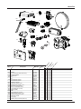
Short List ........................................................................................................................63
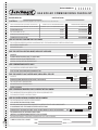
Benchmark - Gas boiler commissioning checklist .....................................65
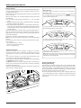
general information
This manual is an integral and essential part of the product. It
should be kept with the appliance so that it can be consulted by
the user and our authorised personnel.
Please carefully read the instructions and notices about the unit
contained in this manual, as they provide important information
regarding the safe installation, use and maintenance of the
product.
For operating instructions please consult the separate Users
Manual.
General Instructions
Read the instructions and recommendations in these Installation
and Servicing Instructions carefully to ensure proper installation,
use and maintenance of the appliance.
Keep this manual in a safe place. You may need it for your own
reference while Servicing Technicians or your installer may need
to consult it in the future.
The CLAS FF is a combined appliance for the production of central
heating (C.H.) and domestic hot water (D.H.W. - FF models).
The CLAS FF SYSTEM is a system boiler designed for the production
of (C.H.) only.
These appliances are for domestic use only and must be used only
for the purpose for which they have been designed.
The manufacturer declines all liability for damage caused by
improper or negligent use.
No asbestos or other hazardous materials have been used in the
fabrication of this product.
Before connecting the appliance, check that the information
shown on the data plate and the table in section 7 comply with
the electric, water and gas mains of the property. You will find the
data plate on the reverse of the control panel.
The gas with which this appliance operates is also shown on the
label at the bottom of the boiler.
Do not install this appliance in a damp environment or close to
equipment which spray water or other liquids.
Do not place objects on the appliance.
Do not allow children or inexperienced persons to use the
appliance without supervision.
If you smell gas in the room, do not turn on or off light switches,
use the telephone or any other object which might cause sparks.
Open doors and windows immediately to ventilate the room.
Shut the gas mains tap (at or adjacent to the gas meter) or the
valve of the gas cylinder and call your Gas Supplier immediately.
Always disconnect the appliance either by unplugging it from
the mains or turning off the mains switch before cleaning the
appliance or carrying out maintenance.
In the case of faults or failure, switch off the appliance and turn off
the gas tap. Do not tamper with the appliance.
For repairs, call your local Authorised Servicing Agent and request
the use of original spare parts. For in-guarantee repairs contact
MTS (GB) Limited.
3
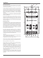
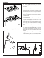
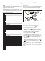
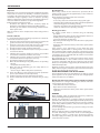
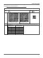
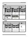
general information
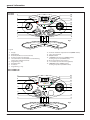
CLAS 24 FF
CLAS 30 FF
1
16
15
2
14
3
1
2
24
23
22
4
3
12
5
21
6
I
20
4
7
19
9
13
12
8
18
9
17
15
14
10
11
16
6
11
12
13
5
10
6
9
7
8
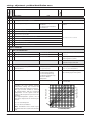
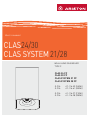
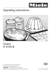
Fig. 1
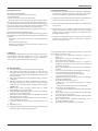
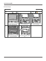
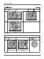
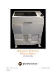
Legend
1.
2.
3.
4.
5.
6.
7.
8.
9.
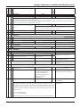
Display
RESET button
Red LED (illuminated = boiler lockout)
Heating System Pressure Gauge
Selector knob for Summer/Winter Central Heating
Temperature Adjustment Knob
Programming “-” key
MENU/OK button
ESC button
Programming “+” key
10.
11.
12.
13.
Domestic Hot Water adjustment knob (COMBI models)
Time clock (optional)
ON/OFF Switch
“COMFORT” Function L.E.D (COMBI models)
Heating only L.E.D (SYSTEM models)
14. Green led (auto function activate)
15. AUTO button (to active Thermoregulation)
16. COMFORT button (COMBI models)
Heating only button (SYSTEM models)
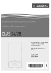
CLAS SYSTEM 21 FF
CLAS SYSTEM 28 FF
1
16
15
2
14
3
2
1
24
23
22
4
3
12
5
21
6
I
7
19
9
20
18
8
4
13
12
9
17
11
15
14
13
10
16
6
12
11
5
6
9
7
8
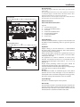
Fig. 2
4
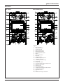
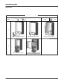
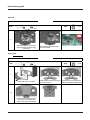
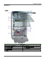
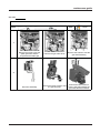
general information
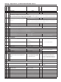
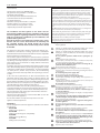
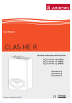
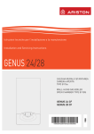
Overall wiew
CLAS 24/30 FF
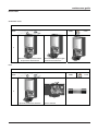
CLAS SYSTEM 21/28 FF
1
1
24
24
2
2
23
23
3
3
22
4
22
4
5
5
21
21
20
6
19
7
19
7
18
8
20
6
8
17
17
9
9
10
10
16
16
11
12
12
Fig. 3
13
14
14 15
Fig. 4
Legend
1.
2.
3.
4.
5.
6.
7.
8.
9.
10.
11.
12.
13.
14.
15.
16.
17.
18.
19.
20.
21.
22.
23.
24.
Flue connector
Air pressure switch
Condensate trap
Main Heat Exchanger
Overheat thermostat
Flow temperature probe
Burner
Ignition electrodes
Gas valve
Spark generator
D.H.W. temperature probe
Safety valve (3 bar)
Secondary heat exchanger
Drain valve
D.H.W. Flow switch
Circulation Pump with air release valve
Water pressure sensor
Diverter valve
Detection Electrode
Combustion Chamber Insulation Panel
Combustion Chamber
Expansion vessel
Fan
Combustion Analysis Test Point
5
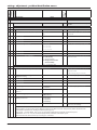
general information
ELECTRICAL PERFORMANCE
GEN. NOTES
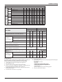
Technical Information
Model Name
CLAS 24 FF
CLAS 30 FF
CE certification (pin)
1312BR4793
1312BR4793
Boiler type
C12-C32-C42-C52-B22-B32
Max/min nominal heat input(Hi)
kW
25.8 / 11.0
30.0 / 13.0
Max/min nominal heat input (Hs)
kW
28.7 / 12.2
33.3 / 14.4
Max/min nominal heat input for hot water (Hi)
kW
27 / 11.0
31.3 / 13.0
Max/min nominal heat input for hot water (Hs)
kW
30 / 12.2
34.8 / 14.4
Heat output: max/min
kW
24.2 / 9.8
28.1 / 11.6
Heat output for hot water: max/min
kW
26.2 / 9.8
29.5 / 11.6
Combustion efficiency (at flue) Hi/Hs
%
95.0
93.9
Gross efficiency of nominal heat input (60/80 °C) Hi/Hs
%
94.8 / 84.5
93.6 / 84.3
Gross efficiency at 30 % at 47°C
%
93.6 / 84.3
93.2 / 83.9
%
89.2 / 80.3
89.3 / 80.4
***
***
Hi/Hs
Gross efficiency at minimum power Hi/Hs
Number of efficiency stars (Directive 92/42/EEC)
stars
Rating Sedbuk Band / %
class
D
D
Ma. heat loss to the casing (∆T = 50°C)
%
0.4
0.3
Heat loss through the flue when burner on
%
5.0
6.1
Heat loss through the flue when burner off
%
0.4
0.4
Pa
100
104
3
3
Residual discharge head
EMISSIONS IN C.H.
Nox class
Flue fumes temperature (G20)
°C
98
114
CO2 content2 (G20)
%
6.6
6.4
CO content (0 %02)
ppm
40
92
O2 content2 (G20)
%
8.7
8.9
97
67.5
62.8
74
Max Discharge of Products of Combustion (G20)
Excess air
HEATING CIRCUIT
Load losses water side (max) ∆T=20°C
200
200
bar
0.25
0.25
Expansion vessel pre-charged pressure
bar
1
1
Maximum central heating circuit pressure
bar
3
3
Domestic hot water temperature max/min (Approx)
DOMESTIC HOT WATER CIRCUIT
%
mbar
Central heating temperature: max/min (Approx)
8
8
°C
l
85 / 35
85 / 35
°C
60 / 36
60 / 36
Specific flow rate of domestic hot water system (10 min. with ∆T=30°C)) instant boilers
l/min
12.5
14.1
D.H.W. flow rate ∆T=25°C
l/min
15.0
16.9
D.H.W. flow rater ∆T=35°C
l/min
10.7
12.1
Hot water comfort stars (EN13203)
stars
3
3
D.H.W. minimum flow rate
l/min
1.7
1.7
7
7
230/50
230/50
127
136
Domestic hot water pressure max
Power supply voltage/frequency
ROOMELECTRICAL
DATA
kg/h
Residual head for the system
Expansion vessel capacity
bar
V/Hz
Power consumption
W
Minimum operating room temperature
°C
+5
+5
Electric system grades of protection
IP
X5D
X5D
Weight
Dimensions (W x H x D) :
6
class
kg
mm
31
31
400/770/315
400/770/315
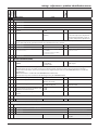
general information
GEN. NOTES
Model Name
CE certification (pin)
ELECTRICAL PERFORMANCE
Boiler type
EMISSIONS IN C.H.
CLAS SYSTEM
28 FF
1312BR4793
1312BR4793
C12-C32-C42-C52-B22-B32
Max/min nominal heat input(Hi)
kW
25.8 / 11.0
30.0 / 13.0
Max/min nominal heat input (Hs)
kW
28.7 / 12.2
33.3 / 14.4
Max/min nominal heat input for hot water (Hi)
kW
27 / 11.0
31.3 / 13.0
Max/min nominal heat input for hot water (Hs)
kW
30 / 12.2
34.8 / 14.4
Heat output: max/min
kW
24.2 / 9.8
28.1 / 11.6
Combustion efficiency (at flue) Hi/Hs
%
95.0
93.9
Gross efficiency of nominal heat input (60/80 °C) Hi/Hs
%
94.8 / 84.5
93.6 / 84.3
Gross efficiency at 30 % at 47°C
Hi/Hs
Gross efficiency at minimum power Hi/Hs
%
93.6 / 84.3
93.2 / 83.9
%
89.2 / 80.3
89.3 / 80.4
Number of efficiency stars (Directive 92/42/EEC)
stars
***
***
Rating Sedbuk
class
D
D
Ma. heat loss to the casing (∆T = 50°C)
%
0.4
0.3
Heat loss through the flue when burner on
%
5.0
6.1
Heat loss through the flue when burner off
%
0.4
0.4
Residual discharge head
mbar
100
104
Nox class
class
3
3
°C
98
114
Flue fumes temperature (G20)
CO2 content2 (G20)
CO content (0 %02)
O2 content2 (G20)
Max Discharge of Products of Combustion (G20)
Excess air
%
6.6
6.4
ppm
40
92
%
8.7
8.9
Kg/h
97
67.5
%
62.8
74
mbar
200
200
Residual head for the system
bar
0.25
0.25
Expansion vessel pre-charged pressure
bar
1
1
Maximum central heating circuit pressure
bar
3
3
l
8
8
Load losses water side (max) ∆T=20°C
HEATING CIRCUIT
CLAS SYSTEM
21 FF
Expansion vessel capacity
°C
85 / 35
85 / 35
Domestic hot water temperature max/min (Approx)
°C
60 / 36
60 / 36
V/Hz
230/50
230/50
DOMESTIC HOT WATER CIRCUIT
Central heating temperature: max/min
ROOMELECTRICAL
DATA
Power supply voltage/frequency
Power consumption
W
127
136
Minimum operating room temperature
°C
+5
+5
Electric system grades of protection
IP
X5D
X5D
Weight
kg
31
31
400/770/315
400/770/315
Dimensions (W x H x D) :
mm
7
installation
Reference Standards
The technical information and instructions provided herein below are
intended for the installer / Servicing Technician so that the unit may
be installed and serviced correctly and safely.
In the United Kingdom the installation and initial start up of the
boiler must be by a CORGI Registered Installer in accordance with the
installation standards currently in effect, as well as with any and all
local health and safety standards i.e. CORGI.
In the Republic of Ireland the installation and initial start up of the
appliance must be carried out by a Competent Person in accordance
with the current edition of I.S.813 “Domestic Gas Installations”, the
current Building Regulations, reference should also be made to the
current ETCI rules for electrical installation.
This appliance must be installed by a competent installer in accordance
with current Gas Safety (installation & use) Regulations.
The installation of this appliance must be in accordance with the
relevant requirements of the Local Building Regulations, the current
I.E.E. Wiring Regulations, the bylaws of the local water authority,
in Scotland, in accordance with the Building Standards (Scotland)
Regulation and Health and Safety document No. 635 “Electricity at
work regulations 1989” and in the Republic of Ireland with the current
edition of I.S. 813, the Local Building Regulations (IE).
Siting the Appliance
The appliance may be installed in any room or indoor area, although
particular attention is drawn to the requirements of the current I.E.E.
Wiring Regulations, and in Scotland, the electrical provisions of the
Building Regulations applicable in Scotland, with respect to the
installation of the combined appliance in a room containing a bath
or shower, the location of the boiler in a room containing a bath or
shower should only be considered if there is no alternative.
Where a room-sealed appliance is installed in a room containing a
bath or shower the appliance and any electrical switch or appliance
control, utilising mains electricity should be situated so that it cannot
be touched by a person using the bath or shower, specifically in
accordance with current IEE Wiring Regulations.
The location must permit adequate space for servicing and air
circulation around the appliance as indicated on page 9.
The location must permit the provision of an adequate flue and
termination.
For unusual locations special procedures may be necessary.
BS 6798-1987 gives detailed guidance on this aspect.
A compartment used to enclose the appliance must be designed
specifically for this purpose. No specific ventilation requirements are
needed for the installation within a cupboard.
This appliance is not suitable for outdoor installation.
C.O.S.H.H.
Materials used in the manufacture of this appliance are non-hazardous
and no special precautions are required when servicing.
Installation should also comply with the following British Standard
Codes of Practice
BS 7593:1992
Treatment of water in domestic hot
water central heating systems
BS 5546:1990
Installation of hot water supplies for
domestic purposes
BS 5440-1:2000 Flues
BS 5440-2:2000 Air supply
BS 5449:1990
Forced circulation hot water systems
BS 6798:1987
Installation of gas fired hot water
boilers of rated input not exceeding
60kW
BS 6891:1989
Installation of low pressure gas pipe
up to 28mm
BS 7671:2001
IEE wiring regulations
BS 4814:1990
Specification for expansion vessels
BS 5482:1994
Installation of L.P.G.
and in the Republic of Ireland in accordance with the following Codes
of Practice:
I.S. 813
8
Domestic Gas Installations
The type C appliances (in which the combustion circuit, air vent intake
and combustion chamber are air-tight with respect to the room in
which the appliance is installed) can be installed in any type of room.
Secondary ventilation is not required with this boiler. The boiler must
be installed on a solid, non-combustible, permanent wall to prevent
access from the rear.
installation
200
120
180
120
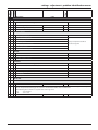
Fig. 5
150
28
67 67 65
B
A
770
770
65
120
CLAS SYSTEM 21/28 FF
770
CLAS 24/30 FF
CLAS SYSTEM 21/28 FF
200
132
315
B
132
28
120
200
25
200
Overall Dimensions
Legend:
A = Central Heating Flow (22mm nut & olive)
B = Domestic Hot Water Outlet (15mm nut & olive)
C = Gas Inlet (15mm)
D = Domestic Cold Water Inlet (15mm nut & olive)
E = Central Heating Return (22mm nut & olive)
D
Clearances
In order to allow access to the interior of the boiler for
maintenance purposes, the boiler must be installed in
compliance with the minimum clearances indicated in Fig. 6
C
B
A
B
A
B
C
D
E
=
=
=
=
=
450 mm
60 mm
300 mm
450 mm
350 mm
D
E
Fig. 6
9
installation
ø80
ø100
ø80
250
105
120
120
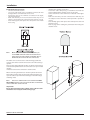
Drill the wall and plug using those supplied with the connections
kit, position the hanging bracket and secure with the wall bolts
supplied, assembl the connection kit and secure to the wall.
Position the appliance on the hanging bracket and connect the
valves to the boiler connections. (see also Gas Connections, Water
Connections - page 11).
Important!
In the event that the power supply cord must be changed, replace
it with one with the same specifications.
Note: The diagrams for the electrical system and external wiring
configurations can be found on pages ?? and ??.
Should external controls be required, the design of the external
electrical circuits should be undertaken by a competent person.
Warning, this appliance must be earthed.
External wiring to the appliance must be carried out by a
competent person and be in accordance with the current I.E.E.
Regulations and applicable local regulations.
The appliance is supplied with a fly-lead already connected,
this must be connected to a 240v supply fused at 3A and must
facilitate complete electrical isolation of the appliance, by the use
of a fused double pole isolator having a contact separation of at
least 3 mm in all poles or alternatively, by means of a 3 A fused
three pin plug and unswitched shuttered socket outlet both
complying with BS 1363.
The point of connection to the Electricity supply must be readily
accessible and adjacent to the appliance unless the appliance
is installed in a bathroom when this must be sited outside the
bathroom.
10
ø 80 + ø 80
105
180
105
195
ø 60/100 - ø 80/125
180
120
150
150
315
315
300
65
67
67
65
20
50
The boiler operates with alternating current, as indicated in
the Technical Information tables on pages 6 and 7, where the
maximum absorbed power is also indicated. Make sure that the
connections for the neutral and live wires correspond to the
indications in the diagram. The appliance electrical connections
are situated on the reverse of the control panel.
770
725
Electrical Connection
For safety purposes, have a competent person carefully check the
electrical system in the property, as the manufacturer will not be
held liable for damage caused by the failure to earth the appliance
properly or by anomalies in the supply of power. Make sure that
the residential electrical system is adequate for the maximum
power absorbed by the unit, which is indicated on the rating
plate. In addition, check that the section of cabling is appropriate
for the power absorbed by the boiler.
330
580
830
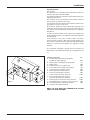
Place the template in the position the appliance is to be mounted
and after ensuring it is hanging squarely, use it to drill the holes for
the hanging bracket and flue pipe(s) NB: For further information
relating to the flue installation please refer to Flue Installation page 13. (If the appliance is to be fitted on a wall of combustible
material, the wall must be protected by a sheet of fireproof
material).
If the appliance is to be fitted into a timber framed building,
guidance should be sought from the Institute of Gas Engineers
document Ref: IGE/UP/7.
195
ø80
90
Mounting the Appliance
After removing the boiler from its packaging, remove the template
from the box. Note: Pay particular attention to any test water that
may spill from the appliance.
3/4"
1/2"
3/4"
1/2"
3/4"
400
Fig. 7
installation
Gas Connection
The local gas region contractor connects the gas meter to the
service pipe.
If the gas supply for the boiler serves other appliances ensure that
an adequate supply is available both to the boiler and the other
appliances when they are in use at the same time.
Pipe work must be of an adequate size. Pipes of a smaller size than
the boiler inlet connection must not be used.
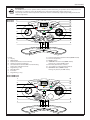
CLAS 24/30 FF
Water Connections
View of the Boiler Connections
F
A
B
C
D
E
H
Central Heating
Detailed recommendations are given in BS 6798:1987 and
BS 5449-1:1990, the following notes are given for general
guidance.
CLAS SYSTEM 21/28 FF
F
A
E
C
H
Fig. 8
Legend:
A = Central Heating Flow
B = Domestic Hot Water Outlet
C = Gas Inlet
D = Domestic Cold Water Inlet
E = Central Heating Return
F = Safety Valve Outlet
H = Drain valve
Pipe Work:
Copper tubing to BS EN 1057:1996 is recommended
for water pipes. Jointing should be either with capillary
soldered or compression fittings.
Where possible pipes should have a gradient to ensure air
is carried naturally to air release points and water flows
naturally to drain taps.
The appliance has a built-in automatic air release valve,
however it should be ensured as far as possible that the
appliance heat exchanger is not a natural c o l l e c t i n g
point for air.
Except where providing useful heat, pipes should be
insulated to prevent heat loss and avoid freezing.
Particular attention should be paid to pipes passing through
ventilated spaces in roofs and under floors.
By-pass:
The appliance includes an automatic by-pass valve, which
protects the main heat exchanger in case of reduced or
interrupted water circulation through the heating system,
due to the closing of thermostatic valves or radiators.
System Design:
This boiler is suitable only for sealed systems.
Drain Cocks:
These must be located in accessible positions to permit the
draining of the whole system and should be fitted at all low
points. The taps must be at least 15mm nominal size and
manufactured in accordance with BS 2870:1980.
11
installation
Safety Valve Discharge:
The discharge should terminate facing downward on the
exterior of the building in a position where discharging
(possibly boiling water & steam) will not create danger or
nuisance, but in an easily visible position, and not cause
damage to electrical components and wiring.
The discharge must not be over an entrance or a window or
any other type of public access.
GAS
Air Release Points:
These must be fitted at all high points where air naturally
collects and must be sited to facilitate complete filling of
the system.
The appliance has an integral sealed expansion vessel to
accommodate the increase of water volume when the
system is heated.
It can accept up to 8 litres (1.8 gal) of expansion water. If
the heating circuit has an unusually high water content,
calculate the total expansion and add an additional sealed
expansion vessel with adequate capacity. This should be
located on the return pipe work as close as possible to the
pump inlet.
GAS
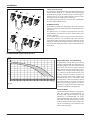
Fig. 9
Residual Head of the Boiler ΔT 20°C
mbar
500
450
400
350
300
250
200
150
100
50
0
0
100
200
300
400
500
600
700
800
900
1000
1100
1200
1300
l/h
Fig. 10
Mains Water Feed - Central Heating:
A method for initially filling the heating
system is supplied with the connection kit.
The filling loop is connected between the
cold water inlet and the central heating
flow connections, and incorporates a nonreturn valve. To operate the filling loop,
it is necessary to open both quarter turn
handles, once the required pressure has
been achieved, close both handles and
disconnect the hose in accordance with
water byelaws. Note: The installer should
ensure that there are no leaks as frequent
filling of the heating system can lead to
premature scaling of the main exchanger
and failure of hydraulic components.
Domestic Water:
The domestic water must be in accordance
with the relevant recommendation of
BS 5546:1990. Copper tubing to BS EN
1057:1996 is recommended for water
carrying pipe work and must be used for
pipe work carrying drinking water, a scale
reducer should also be used to reduce the
risk of scale forming in the domestic side
of the heat exchanger.
12
installation
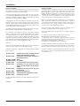
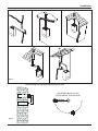
Flue Connections
Flue System
The provision for satisfactory flue termination must be
made in accordance with BS 5440-1.
The appliance must be installed so that the flue terminal is
exposed to outside air.
The terminal must not discharge into another room or
space such as an outhouse or lean-to.
It is important that the position of the terminal allows a free
passage of air across it at all times.
The terminal should be located with due regard for the
damage or discolouration that might occur on buildings in
the vicinity and consideration must be given to adjacent
boundaries.
In cold or humid weather water vapour may condense on
leaving the flue terminal. The effect of such “pluming” must
be considered.
If the terminal is less than 2 metres above a balcony,
above ground or above a flat roof to which people have
access, then a suitable terminal guard must be fitted. When
ordering a terminal guard, quote the appliance model
number.
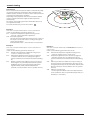
The minimum acceptable spacing from the terminal to
obstructions and ventilation openings are specified in Fig.
11.
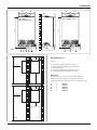
Fig. 11
TERMINAL POSITION
A - Directly above or below an openable
window or other opening
B - Below gutters, solid pipes or drain pipes
C - Below eaves
D - Below balconies or car-port roof
E - From vertical drain pipes and soil pipes
F - From internal or external corners
G - Above ground or balcony level
H - From a surface facing a terminal
I - From a terminal facing a terminal
J - From an opening in the car port
(e.g. door, window) into dwelling
K - Vertically from a terminal in the same wall
L - Horizontally from a terminal in the same wall
M - Horizontally from an opening window
N - Fixed by vertical flue terminal
mm
300
75
200
200
150
300
300
600
1200
1200
1500
300
300
NOTE: THE FLUE MUST NOT TERMINATE IN A PLACE
LIKELY TO CAUSE NUISANCE.
13
installation
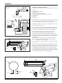
Fitting the Coaxial Flue (Horizontal)
(For Vertical Flue and Twin Pipe Instructions see pages 13 and 14)
Fig. 12
Contents:
1x Silicone O-Ring (60mm)
1x Elbow (90o)
2x Wall Seals (Internal & External)
1x Flue Pipe including Terminal (1 metre - 60/100)
2x Flue Clamps
4x Screws
2x Foam Seals
80 mm
Once the boiler has been positioned on the wall, insert the elbow
into the socket (Fig 12) and rotate to the required position. Note:
It is possible to rotate the elbow 360o on its vertical axis.
Using the flue clamps, seals and screws supplied (Figs. 12 and 14)
secure the elbow to the boiler.
The 1 metre horizontal flue kit (3318000) supplied is suitable for
an exact X dimension of 811mm, and the 750mm horizontal flue
kit (3318001) is suitable for an exact X dimension of 699mm.
Measure the distance from the face of the external wall to
the face of the flue elbow (X - Fig 12), add 23 mm to this
measurement, you now have the total length of flue required
(including the terminal), this figure must now be subtracted from
860mm, you now have the total amount to be cut from the plain
end of the flue.
Cut the flue to the required length ensuring that the distance
between the inner and the outer flue is maintained (Fig 2.8).
e.g.
X = 508mm + 22mm = 530mm
860 - 530 = 330mm (Length to be cut from the plain end
of the flue).
23 mm
23 mm
Fig. 13
23
mm
Once cut to the required length, ensure that the flue is free from
burrs and reassemble the flue. If fitting the flue from inside of the
building attach the grey outer wall seal to the flue terminal and
push through the flue through the hole, once the wall seal has
passed through the hole, pull the flue back until the seal is flush
with the wall. Alternatively, the flue can be installed from outside
of the building, the grey outer seal being fitted last.
Fig. 14
Flue Clamp
Foam Seal
Screws
23
14
mm
installation
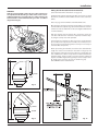
WARNING
If the chosen flue length requires the use of the restrictor, it is
already fitted inside the flue gas collar. In the event of an installation which does not require the use of the restrictor, the
latter should be removed from the flue gas collar. See table A
(Page 20 and Fig 15).
Fitting 80/125 Flue (Horizontal and Vertical)
(For Coaxial Vertical Flue Instructions see page 13)
Should the flue require extending, the flue connections are push
fit, however, one flue bracket should be used to secure each metre
of flue.
Note: See page 20 for maximum and minimum flue runs.
Fig. 15
Once the boiler has been positioned on the wall, it is necessary to
insert the Ø80/125 adaptor (Fig. 18) for both horizontal and vertical flue runs into the boiler flue socket (not supplied with flue kit
- Part No 3318040).
Push the adaptor onto the boilers flue connection, grease the
seals then add extensions or elbows as required, secure the adaptor, using the clamp and screws provided.
To fit extensions or elbows it is first necessary to ensure that the
lip seal is fitted correctly into the inner flue, once verified, it is simply necessary to push them together, no clamps are necessary to
secure the flue components.
Before proceeding to fit the flue, ensure that the maximum flue
length has not been exceeded (See the tables on Page 20) and
that all elbows and bends have been taken into consideration, for
each additional 90o elbow 1 metre must be subtracted from the
total flue length, and for each 45o 0.5 metres must be subtracted
from the total flue length (the height of the vertical adaptor and a
45o bend can be seen in Fig. 17 and a 90o bend in Fig. 16).
Note: DO NOT cut the vertical flue kit.
3318036
3318040
Fig. 16
180mm
3318040
3318037
3318040
Fig. 17
Fig. 18
15
installation
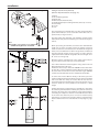
Fig. 19
Fitting the Coaxial Flue (Vertical)
(For Twin Pipe Instructions see page 17)
Contents:
1x Silicone O-Ring (60mm)
1x Elbow (90o)
2x Wall Seals (Internal & External)
1x Aluminium Flue Pipe including Terminal (Telescopic - 60/100)
2x Flue Clamps
8x Screws
2x Seals
The vertical flue kit is supplied with a specially designed weather
proof terminal fitted, it can be used either with a flat roof or a
pitched roof. (see Figs 20 and 21).
The Vertical flue kits maximum and minimum useable lengths
with both flat and pitched roof flashings are indicated in (Figs. 20
and 21).
Note:
Max Length = a+a+a +b+b = a+a+a+0.5+0.5
Combined Length not to exceed 4m
Fig. 20
Before proceeding to fit the flue, ensure that the maximum flue
length has not been exceeded and that all elbows and bends
have been taken into consideration, the maximum flue length is 4
metres, for each additional 90o elbow 1 metre must be subtracted
from the total flue length, and for each 45o 0.5 metres must be
subtracted from the total flue length (the offset and height of 2 x
45o can be seen in Fig. 22b).
Mark the position of the flue hole in the ceiling and/or roof (see
Fig. 20 for distance from wall to the centre of the flue).
Cut a 125mm diameter hole through the ceiling and/or roof and
fit the flashing plate to the roof.
Should it be necessary to cut the flue DO NOT cut the outer white
air inlet tube, cut the aluminium exhaust flue 6mm longer than
the outer white air tube when used at minimum length. DO NOT
cut more that 250mm from the inner aluminium exhaust flue.
180 mm
To connect the vertical flue kit directly to the boiler, place the
adaptor (supplied with vertical flue kit) onto the exhaust manifold
and secure with the clamp, the vertical flue kit must then be
inserted through the roof flashing, this will ensure that the correct
clearance above the roof is provided as the terminal is a fixed
height.
Fig. 21
Should extensions be required, they are available in 1 metre (Part
No. 3318005), 500mm (Part No. 3318006), they must be connected
directly to the boiler and secured with the clamp supplied before
connecting the adaptor to allow the vertical flue kit to be fitted.
In the event that extension pieces need to be shortened, they
must only be cut at the male end and it must be ensured that the
distance between the inner and outer flue are kept (Fig. 2.8, page
11).
16
installation
WARNING
If the chosen flue length requires the use of the restrictor, it is
already fitted inside the flue gas collar. In the event of an installation which does not require the use of the restrictor, the
latter should be removed from the flue gas collar. See table A
(Page 20 and Fig 22b).
When utilising the vertical flue system, action must be taken to
ensure that the flue is supported adequately to prevent the weight
being transferred to the appliance flue connection.
When the flue passes through a ceiling or wooden floor, there must
be an air gap of 25mm between any part of the flue system and any
combustible material. The use of a ceiling plate will facilitate this.
Also when the flue passes from one room to another a fire stop
must be fitted to prevent the passage of smoke or fire, irrespective
of the structural material through which the flue passes.
Fig. 22a
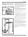
Fitting the Flue (Twin Pipe)
Where it is not possible to terminate the flue within the distance
permitted for coaxial flues, the twin flue pipe can be used by fitting
a special adaptor to the flue connector and using the aperture for
the air intake located on top of the combustion chamber.
For twin flue installation it is most important to avoid any possible
condense formation entering the appliance.
Should there be the possibility of condensation forming within
the flue, there are two options;
1) Where condense will form but can be negated with insulated
flue, install the insulated flue with a fall of 5mm in every metre
away from the boiler.
2) The exhaust flue will have a fall of 3o back to the boiler and a
suitable trap will be fitted on the exhaust as close to the boiler
as possible, condense will then be suitably disposed of.
Where the flue runs through cold spots, i.e. loft areas, condense
is likely to be formed, therefore a fall back to the boiler and a trap
is required.
Always ensure that the flue is adequately supported, avoiding low
points. (MTS supply suitable clamps as Part No. 705778).
Minimum offset distance when using 2x 45° bends
To utilise the air intake it is necessary to:
Remove the blank intake by cutting it with a suitable knife (Fig.
23, page 20);
Insert the elbow/flue pipe into the air intake until it stops;
The twin flue pipes can be fitted with or without additional elbows
and need no clamps, simply ensure that the red o-ring is inserted
in the female end of the flue pipe and push the extension piece
fully into the previous section of flue pipe or elbow, check that the
o-ring is not dislodged when assembling the flue.
Twin pipe can also be converted back to Coaxial flue to enable
vertical termination with a coaxial kit by using the pipe bridge
(Twin - Coaxial Adaptor - Part No. 3318030). When running the
twin flue pipe vertically, a condense trap must always be used on
the exhaust pipe.
It is not possible to use the pipe bridge for horizontal
termination.
Fig. 22b
17
installation
Note:
Vertical twin flue installations must have a trap on the
exhaust. MTS supply a suitable condense trap Part No. 3318026
and recommend that this be used in the event that the flue may
form condense.
When siting the twin flue pipe, the air intake and exhaust terminals
must terminate on the same wall, the centres of the terminals must
be a minimum of 280 mm apart and the air intake must not be
sited above the exhaust terminal (refer to Fig. 27). The air intake
pipe can be run horizontally, however, the terminal and the final 1
metre of flue must be installed with a fall away from the boiler to
avoid rain ingress.
It is also strongly recommended that the air intake pipe run be
constructed of insulated pipe to prevent condense forming on
the outside of the tube.
The maximum permissible flue length for twin flue is dependent
on the type of installation.
Fig. 23
IMPORTANT!!!
Where condense will form within the flue system, ensure there is
a fall back to the boiler of 3oand a suitable trap is fitted as close
to the boiler as possible. MTS supply a suitable collector Part No.
3318026.
Fig. 24
For flue runs with the intake and exhaust pipes under the same
atmospheric conditions (Type 4) the maximum length is 44 metres
(31kW), for runs with the terminals under different atmospheric
conditions (Type 5) the exhaust terminal must extend 0.5 metres
above the ridge of the roof (this is not obligatory if the exhaust
and air intake pipes are located on the same side of the building).
For Type 5 also, the maximum permissible combined length is 40
metres.
The maximum length is reached by combining the total lengths
of both the air intake and exhaust pipes. Therefore a maximum
length of 40 metres for example, will allow a flue run of 20 metres
for the air intake and 20 metres for the exhaust pipes, also for each
90o elbow 1.3 metres must be subtracted from the total length
and for each 45o elbow 1 metre must be subtracted from the total
flue length.
Some of the acceptable flue configurations are detailed on page
19 (Fig. 26).
For further information relating to flue runs not illustrated, please
contact the Technical Department on 0870 241 8180.
Fig. 25
18
105
195
120
180
installation
Fig. 26
Note: Drawings are indicative of flueing options only.
AIR INTAKE MUST NOT BE
FITTED ABOVE THE EXHAUST
AIR INTAKE
EXHAUST
AIR INTAKE
Fig. 27
19
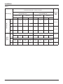
installation
TABLE A
MAXIMUM EXTENSION EXHAUSTAIR (m)
CLAS 24 FF
CLAS SYSTEM 21 FF
Exhaust Type
Do not use
Restrictor
Coaxial Systems
Restrictor ø 44
Twin Pipe
Systems
Do not use
Restrictor
Restrictor ø 44
MIN
MAX
MIN
MAX
MIN
MAX
MIN
MAX
C12
C32
C42
0,5
0,75
0,75
4
0,5
0,75
0,75
4
B32
0,5
0,75
0,75
4
0,5
0,75
0,75
4
C12
C32
C42
0,5
3
3
11
0,5
3
3
11
B32
0,5
C12
C32
C42
20
Diameter
of pipe
(mm)
CLAS 30 FF
CLAS SYSTEM 28 FF
ø 60/100
ø 80/125
3
3
11
0,5
3
S1 = S2
3
11
11/11
25/25
S1 = S2
ø 80/80
0,5/0,5
15/15
15/15
26/26
0,5/0,5
11/11
1 + S2
1 + S2
C52
C82
1/0,5
1/34
1/34
1/53
1/0,5
1/27
1/27
1/51
B22
0,5
35
35
54
0,5
28
28
52
ø 80/80
ø 80
installation
WARNING
Before performing any work on the boiler, first
disconnect it from the electrical power supply using
the external bipolar switch.
Electrical connections
For increased safety, ask a qualified technician to perform a
thorough check of the electrical system.
The manufacturer is not responsible for any damage caused by
the lack of a suitable earthing system or by the malfunctioning of
the electricity mains supply.
Make sure that the system is able to withstand the maximum
power absorbed by the boiler (this is indicated on the appliance
data plate). Check that the section of the wires is suitable and is
not less 1.5 mm2
The appliance must be connected to an effiecient earthing system
if it is to operate correctly.
The power supply cable must be connected to a 230V-50Hz
network, where the L-N poles and the earth connection are all
respected.
Important!
In the event that the power supply cable must be changed, replace
it with one with the same specifications.
Peripheral unit connection
To access peripheral unit connections carry out the following steps:
- Disconnect the boiler from the power supply
- Remove the casing by unhooking it from the instrument panel
- Rotate the control panel while pulling it forwards
- Unscrew the two screws on the back cover of the instrument
panel
- Unhook the right side clip and the right front clip; then lift the flap
The terminal board (see figure) may be accessed in order to connect:
Outdoor sensor (not suitable for use on CLAS HE SYSTEM)
Room thermostat 1
Room thermostat 2
Optional P.C.B.s can also be entered for further accessories:
BUS P.C.B.
For the connection of the
Clima Manager remote control
Modulating room sensor
Caution!
For the connection and positioning of the wires belonging to optional peripheral units, please refer to the
advice relating to the installation of these units.
Power supply cable
Fig. 28
120
H03V2V2-F
140
Important!
Connection to the electricity mains supply must
be performed using a fixed connection (not with a
mobile plug) and a bipolar switch with a minimum
contact opening of 3 mm must be fitted.
The use of multiplugs, extension leads or adaptors is strictly
prohibited.
It is strictly forbidden to use the piping from the hydraulic, heating
and gas systems for the appliance earthing connection.
The boiler is not protected against the effects caused by lightning. If the
mains fuses need to be replaced, use 2A rapid fuses.
Fig. 30
WARNING
For the connection and positioning of the wires belonging to
optional peripheral units, please refer to the advice relating
to the installation of these units.
Fig. 31
TA1 TA2 SE
bus-translator
(optional)
Optional P.C.B.
AMPC-GAL1
Fig. 29
21
installation
Room thermostat connection
-
Introduce the thermostat wire
Loosen the cable clamp using a screwdriver and insert the wires
leading from the room thermostat one at a time.
Connect the wires to the terminals as indicated in the figure,
removing the jumper
Make sure that they are well connected and that they are not
subject to traction when the control panel lid is opened or closed
Close the flap again, then replace the control panel cover and the
front casing.
NOTE:
WHEN CONNECTING THE BOILER TO EXTERNAL CONTROLS, DO
NOT RUN 240V CABLES AND CABLES FOR SWITCHING CIRCUITS
(WHICH ARE LOW VOLTAGE) TOGETHER, USE SEPERATE CABLES TO
PREVENT INDUCED VOLTAGE ON THE LOW VOLTAGE CIRCUITS.
The boiler can be connected to a central heating system that
uses two zone valves to allow connection to an indirect storage
cylinder.
There are two wiring diagrams shown, one for the connection to
an Unvented Cylinder and one for connection to an open vented
cylinder.
In both cases the boiler connection is shown as TA1.
When connecting the boiler to an external cylinder do not run
240V cables and the cables for the room terminal together, use
separate cables to prevent induced voltage on the low voltage
switching circuit.
NOTE:
THE USE OF A ‘Y’ PLAN SYSTEM IS NOT POSSIBLE WITH THE CLAS
HE SYSTEM BOILER DUE TO THE LOW VOLTAGE SWITCHING OF THE APPLIANCE
UNLESS SUITABLE RELAY CONTROLS ARE USED.
Important!!
Ensure that a balancing valve is fitted on the cylinder return
and balanced correctly at commissioning stage.
Outdoor sensor connection
22
- Introduce the outdoor sensor wires
- Loosen the cable clamp using a screwdriver and insert the
wires leading from the outdoor sensor one at a time.
- Connect the wires to the terminals as indicated in the figure
below;
- Make sure that they are well connected and that they are
not subject to stress when the control panel lid is opened or
closed;
- Close the flap again, then replace the control panel cover and
the front casing.
- Refer to page 39 for setting the parameters when using the
outdoor sensor.
installation
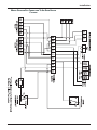
WIRING DIAGRAM FOR CONNECTION TO AN OPEN VENTED
CYLINDER
23
installation
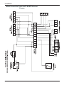
WIRING DIAGRAM FOR CONNECTION TO AN MTS UNVENTED
CYLINDER
24
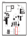
6
D.H.W.
Flow Switch
1
12 11 10 9 8 7 6 5 4 3 2 1
CN22
11 10 9 8 7 6 5 4 3 2 1
CN04
REMOTE CONTROL
8
8 7 6 5 4 3 2 1
1
Room Thermostat 2 (Optional)
External Sensor (Optional)
4
CN07
3
1
2
2
1
Room Thermostat 1 (Optional)
6
TA1
TA2
SE
5
ZONE1 FILLING1 PUMP PUMP
SPEED
4
SE
ON
Display
EARTH
Overheat
Thermostat
Detection
Electrode
FLAME
C.H. Return
Temperature Probe
C.H. Flow
Temperature Probe
12 11 10 9 8 7 6 5 4 3 2 1
CN22
Spark Generator
Gas valve
modulator
SPARK
GENERQTOR
4 3 2 1
GAS
VALVE
BUS Connection
FUSE 2AT
CN04
11 10 9 8 7 6 5 4 3 2 1
FAN 1
5
2 3
TA2
1
1
TA1
Fan
N
Modulating Pump
L
Motorised
diverter valve
installation
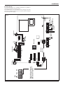
Electrical diagram
For increased safety, ask a qualified technician to perform a
thorough check of the electrical system.
The manufacturer is not responsible for any damage caused by
the lack of a suitable earthing system or by the malfunctioning of
the electricity mains supply.
Fig. 32
FLOW
25
6
Room Thermostat 2 (Optional)
External Sensor (Optional)
12 11 10 9 8 7 6 5 4 3 2 1
CN22
CN04
CN07
11 10 9 8 7 6 5 4 3 2 1
1
Room Thermostat 1 (Optional)
4
TA1
TA2
SE
3
8 7 6 5 4 3 2 1
8
2
1
FAN 1
GAS
VALVE
ON
Display
Gas valve
modulator
SPARK
GENERQTOR
4 3 2 1
BUS Connection
FUSE 2AT
CN04
11 10 9 8 7 6 5 4 3 2 1
1
1
2
6
1 PUMP PUMP
SPEED
5
SE
4
TA2
5
2 3
26
1
1
TA1
N
Fan
L
Modulating Pump
Detection
Electrode
C.H. Return
Temperature Probe
Overheat
Thermostat
Air Pressure
Switch
C.H. Flow
Temperature Probe
EARTH
12 11 10 9 8 7 6 5 4 3 2 1
CN22
Spark Generator
FLAME
installation
Fig. 33
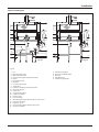
installation
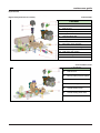
Water Circuit Diagram
21
21
1
1
2
2
3
3
20
4
20
4
19
5
18
6
7
19
5
18
6
7
8
17
17
16
16
9
10
15
11
14
13
12
11
9
13
12
Fig. 34
A
B
C
Fig. 35
D E
A
C
E
Legend:
1.
2.
3.
4.
5.
6.
7.
8.
9.
10.
11.
12.
13.
14.
15.
16.
17.
18.
19.
20.
21.
Fan
Main Heat Exchanger
Overheat Thermostat
Central Heating Flow Temperature Probe
Burner
Ignition Electrodes
Gas Valve
Secondary Exchanger
Safety valve
Domestic Hot Water Temperature Probe
Automatic By-pass
Drain valve
Central Heating Filter
D.H.W. Flow Switch
Diverter valve
Pressure Gauge
Modulating Circulation Pump with air release valve
Detection electrode
Expansion vessel
Central Heating Return Temperature Probe
Air Pressure Switch
A
B
C
D
E
Central Heating Flow
Domestic Hot Water Outlet
Gas Inlet
Cold Water Inlet
Central Heating Return
27
commissioning
Initial Preparation
MTS (GB) Limited support the
initiative. Within the
information pack you will find a copy of the
logbook.
It is important that this is completed in the presence of your
customer, they are shown how to use it, and it is signed by them.
Please instruct your customer that they must have their
log book with them whenever they contact a service engineer or
us.
damaging the boiler and system.
Failure to carry out this procedure may invalidate the appliance
warranty.
Preliminary electrical system checks to ensure electrical safety
must be carried out by a competent person i.e. polarity, earth
continuity, resistance to earth and short circuit.
Initial Start-up
Filling the Heating System:
Lower the control panel and remove the case panels.
Open the central heating flow and return cocks supplied with
the connection kit (there are two isolation points on the return
connection).
Unscrew the cap on the automatic air release valve one full turn
and leave open permanently.
Close all air release valves on the central heating system.
Gradually open valve(s) at the filling point (filling-loop) connection
to the central heating system until water is heard to flow, do not
open fully.
Open each air release tap starting with the lowest point and close
them only when clear water, free of air, is visible.
Purge the air from the pump by unscrewing the pump plug
anticlockwise, also manually rotate the pump shaft in the direction
indicated by the pump label to ensure the pump is free.
Refit the pump plug.
Continue filling the system until at least 1.5 bar registers on the
pressure gauge.
Inspect the system for water soundness and remedy any leaks
discovered.
Filling of the D.H.W. System (COMBI only):
Close all hot water draw-off taps.
Open the cold water inlet cock supplied with the connection kit.
Open slowly each draw-off tap and close them only when clear
water, free of bubbles, is visible.
Gas Supply:
Inspect the entire installation including the gas meter, test for
tightness and purge the supply as described in BS 6891:1988.
Open the gas cock (supplied with the connection kit) to the
appliance and check the gas connections on the appliance for
leaks.
Flushing Procedure
When the installation and filling are completed, flush the system
while cold, refill, turn on the Central Heating system and run it until
the temperature has reached the boiler operating temperature.
The system must then be immediately flushed through.
The flushing procedure must be in line with BS 7593:1992 code
of practice for treatment of water in domestic hot water central
heating systems.
During this operation, we highly recommend the use of a central
heating flushing detergent (Fernox Superfloc or equivalent),
whose function is to dissolve any foreign matter that may be in
the system.
Substances different from these could create serious problems to
the pump or other components.
The use of an inhibitor in the system such as Fernox MB-1 or
equivalent is strongly recommended to prevent corrosion (sludge)
28
The checks to be run before initial start-up are as follows:
1. Make sure that:
- the cap on the automatic air valve has been loosened
when the system is full;
- If the water pressure in the system is below 1.5 bar, bring it
up to the appropriate level;
- Make sure that the electrical connection has been made
properly and that the earth wire is connected to an
efficient earthing system;
- Switch on the boiler (by pressing the ON/OFF button) and
select the standby mode, where no hot water or heating
requests are made.
- Start the deaeration cycle by pressing ESC for 5 seconds
The boiler will start a deaeration cycle lasting about 7
minutes. If you need to stop it press ESC.
- Loosen the cap on the head of the pump to eliminate any
air pockets;
- Repeat the procedure for bleeding the radiators of air;
- Open the hot water taps for a brief period;
- Check the system pressure and, if it has dropped, open the
filling loop again to bring the pressure back up to 1.5 bar.
2. Make sure that all radiator valves are open;
3. Check the minimum and maximum burner pressure values;
adjust if necessary using the values indicated in the table on
Page 29.
Description of Function
De-aeration cycle
During the filling stage or if there is excess air in the system, the
deaeration cycle can be activated by holding the ESC button for 5
seconds. The boiler will start a cycle which lasts approximately 7
minutes. When this is complete the menu screen will be restored.
The cycle may either be repeated, if necessary, or stopped by
pressing ESC. Press the ESC button until the normal display screen
is restored.
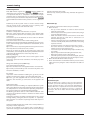
commissioning
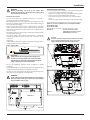
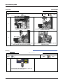
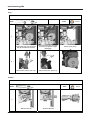
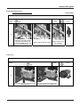
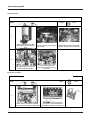
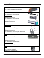
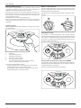
Checking the gas settings
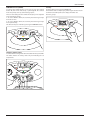
Remove the front casing and proceed as described below.
(a)
Supply working pressure check
1. Loosen screw “1” (Fig. a) and attach the pressure gauge
connection pipe onto the test nipple.
2. Switch the boiler on at maximum power, enabling the “flue
sweep” function (press the
button for 5 seconds; the
display will show “t -- “). The working pressure should correspond
to the value established in relation to the type of gas for which
the boiler is designed.
3. When the check is over, tighten screw “1” and make sure it is
securely in place.
4. The “flue sweep function” is automatically deactivated after 10
minutes or when the
button is pressed.
1
(b)
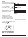
Checking the D.H.W. maximum power
1. To check the maximum power level, loosen screw “2” (Fig. b)
and connect the pressure gauge connection pipe onto the test
nipple.
2. Disconnect the air chamber compensation tube.
3. Run the hot water at maximum power, enabling the “flue
sweep” function (press the
button for 5 seconds); the
display shows “t -- “); press the programming key + to activate
operation at the maximum hot water power level. The display
will show “t -- “.
The supply pressure should correspond to the value shown in
the “Gas Settings” table, in relation to the type of gas for which
the boiler is designed. If it does not correspond, remove the
protective cover on the gas valve and tighten or loosen the
adjustment screw “3” (fig. c) to adjust.
4. When the check is over, tighten screw “2” and make sure it is
securely in place.
5. Replace the cover protecting the modulator.
6. Reconnect the compensation tube.
7. The “flue sweep function” is automatically deactivated after 10
minutes or when the
button is pressed.
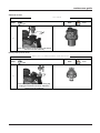
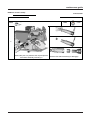
Checking the minimum power
1. To check the minimum power level, loosen screw “2” (Fig. b) and
insert the pressure gauge connection pipe as above.
2. Disconnect the air chamber compensation tube.
3. Switch the boiler on at maximum power, enabling the “flue
sweep” function (press the
button for 10 seconds; the
display shows “t -- “); press the programming key - to activate
operation at the minimum hot water power level. The display
will show “t __ “.
Disconnect a wire from the modulator (fig. d); the supply
pressure should correspond to the value shown in the “Gas
Settings” table, in relation to the type of gas for which the
boiler is designed. If it does not correspond, tighten or loosen
the adjustment screw “4” (fig. d) to adjust.
4. When the check is over, tighten screw “2” and make sure it is
securely in place.
5. Reconnect the modulator wire.
6. Reconnect the compensation tube.
7. The “flue sweep function” is automatically deactivated after 10
minutes or when the
button is pressed.
2
(c)
3
(d)
4
Check all test nipples for tightness when all checks are
complete.
29
commissioning
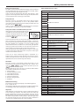
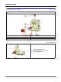
Accessing the settings and adjustment menus
menu 2 - Boiler parameters
submenu 3 - parameter 1
Maximum Heating Power adjustment
submenu 2 - parameter 0
Soft light Ignition
submenu 3 - parameter 5 and 6
Heating ignition delay
sottomenu 3 - parametro 0
Maximum Absolute Heating Power
(This parameter must be changed only to change gas or
replace P.C.B.)
PROGRAMMING
BUTTON
MENU/OK
BUTTON
The information relating to the menus and the individual
parameters are indicated on the display.
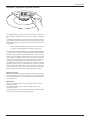
To access Menu 2, open the cover and proceed as follows:
1. Press the MENU/OK button; the first figure 000 will flash on
the display.
2. Press the “+” button to select menu “2
200”
3. Press the MENU/OK button; the second figur on the display will
10” will be requested.
flash and the access code “21
Caution! The menus reserved for qualified technicians may
only be accessed after setting the access code.
4. Press the MENU/OK button; 222 will appear on the display unit.
234.
5. Press the “+” button to select code 234
6. Press the MENU/OK button to select the sub menu; the second
20” will flash.
figure “22
7. Press the “+” button to select the sub menu, for example:
30”.
“23
8. Press the MENU/OK button to access the sub menu parameters;
0” will flash.
the third figure “230
9. Turn the encoder to select the parameter; the text on the
display will indicate the title of the pre-selected parameter
1 - Max. Adjustable Heating Power Level”.
“231
10. Press the “+” or “-” button to access the parameter; the display
will indicate the value, e.g “76”.
Note: The parameter value will be displayed for 20 seconds,
then will begin to flash in alternation with the parameter, e.g.
70 > 231
231”.
“70
11. Press the “+” or “-” button to select the new value, e.g. “75”.
12. Press MENU/OK to save the change or press ESC to exit without
saving.
To exit, press the ESC button until the normal display screen is
restored.
30
Maximum Heating Power adjustment
The maximum heating power can be adjusted to between the
maximum power (shown on the display as “99”, ) allowed by the
boiler and the minimum power (shown on the display as “0”, ).
To check the maximum heating power, access menu 2/sub menu
3/parameter 1, check the value and, if necessary, modify it as
indicated in the Heating Power Adjustment table.
Checking slow ignition power
The soft light can be adjusted between the maximum power
(shown on the display as “99”, ) and the minimum power (shown
on the display as “0”, ).
Change the parameter if the outlet pressure from the gas valve
in the ignition phase (measured when the boiler is in hot water
heating operation) does not coincide with the values shown in
the Gas Table:
To check the slow ignition power, access menu 2/sub menu 2/
parameter 0.
If needed, change the parameter value until suitable pressure is
achieved.
Heating ignition delay adjustment
This parameter – menu 2/sub menu 3/parameter 5 - can be used
to manually (0) or automatically (1) set the delay time before the
subsequent reignition of the burner after it has switched off on
reaching the desired temperature.
By selecting manual, it is possible to set the delay in minutes using
the successive parameter (menu 2/sub menu 3/parameter 6), to a
time between 0 and 7 minutes.
Automatic selection means that the boiler will establish the delay
time based on the set-point temperature.
Checking maximum absolute heating power
(ONLY IN CASE OF GAS CHANGE OR P.C.B. REPLACEMENT)
To check/modify the maximum absolute heating power, access
the gas valve and proceed as follows:
1. Loosen screw “2” (Fig. b) and insert the pressure gauge
connection pipe into the pipe tap.
2. Disconnect the air chamber compensation tube.
3. Switch the boiler on at maximum heating power, enabling the
“chimney sweep” function (press the
key for 5 seconds;
the display shows t --.
The supply pressure should correspond to the value shown in
the “Gas Settings” table according to the type of gas for which
the boiler is designed. If it does not correspond, access menu
2/sub menu 3/parameter 0 and press the + and - buttons to
modify the value until the pressure indicated in the Gas Table
has been reached.
4. When the check is complete, tighten screw “2” and make sure it
is securely in place.
5. The “chimney sweep” function is deactivated either automatically
after 10 minutes or when the ESC button is pressed.
commissioning
CLAS 30 FF
CLAS 24 FF
CLAS SYSTEM 28 FF CLAS SYSTEM 21 FF
Heating Power Adjustment
Gas
G20
G30
G31
Gas
G20
Heating Power (kW)
mbar
Parameter 2 3 1
mbar
Parameter 2 3 1
mbar
Parameter 2 3 1
Heating Power (kW)
mbar
Parameter 2 3 1
9,8 12,5 14,5 16,5 20,0 22,0 24,0
2,3
3,8
5,1
6,7
7,6
9,2 11,0
0
40
45
50
53
57
62
4,5
7,5 10,1 13,0 18,2 22,0 26,2
0
54
60
66
75
81
87
6,3 10,5 14,1 18,2 23,3 28,1 33,5
0
61
68
75
82
89
96
12,1 14
16
18
20
24
26
28
2,3
3,4
4,4
5,5
6,8
8,9 10,4 12,1
0
36
41
45
49
57
61
64
G30
mbar
5,1
7,4
9,7
12,3
15,2
19,1
22,4
26,0
G31
Parameter 2 3 1
mbar
Parameter 2 3 1
0
6,2
0
51
9,0
54
57
11,8
61
62
14,9
67
69
18,4
73
76
24,4
83
81
28,6
89
84
33,2
95
Gas Table
lower Wobbe index (15°C, 1013 mbar) (MJ/m3)
Gas Inlet Pressure
CLAS 24 FF
CLAS 30 FF
CLAS 21 FF SYSTEM
CLAS 28 FF SYSTEM
G20
G30
45.67
80.58
G31
(propane)
70.69
G20
G30
45.67
80.58
G31
(propane)
70.69
20
28/30
37
20
28/30
37
maximum D.H.W.
12,2
27,7
35,5
12,9
27,7
35,8
maximum heating (absolute)
(Menu 2/ submenu 3/ parameter 0)
11
(62)
26,2
(87)
33,5
(96)
12,2
(64)
26,0
(85)
33,5
(95)
minimum
2,3
4,5
6,3
2,3
5,1
6,0
Soft light
mbar
(Menu 2/ sub menu 2/ parameter 0)
5,0
(51)
11,2
(63)
11,2
(63)
5,49
(47)
9,51
(58)
9,51
(58)
Maximum heating power adjustment
(Menu 2/sub menu 3/ parameter 1)
46
66
66
49
66
71
Gas Burner
Pressure (mbar)
Ignition delay
(Menu 2/ sub menu 3/ parameter 5)
automatic
automatic
13
13
Main Burner jets nr.
Main Burner jets Ø
Max/min
consumption
(15°C, 1013 mbar)
(G.N.= m3/h) (GPL =
Kg/h)
1,25
0,75
0,75
1,32
0,8
0,8
maximum D.H.W.
2,86
2,13
2,10
3,31
2,47
2,43
maximum heating (absolute)
2,73
2,03
2,00
3,17
2,37
2,33
minimum
1,16
0,87
0,85
1,38
1,03
1,01
Gas changeover
The boiler can be converted to use either methane (natural) gas
(G20) or L.P.G. (G30 - G31) by an Authorised Service Centre.
The operations that must be performed are the following:
1. switch off the the electrical supply to the appliance
2. turn off the gas cock
3. disconnect the electrical connections to the boiler
4. gain access to the combustion chamber, as indicated in the
paragraph “Maintenance Guide - General Access”
5. replace the jets and attach the labels as directed in the instruction sheet for the Kit.
6. check that all connections are gas-tight
7. start up the boiler
8. perform the gas adjustment (see the paragraph “Checking the
gas setting”)
- maximum - hot water
- minimum
- maximum absolute heating power
- maximum Heating Power adjustment
- oft-light feature
- ignition delay feature for the heating system
9. carry out combustion analysis.
31
commissioning
Auto function
This is a function which enables the boiler to automatically adapt
its operation routine (the temperature of the radiators) in line
with the outdoor conditions, in order to achieve and maintain the
requested room temperature conditions.
Depending on the peripheral units connected and the number
of zones controlled, the boiler adjusts its flow temperature
automatically.
The various corresponding parameters should therefore be set
(see adjustments menu).
To activate the function, press the AUTO button
.
Example 1:
SINGLE ZONE SYSTEM (HIGH-TEMPERATURE) WITH ON/OFF ROOM THERMOSTAT:
In this case the following parameters must be set:
4 21 - Activation of temperature adjustment using sensors
- Select 01 = Basic temperature adjustment
2 44 - Boost Time (optional)
The wait time for the flow temperature increase in steps of
4°C may be set. The value varies according to the type of
system and installation.
If the Boost Time value = 00 the function is not activated.
Example 2:
SINGLE ZONE SYSTEM (HIGH-TEMPERATURE) WITH ON/OFF ROOM THERMOSTAT +
OUTDOOR SENSOR:
In this case the following parameters must be set:
4 21 - Activation of temperature adjustment using sensors
- Select 03 = outdoor sensor only
4 22 - Temperature adjustment curve selection (see page 39)
- Select the relevant curve according to the type of
system, installation, heat insulation used in the building,
etc.
4 23 - Perform a parallel curve shift if necessary, increasing or
decreasing the set-point temperature (this may also be
modified by the user, using the heating temperature
adjustment knob, which, with the Auto function
activated, is used to shift the curve in a parallel manner).
32
Example 3:
SINGLE ZONE SYSTEM (HIGH-TEMPERATURE) WITH REMOCON REMOTE CONTROL +
OUTDOOR SENSOR
In this case the following parameters must be set:
4 21 - Activation of temperature adjustment using sensors
- select 04 = outdoor sensor + room sensor
4 22 - Temperature adjustment curve selection (see page 39)
- Select the relevant curve according to the type of
system, installation, heat insulation used in the building,
etc
4 23 - Perform a parallel curve shift if necessary, increasing or
decreasing the set-point temperature. (This may also be
changed by the user by the encoder which, with the Auto
function activated, is used to shift the curve in a parallel
manner.)
4 24 - Influence of room sensor
- used to adjust the influence the room temperature has
on the calculation of the set-point flow temperature (20 =
maximum, 0 = minimum).
boiler protection devices
Safety shut-off
This type of error is “non-volatile”, which means that the boiler
starts up again automatically as soon as the problem which
caused the shut-off is removed; on the display and flash “Err” and
the error code (es: Err / 101
101).
In fact, as soon as the cause of the shut-off disappears, the boiler
starts up again and continues to operate normally.
Safety shut-off due to insufficient water pressure
If the water pressure inside the heating circuit
is insufficient, the boiler will perform a safety
shut-off. The display will flash “Err” and the
code for Insufficient circulation 103, 104, 105,
106 or 107 (Err
Err/107
107))
Check the water pressure on the pressure gauge and make sure
that is between 0.6 and1.5 bar when the system is cold. If the
pressure is just under the minimum refill the system by connecting
the silver flexible hose supplied to the two isolating points
underneath the boiler, once the hose is connected, open up both
of the grey quarter turn handles, once the pressure reads 1.5 bar
on the display, close both handles and disconnect the hose .
If the pressure drops very frequently, there may be a water leak
at some point in the system. If this is the case please contact your
installer and ask them to check it.
In this case or if the re-balancing request is performed on a
frequent basis, switch the boiler off, bring the external electric
switch to the OFF position, shut off the gas valve and contact a
qualified technician to check for any leaks of water.
Shutdown
This type of error is “non-volatile”, which means that it is not
removed automatically. On the display flash “Err” and the error
code (es: Err / 501
501).To restore normal operation press the
button on the control panel.
The first figure of the error code (e.g. 1 01) indicates within which
operational assembly the error occurred.
1 - Primary Circuit
2 - Domestic Hot Water Circuit
3 - Internal Electronic Part
4 - External Electronic Part
5 - Ignition and Detection
6 - Air inlet - flue gas outlet
7 - Multizone
Malfunction warning
This warning is shown by the display in the following format:
5 P3 = Flame cut-off
the first figure indicating the operational assembly is followed by
a P (warning) and the code relating to the specific warning.
Important
If this shutdown occurs frequently, contact an authorised Technical
Service Centre for assistance. For safety reasons, the boiler will
permit a maximum of 5 resets in 15 minutes (5 presses of the
RESET button); at the 6th attempt within this 15-minute period
the boiler will shut down and may only be operated again after
the electricity supply has been disconnected. If the shutdown is
occasional or an isolated event, this is not a problem.
Table summarising error codes
Central Heating circuit
Display
Description
1 01
Overheat
1 02
Pressure Sensor Error
1 03
1 04
1 05
Insufficient circulation
1 06
1 07
1 10
C.H. Flow temp. probe circuit open / short circuit
1 12
C.H. Return temp. probe circuit open / short circuit
1 14
External sensor circuit open / short circuit
1 P1
1 P2
Insufficient circulation indication
1 P3
D.H.W. circuit
2 01
2 02
D.H.W. temp. probe circuit open / short circuit
Circuito aperto o cortocircuito sonda
accumulo bassa
2 04
Circuito aperto o cortocircuito sonda
collettore solare
2 07
Sovratemperatura collettore solare
2 08
Intervento antigelo collettore solare
Internal P.C.B.’s
Kit solare
(optional)
Boiler protection devices
The boiler is protected from malfunctioning by means of internal
checks performed by the electronic microprocessor P.C.B., which
stops the boiler from operating if necessary.
In the event of the boiler being shut off in this manner, a code
appears on the display which refers to the type of shut-off and the
reason behind it. There are two types of shut-off :
3 01
EEPROM error
3 02
Communication error
3 03
Main P.C.B. error
3 05
Main P.C.B. error
3 06
Main P.C.B. error
3 07
Main P.C.B. error
External P.C.B.’s
4 07
Room sensor circuit open short circuit
Ignition and Detection
5 01
No flame detected
5 02
Flame detected with gas valve closed
5 P4
3 flame cut-offs detected in one cycle
Air Inlet / Flue gas outlet
6 04
Insufficient fan speed
6 07
Air pressure switch closed permanently
6 P1
Delay in air pressure switch closing
6 P2
APS close-open
Multizone (optional)
7 01
Zone2 Send Probe Damaged
7 02
Zone2 Return Probe Damaged
7 03
Zone3 Send Probe Damaged
7 04
Zone3 Return Probe Damaged
7 05
Hydraucic Comp. Probe Damaged
7 06
Zone2 Overheat
7 07
Zone3 Overheat
33
boiler protection devices
Anti-frost Device.
The anti-frost function acts on the central heating flow temperature probe, independently from other regulations, when the electrical supply is turned on.
If the primary circuit temperature falls below 8°C the pump will
run for 2 minutes.
After the two minutes of circulation (fixed) the boiler will check
the following:
a) if the central heating flow temperature is > 8°C, the pump
stops;
b) if the primary flow temperature is between 4 and 8°C, the pump
will run for another two minutes;
c) if the primary flow temperature is < 4°C, the burner will fire (heating position) at minimum power until the temperature reaches
33°C, the burner will go out and the pump will continue to run
for two minutes.
If the flow temperature remains between 4-8°C the pump will continue to run for two minutes for a maximum of 10 times unless a
temperature above 8°C is detected in the primary flow, after this
the the burner will fire.
If lockout is caused by overheat the burner is kept OFF.
Note: In all cases, the circulation takes place in the central heating
system.
The anti-frost device activates only when (with the boiler operating correctly):
- the system pressure is correct;
- the boiler is electrically powered;
- there is a supply of gas.
Combustion Analysis
The flue connector has two apertures, readings can be taken
for the temperature of the combustion by-products and of the
combustion air, as well as of the concentrations of O2 and CO2,
etc.
To access these intakes it is necessary to unscrew the front screw
and remove the metal plate with sealing gasket.
It is possible to activate the flue test mode by pressing and holding
the
button for 10 seconds.
The boiler will return to normal operation after 10 minutes. The
boiler can be returned to normal operation sooner by switching
the boiler off and on again.
When you have finished, reposition the metal plate correctly and
make sure the seal fits perfectly.
34
Flue test mode
The P.C.B. enables the boiler to be forced to its maximum or
minimum power.
By activating the Flue test mode, (pressing the
button for
10 seconds), the boiler will be forced to its maximum heating
power and the display shows:
To select operation at maximum power, press the “+” button and
the following will appear on the display:
To select operation at minimum power, press the “-” button and
the following will appear on the display:
This function is de-activated automatically after 10 minutes, or
when the ESC button is pressed.
Note: The boiler can also be forced to its maximum and minimum
power by accessing menu 7 (see settings - adjustment - problem
identification menu paragraph).
Product of Combustion
Discharge Monitoring
In the boiler, it is possible to monitor the correct operation of the
flue exhaust/air intake, checking for a loss of general pressure in the
system. Through the use of a differential manometer connected to
the test points of the combustion chamber, it is possible to detect
the ∆P of operation of the air pressure switch.
The value detected should not be less than 0.46 mbar (24/21 FF)
- 0.70 mbar (28/32 FF) under conditions of maximum thermal
power in order for the boiler to function properly and without
interruption.
settings - adjustment - problem identification menus
Accessing the settings - adjustment - problem identification
menus
The boiler can be used to manage the heating and domestic hot
water production system in its entirety.
Navigation within the menus enables the boiler system +
connected peripheral units to be customised, optimising
operation for maximum comfort and maximum saving. It also
provides important information relating to the efficient operation
of the boiler.
The parameters relating to each individual menu are listed in the
following pages.
The various parameters can be accessed and modified using th MENU/
OK button and the +/- buttons (see fig. below). The code of the menus
and of each individual parameter will be shown on the display.
The available menus are as follows:
2
Boiler Parameter
2
1
Service code (access reserved for qualified engineers)
PROGRAMMING
2
2
General setting
BUTTON
2
3
C.H. Parameters - Part 1
2
4
C.H. Parameters - Part 1
2
5
Domestic Hot Water (Combi only)
2
9
Menu 2 Reset to factory setting
3
Solar & Storage
3
0
General setting
3
1
Service code (access reserved for qualified engineers)
3
2
Special setting
4
Zone 1 Parameters
4
0
Set-point Zone1
4
1
Service code (access reserved for qualified engineers)
4
2
Zone 1 Setting
4
3
Diagnostics
4
4
Zone device mangement
5
Zone 2 Parameters
5
0
Set-point Zone2
5
1
Service code (access reserved for qualified engineers)
5
2
Zone 2 Setting
5
3
Diagnostics
5
4
Zone device mangement
5
5
Multizone
7
Test & Utilities
8
Service Parameter
8
1
Service code (access reserved for qualified engineers)
8
2
Boiler
8
3
Boiler Temperature
8
4
Solar & Storage
8
5
Service
8
6
Statistics
8
7
NOT ACTIVE
8
8
Error History
MENU/OK
BUTTON
The information relating to the menus and the individual parameters
are indicated on the display.
To access Menu 2, open the cover and proceed as follows:
1. Press the MENU/OK button; the first figure 000 will flash on the
display.
200”
2. Press the “+” button to select menu “2
3. Press the MENU/OK button; the second figur on the display will
10” will be requested.
flash and the access code “21
Caution! The menus reserved for qualified technicians may only
be accessed after setting the access code.
4. Press the MENU/OK button; 222 will appear on the display unit.
234.
5. Press the “+” button to select code 234
6. Press the MENU/OK button to select the sub menu; the second
20” will flash.
figure “22
7. Press the “+” button to select the sub menu, for example: “23
30”.
8. Press the MENU/OK button to access the sub menu parameters; the
0” will flash.
third figure “230
9. Press the +/- buttons to select the parameter; then press the
Menu/Ok button.
10. Press the “+” or “-” button to access the parameter; the display will
indicate the value, e.g “76”.
Note: The parameter value will be displayed for 20 seconds, then
will begin to flash in alternation with the parameter, e.g. “70
70 >
231”.
231
11. Press the “+” or “-” button to select the new value, e.g. “75”.
12. Press MENU/OK to save the change or press ESC to exit without
saving.
To exit, press the ESC button until the normal display screen is
restored.
35
sub-menu
2
BOILER PARAMETER
2
1
Service code
2
2
BOILER GENERAL SETTINGS
2
2
0
Soft ignition
from 0 to 90
see Gas Settings (pages 29 and 30)
2
2
1
Zone Frost Temperature (Room Temperature)
from 2 to 10
(°C)
only active when the BUS device is
connected
2
2
2
NOT PRESENT
2
2
3
NOT PRESENT
2
2
4
NOT PRESENT
2
2
5
Central Heating Start Delay
2
2
6
NOT PRESENT
2
2
7
NOT PRESENT
2
2
8
Boiler version - NOT TO MODIFY
Description
range
factory
setting
menu
parameter
settings - adjustment - problem identification menus
222
0=
1=
2=
3=
Disabled
10 seconds
90 seconds
210 seconds
from 0 to 5
0 = combi (CLAS)
1 = Storage with NTC
2 = Storage with Thermostat
(CLAS SYSTEM)
3 - 4 - 5 = DO NOT USE
Press +/- to select code 234 and press
MENU/OK
0
Active only with 2-zone p.c.b. (optional)
0
ONLY FOR SERVICE - To be used only in
substitution P.C.B.
2
2
3
CENTRAL HEATING PARAMETER - PART 1
2
3
0
Maximum Central Heating Aboslute power
from 0 to 99
ONLY FOR SERVICE - To be used only in
substitution P.C.B.
see Gas Settings (pages 29 and 30)
2
3
1
Maximum Central Heating power
Adjustable heating
from 0 to 99
see Gas Settings (pages 29 and 30)
2
3
2
NOT PRESENT
2
3
3
NOT PRESENT
2
3
4
NOT PRESENT
2
3
5
Anti-cycling time mode
0 = Manual
1 = automatic
0
2
3
6
Anti-cycling time
If 235 = 0
from 0 to 7 (minutes)
3
2
3
7
Central Heating pump overrun
from 0 to 15 (minutes)
o CO (continuos)
3
2
3
8
Pump speed control
0 = Low speed
1 = High speed
2 = Modulating
2
2
3
9
Set Delta T Pump
from 10 to 30 (°C)
20
see Gas Settings (pages 29 and 30)
Parameter to set if Pump Speed control
(238) is set to modulating
∆T (flow - return) for circulation pump modulation
This parameter can be used to set the difference between the flow and return temperatures, which determines the
commutation between low and high circulation pump speed.
E.g.: param. = 20 if the Tflow - Tret > 20°C; the circulation pump will be activated at maximum speed.
If the Tflow - Tret < 20 - 2°C; the circulation pump will be activated at minimum speed.
The minimum wait time between speed changes is 5 minutes.
36
sub-menu
parameter
2
4
CENTRAL HEATING PARAMETER - PART 1
2
4
0
NOT PRESENT
2
4
1
NOT PRESENT
2
4
2
NOT PRESENT
2
4
3
Post-ventilation after Central Heating
request
0 = OFF
1 = ON
2
4
4
Boost Time
from 0 to 60
(minutes)
Description
range
factory
setting
menu
settings - adjustment - problem identification menus
1
only enabled with Room Thermostat
on/off and temperature adjustment
activated (parameter 421 or 521 on
01 = Basic temperature adjustment)
This parameter can be used to set the delay time before the automatic increase in flow temperature, in steps of 4°C (max.
12°C). If the value of this parameter remains at 00 the function is not activated.
2
4
5
NOT PRESENT
2
2
4
4
6
7
NOT PRESENT
Central Heating Pressure
Detection Device
2
4
8
NOT PRESENT
2
5
DOMESTIC HOT WATER (COMBI)
2
5
0
COMFORT FUNCTION
(COMBI)
0 = Temperature Probes only
(COMBI)
1 = Pressure Switch (SYSTEM)
2 = Pressure Sensor
0
ONLY FOR SERVICE - To be used only in
substitution P.C.B.
0 = Disabled
1 = Time Based
2 = Always active
1
Time Based =Active for 30 minutes after a
D.H.W. request
The “COMFORT” function of the appliance can be used to increase the comfort level of the user when drawing hot water.
This function keeps the secondary exchanger hot during periods of boiler inactivity; this increases the initial heat
status of the water drawn, as the water is delivered at a higher temperature. Press the MENU/OK button to enable the
modification.
When the function is enabled the text COMFORT LED is illuminated.
This function may also be enabled or disabled by pressing the COMFORT button.
2
5
1
Comfort Anti-cycling Time (COMBI)
from 0 to 120 minutes
0
2
5
2
DHW Start Delay (COMBI)
From 5 to 200
(from 0,5 o 20 seconds)
5
2
5
3
D.H.W. switch logic (COMBI)
0 = Anti-scale (stop at > 67°C)
1 = At 4°C over set-point
2
5
4
Post-circulation and post-ventilation after
domestic hot water is drawn
0 = OFF
1 = ON
2
5
5
Delay start in Central Heating after D.H.W.
request
from 0 to 30 (minutes)
2
9
RESET MENU’ 2
2
9
0
3
BOILER WITH STORAGE (INSIDE OR OUTSIDE) AND BOILER WITH SOLAR KIT
3
0
GENERAL SETTINGS
3
0
0
Storage Setpoint Temperature - NOT ACTIVE
3
0
1
NOT ACTIVE
3
0
2
NOT ACTIVE
3
1
Service code
RESET MENU 2 Reset factory settings
ONLY FOR SERVICE - To be used only in
substitution P.C.B.
0
“Reset?OK=Yes, Esc=No”
For boiler with solar Kit connected
222
Press +/- to select code 234 and press
MENU/OK
37
sub-menu
parameter
3
2
SPECIAL SETTINGS
3
2
0
Anti-legionella Function - NOT ACTIVE
3
2
1
Solar Configuration Type
Description
factory
setting
menu
settings - adjustment - problem identification menus
range
Only for boiler with storage inside
0 = Nothing or single coil Natural
circulation
1 = Single coil Forced circulation
2 = Double coil
0
Select 1 or 2 only if the Solar Kit is
installed
3
2
2
Electrical Mixing valve
3
2
3
Collector Delta T pump ON
3
2
4
Collector Delta T pump OFF
3
2
5
Minimum Collector Temperature Pump ON
3
2
6
Kollectorkick
3
2
7
Recooling Function
3
2
8
Gas storage set point Delta
3
2
9
Collector Frost protection Temperature
4
ZONE 1 PARAMETERS
4
0
ZONE 1 SET TEMPERATURE
4
0
0
Set Day Temperature Zona 1
from 16 to 30 (°C)
19
4
0
1
Set Night Temperature Zona 1
from 16 to 30 (°C)
16
4
0
2
Fix temperature central heating
from 35 to85 (°C)
70
To set only with Fixed Flow Temperaure of
Thermoregulation (see 421)
4
1
Service code
222
Rotate encoder clockwise to select
code 234 and press MENU/OK
4
2
SET ZONE 1
4
2
0
Zone 1 Temperature range
DO NOT MODIFY
0= Low Temperature
1= High Temperature
4
2
1
Select Type of Thermoregulation
0 = Fixed Flow Temperature
1 = Basic Thermoregulation
2 = Room Temperature only
3 = Outdoor Temperature only
4 = Room + Outdoor
Temperature
4
2
2
Zone 1 Slope
1.0 - 1.5 = Standard System
2.0 - 3.5 = Convector Radiators
1
To enabled thermoregulation press Auto
button. The display show the symbol.
1_5
Only enabled when an outdoor sensor is installed
2.5
2.0
90
1.5
80
1.2
70
1.0
60
High temperature
alta tempertaura
3.5 3.0
°C 100
Flow Temperature
only active when the BUS device is
connected
ONLY FOR SERVICE
Active only with MGZ/MCM Kit
from 0_2 to 3_5
temperatura di mandata all’impianto
When an outdoor sensor is used, the boiler
calculates the most suitable delivery
temperature, taking into account the
outside temperature and type of system.
The type of curve should be selected
in correspondence with the projected
temperature of the system and the
nature of the dispersions present in the
structure.
For high-temperature systems, one of
the curves depicted in the chart may be
chosen.
Only with Solar Kit is installed
50
40
30
Note: The Outdoor Sensor should only be
used when the boiler is used for central heating
only.
38
10
5
0
-5
-10
-15
temperatura
esterna
External
temperature
-20 °C
sub-menu
parameter
Description
4
2
3
Parallel curve shift Zone 1 Offset
range
from - 20 to + 20
factory
setting
menu
settings - adjustment - problem identification menus
0
To adapt the heating curve to the system requirements, shift the curve in parallel so that the calculated flow temperature
is modified, in addition to the room temperature.
By accessing this parameter and turning knob “5” (Figs 1 and 2 - page 4), the curve can be shifted in a parallel manner.
The value is indicated on the display, from -20 to +20.
4
2
4
Room sensor Influence to calculate the
set-point temperature - Thermoregulation
enabled-
from 0 to 20
20
If set to = 0 the room temperature doesn’t influence the calculation of the set-point.
If set to = 20, the room temperature has the maximun influence to calculate the setpoint - only active when the BUS device is connected
4
2
5
Maximum Central Heating Temperature Zone1
from 40 to 82 (°C)
82
4
2
6
Minimum Central Heating Temperature Zone 1
from 40 to 82 (°C)
40
4
3
DIAGNOSTICS
4
3
0
Room Temperature Zone 1 - only active when the BUS device is connected
4
3
1
Flow Temperature Zone 1 - only active when the BUS device is connected
4
3
2
Zone 1 Heat Request
0 = OFF 1 =ON
4
3
3
Zone 1 Pump status
0 = OFF 1 =ON
Active only with MGZ/MCM Kit
4
4
ZONE 1 DEVICES
4
4
0
0 = OFF 1 =ON
Active only with MGZ/MCM Kit
5
ZONE 2 PARAMETER
5
0
ZONE 2 SET TEMPERATURE
5
0
0
Set Day Temperature Zona 2
from 16 to 30 (°C)
19
5
0
1
Set Night Temperature Zona 2
from 16 to 30 (°C)
16
5
0
2
Fix temperature central heating
from 35 to85 (°C)
70
To set only with Fixed Flow Temperaure of
Thermoregulation (see 521)
5
1
Service code
222
Press +/- to select code 234 and press
MENU/OK
5
2
SET ZONE 2
5
2
0
Zone 2 Temperature range
DO NOT MODIFY
0= Low Temperature
1= High Temperature
5
2
1
Select Type of Thermoregulation
0 = Fixed Flow Temperature
1 = Basic Thermoregulation
2 = Room Temperature only
3 = Outdoor Temperature only
4 = Room + Outdoor
Temperature
5
2
2
Zone 1 Slope
Zone 1 Pump control
from 0_2 to 3_5
only active when the BUS device is
connected
ONLY FOR SERVICE
Active only with MGZ/MCM Kit
1
To enabled thermoregulation press Auto
button. The display show the symbol.
1_5
Only enabled when an outdoor sensor is installed
When an outdoor sensor is used, the boiler calculates the most suitable delivery see graph previous page
prameter 4 2 2
temperature, taking into account the outside temperature and type of system.
The type of curve should be selected in correspondence with the projected
temperature of the system and the nature of the dispersions present in the
structure. For high-temperature systems, one of the curves depicted in the chart
may be chosen.
1.0 - 1.5 = Standard System
2.0 - 3.5 = Convector Radiators
Note: The Outdoor Sensor should only be used when the boiler is used for central heating only.
39
sub-menu
parameter
Description
5
2
3
Parallel curve shift Zone 2 Offset
range
from - 20 to + 20
factory
setting
menu
settings - adjustment - problem identification menus
0
To adapt the heating curve to the system requirements, shift the curve in parallel so that the calculated flow temperature
is modified, in addition to the room temperature.
By accessing this parameter and turning knob “5” (Figs 1 and 2 - page 4), the curve can be shifted in a parallel manner.
The value is indicated on the display, from -20 to +20.
5
2
4
Room sensor Influence to calculate the
set-point temperature - Thermoregulation
enabled-
from 0 to 20
20
If setted = 0 the room temperature doesn’t influence the calculation of the set-point.
If setted = 20, the room temperature has the maximun influence to calculate the setpoint - only active when the BUS device is connected
5
2
5
Maximum Central Heating Temperature Zone2
from 40 to 82 (°C)
82
5
2
6
Minimum Central Heating Temperature Zone 2
from 40 to 82 (°C)
40
5
3
DIAGNOSTICS
display only
5
3
0
Room Temperature Zone 2 - only active when the BUS device is connected
5
3
1
Flow Temperature Zone 2 - only active with MGZ/MCM Kit
5
3
2
Return Temperature Zone 2 - only active with MGZ/MCM Kit
5
3
3
Set Temperature Zone 2 -only active when the BUS device is connected
5
3
4
Heat Request Zone 2
0 = OFF 1 = ON
5
3
4
Pump Status Zone 2
0 = OFF 1 = ON
5
4
ZONE2 DEVICES
5
4
0
Operation Mode Test
0 = OFF
1 = ON
2 = Manual
5
4
1
Valve control
0 = OFF
1 = Open
2 = Closed
5
4
2
Pump control
0 = OFF - 1 = ON
5
5
MULTIZONE
5
5
0
Hydraulic Compensator T
from 0 to 120 (°C)
0
5
5
1
Flow T Offset
from 0 to 40 (°C)
5
7
TEST & UTILITIES
7
0
0
Test Mode
rotate the enoder to select the different test
mode
t -- = Max Heating power
t -t -- = Max DHW power (COMBI)
t -- = Minimum power
7
0
1
Air purge Function
Press Menu/Ok button to active
8
SERVICE PARAMETERS
8
1
Service code
8
2
BOILER
8
2
0
Modulation Rate
from 0 to 165 MA
8
2
1
Fan Status
0 = OFF 1 = ON
8
2
2
NOT ACTIVE
8
2
3
Pump speed
0= Low speed 1 = High speed
8
2
4
Diverter valve position (COMBI)
0 = D.H.W. 1 =Central Heating
8
2
5
D.H.W. Flow Rate (l/min) (COMBI)
8
2
6
Air Pressure Switch Status
40
only active with MGZ/MCM Kit
only active with MGZ/MCM Kit
222
0 = Open 1 = Closed
only active with MGZ/MCM Kit
Enabled also by pressing for 10 seconds
the Reset button. This function is
deactivated automatically after 10
minutes, or when the ESC button is
pressed.
Press +/- to select code 234 and press
MENU/OK
sub-menu
parameter
8
3
BOILER TEMPERTURE
8
3
0
Set temperature Central Heating(°C)
8
3
1
Flow Heating temperature (°C)
8
3
2
Return Heating temperature (°C)
8
3
3
Domestic Hot Water Temperature (°) (COMBI)
8
4
SOLAR & STORAGE
8
4
0
Storage Temperature (°)
8
4
1
Solar collector Temperature
8
4
2
D.H.W. Inlet Temperature
8
4
3
NTC Storage Low
8
4
4
Storage Set-point stratification
8
4
5
Solar pump run time
8
4
6
Collector overheat Temp Time
8
5
SERVICE
8
5
4
P.C.B Hardware version
8
5
5
P.C.B Software version
8
5
6
P.C.B BUS Software version
8
6
STATISTICS
8
6
0
Hours Burner On (Central Heating) (h/10)
8
6
1
Hours Burner On (Domestic Hot Water) (h/10)
8
6
2
Number of Flame Faults (nr/10)
8
6
3
Number of ignition Cycles (nr/10)
8
6
4
NOT PRESENT
8
6
5
Heat request Duration
8
7
NOT ACTIVE
8
8
ERROR HISTORY
8
8
0
Description
Last 10 errors
range
factory
setting
menu
settings - adjustment - problem identification menus
Displayed only with Solar Kit or
external storage Kit
from E00 to E99
This parameter makes it possible to see the last 10 errors shown by the boiler as well as the relevant day, month and year.
Access the parameter to bring up the sequence of errors from number E00 to number E99.
The following data is shown in a sequence for each single error:
E -0
- error number
1 08
- error code
8
8
1
Reset Error List
Reset? Ok=Yes Esc=No
41
maintenance
Important
Maintenance is an essential part of the safe and efficient operation
of the boiler and ensures its durability. It should be performed
according to the instructions given in current legislation. Perform
combustion analysis regularly in order to check the operating
efficiency of the boiler and to make sure any polluting substances
relased are within the boudaries set by current legislation.
Before beginning maintenance work:
- Disconnect the appliance from the electricity supply by
turning the external bipolar switch to the “OFF” position;
- Close the gas valve and the central heating and domestic hot
water system valve.
After the work has been completed the initial settings will be
restored.
General comments
It is recommended that the following inspections be carried out
on the boiler at least once a year:
1. Check the seals in the water part and, if necessary, replace the
gaskets and restore the seal to perfect working order.
2. Check the seals in the gas part and, if necessary, replace the
gaskets and restore the seal to perfect working order.
3. Visually check the overall condition of the boiler.
4. Visually check the combustion and, if necessary, disassemble
and clean the burner.
5. Following the inspection detailed in point “3”, disassemble
and clean the combustion chamber, if necessary.
6. Following the inspection detailed in point “4”, disassemble
and clean the burner and injector, if necessary.
7. Cleaning the primary heat exchanger
8. Make sure the following heating safety devices are operating
correctly:
- temperature limit safety device.
9. Make sure that the following gas part safety devices are
operating correctly:
- absence of gas or flame safety device (ionisation).
10. Check the efficiency of the domestic hot water production
process (test the flow rate and temperature).
11. Perform a general inspection of the boiler operation.
12. Remove oxide from the detection electrode using an emery
cloth.
Operational test
After having carried out the maintenance operations, fill the
heating circuit at a pressure of approximately 1.0 bar and release
the air from the system.
Fill the domestic hot water system at the same time.
- Begin operating the boiler.
- If necessary, release the air from the heating system again.
- Check the settings and make sure all the command, adjustment
and monitoring parts are working correctly.
- Check the seal and that the system for the expulsion of fumes/
suction of comburent air is operating correctly.
Draining procedures
The heating system must be drained using the following
procedure:
- Switch off the boiler, make sure the external bipolar switch is in
the OFF position and shut off the gas valve;
- Loosen the automatic air relief valve;
- Open the system discharge valve and collect the escaping water
in a container;
- Empty the water from the lowest points of the system (where
applicable).
If the system is to be left inactive in areas where the room
temperature may fall below 0°C during winter, we recommend
that anti-freeze liquid is added to the water in the heating system
in order to avoid the need for repeated draining; when this liquid
is used make sure it is compatible with the stainless steel used for
the bodywork of the boiler.
We recommend the use of anti-freeze products which contain
PROPYLENE GLYCOLS as these inhibit corrosion and that they
are used in conjunction with the anti-scaling and anti-corrosion
function, in the quantities suggested by the manufacturer, at the
mimimum temperature.
Regularly check the pH level of the water/anti-freeze mix in the
boiler circuit and replace it when the value measured is lower than
the limit prescribed by the manufacturer.
DO NOT MIX DIFFERENT TYPES OF ANTI-FREEZE.
The manufacturer will not be held liable for any damage caused
by the appliance or the system due to the use of inappropriate
anti-freeze substances or additives.
Draining the domestic hot water system and indirect cylinder
Every time there is a danger of freezing, the domestic hot water
system must be drained as follows:
- Shut off the water mains inlet valve;
- Open all the hot and cold water taps;
- Empty the water from the lowest points of the system (where
applicable).
WARNING
Before handling, empty all components which may contain hot
water, performing bleeding where necessary.
Descale the components in accordance with the instructions
provided on the safety data leaflet supplied with the product used,
make sure the room is well ventilated, wear protective clothing,
avoid mixing different products, and protect the appliance and
surrounding objects.
Seal all openings used to take a gas pressure reading or to make
any gas adjustments.
Make sure that the nozzle is compatible with the supplied gas.
If a smell of burning is detected or smoke is seen leaking from
the appliance, or there is a smell of gas, disconnect it from the
electricity supply, shut off the gas valve, open the windows and
call for technical assistance.
42
maintenance
Draining the System
Draining the Heating System
The heating system must be drained as follows:
- Turn off the boiler;
- Attach a hose pipe and open the drain valve;
- Drain the system at the lowest points (where present). When
the heating system is unused for an extended period of time, it
is recommended that you add antifreeze with an ethylene glycol
base to the water in the heating pipe work and radiators if the
ambient temperature drops below 0°C during the winter.
This makes repeated draining of the entire system unnecessary.
Draining the Domestic Hot Water System
Whenever there is the danger of the temperature dropping below
the freezing point, the domestic hot water system must be drained
as follows:
- Turn off the general water valve for the household plumbing
system;
- Turn on all the hot water taps;
- Empty the remaining water from the lowest points in the
system (where present).
Completion
For the Republic of Ireland it is necessary to complete a “Declaration
of Conformity” to indicate compliance to I.S. 813. An example
of this is given in the current edtion of I.S. 813. In addition it is
necessary to complete the Benchmark Log Book.
Operational Checks
1. The flue system must be visibly checked for soundness.
2. On Central Heating allow the system to warm up and
manipulate the Central Heating temperature control knob,
check the burner modulates up and down between the high
and low settings.
3. Range rate the thermal power for Central Heating, as detailed
on page 30.
4. Run the Domestic Hot Water, manipulate the Domestic
Hot Water temperature control knob to check the burner
modulates up and down between the high and low settings
(COMBI only).
5. Balance the Central Heating system until all return
temperatures are correct and equal.
6. Switch ON/OFF button OFF, disconnect the pressure Gauge,
retighten screw and relight boiler.
7. Re-examine Central Heating, Domestic Hot Water and Cold
Water supplies for soundness.
8. Check the appearance of the gas flame to assess the adequacy
of the combustion air supply.
9. If external controls have been disconnected, reconnect and
test.
10. Refit boiler casing.
11. Complete the Benchmark Commisssioning Checklist on page
46 and any other necessary documentation.
Instructing The End User
1. Hand over the copy of the End User Instructions supplied with
the appliance, together with these instructions, and explain
how to use the timeclock and room thermostat if fitted.
2. Show the End User how to switch the appliance off quickly, and
indicate the position of the electric supply isolator.
3. Inform the End User of the location of all drains, isolating valves
and air vents.
4. Explain how to turn the appliance off for both short and long
periods and advise on the precautions necessary to prevent
damage in the event that the appliance is inoperative when
freezing conditions occur.
5. Finally advise the End User that, for continued safe and efficient
operation, the appliance must be serviced by a competent
person at least once a year.
It is recommended that the following inspections be carried out
on the boiler at least once a year:
1Check the seals for the water connections; replace any
faulty seals.
2Check the gas seals; replace any faulty gas seals.
3Visual check of the entire unit.
4Visual check of the combustion process or analysis of
combustion by-products (see Section 3.4) and cleaning of
the burner if needed.
5If necessary, dismantling and cleaning of the combustion
chamber.
6If necessary, dismantling and cleaning of the burner jets.
7Visual check of the primary heat exchanger:
- check for overheating in the blade assembly;
- clean the exhaust fan if needed.
8Adjustment of the gas pressure, gas rate and soft-light,
partial load and full load.
9Check of the heating safety systems:
- safety device for maximum temperature (overheat
thermostat);
- safety device for maximum pressure (safety valve).
10Check of the gas safety systems:
- safety device for lack of gas or flame ionisation (detection
electrode).
11Check of the electrical connection (ensure it complies with
the instructions in the manual).
12Check of Domestic Hot Water production efficiency (flow
rate and temperature)
13General check of the combustion by-products of the
discharge/ventilation system.
14Check of the general performance of the unit.
43
maintenance guide
General access
GENERAL ACCESS
Tools
Time
3 min
1
Unclip the cover to remove
Remove the two screws
Lower the electrical box
Remove the combustion chamber
front panel by releasing the clips
2
44
Remove the front panel
maintenance guide
Electrical Unit
Control Box access
CONTROL BOX ACCESS
Tools
Time
4 min
1
Remove the front panel as above
and pivot the electrical box
Fuse2.2
Unlock the four clamps to gain
access to the control box
FUSE
FUSE
Tools
Time
5 min
1
Open the control box as above
Remove the fuse
45
maintenance guide
Main
2.3 PCB
MAIN PCB
MAIN PCB
Tools
Time
7 min
Time
7 min
1
After opening the control box,
disconnect the electrical plug
connectors
Unscrew the two screws and
remove the PCB
Display PCB
2.4 DISPLAY PCB
DISPLAY PCB
Tools
1
Unclip the cover to remove
2
Disconnect the electrical plug
connectors, unlock the four
clamps, and remove the PCB
46
Lower the door and remove the
two control knobs
Unscrew the four screws and
pull the assembly towards you
maintenance guide
Hydraulic Unit
Right
hydraulic
block
assembly BLOCK ASSEMBLY
3.1hand
RIGHT
HAND
HYDRAULIC
CLAS 24/30 FF
LEGEND
1.
Diverter valve motor
2.
Diverter valve
3.
Auto air vent
4.
Primary water pressure switch
5.
Pump
6.
Central heating filter
7.
Not applicable in UK
8.
Non-return valve
9.
Non-return valve assembly
10. DHW flow switch assembly
11. Central heating return
12. Cold water inlet (DHW)
13. Central heating drain valve
CLAS SYSTEM 21/28 FF
LEGEND
1.
Auto air vent
2.
Primary water pressure switch
3.
Pump
4.
Central heating filter
5.
Central heating return
6.
Central heating drain valve
47
maintenance guide
3 way
3.2 valve
3 WAY VALVE
CLAS 24/30 FF
3 WAY VALVE UNIT
Tools
Time
5 min
1
Unplug the diverter valve cable
Remove the clip and lift the motor from the
diverter valve body
Drain the boiler (see 3.3). Remove the clip and
lift the diverter valve from the assembly
When reassembling, ensure the diverter valve is
aligned correctly
2
Draining
3.3 DRAINING
DRAINING
Tools
Time
1
Turn the drain valve anti-clockwise to open and
drain the water from the boiler.
48
5 min
maintenance guide
Automatic
air vent
3.4 AUTOMATIC
AIR VENT
AUTOMATIC AIR VENT
Tools
Time
5 min
1
Drain boiler (see 3.3). Remove the clip and lift
the AAV from the assembly
Primary
pressur
sensor PRESSURE SENSOR
3.5 water
PRIMARY
WATER
PRIMARY WATER PRESSURE SENSOR
Tools
Time
5 min
1
Drain boiler (see 3.3). Remove the fixing clip,
unplug the electrical connector and lift the
sensor from the assembly
49
maintenance guide
Pump
3.6
PUMP
PUMP
Tools
Time
10 min
1
Drain boiler (see 3.3). Remove
the clip and the two screws
Disconnect the pipe and then
move the pump to the right
disengage
Remove the sensor (see 3.5)
Remove the AAV (see 3.4)
Remove the pump
2
CH3.7
Filter CH FILTER
CH FILTER
Tools
Time
1
Remove the clip
50
Remove the filter
5 min
maintenance guide
DHW Flow switch assembly
3.8 DHW FLOW SWITCH ASSEMBLY
CLAS 24/30 FF
DHW FLOW SWITCH ASSEMBLY
Tools
Time
5 min
1
Drain boiler (see 3.3). Remove the clip and pull the
flow switch assembly towards you
Twist the flow switch assembly to disengage
51
maintenance guide
Left hand hydraulic block assembly
3.9 LEFT HAND HYDRAULIC BLOCK ASSEMBLY
1. DHW temperature sensor
2. Left hand hydraulic block
3. By-pass assembly
CLAS 24/30 FF
4. Safety valve
5. Central heating flow
6. Domestic hot water outlet
CLAS SYSTEM 21/28 FF
1. Left hand hydraulic block
2. Safety valve & By-pass assembly
3. Central heating flow
52
maintenance guide
D.H.W. Temperature sensor
3.10 DHW TEMPERATURE SENSOR
CLAS 24/30 FF
DHW TEMPERATURE SENSOR
Tools
Time
5 min
1
Isolate the cold water supply
and drain the DHW circuit.
Unplug the DHW sensor and
remove the clip
Sensor without wire and clip
Lift the sensor from
the assembly
Safety
valve
3.11
SAFETY VALVE
SAFETY VALVE
Tools
Time
5 min
1
Drain boiler (see 3.3). Disconnect the
discharge pipe
Remove the first clip on the left and
pull the safety valve towards you
53
maintenance guide
By-pass assembly
3.12 BY-PASS ASSEMBLY
BY-PASS ASSEMBLY
Tools
Time
5 min
1
Drain boiler (see 3.3). Remove the
second clip and pull the assembly
towards you
Push on the by-pass to disengage it
Secondary heat exchanger
3.13 SECONDARY HEAT EXCHANGER
CLAS 24/30 FF
SECONDARY HEAT EXCHANGER
Tools
Time
1
Drain primary and domestic hot water circuits. Remove the two
screws and remove the heat exchanger
54
10 min
maintenance guide
Temperature sensors & overheat thermostat
3.14 TEMPERATURE SENSORS & OVERHEAT THERMOSTAT
TEMPERATURE SENSORS & OVERHEAT THERMOSTAT
Tools
Time
5 min
1
Remove the clips and the
temperature sensor or
overheat thermostat together
Unplug the electrical connectors
IMPORTANT!!!! Do not use conducting paste for the contact sensors because it will alter the resistance value.
TEMPERATURE (°C)
RESISTANCE (kOmh)
0
10
20
25
30
40
50
60
70
80
27
17
12
10
8
5
4
3
2
1,5
55
maintenance guide
Main
heatMAIN
exchanger
3.15
HEAT EXCHANGER
MAIN HEAT EXCHANGER
Tools
Time
15 min
1
Drain boiler (see 3.3). Remove
Remove the four pipes clips and
the two screws and pivot the
the overheat sensor
combustion chamber panel
2
Remove the two screws at the
top of the exchanger
56
Pull the heat exchanger towards
you
Remove the two pipes to free
the heat exchanger
maintenance guide
Burner
unit UNIT
4. BURNER
57
maintenance guide
Spark generator
4.1 SPARK GENERATOR
SPARK GENERATOR
Tools
Time
5 min
1
Disconnect electrically the
boiler and open the control
box
Free the wire by removing the
two screws
Unplug the ignition electrode
from the spark generator
Pull the spark generator
towards you after removing
the screw
Disconnect the spark generator
and the earth from the control box
2
Electrodes assembly
4.2 ELECTRODES ASSEMBLY
ELECTRODES
Tools
Time
1
Remove the combustion chamber
front panel and unplug the electrodes
58
Remove the screw and pull the
electrodes assembly towards you.
5 min
maintenance guide
Burner
4.3
BURNER
BURNER
Tools
Time
15 min
1
Isolate the gas supply.
Remove the electrodes as above
Remove the compensation
flexible pipe and the two screws
from the gas elbow
Remove the two screws from the
burner
Remove the four screws to free
the manifold
The burner
Pull the assembly towards
you
2
Manifold
4.4 MANIFOLD
MANIFOLD
Tools
Time
10 min
1
Isolate the gas supply.
Disconnect the electrodes as
above
Remove the compensation
flexible pipe and the two screws
from the gas elbow
Remove the four screws and pull
the assembly towards you
Pull down the gas elbow to
free the manifold
59
maintenance guide
Fan
4.5
FAN
FAN
Tools
Time
5 min
1
Disconnect the fan wires
Remove the air pressure switch support and the
condensate collector
2
Remove the four screws and pull the fan
towards you
Air pressure switch
4.6 AIR PRESSURE SWITCH
AIR PRESSURE SWITCH
Tools
Time
1
Disconnect the air
pressure switch wires
60
Disengage the air pressure switch by
unlock the four clamps and pivot it
towards you
4 min
maintenance guide
Gas valve
4.7 GAS VALVE
GAS VALVE
Tools
Time
15 min
1
Remove the screw to free the
spark generator and the
compensation flexible pipe
Remove the gas valve wires
Remove the screws to free the
gas valve assembly
Gas valve assembly
Remove the three screws to free
the gas inlet pipe
Remove the four screws to
free the gas part between the
gas valve and the manifold
2
61
maintenance guide
Annual
Maintenance
5. ANNUAL
MAINTENANCE
Plate heat exchanger
Maintenance Interval: As necessary
How: To measure specification of DHW performance.
By-pass & Safety valve
Maintenance Interval: Annually
How: Visual inspection / Clean as necessary
Central heating filter
Maintenance Interval: Annually
How: Visual inspection / Clean as necessary
Flow switch operation
Maintenance Interval: Annually
How: Visual inspection / Clean as necessary
/ Check flow rate
Expansion vessel
Maintenance Interval: Annually
How: Check air pressure is at 1 bar (System drained)
Ignition & detection electrodes
Maintenance Interval: Annually
How: Visual inspection / Clean as necessary / Distance from the
burner / Ionisation current more than 1 A
Burner
Maintenance Interval: Annually
How: Visual inspection / Clean as necessary
Fan
Maintenance Interval: Annually
How : Visual inspection / Clean as necessary
Primary Heat exchanger
Maintenance Interval: Annually
How : Visual inspection / Clean as necessary
Pump
Maintenance Interval: At the first ignition and annually
How: Check that the AAV is open /
Visual inspection / Clean as necessary
62
short list
208
113
216
206
327
150
135
107
110
401
444
589
537
601
576
632
630
619
603
606
638
701
705
Key N
Description
Manf. Pt.N
Type
24 28
0107 BURNER
0110 ELECTRODE (IGNITION/DETECTION)
0113 MAIN EXCHANGER
65104220
65104549
65104246
0135 THERMOSTAT
0206 FAN
FAN
0216 AIR PRESSURE SWITCH
AIR PRESSURE SWITCH
0327 EXPANSION VESSEL
65104500
65104357
65104452
65104671
65104672
65104261
0537 PRESSURE RELIEF VALVE
61312668
0576 TEMPERATURE PROBE + CLIP
0589 SECONDARY EXCHANGER
0601 MOTOR - THREE-WAY VALVE
990686
65104333
61302483
0603
0606
0619
0630
3-WAY SPRING KIT (D.H.W.)
SENSOR (REED)
PUMP
3-WAY SPRING KIT (D.H.W.)
65104314
65104323
65104227
65104317
0632
0638
0701
0705
0706
TEMPERATURE PROBE + CLIP
AUTO AIR VENT WITH O-RING
PRESSURE GAUGE
P.C.B. (MAIN)
PRINTED CIRCUIT BOARD (DISPLAY)
990686
65104703
65104234
65105068
65104448
FF
CL
SY AS
ST
EM
CL
AS
FF
706
21 28
30
...
..
..
.....
...
..
...
...
..
.....
.....
..
...
..
.. ...
...
..
..
..
..
.. ...
...
..
.. ...
..
...
...
..
.. ...
63
BENCHMARK No.
GAS BOILER COMMISSIONING CHECKLIST
BOILER SERIAL No.
NOTIFICATION No.
CONTROLS To comply with the Building Regulation, each section must have a tick in one or other of the boxes
TIME & TEMPERATURE CONTROL TO HEATING
ROOM T/STAT & PROGRAMMER/TIMER
PROGRAMMABLE ROOMSTAT
CYLINDER T/STAT & PROGRAMMER/TIMER
COMBI BOILER
HEATING ZONE VALVES
FITTED
NOT REQUIRED
HOT WATER ZONE VALVES
FITTED
NOT REQUIRED
THERMOSTATIC RADIATOR VALVES
FITTED
AUTOMATIC BYPASS TO SYSTEM
FITTED
TIME & TEMPERATURE CONTROL TO HOT WATER
NOT REQUIRED
FOR ALL BOILERS CONFIRM THE FOLLOWING
THE SYSTEM HAS BEEN FLUSHED IN ACCORDANCE WITH THE BOILER MANUFACTURER’S INSTRUCTIONS?
THE SYSTEM CLEANER USED
THE INHIBITOR USED
FOR THE CENTRAL HEATING MODE, MEASURE & RECORD
GAS RATE
m3/hr
ft3/hr
BURNER OPERATING PRESSURE ( IF APPLICABLE)
N/A
mbar
CENTRAL HEATING FLOW TEMPERATURE
°C
CENTRAL HEATING RETURN TEMPERATURE
°C
FOR COMBINATION BOILERS ONLY
HAS A WATER SCALE REDUCER BEEN FITTED?
YES
NO
WHAT TYPE OF SCALE REDUCER HAS BEEN FITTED
FOR THE DOMESTIC HOT WATER MODE, MEASURE & RECORD
GAS RATE
m3/hr
ft3/hr
MAXIMUM BURNER OPERATING PRESSURE (IF APPLICABLE)
N/A
mbar
COLD WATER INLET TEMPERATURE
°C
HOT WATER OUTLET TEMPERATURE
°C
WATER FLOW RATE
Its/min
FOR CONDENSING BOILERS ONLY CONFIRM THE FOLLOWING
THE CONDENSATE DRAIN HAS BEEN INSTALLED IN ACCORDANCE WITH
THE MANUFACTURER’S INSTRUCTIONS?
YES
FOR ALL INSTALLATIONS CONFIRM THE FOLLOWING
THE HEATING AND HOT WATER SYSTEM COMPLIES
WITH CURRENT BUILDING REGULATIONS
THE APPLIANCE AND ASSOCIATED EQUIPMENT HAS BEEN INSTALLED AND COMMISSIONED
IN ACCORDANCE WITH THE MANUFACTURER’S INSTRUCTIONS
IF REQUIRED BY THE MANUFACTURER, HAVE YOU RECORDED A CO/CO2 RATIO READING?
THE OPERATION OF THE APPLIANCE AND SYSTEM
CONTROLS HAVE BEEN DEMONSTRATED TO THE CUSTOMER
THE MANUFACTURER’S LITERATURE HAS BEEN LEFT WITH THE CUSTOMER
COMMISSIONING ENG’S NAME
N/A
PRINT
CORGI ID N°.
SIGN
DATE
YES
CO/CO2 RATIO
S E R V I C E I N T E R VA L R E C O R D
It is recommended that your heating system is serviced regularly
and that you complete the appropriate Service Interval Record Below.
Service Provider. Before completing the appropriate Service Interval Record below, please ensure you have carried out the service
SERVICE 1 DATE
SERVICE 2 DATE
ENGINEER NAME
COMPANY NAME
TEL No.
CORGI ID CARD SERIAL No.
COMMENTS
ENGINEER NAME
COMPANY NAME
TEL No.
CORGI ID CARD SERIAL No.
COMMENTS
SIGNATURE
SIGNATURE
SERVICE 3 DATE
SERVICE 4 DATE
ENGINEER NAME
COMPANY NAME
TEL No.
CORGI ID CARD SERIAL No.
COMMENTS
ENGINEER NAME
COMPANY NAME
TEL No.
CORGI ID CARD SERIAL No.
COMMENTS
SIGNATURE
SIGNATURE
SERVICE 5 DATE
SERVICE 6 DATE
ENGINEER NAME
COMPANY NAME
TEL No.
CORGI ID CARD SERIAL No.
COMMENTS
ENGINEER NAME
COMPANY NAME
TEL No.
CORGI ID CARD SERIAL No.
COMMENTS
SIGNATURE
SIGNATURE
SERVICE 7 DATE
SERVICE 8 DATE
ENGINEER NAME
COMPANY NAME
TEL No.
CORGI ID CARD SERIAL No.
COMMENTS
ENGINEER NAME
COMPANY NAME
TEL No.
CORGI ID CARD SERIAL No.
COMMENTS
SIGNATURE
SIGNATURE
SERVICE 9 DATE
SERVICE 10 DATE
ENGINEER NAME
COMPANY NAME
TEL No.
CORGI ID CARD SERIAL No.
COMMENTS
ENGINEER NAME
COMPANY NAME
TEL No.
CORGI ID CARD SERIAL No.
COMMENTS
SIGNATURE
SIGNATURE
as described in the boiler manufacturer’s instructions. Always use the manufacturer’s specified spare part when replacing all controls
MTS (GB) Limited
MTS Building
Hughenden Avenue
High Wycombe
Bucks HP13 5FT
Telephone: (01494) 755600
Fax: (01494) 459775
Internet: www.mtsgroup.com/uk
E-mail: info@uk.mtsgroup.com
Technical Advice: 0870 241 8180
Customer Service: 0870 600 9888
MTS Heating Limited
Damastown Industrial Park
Damastown Avenue
Mulhuddart
Dublin 15
Telephone: (01) 810 3723
Fax: (01) 810 3727
Internet: www.mtsgroup.com/ie
E-mail: info@ie.mtsgroup.com
Technical Advice: (01) 437 0121
Customer Service: (01) 437 0121
420010108501 - 09/2007
Commercial subsidiaries:
JhZgÉhbVcjVa
8A6H')$(%
8A6HHNHI:B '&$'L6AA=JC<<6H7D>A:G
INE:8
9B7I(*<<
9B7I)&<<
9B7IIOIJ;C('<<
9B7IIOIJ;C(.<<
<#8#C/
<#8#C/
),"&&+"*.')@L
),"&&+"+&(%@L
<#8#C/
<#8#C/
)&"&&+"','&@L
)&"&&+"'-'-@L
user’ manual
Dear Customer,
Thank you for choosing an ARISTON boiler.
We guarantee that your boiler is a reliable and
technically sound product.
This manual provides detailed instructions and
recommendations for proper installation,
use and maintenance.
Remember to keep this manual in a safe place
for future reference i.e. by the gas meter.
Your local MTS Servicing Centre is at your
complete disposal for all requirements.
GUARANTEE
The appliance is guaranteed for 24 months from the date of purchase.
Aristons only obligation under the guarantee will be to repair or replace the faulty appliacnce at Aristons discretion. This will be carried out
where the fault arises from within defects in the appliance, caused either
by material or workmanship of the manufacturer.
This guarantee does not protect malfunction or damage arising from
incorrect installation, commissioning or maintenance procedures as laid
out in the installation and servicing manual, inefficient flue system, poor
or incorrect electricicty, wrong gas supply or pressure, tampering by
inexperienced persons and any other cause not directly due to manufacture.
MTS (GB) Limited cannot accept responsibility for any cost arising from
repair or maintenance carried out by any third party.
The installation and first ignition of the boiler must be
performed by qualified personnel in compliance with current
national regulations regarding installation, and in conformity
with any requirements established by local authorities and
public health organisations.
After the boiler has been installed, the installer must ensure
that the end user receives the declaration of conformity and
the operating manual, and should provide all necessary
information as to how the boiler and the safety devices should
be handled.
This appliance is designed to produce hot water for domestic use.
It should be connected to a heating system and a distribution
network for domestic hot water, both of which must be compatible
with its performance and power levels.
The use of the appliance for purposes other than those specified is
strictly forbidden. The manufacturer cannot be held responsible for
any damage caused by improper, incorrect and unreasonable use
of the appliance or by the failure to comply with the instructions
given in this manual.
Installation, maintenance and all other interventions must be carried
out in full conformity with the governing legal regulations and the
instructions provided by the manufacturer. Incorrect installation
can harm persons, animals and possessions; the manufacturing
company shall not be held responsible for any damage caused as
a result.
In the event of any maintenance or other structural work in the
immediate vicinity of the ducts or flue gas exhaust devices and
their accessories, switch the appliance off by switching the external
bipolar switch to the “OFF” position and shutting off the gas valve.
When the work has been completed, ask a qualified technician to
check the efficiency of the ducting and the devices.
If the boiler should be out of use for a prolonged period, it is
recommended that the electrical power supply be disconnected
and that the external gas cock be closed. If low temperatures are
expected, the boiler and system pipe work should be drained in
order to prevent frost damage.
Turn the boiler off and turn the external switch “OFF” to clean the
exterior parts of the appliance.
Do not allow children or inexperienced persons to use the
appliance without supervision.
CE labelling
The CE mark guarantees that the appliance conforms to the following directives:
- 90/396/CEE
relating to gas appliances
- 89/336/CEE
relating to electromagnetic compatibility
- 92/42/CEE
relating to energy efficiency
- 73/23/CEE
relating to electrical safety
2
Service under the guarantee does not affect the expiry date of the guarantee. The guarantee on parts and appliances which are exchanged
ends when the guarantee on the original appliance expires.
This guarantee does not affect your statutory rights.
You must have your boiler serviced at the end of the first year to validate
your guarantee for the second year.
Safety regulations
Key to symbols:
Failure to comply with this warning implies the risk of
personal injury, in some circumstances even fatal
Failure to comply with this warning implies the risk of
damage, in some circumstances even serious, to property,
plants or animals.
Do not perform operations which involve opening the appliance.
Electrocution from live components.
Personal injury caused by burns due to overheated components,
or wounds caused by sharp edges or protrusions.
Do not perform operations which involve removing the appliance from its installation space .
Electrocution from live components.
Flooding caused by water leaking from disconnected piping.
Explosions, fires or intoxication caused by gas leaking from disconnected piping.
Do not damage the power supply cable.
Electrocution from live uninsulated wires.
Do not leave anything on top of the appliance.
Personal injury caused by an object falling off the appliance as a
result of vibrations.
Damage to the appliance or items underneath it caused by the
object falling off as a result of vibrations.
Do not climb onto the appliance.
Personal injury caused by the appliance falling.
Damage to the appliance or any objects underneath it caused by
the appliance falling away from its installation space.
Do not climb onto chairs, stools, ladders or unstable supports
to clean the appliance.
Personal injury caused by falling from a height or cuts (step ladders
shutting accidentally).
Do not attempt to clean the appliance without first switching it
off and turning the external switch to the OFF position.
Electrocution from live components.
Do not use insecticides, solvents or aggressive detergents to
clean the appliance.
Damage to plastic and painted parts.
Do not use the appliance for any use other than normal domestic use.
Damage to the appliance caused by operation overload.
Damage caused to objects treated inappropriately.
Do not allow children or inexperienced individuals to operate
the appliance.
Damage to the appliance caused by improper use.If you detect a
smell of burning or smoke coming from the appliance, disconnect it from the electricity supply, turn off the main gas valve,
open all windows and call for assistance.
Personal injury caused by burns, smoke inhalation, intoxication.
If there is a strong smell of gas, turn off the main gas valve,
open all windows and call for assistance.
Explosions, fires or intoxication.
user’ manual
Auto Function
The AUTO function serves to optimise boiler performance, while maintaining an optimum radiator temperature and
maximum user comfort. It ensures the building stays at the ideal temperature, whilst saving energy.
The principle is that the water temperature at the boiler outlet is automatically adjusted, depending on the interior
ambient temperature.
Control Panel
CLAS 24 FF
CLAS 30 FF
1
16
15
2
14
3
2
1
24
12
5
21
6
I
20
4
13
12
23
22
4
3
7
19
9
8
18
9
17
15
14
10
11
16
6
13
11
12
5
10
6
9
7
8
Legend:
1. Display
2. RESET button
3. Red LED (illuminated = boiler lockout)
4. Heating System Pressure Gauge
5. Selector knob for Summer/Winter Central Heating
Temperature Adjustment Knob
6. Programming “-” key
7. MENU/OK button
8. ESC button
9. Programming “+” key
10.
11.
12.
13.
Domestic Hot Water adjustment knob (COMBI models)
Time clock (optional)
ON/OFF Switch
“COMFORT” Function L.E.D (COMBI models)
Heating only L.E.D (SYSTEM models)
14. Green led (auto function activate)
15. AUTO button (to active Thermoregulation)
16. COMFORT button (COMBI models)
Heating only button (SYSTEM models)
CLAS SYSTEM 21 FF
CLAS SYSTEM 28 FF
1
16
15
2
14
3
2
1
24
23
22
4
3
12
5
21
6
I
7
19
9
20
18
8
4
13
12
9
17
11
15
14
13
10
16
6
12
11
5
6
9
7
8
3
user’ manual
Initial operating procedures
If the boiler is installed inside the apartment, make sure that
all provisions relating to the air inlet and room ventilation (in
compliance with current legislation) are respected.
Check the water pressure on the display regularly and make sure
that the figure is between 0.6 and1.5 bar when the system is cold.
If the pressure is just under the minimum value the display will
request a filling procedure.
Re-establish the correct pressure by filling loop.
If the pressure drops very frequently, there may be a water leak at
some point in the system. If this is the case a plumber should be
contacted.
Winter or summer function
Turn the heating button 6 to select the desired operating mode
(winter or summer). In winter mode every heating is shown on the
display by the heating temperature.
Summer mode is set by putting the button 6 in “O” position (heating off ).
Ignition procedure
Press the ON/OFF button on the control panel to switch on the boiler.
The display shows:
Adjusting the heating
It is possible to set the temperature of the heating water by
adjusting the knob 6. By placing the indicator somewhere between
min. and max. a temperature may be obtained which varies from
about 20°C to about 45°C (low temperature) and about 35°C to
about 82°C (high temperature).
The first figure indicates the operating mode:
0
- Stand -by,
C
- Central heating request
c
- Heating post-circulation
d
- Domestic hot water request
H
- Hot water post-circulation
F
- Circulation pump anti-freeze protection enabled
- burner anti-freeze protection enabled
The second and third figures indicate:
- the flow temperature when no heating requests have been made
- the flow temperature in central heating mode
- the temperature of the hot water in domestic hot water mode
- the flow temperature in anti-freeze mode.
4
Domestic hot water temperature adjustement (COMBI)
It is possible to set the temperature of the domestic hot water by
adjusting the knob 11 a temperature may be obtained which varies from about 36°C to about 60°C.
The value set previously will flash on the display.
user’ manual
COMFORT function (COMBI)
To activate the comfort mode it is necessary to press the comfort
button 17, this will be indicatd by a yellow light 4. The comfort
mode has priority over any other heating request.
There are two settings for the comfort mode (they can be adjusted
in the parameters menu):
1. As soon as DHW is drawn, the secondary heat exchanger is kept
warm for 30 mins.
2. As soon as DHW is drawn, the secondary heat exchanger is kept
warm permanently.
This function may be enabled by pressing the COMFORT button.
Stand by
To switch off the boiler press the ON/OFF 13.
Switch off the boiler completely by switching the external electrical switch to the OFF position; the display will switch off.
Close the gas tap.
Switching off the heating
To switch off the heating mode turn the button 6 in the position”O”.
The boiler switches in sanitary mode only and indicating the set
temperature.
5
user’ manual
Appliance shut-off conditions
The boiler is protected from malfunctions by means of internal
checks performed by the electronic P.C.B., which stops the boiler
from operating if necessary. In the event of the boiler being shut off
in this manner, a code appears on the control panel display which
refers to the type of shut-off and the reason behind it.
Two types of shut-off may occur:
Safety shut-off
This type of error is “volatile”, which means
that the boiler starts up again automatically
as soon as the problem which caused the
shut-off is removed. The display will flash
”Err” and the error code.
In fact, as soon as the cause of the shut-off disappears, the boiler
starts up again and continues to operate normally.
While the boiler is shut off for safety reasons, it is possible to attempt
to restore normal operation by switching the appliance off and on
again using the ON/OFF button on the control panel.
If the boiler still indicates a safety shut-off, switch it off. Make sure
the external electric switch is in the OFF position, close the gas tap
and contact a qualified technician.
Safety shut-off due to insufficient water pressure
If the water pressure inside the heating circuit is insufficient, the
boiler will perform a safety shut-off. (See table).
To re-pressurise the boiler, it will be necessary to connect
the silver flexible hose supplied to the two isolating points
underneath the boiler, once the hose is connected, open up both
of the black quarter turn handles, once the pressure reads 1.5 bar
on the display, close both handles and disconnect the hose .
If the pressure drops very frequently, there may be a water leak
at some point in the system. If this is the case please contact your
installer and ask them to check it.
Operation shutdown
This type of error is “non volatile”, which means that it is not
removed automatically. The display will flash Err and the error
code and the red led lights up “3”
.
In this case the boiler does not restart automatically, but it may
be reset by pressing the
button. If the problem manifests
itself again after several attempts to reset the appliance, contact a
qualified technician.
IMPORTANT
IF THIS SHUTDOWN OCCURS FREQUENTLY, CONTACT AN
AUTHORISED SERVICE CENTRE FOR ASSISTANCE. FOR SAFETY
REASONS, THE BOILER WILL ALLOW A MAXIMUM OF 5 RESET
OPERATIONS TO TAKE PLACE IN 15 MINUTES (INDIVIDUAL
PRESSES OF THE
BUTTON).
6
Operation shutdown error table
Display
Description
1 01
Overheating
5 01
No flame detection
1 03
1 04
1 05
Insufficient circulation
1 06
1 07
3 05
P.C.B error
3 06
P.C.B error
3 07
P.C.B error
Anti-frost Device.
The anti-frost function acts on the central heating flow temperature probe,
independently from other settings, when the electrical supply is turned
on.
If the primary circuit temperature falls below 8°C the pump will run for 2
minutes.
After the two minutes of circulation (fixed) the boiler will check the following:
a) if the central heating flow temperature is > 8°C, the pump stops;
b) if the central heating flow temperature is between 4 and 8°C, the pump
will run for another two minutes;
c) if the central heating flow temperature is < 4°C, the burner will fire
(heating position) at minimum power until the temperature reaches
33°C, the burner will go off and the pump will continue to run for two
minutes.
The anti-frost device activates only when (with the boiler operating correctly):
- the system pressure is correct,
- the boiler is electrically powered,
- there is a supply of gas.
user’ manual
Auto button - Temperature adjustment activation
The AUTO function enables boiler operation to be adapted to
environmental conditions and to the type of system it is installed
on.
Comfortable temperature is reached inside the room in the quickest
way possible, without wasting money, energy or efficiency, while
substantially reducing the amount of wear experienced by the
components.
Your installer will advise you on the devices connectable to
the boiler and will program it according to the system.
In normal boilers the water temperature inside the heating elements
is usually set to a high value (70-80°C), thereby ensuring effective
heating during the few really cold winter days. It then becomes
excessive on less cold days (of which there are many) more typical
of the autumn and winter seasons. This leads to excessive room
heating after the thermostat has been switched off, resulting in
energy waste and uncomfortable conditions inside the room.
The AUTO function “takes control” of the boiler and selects the best
operating regime based on environmental conditions, external
devices connected to the boiler and the performance required. It
constantly decides at which power level to operate based on the
environmental conditions and the room temperature required.
Change of gas type
Our boilers are designed to function either with Natural Gas (methane) or L.P.G. gas. If you need to change from one gas to the other,
one of our Authorised Service Centres must be contacted to convert the appliance.
Maintenance
Schedule an annual maintenance check-up for the boiler with a
competent person.
Correct maintenance always results in savings in the cost of
running the system.
Failure to arrange an annual service for the appliance will invalidate
the second year of the manufacturers guarantee.
7
MTS (GB) Limited
MTS Building
Hughenden Avenue
High Wycombe
Bucks HP13 5FT
Telephone: (01494) 755600
Fax: (01494) 459775
Internet: www.mtsgroup.com/uk
E-mail: info@uk.mtsgroup.com
Technical Advice: 0870 241 8180
Customer Service: 0870 600 9888
MTS Heating Limited
Damastown Industrial Park
Damastown Avenue
Mulhuddart
Dublin 15
Telephone: (01) 810 3723
Fax: (01) 810 3727
Internet: www.mtsgroup.com/ie
E-mail: info@ie.mtsgroup.com
Technical Advice: (01) 437 0121
Customer Service: (01) 437 0121
420010108401 - 09/2007
Commercial subsidiaries: