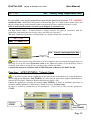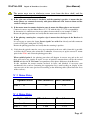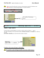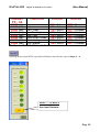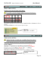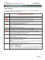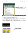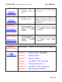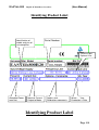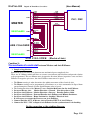
1
EASYfds 800
(User Manual)
Digital AC Brushless Servodrive
User Manual
EASYfds 800
Digital AC Brushless Servodrive
3.3 to 247kW @480Vac
(June -2007 Edition)
Edition
February 2006
Note
Edition 1
Page 1
EASYfds 800
Digital AC Brushless Servodrive
(User Manual)
February 2007
Edition 2
June 2007
Edition 3 PRELIMINARY VERSION (English language)
Pay particular attention to things indicated on the manual when this sign
appears.
The producer reserves to apply technical modifications to improve the
apparatuses, without the obligation of preventive information
All rights are reserved.
No part of the document can in whatever form be reproduced (photocopy, prints, microfilm or other
process) or diffused by using electronic systems, without the written approval of the society:
Page 2
EASYfds 800
Digital AC Brushless Servodrive
(User Manual)
EASYfds 800
( HIGH DYNAMIC DIGITAL SERVOAMPLIFIER FOR BRUSHLESS MOTOR )
Instruction and User Manual
(Assembly, Installation, Working)
Filename
Edition
February 2007
Designed
Date
22-02-2007
Authorized distributor:
All rights are reserved.
The information in this document can endure variations without that preventive communication is
given.
Society does not assume any responsibility for errors or damages derived by the use or wrong
interpretations of the instructions in this publication.
This document cannot be reproduced, neither entire neither partially, without the written
authorization of society
Page 3
EASYfds 800
(User Manual)
Digital AC Brushless Servodrive
GENERAL CHARACTERISTICS :
EASYfds 800
AC Brushless Servodrive model: Monoaxis.
Voltage Input Power Line: 200Vac Min - 530Vac Max (3 phase Line).
Auxiliary feed services: 24 Vdc - 1.0A ( 3A Max con fed Motor Brake).
Inner EMI Net Filter (TUV emc approved).
Intelligent management and direct pilotage integrated Motor Brake (Max 2A).
•
Dynamic Braking of the Axis’ function in case of error or disable
Power’s stage: Module IGBT: last generation, totally isolated and protected.
PWM with double frequency modulation, from 8 Khz until 16 Khz.
Nominal Current: from 4A until 300A.
Max Current: from 8A until 500A.
Special Function (Custom Firmware), available on demand.
Accurate measure of the Currents Motor Phase with sensors to effect HALL
Measure and Monitoring of tension DC Power Bus opto insulated.
Relief and signaling Error for lack of 1 or more phases Net Line (AC Failure).
Unit of recovery energy integrated braking (Internally Brake Resistor).
Modality of operating in Speed (1° income analogic Vref: +/- 10V).
Modality of operating in Speed (Digital Command from Remote: Digital Link).
Modality of operating in Brace (1° income analogic Vref: +/- 10V).
Modality of operating in Brace (Digital Command from Remote: Digital Link).
Modality of operating in Position: Manual Jog (Digital Input IN1-IN2).
Modality of operating in Position: Pulse e Direction (Remote Digital Link or D.Inputs).
Modality of operating in Position: Point to Point (Remote Digital Link or D.Inputs).
Modality of operating in Position: Follower Axis e Master Axis (Electric Axis).
Modality of operating in Position: External digital Encoder (Line Driver RS422).
Dynamics limitation of the Current (Brace) (2° income analogic Vref: 0/ +10V).
Dynamics limitation of the Speed (2° income analogic Vref: 0/ +10V).
Page 4
EASYfds 800
Digital AC Brushless Servodrive
(User Manual)
Motor Transducer: Resolver (Standard), Facoder (Optional), digital Encoder (Optional).
Max length of Resolver cable= 25m (Standard), 50m (Special cable on demand).
Max length of Motor cable = 25m (Standard), 50m (Special cable + Toroid on demand)
Protections: Full Protection.
Resolution acquisition Resolver = 12-14-16 Bit.
Output Emulous increasing Encoder: 256 Min to 65.536 Max (Pulse/Revolution).
Pilotage of rotating and linear motor.
Programmable Motor Poles: 2, 4, 6, 8, 12, 16, 24(Poles).
N° 8 Digital Inputs Opto insulated (0-24Vdc).
N° 4 Digital Outputs Opto insulated ( 24Vdc 50mA).
N° 1 Digital Output signaling the Working State of Servodrive (Fault).
N° 2 Programmable Analogic Outputs (D/A 12 bit) for each Monitoring User.
N° 1 Analogic income (V.Reference) +/- 10Vdc ( Resolution A/D 16 bit).
N° 1 Analogic Income (Limitation Income) 0 /+10Vdc ( Resolution A/D 12 bit).
N° 1 Digital communication door RS232, (File RS232 to RS485 Optional).
FieldBus: Interface PROFIBUS / CAN Optional integrated.
Digital Link Multidrop integrated for digital interconnession until N°15-23 Servodrives.
Function Null mechanical Resonance: digital compensation mechanical resonance.
Function AutoSet Current Loop Automatic digital compensation current ring
Function Resolver Autophasing, digital compensation Phase’s corner (Manual/ Auto)
Function AutoOffset speed, Automatic digital compensation (Analogic Vreference)
Function Autotuning Speed Loop: digital and completely automatic proceed for
determining and setting up of Gain and Optimal parameter Loop Speed.
Visualization State of Parameters and Functioning State: Display 5 numbers.
Programming and Setting up in Buttons on the Façade of the Servodrive.
Programming and setting up from Browser PC ( RS232).
Monitoring and Digital Oscilloscope from Browser PC (Digital Link Multidrop).
Possibility to record an event (Digital Oscilloscope) during the intervention of a protection.
Emulation Digital Remote Command Positioner and Digital Inputs ( Browser PC).
Page 5
EASYfds 800
INDEX
Digital AC Brushless Servodrive
(User Manual)
Page
- Summary ……………………………………………………………………………………………………………………………………6
- Safety’s indications.........................................................................……………………………………...........……......…………....10
- Directions and Europeans Laws....................................................……………………………………............…….…...........11
- Agreement CE / TUV emc....................................................…………………………………………………………..….……...11
- Regulation EMC..............………………………………………………………………......................................................….......…...12
- Reference law EN 50082-2 restricted distribution
...........................….……………..........…...........13
-Conforming Usage of Servoamplifiers series EASYfds 800 .......................................……………...………...13
- Carriage, stockage, maintenance................................................................………………………………..................……….....14
- Mechanical Dimensions……………………………………………………………………………………………….……………..16
- Picture servoamplifiers series EASYfds 800 R24...............................……………………..........................…….....17
- Introduction.....................................................................................……………………………………………...................................…...18
- Models list series EASYfds 800.....................................................…........……………………………….............………..…..19
- Technical Characteristics..........................................................................………………………………………..........................….19
- Electrical Characteristics.............................................................................………………………………………...............……….20
- Dynamic Performances………………………..…………………………………………………………………………..…….…....21
- Protections list.................................................................................................…………………………………………..............………..21
- Technical data table.......................................................................................…………………………………………..........………....22
- Environment Conditions and ventilation requested.....................................................…………………………...........23
- Regulations and sections of motor cable and net..............................................................…………………………........24
- Regulations and sections of Resolver cables and control system.............………………………........................25
- Regulation Fusibles Income Net.............................................................................………………………………......……....25
- Installation………………………………………………………………………………………………………..……………………........26
- Connection to the Net…………………………………………………………………………………………...…………………….26
- Connection to the motor………………………………………………………………………………………………..….......…....27
- Kind of Typologies of Connection Motor and Cables’ Length………….………………………….…………....28
- Regulations Connections Net (TT-TN)…………………………………………………………………….….………….….29
- EASYfds 800 Signal Connections…………………………………………………………….…………………………......30
- Typical Wiring Diagram……………………………………………………………….…………….…………………………....31
- Connection Resolver (CN2) and Control (CN3)...........................................................……………………….....….......33
- Connection serial line RS232 + Digital Link Multidrop (CN1)……………….……..……………….…..34
- Indications of working state………….................................................................………………………………..........…….......35
- Display’s state…........……………………………………………………………………………………………………………………36
- Programming or Modifying Parameters on the Frontal panel Keyboard.…………………………...…......38
- Programming or Modifying Parameters on the Browser PC (Serial RS232)…..…………….…….…..39
- Setting up Parameters of calibration….………………………………………………………………………….…...…...40
- Setting up Password…….…………………………………………………………………………………………………………....43
- Setting up N° Pole Motor’s poles.………………………………………………………….…………………...……………....43
- Setting up resolution Resolver (12 / 14 / 16bit)…………………………………….………………...…..……………....44
- Setting up N° impulses /revolution Emulation Encoder (12, 14 bit)………...…………………….………....44
- Setting up IxT Gain………………….…………………………………………………………………………………..………….….45
- Selection mode VReference inner / outer………………………………………………………………………….…...47
- Setting up working mode Speed / Current-Couple………………..…………………………………...……....47
- Selection filter Low-pass type V.Reference…………………...…………………………………………...….……….…..48
- Selection Gain Current Loop…………………………………………….……………………………………….…………….….49
- Selection Integrative Gain Velocity Loop…………………………………………………………………………...……..50
- Setting up proportional Gain Velocity Loop………………….…………………………………………………..……….51
- Function digital oscilloscope: Scope………………..………………………………………………………………….…...52
- Scope Diagrams (optimizing tuning servo loop)………………………………………………………………………..53
- Setting up Max Motor Current …………………………………….……………………………………………….……………54
Page 6
EASYfds 800
Digital AC Brushless Servodrive
(User Manual)
- Setting up Nominal Motor Current………………………………………………………...……………………………...…..54
- Setting up Nominal Value V.Reference (7,0 – 10,0 V)………………………………………...……………….……55
- Setting up Motor Speed..e…………………………………………………………………………………………………….…….56
- Setting up automatic proceed Offset compensation………….….…………………………………...…………...56
- Compensation Offset External V. Reference………………………………………………………………...…….…...57
- Compensation Offset Internal V. Reference……………………………………………………………………….……57
- Setting up Ramp Time…….…………………………………………….………….…………………………………………………58
- Setting up Drive Pre-Alarm Temperatures .…………..…………………………………………………………..…….…58
- Visualization: Transducer Type………………….………………………………………………….…………………….…59
- Visualization ( 8 bit ) V Reference………….……………………….…………………………………………………………59
- Visualization ( 8 bit ) Speed…………………………………………..…..………………………………………………………..60
- Visualization ( 8 bit ) Motor Current (momentary)……..…….………….…………………………………………….60
- Visualization ( 8 bit ) Medium Motor Current (IxT)…………….…….………………………………………..……..60
- Visualization ( 8 bit ) Servoamplifier temperature……………….…………………………………………………..…61
- Visualization ( 8 bit ) Voltage DC Power bus …………….…..……..……………………………………..………….....61
- Visualization ( 8 bit ) External REFLIMIT voltage………….…………………………………………………….…..62
- Visualization software version (Software Relise)…..……………..……..……….…………………...……………62
- Setting up automatic proceed Autophasing Revolver…………………….…………….……………………….63
- Visualization with sign of the computations Emulation Encoder (1 Turn)……………..……………...…67
- Selection Working Mode: Normal / Wave / Positioner………………………...………………………….………...67
- Internal Wave form (acceleration) setting up time T1…………………….…………………………………….69
- Internal Wave form (acceleration) setting up time T2………………….……………………………………….69
- Internal Wave form Speed…………………………………………………………...…………..…………………………….…70
- Internal Wave form Start / Stop…………………………………………………………………………………………………70
-Visualization N° of matricula Servoamplifier……………………………………………..………………….……….70
- Auxiliary Table reading of parameters ( x User test)………………..…….….………………………...……………71
- Recording Auxiliary Table
( x User test)……….……………..………….………………………………………...…71
- Reading Default Parameters
( Factory calibration)…………..……………………………………….……….71
- Operative Table reading of parameters (Normal working )…..………………………………………………..…72
- Recording operative table ( STORE )……………………………………….……………………………………..…....72
- MONITORING (Working State)…………………………………………………..……………………………………..….72
- Functions’ list for the working mode Positioner…………………………………………………………..……….73
- Setting up stop time Positioner in emergency condition…………….……………….………………………73
- Setting up Zero axes Mode selection ……………….……………………………………………………………….…….74
- Manual Control JOG +/- From converter buttons……………………………………………………………...….75
- Setting up Position’s points (Point to Point) and Software End of Stroke………………………...76
- Setting up Position’s points (Step Mode)……………………………………………………..……………………....…77
- Setting up Positioner’s Speed…..……………………………………………………………………………………..…….…..78
- Setting up execution speed Zero axes……..………………………………………………………………………………......79
- Setting up Moving Speed Manual JOG +/-……………………………….………………………..…………………..…..79
- Setting up Positioner acceleration time…………………………………...………………………………….……….….…...80
- Setting up Positioner deceleration time ……………………………………..………………………………..……………...81
- Setting up position’s Gain ring (KE)……………………………....…………...…………………………………………..82
- Setting up Servo Error Positioner……….…………….……………………………….…………………………………….....82
- Visualization of Digital Input State ( Input 1……to Input 5)……….……………………………….…….83
- Visualization of Digital Output State ………………….………………………….…………………………..…….….…85
- Setting up Speed of profile of electronic cams (Speed Rate)……….……………………………………………85
- Setting up and visualization Options operation Modality………………………………………...…………..86
- AutoTuning Speed loop Gain………....…………………………………………………….…………...…………………......87
- Visualization Size Servoamplifier (Size)………………………………………………………………..……………....…88
Page 7
EASYfds 800
Digital AC Brushless Servodrive
(User Manual)
- Setting up Digital Node Address……………………………………………………………………………….………….…88
- Setting up function Motion Direction……………………………………………………………………....…………….…89
- Setting up function Max Positioning Error count………………………………………………….……….………....89
- Setting up Function Brake Motor…………………………………….…………………………………..…………………90
- Setting up function Null Mechanical Resonance………………………………………………...……………………90
- Setting up Programmable Analogic Output Monitoring………………………………………………………..…...91
- Setting up AC Failure (Mono/Three Phase Power Lines)………………………………………..……...…..91
- Setting up Type External Reference LIMIT……………...……………………………...……………………………..…92
- Setting up Jog Mode Speed……………………………………………………………………………………………………..….93
- Setting up Acceleration Time in REMOTE SPEED…………………………………………………...………....93
- Setting up Watch Dog Time-out in REMOTE SPEED…………………………...………………………..…...94
- Setting up Watch Dog Disable in REMOTE SPEED……………………………………………………..…..….94
- Visualization STOP causes for Emergency………………………………………………………………………………...95
- Visualization RESOLVER Phase Compensation………..………………………………………………….…………..95
- Emulation controls Remote Positioner………………………………………….….……………………………………..96
- Function table of position’s points Browser……………………..…………………………..……………………..…..….97
- Visualization of Error State and Warning………………………………………………………………………...………...98
- Positioner Communication’s Protocol ( Remote Positioner )…………………….…..99
- Mode : AUTO…………………………………………………………..………………………………………………….……….…100
- Configuration RS232 and available commands……………………………………………………….…………….....101
- Command from PLC /PC to Positioner………………………………………………………………….………………...101
- Reply from Positioner to PLC/PC……………………………………………………………..….………………………...103
- Available commands………………………………………………………………………………………………………………...105
- Reading data from Positioner…………………………………………………………………….……………………………..106
- Positioner state…………………………………………………………………………………….…………………….…………...107
- Errors and warning table ………...…………..………………………...…………………………………………….…..108
- Sample reading command about Positioner state Node 1 ………...…………………..……………………..…..109
- Sample reading about axis quota Positioner Node 1 .…..……...………..…..…………….…..109
- Sample set quota preset Zero axes node 1……………..…………..……..………….......…...110
- Write data to positioner ………………………….……………………………………..……..110
- Procedure Zero axes…………..……………………………………………………………….111
- Complete Position’s command…..…………………………………………….………………112
- Position’s command LITE……………………………….……………….……………………113
- Command of ABORT Position………………………………………………………………...114
- Command of drilling cycle Set (Custom) ……………………….………………………….…115
- Commando of drilling cycle Start (Custom)….……………………...………….…………….117
- Command of Complete Speed Set …………………………………………………………….118
- Command of LITE SpeedSet ……….………………………………………………………...119
- Regulation connection Encoder Emulation RS422 line driver.............................................120
- Indication and Resolution Breakdowns and Anomalies of Working .................................121
- Identifying Product Label ……………….………………...……………………..………….130
- Enclosure: Working mode: Master/Slave/Motion Direction ……………………………...131
- Enclosure: Working mode: AXIS FOLLOWER (Electric axis)………………………..…132
- Electromagnetic Compatibility..................................…………………...……………..........134
Page 8
EASYfds 800
Digital AC Brushless Servodrive
(User Manual)
ATTENTION!!
HIGH VOLTAGE!!
Some inner circuits of the servoamplifier EASYfds 800 are subordinates to
dangerous tensions which could cause serious dangers to the safety of the people
or being really lethal.
It is prohibited to approach whichever part with the fed servoamplifier.
The user must install the servoamplifier in accordance with the actual Norms of Emergency on the
Job, he must follow precisely the indications on this handbook.
Whichever tampering, opening of the servoamplifier or intervention non-authorized involve the
immediate decay of the guarantee.
The declines every responsibility for whichever type of damage deriving from an unsuitable use of
the Converter.
DANGER!!
It is allowed to install and to carry out maintenance operations on the
servoamplifier and on the connected devices exclusively to qualified and trained
staff who has a sufficient electronic knowledge.
It is allowed the putting in service Only to qualified and trained staff with a good
electronic knowledge and a good knowledge relative to the technology of the
servoamplifiers.
Page 9
EASYfds 800
Digital AC Brushless Servodrive
(User Manual)
SAFETY’S INDICATIONS
DANGER!!!
The transport, installation, putting in function and the maintenance
can be entrusted exclusively to qualified and competent technical staff, who has the
necessary requirement in order to carry out the transport, the installation, the assembly,
the putting in function and who knows the working of the servoamplifier and who has of the
opportune qualifications for the development of such activities.
The technical staff must know and observe the following norms and directives:
IEC 364 and CENELEC HD 384 or DIN VDE 0100
IEC- Report 664 or DIN VDE 0110
National accident-prevention dispositions or BGV A2
• It is indispensable to read and to take note of the present documentation before
proceeding to the installation and putting in function of the converter. A wrong use
can involve damages to persons or things. Observe absolutely the technical data and
all the indications on the connection conditions.
•
•
The user has to carry out a careful risk analysis for the machinery and the
switchboard in which the servoamplifier is fixed and enclosed. He must adopt all the
necessary precautions so that unexpected movements of the machinery do not cause
damages to persons or to things.
Not to open the servoamplifier. During the operation all the covers, the doors of the
switchboards and the closets must be closed.
There is the danger of dead, of serious accidents to the persons or to materials.
•
During the operation of the servoamplifier (in hard conditions) high temperatures in
proximity of the dissipater and chassis can be reached. They can catch up advanced
values to 80C°. To manipulate or to operate in proximity of the servoamplifier being
adopted are necessary all the precautions in order to avoid scalds.
After to have stopped the servoamplifier, please attend 5 minutes at least so that
temperature of the parts comes down less than 45 C.
•
It is prohibited to operate on the clips or connectors of the electrical connections
when the servoamplifier is working. There can be voltaic arcs with consequent
possible damages to people or things and to the contacts electrical.
•
Wait at least 5 minutes after to have detached the feeding power before touching the
members under tension (as sample electrical contacts) or to loosen the electrical
connections. The electrolytic condensers placed inside o the servoamplifier maintain
a dangerous tension until to 5 minutes after the disconnecting of the feeding tension.
•
The servoamplifier has inner electronic parts sensitive to the electrostatic discharges
which can be damaged from a wrong manipulation or from the lack of grounding of
the chassis. Avoid the contact with highly insulators materials (films in plastic, manmade fibers etc), before handling the converter, unload to mass the own electrostatic
charge as an sample through a grounding wire part
Page 10
EASYfds 800
Digital AC Brushless Servodrive
(User Manual)
EUROPEAN DIRECTIVES AND NORMS
The servoamplifier for brushless motors series EASYFDS 800 is a component destined to the
exclusive assembly on electrical systems/blots in the industrial field.
In case of assembly on machinery/systems, the consistent use of the servoamplifier is prohibited
until when it comes established that the machine/system satisfies the requirement sets up from the
Directive Blots 98/37/CE and the Directive in matter of Electromagnetic Compatibility
89/336/CEE.
Norms EN61800-3, EN50081-2, EN50082-2 must be observed.
DANGER!!! The producer of the machinery/system has to realize an accurate risk analysis
for the machinery and to adopt the necessary measures so that eventual unexpected movements
do not cause damages to persons or to things.
The Directive on the low tension 73/23/CEE inherent to the servoamplifier demands the respect of
the norms harmonized of series EN 60204-1 and EN50178
The observance of the limit values demanded from the directive in matter of electromagnetic
compatibility of the system machinery or switchboard is under the responsibility of the
producer of the system machinery or switchboard.
This documentation contains the indications for an installation in compliance with the directive in
matter of electromagnetic compatibility, like shielding, corrected grounding, manipulations of
connectors and rests of cables.
Conformity
TUV EMC
The tests of electromagnetic compatibility have been conduct in authorized and certificated TUV
laboratory.
Conformity
CE
The Servoamplifiers series EASYFDS 800 are in accordance with the Directive on the
electromagnetic Compatibility 89/336/CEE and to the Directive on the low tension 73/23/CEE.
Certification Files: File: 04/44A, File: RD2004/017A, File: SIC03188A, File: V03/170A.
List of standardized tests: References Norms
Susceptibility Test to electrostatic discharge
(Norm CEI EN 61000-4-2)
Susceptibility Test to disturb from the net (BURST)
(Norm CEI EN 61000-4-4)
Susceptibility Test to disturbs induced on cables of power/signal/Command
(Norm CEI EN 61000-4-4)
Susceptibility Test to electromagnetic fields irradiates to radiofrequency (26 to1000Mhz ,
AM 80% A 1 Susceptible
(Norm CEI EN 61800-3 Part 3 par. 5.3.3.1)
Susceptibility Test to impulsive disturbs with high energy
(Norm CEI EN 61000-4-5)
Susceptibility Test to magnetic disturbs to net frequency
(Norm CEI EN 61000-4-8)
Susceptibility Test to tension’s variation of Net
(Norm IEC 1000-2-1 / 2- 4)
Susceptibility Test to tensions’ holes
(Norm IEC 1000-2-1)
Susceptibility Test to quick interruptions
(Norm IEC 1000-2-1)
Susceptibility Test to dissymmetry of tension
(Norm IEC 1000-2-2 / 2-3)
Susceptibility Test to variation of net frequency
(Norm IEC 1000-2-2 / 2-4)
Susceptibility Test to net harmonics
(Norm IEC 1000-2-2 / 2-4)
Susceptibility Test to commutation’s holes
(Norm IEC 1000-2-2 / 2-4)
Harmonic Measurement of the feeding current
(Norm IEC 1000-2-2 / 2-4)
Page 11
EASYfds 800
Digital AC Brushless Servodrive
(User Manual)
Measurement of fluctuations flicker induced in the feeding
(Norm CEI EN 61000-3-3)
Susceptibility Test to disturbs lead-induced from fields to radio frequency ( 150Khz to
80Mhz, AM 80% a 1 Khz) on feeding cables
(Norm CEI EN 61000-4-6)
Susceptibility Test disturbs lead-induced from fields to radio frequency ( 150Khz to 80Mhz,
AM 80% a 1 Khz) on Data/command cables
(Norm CEI EN 61000-4-6)
Measurement of commutation’s holes
(Norm IEC 146-1-1)
Test of impulsive tension
(Norm CEI EN 50178 Par 9-4-5-1, Tab.17, column 4)
Reliefs of radio interference
(Norm CEI EN 55011 e EN61800-3)
Tests and verifications of conformity to Norm CEI EN 50178 (Electrical safety)
Verification distances of isolation
(Norm IEC 664-1 , EN 60950-1 , EN 50178)
Verification accessibility to dangerous tensions
(EN 60529)
Protection against electric shock and danger of Energy transfer
(EN 60950-1)
Contact current and current in the protection conductor
(EN 60950-1)
Regulamentation of the grounding protection
(EN 60950-1)
Dielectric Rigidity
(EN 60950-1)
Held to allpied tension
(EN 60146-1-1)
Test of impulsive tension
(EN 50178)
Thermal prescriptions
(EN 60950-1 , EN 60146-1-1)
Dry heat test
(EN 50178)
Damp heat test
(EN 50178)
Circuits SELV
(EN 60742 / EN 61558-1)
General requests for electrical workings
(EN 61136-1)
Machinery for the information’s technology
(EN 60950-1)
Test of susceptibility to sinusoidal vibrations
(Norm CEI EN 50178:1999)
On page 132 are described the indications regarding the installation for the execution of the carried
out measurements, differences regarding the installation described in the documentation impose to
the customer the execution of new measurements in the own equipment/machinery or switchboard in
order to satisfy law requirement.
UL
and
Cul Compliants
The Servoamplifier EASYFDS 800 is planned and constructed in order to satisfy all requirements
demanded from actual Norms UL and cUL. (UL and cUL Compliants).
Prescriptions EMC
The Servoamplifier EASYFDS 800 for brushless motors is a product destined to be incorporated in
more complex equipment; generally it is mounted inside of a closet or switchboard, because the
servoamplifier is connected with other equipment or numerical control. Therefore the
Electromagnetic Compatibility depends on factors that are not under the control of the manufacturer
of the converter, but depends on the application, from the correctness wirings and shielding cables of
the switchboard/machinery and grounding.
The Servoamplifier EASYFDS 800 as single object satisfies requirement for brand CE, however
when it is installed in a box or electrical closet, it is necessary the correct employment of the user in
order to respect of the conformity of the brand CE of the entire equipment.
Page 12
EASYfds 800
Digital AC Brushless Servodrive
(User Manual)
The wrong use inside the switchboard can not to satisfy the overcoming of the tests for the
conformity of the brand CE of the entire equipment, therefore the user will to carry out the
application and the wirings in competent way.
Norm of Reference
EN 50082-2
narrows Distribution (According to Atmosphere or Industrial Atmosphere).
Definitions
Narrow distribution: modality of commercialization in which the constructor limits the supply
of apparatuses to suppliers, customers or users who, separately or jointly, have technical competence
of requirement EMC for the application of servoamplifier with electrical working.
According to Environment or Industrial Environment: Environment which comprises
the users Industrial different from those directly connected to an electrical feeding net with low
tension which feeds buildings used for domestic utilizations.
Conforming use of servoamplifiers.
The servoamplifiers are employed as parts on systems or on electrical machinery and can be put in
function only as members integrated in the system.
The producer of the switchboard or machinery has to realize a careful risk analysis for the
switchboard or machinery and he has to adopt all the necessary measures so that eventual unexpected
movements do not cause damages to persons or to things.
In case of use of the servoamplifier in domestic, commercial and industrial sphere, as also in small
companies, the customer must adopt measures of additional net filtrations.
The Servoamplifiers series EASYFDS 800 can be used with directed connections to industrial
three-phase nets with grounding (net TN, net TT with ground Neutral center and symmetrical
nominal current of max 5000 A to 528Vac-Max).
The servoamplifiers cannot be put in function in industrial three-phase nets without grounding
or in nets with not symmetrical grounding with a tension greater than 305Vac. As regards the
connection to nets different from net TN, net TT with ground Neutral, for emergency reasons it is
indispensable to use a de-coupling transformer, as indicated to page 29.
The servoamplifiers can only work in a switchboard into a closed closet. The maximum
temperature admitted inside of the switchboard or closet during the working is 45 C°; in the
switchboard or closet a systems of aeration or air conditioners can be necessary in order to guarantee
a temperature max of 45C° inside of the closet in conditions of elevated external temperatures.
A protection (thermo-switch) is requested because the operation of the servoamplifier can be
stopped if the temperature inside of the closet exceeds the 45C°; that concurs to guarantee the
operation in the parameters prescribed from the constructors of the electronic parts. Consequently are
requested several periodic controls of cleaning, filters air of closet and operation of ventilation or
arranges of cooling.
Page 13
EASYfds 800
Digital AC Brushless Servodrive
(User Manual)
The Servoamplifiers series EASYFDS 800 are designed exclusively to the enslavement of brushless
servomotors synchronous with regulation of Brace, Speed and Position. The Brushless servomotors
must have nominal tension of isolation during the working bigger than the tension of intermediate
circuit BUS DC given by the servoamplifier.
As for the power wirings (Net and Brushless Motor) use only branch cables of section adapted to the
used servoamplifier size, refer to the table on page 24.
It is necessary to insert fuses or magnetotermic protection as protection of the connection
between the net three-phase and the 400/500 income Vac lines R-S-T servoamplifier clips. As
regards the safety, it is indispensable the use of the fuses indicates on the table on page 25, refer
the size of the used servoamplifier.
Transport, stockage, maintenance.
Transport: Only skilled staff, only in original packing of the producer. Avoid
impacts, the temperature must be comprised between: -25C°/+70C°, the atmospheric
humidity cannot exceed the relative humidity max 95% in absence of condense.
Stockage: only in original packing of the producer, temperature - 25C°/+ 55C°,
relative humidity max 95% in absence of condense. The support or shelving must
refer to a conductive support put to earth in order to avoid electrostatic discharges.
Duration in warehouse: 1 year without any limitations, if greater of 1 year it is
necessary to execute regeneration operation of condensers which must be carried out
feeding with monophase tension 230Vac for approximately 60 minutes between the
clips income net R-S.
Maintenance: the Servoamplifiers series EASYFDS 800 do not need of
maintenance, inside there are not fuses, it is prohibited to open the apparatuses, the
eventual inobservance involves the cancellation of the guarantee.
Page 14
EASYfds 800
Digital AC Brushless Servodrive
(User Manual)
DANGER!!!
This handbook is for technical staff with the following requirement:
•
TRANSPORT: Only staff with knowledge in matter of moving of electronic equipment
sensitive to the electrostatic discharges.
•
INSTALLATION: Only technicians with attestation of electro technical formation.
PUT IN FUNCTION: Only technicians with wide knowledge in the fields of electro
technical/electronic and techniques of electrical working.
Picture
EASYfds 800 R24
Page 15
EASYfds 800
(User Manual)
Digital AC Brushless Servodrive
F
A
A
H
MODEL
A
B
C
D
F
G
H
EASYfds 800 R05
19
76 273
300
/
9
18
EASYfds 800 R10
19
76 273
300
/
9
18
EASYfds 800 R12
19
76 273
300
/
9
18
EASYfds 800 R16
19
76 273
300
/
9
18
EASYfds 800 R20
19
93 273
300
/
9
18
EASYfds 800 R24
19
93 273
300
/
9
18
EASYfds 800 R32
19 154
273
300
33
9
18
EASYfds 800 R40
19 154
273
300
33
9
18
EASYfds 800 R50
19 154
273
300
33
9
18
EASYfds 800 R80
19 154
273
300
33
9
18
EASYfds 800 R100
19 154
273
300
33
9
18
EASYfds 800 R300
19 255
495
525
33
9
18
H
LINE
LINE
MOTOR
MOTOR
EASYfds 800
EASYfds 800
DISPLAY
DISPLAY
SEL
-
+
C
D
SEL
-
RES
R32
TO
R05
R100
G
D
TO
R20
CNC
RS232
RS232
MECHANICAL
DIMENSIONS
C
RES
CNC
I/O
+
I/O
24Vaux
24Vaux
G
B
B
Page 16
EASYfds 800
Digital AC Brushless Servodrive
(User Manual)
PICTURE EASYfds 800
Size: R24, R16A, R08 (24, 16, 08 Ampere Nominal Current)
Page 17
EASYfds 800
Digital AC Brushless Servodrive
Picture
EASYfds 800 R24
Picture
EASYfds 800 R16
(User Manual)
Picture
EASYfds 800 R08
INTRODUCTION
The servoamplifier series EASYFDS 800 is a converter with three-phasic stage of power with
IGBT modulated in PWM adapted to the pilotage of Rotating Brushless Motors equipped with
Resolver transducer, Facoder. Linear Brushless Motors equipped with digital Encoder + Hall
sensor. Completely galvanically protected and isolated, it uses the most well-developed parts to
the ends to obtain the best results and trust.
Net Income: 200 to 530Vac (480Vac 3Phase Nominal). Only nets with symmetrical grounding
net
Feeder internal services: 24Vdc +/-10% 1.0A Nominal.
Adjustments and digital sets up optimized to simplify the putting in function.
Page 18
EASYfds 800
Digital AC Brushless Servodrive
(User Manual)
Programming and set up parameters on keyboard on frontal panel, or with the use of an
appropriate program (Browser) compatible with Windows 95, 98, NT, 2000, XP, connecting the
computer to accessible serial line RS232 on the frontal panel of the servoamplifier series
EASYFDS 800.
Digital Brake: Digital Management and direct pilotge of motor brake.
Dynamic Brake Function: Function of digital brake in case of fault or of brake’s lack.
BUS of Field: ProfiBus / Can Open (Optional)
Digital Link Multidrop:
Sending and Receipt of digital data, for remote function (Communication protocol).
Remote Positioner, Digital Speed Command.
Connexcting Digital Link until N°15 Servoamplifiers expansible until N°23.
Indication of functioning state and/or error indication bi 5 numbers display.
Incorporated EMI Filter to reduce the emixions on the net conformly to CE norms.
Autophasing Resolver:
1) Assisted automatic proceed for manual regulation of the corner of timing of the resolver.
2) Automatic proceed for electronic compensation of the corner of timing of the resolver
Autocompensation Offset circuit income differential External Vreference.
AutoTuning: Automatic proceed with rlief Real Time of the dynamic charachteristics of axis and
consequqntly auto-set up and optimal regulation of the gain’s parameters.
Inner Positioner:
Mode Point to Point = N° 15 positions programmable for autolearning or Set.
Modo Step
= N° 7 positions programmable for autolearning or Set.
Modo Remote
= (Communication protocol) from PC, PLC o CNC. Digital LinK.
Input / Output:
N° 5 Digital Output.
N° 8 Digital Input.
N° 1 Digital Input
( N° 4 programmable + N° 1 digital Output: Fault )
( N° 8 programmable used for Positioner and special function).
( Income Enable Servoamplfier).
LIST OF SERVOAMPLIFIERS’ MODELS EASYFDS 800 :
Page 19
EASYfds 800
(User Manual)
Digital AC Brushless Servodrive
Power supply
Nominal
Current
Max
Current
EASYfds 800 R05
200 to 530Vac 3Phase
5 Arms
10 Arms
250 x 76 x 241
(mm)
EASYfds 800 R10
200 to 530Vac 3Phase
10 Arms
20 Arms
250 x 76 x 241
(mm)
EASYfds 800 R12
200 to 530Vac 3Phase
12 A rms
24 A rms
250 x 76 x 241
(mm)
EASYfds 800 R16
200 to 530Vac 3Phase
16 A rms
32 A rms
250 x 76 x 241
(mm)
EASYfds 800 R20
200 to 530Vac 3Phase
20 A rms
40 A rms
250 x 93 x 241
(mm)
EASYfds 800 R24
200 to 530Vac 3Phase
24 A rms
48 A rms
250 x 93 x 241
(mm)
EASYfds 800 R32
200 to 530Vac 3Phase
32 A rms
64 A rms
250 x 154 x 241 (mm)
EASYfds 800 R40
200 to 530Vac 3Phase
40 A rms
80 A rms
250 x 154 x 241 (mm)
EASYfds 800 R50
200 to 530Vac 3Phase
50 A rms
100 A rms
250 x 154 x 241 (mm)
EASYfds 800 R80
200 to 530Vac 3Phase
80 A rms
120 A rms
250 x 154 x 241 (mm)
EASYfds 800 R100
200 to 530Vac 3Phase
100 A rms
160 A rms
250 x 154 x 241 (mm)
EASYfds 800 R300
200 to 530Vac 3Phase
300 A rms
500 A rms
525 x 255 x 327 (mm)
Model
Mechanical
Dimensions
TECHNICAL CHARACTERISTICS:
POWER SUPPLY
Power Supply voltage
Vac
200 Vac to 530 Vac (3 Phase Line)
Net’s Nominal Tension
With symmetrical grounding ( TN- TT )
Frequency line
Hz
45 to 60 Hz
Vdc
800 Vdc
Net’s Frequency
Max Vbus clamping
(max tension from Bus DC during the braking)
Inner Tension DC max
Nominal input current A
4A to 300A
(It’s depends on the size of the convertor used)
Current Absorbed from Net
ELECTRICAL CHARACTERISTICS:
Temperatures
Range of working’s temperature
C°
0 to 45 C°
(It can be necessary the ventilation: It’s depends
Page 20
EASYfds 800
Digital AC Brushless Servodrive
Vac
on the size of the convertor used)
4A to 300 A
(It’s depends on the size of the convertor used)
8A to 500 A
(It’s depends on the size of the convertor used)
2.5 mH (Phase-motor/Phase). If lower, insert a
three-phase inductor to obtain 2.5mH min.
16 to 8 Khz
Modulation PWM to optimize zero crossing and
to obtain high performance of current’s loop)
0.96 Vac input line max
Vdc
900 Vdc max. ( Vdc Bus)
Vdc
150 Vdc min. ( Vdc Bus)
Continuous current
A
Maximum current
from 0.4 sec to 10 sec max
Motor Inductance (Minimum
value requested)
PWM frequency
A
V Power out max
Max Vout towards the motor
Overvoltage
Overvoltage’s protection
Undervoltage
Undervoltage’s protection
Auxiliary power
Rendering of power’s circuit
mH
kHz
W
%
Temperature Protection Max
Temperature heat sink
C°
Resolver Frequency
Frequency etc. resolver
Resolver Resolution
Resolution (bit) resolver
N° Motor Poles
Programmable Motor’s Poles
Encoder Emulation
N° programmable emulated
computations
Fault output
Signal fault convertor (out
Optois.)
kHz
V.Reference input
Analogic Income (differential)
Enable input
Digital Input opto insulated
Input 1.....Input 8
N°8 Digit Input. Opto insulated
Output 1.....Output 4
N°4 Digital Output opto
insulated
(User Manual)
22 VA (24Vdc +/-10%) Absorbed power services
95 to 98%
(It’s depends on the size of the convertor used)
80 C°
(Threshold of intervention of thermic
protection)
12.5 kHz (sinusoidal excitation)
Resolution Resolution: 12/ 14/ 16 bit
2 / 4 / 6 / 8 / 12/ 16 / 24 Motor Poles
N° Poles of Brushless Motor
Pulse/Turn 128,256,512,1024
= 12 Bit resolution
512,1024,2048,4096
= 14 Bit resolution
2048, 4096, 8192, 16384 = 16 Bit resolution
mA / Vdc Opto insulater out =
50 mA 24Vdc
(Close x drive OK)
Danger: Pay attention to polarity of opto
insulatedre !!
V /Kohm + / - 10 V Nominal References
Input Range : +/- 7V to +/- 10V
10 Kohm Income’s impedance
mA / Vdc Digital Input (Income High 1 = permission)
Input current 20 mA
12 to 24 Vdc Input
mA / Vdc Digital Input (Income High 1 = permission)
Input current 20 mA
12 to 24 Vdc Input
mA / Vdc Digital Output =
50 mA 24Vdc
(Closed x Output =1)
Danger: Pay attention to polarity of opto
insulater!
Page 21
EASYfds 800
Digital AC Brushless Servodrive
(User Manual)
DYNAMIC PERFORMANCES
Velocity loop bandwith Hz
Current loop bandwith Hz
V.refer. input bandwith Hz
%
Linearity
Rpm
Max speed setting
Max Speed Tracking rate
Resolver
300 Hz
3000 Hz
Settable on 2 levers:
- 300 Hz Velocity mode
- 3000 Hz Current mode
Better 0.3%
Resolution 12 bit ……= 14.400 rpm
Resolution 14 bit…….= 3.600 rpm
Resolution 16 bit…….= 960 rpm
PROTECTION
Overvoltage DC Bus
Undervoltage DC Bus
AC Failure
Overspeed
Termichal Convertor
Termichal Motor
Short circuit between phase/motor phase and towards ground
Overcurrent Motor
Overcurrent braking resistance
Ixt
Erred connections Resolver
Erred connections Facoder
Erred connections Digital Encoder
Error Servopositioner
End stroke Software (Forward and Reverse Positioner)
Page 22
EASYfds 800
(User Manual)
Digital AC Brushless Servodrive
TECHNICAL TABLE OF SERIES:
EASYFDS 800
Type R04 R08 R12 R16 R20 R24 R32 R40 R50 R80 R100 R300
NOMINAL VALUE
Nominal Tension
Income Net 3Phase model TT/TN
(200Vac Min to 530Vac Max )
Nominal Power (@ 480Vac In )
Function in modality S1
Vac
480 480 480 480 480 480 480 480 480 480
kW
3.3
6.6
Nominal Current.
(Tolerance+/- 2%)
Max Current
(Tolerance +/- 2%)
0,4 sec Min, @ Speed < 250Rpm
10 sec Max @ Speed > 250Rpm
Frequency PWM Power stage.
A
(rms)
A
(rms)
4
Dissipated Power from convertor
with nominal current, included the
nominal current dissipated from
services. Excluded the dissipated
power from R Brake.
Dissipated Power from braking
resistance R Brake.
Cycle
duty
3%.
Attrition
diregardable.
Absorbed Power from services
circuits.
480
480
9.9 13.2 16.5 19.8 26.4 33.0 41.2 66.0 82.4
247
8
12
16
20
24
32
40
50
80
100
300
8
16
24
32
40
48
64
80
100 120
160
500
Khz
16
16
8
8
8
8
8
8
8
8
W
44
70
115 145 175 220 340 410 480 720
960
2650
W
48
77
172 210 320 380 515 640 805 1.28 1.61
KW KW
4.83
KW
W
22
22
22
22
22
22
22
22
8
22
8
22
22
22
1.01
1.01
900
900
Vdc 24.0 24.0 24.0 24.0 24.0 24.0 24.0 24.0 24.0 24.0 24.0
1.0 1.0 1.0 1.0 1.0 1.0 1.0 1.0 1.0 1.0 1.0
A
3.0 3.0 3.0 3.0 3.0 3.0 3.0 3.0 3.0 3.0 3.0
A
24.0
1.0
3.0
Form Coefficient of exit current(I
1.01 1.01 1.01 1.01 1.01 1.01 1.01 1.01 1.01 1.01
_
Nominal and
L loading motor min = 3mH)
Threshold
of
Overvoltage Vdc 900 900 900 900 900 900 900 900 900 900
intervention
DC Bus (overcharge R BRAKE)
Auxiliary Tension (VAUX)
24Vdc+/-10% (No Motor Brake)
Presence Motor Brake @ 2° max
Width of band of
governor ( Current loop )
current Khz
3.0
3.0
3.0
3.0
3.0
3.0
3.0
3.0
3.0
3.0
3.0
3.0
Digital Exit (opto insulated)
Vdc
mA
24
50
24
50
24
50
24
50
24
50
24
50
24
50
24
50
24
50
24
50
24
50
24
50
Digital Income (opto insulated)
Vdc
mA
24
5
24
5
24
5
24
5
24
5
24
5
24
5
24
5
24
5
24
5
24
50
24
5
Page 23
EASYfds 800
Digital AC Brushless Servodrive
(User Manual)
AMBIENTAL CONDITIONS AND REQUESTED VENTILATION:
Temperatures, dampness and stockage
during
Temperature and transport’s dampness
Tensions Tolerance and Net Frequency.
The 3phase Net must be grounding
referred.
Ambiental Working Temperature
Only in original package of producer, temperature –
25C° / + 55C°, relative dampness max 95% without
condense.
Duration in warehouse: 1 year without any
limitations, see page 11 for longer duration
Temperature between -25C° / +70C°, relative
dampness max 95% in absence of condense.
Tension 200 Vac Min - 530 Vac Max
Net frequency:
45Hz min, 60 Hz max
From 0 To +45 C°. With Forced ventilation
For Temperatures higher than +45C°, decrees the
Imax current of -3% for each exceeding C°.
Sample EASYfds 800 R20
Temperature max = +55C°
Setting I MAX = 28A max
55C°- 45C° = 10C° ( 1C° x 10 = 10C°)
3% decreasing x 10 = 30% decreasing Imax
I max = 40A - 30% = 28A max
Working atmospherically dampness
Relative dampness max 95% without condenses.
Installation height
Until 1000m on sea level without any
limitations
From 1000m on sea level until 2500m on sea level it
is necessary to decrease the Imax current of -1.5%
each 100m.
Sample EASYfds 800 R20 installed at 1900m on sea
level.
Setting I MAX = 34.6A max
1900m –1000m = 900m ( 100m x 9 = 900m)
1.5% decreasing x 9 (100m) = 13.5% decreasing
Imax
I max = 40A - 13.5% = 34.6A max
Protection level
IP 20
Soiling level
Soiling level 2 as EN60204-EN50178
Ventilation
Assure the forced air recirculation on the
switchboard in order to guarantee max + 45C° of
inner temperature into the closet.
In particular environmental conditions it can be
necessary to install an air conditioner.
Page 24
EASYfds 800
(User Manual)
Digital AC Brushless Servodrive
REGULATION OF MOTOR CABLES AND NET INCOME
Connection’s model
Cables’ section
Cables’ characteristics
EASYfds 800 R04
= 1.5mmq
EASYfds 800 R08
= 1.5mmq
EASYfds 800 R12
= 2.5mmq
EASYfds 800 R16
= 2.5mmq
EASYfds 800 R20/ R24 =4mmq
EASYfds 800 R32
= 4mmq
EASYfds 800 R40
= 6mmq
EASYfds 800 R50
= 6mmq
EASYfds 800 R80
= 10mmq
EASYfds 800 R100 = 10mmq
EASYfds 800 R300
Use N° 5 cables
x 6mmq
Max length motor cables max 20m EASYfds 800 R04
= 1.5mmq
Max length motor cables max 20m EASYfds 800 R08
= 1.5mmq
Max length motor cables max 20m EASYfds 800 R12
= 2.5mmq
Max length motor cables max 20m EASYfds 800 R16
= 2.5mmq
Max length motor cables max 20m EASYfds 800 R20/ R24 =4mmq
Max length motor cables max 20m EASYfds 800 R32
= 4mmq
Max length motor cables max 20m EASYfds 800 R40
= 6mmq
Max length motor cables max 20m EASYfds 800 R50
= 6mmq
Max length motor cables max 20m EASYfds 800 R80
= 10mmq
Max length motor cables max 20m EASYfds 800 R100 = 10mmq
Max length motor cables max 20m EASYfds 800 R300
Use N° 5 cables
x 6mmq
Motor cables from 20 to 100 m max. EASYfds 800 R04 = 1.5mmq
Connection Three-phase Net
Connection Three-phase Net
Connection Three-phase Net
Connection Three-phase Net
Connection Three-phase Net
Connection Three-phase Net
Connection Three-phase Net
Connection Three-phase Net
Connection Three-phase Net
Connection Three-phase Net
Connection Three-phase Net
Insert L3phase 0.5mH 08Apk
Motor cables from 20 to 100 m max.
Insert L3phase 0.5mH 16Apk
Motor cables from 20 to 100 m max.
Insert L3phase 0.5mH 24Apk
Motor cables from 20 to 100 m max.
Insert L3phase 0.5mH 32Apk
Motor cables from 20 to 100 m max.
Insert L3phase 0.5mH 40Apk
Motor cables from 20 to 100 m max.
Insert L3phase 0.5mH 64Apk
Motor cables from 20 to 100 m max.
Insert L 3phase 0.5mH 80Apk
Motor cables from 20 to 100 m max.
Insert L3phase 0.5mH 100Apk
Motor cables from 20 to 100 m max.
Insert L3phase 0.5mH 120Apk
Motor cables from 20 to 100 m max.
Insert L3phase 0.5mH 120Apk
Motor cables from 20 to 100 m max.
Insert L3phase 0.5mH 500Apk
600Vrms, 105 C° at strands
600Vrms, 105 C° at strands
600Vrms, 105 C° at strands
600Vrms, 105 C° at strands
600Vrms, 105 C° at strands
600Vrms, 105 C° at strands
600Vrms, 105 C° at strands
600Vrms, 105 C° at strands
600Vrms, 105 C° at strands
600Vrms, 105 C° at strands
600Vrms, 105 C° at strands
600Vrms 105C° shielded <150pF/m
600Vrms 105C° shielded <150pF/m
600Vrms 105C° shielded <150pF/m
600Vrms 105C° shielded <150pF/m
600Vrms 105C° shielded <150pF/m
600Vrms 105C° shielded <150pF/m
600Vrms 105C° shielded <150pF/m
600Vrms 105C° shielded <150pF/m
600Vrms 105C° shielded <150pF/m
600Vrms 105C° shielded <150pF/m
600Vrms 105C° shielded <150pF/m
600Vrms 105C°shielded <150pF/m
EASYfds 800 R08
= 1.5mmq 600Vrms 105C°shielded <150pF/m
EASYfds 800 R12
= 2.5mmq 600Vrms 105C°shielded <150pF/m
EASYfds 800 R16
= 2.5mmq 600Vrms 105C°shielded <150pF/m
EASYfds 800 R20/ R24 =4mmq 600Vrms 105C°shielded <150pF/m
EASYfds 800 R32
=
4mmq 600Vrms 105C°shielded <150pF/m
EASYfds 800 R40
=
6mmq 600Vrms 105C°shielded <150pF/m
EASYfds 800 R50
=
6mmq 600Vrms 105C°shielded <150pF/m
EASYfds 800 R80
= 10mmq 600Vrms 105C°shielded <150pF/m
EASYfds 800 R100
= 10mmq 600Vrms 105C°shielded <150pF/m
EASYfds 800 R300
Use N° 5 cavi
x 6mmq
600Vrms 105C°shielded <150pF/m
The motor cables must have max capacity of 150pF/m and working temperature of 105C°
Page 25
EASYfds 800
Digital AC Brushless Servodrive
(User Manual)
SECTION OF RESOLVER CABLES AND COMMAND CABLES
Connection Resolver and Termichal
protection motor (safety )
Connection encoder emulation output
RS422 LINE DRIVER 26LS31
Differential transmission on salace line.
It is requested ending’s impedance.
Impedance range: 150 ohm min, 470 ohm max.
Command’s signals V Reference
Analogic differential Income +/- 10V.
Impedance 10 Kohm.
Digital incomes
Digital Output
Command signals
4 x 2 x 0.25mmq twisted and single shielded
coppiole + whole screen
Max Length 20 m.
If length > 20m contact the producer. Connect
the screen directly to shell of bulb connector
CN2 and motor side.
twisted and sigle shielded coppiole + whole
screen
Max Length 20 m.
If length > 20m contact the producer.
Connect the screen directly to shell of bulb
connector CN3 and CNC side.
1 x 2 x 0.25mmq single shielded.
Max length 10 m.
If length > 10m contact the producer. Connect
the screen directly to shell of bulb connector
CN3 and CNC side.
0.5mmq
0.5mmq
0.5mmq
Prescription Fuses of Protection Income Net.
It is requested the protection for the connection between the net three-phase 400/500Vac and
clips income net of the servoamplifier, the protection must be single for every servoamplifier.
Use exclusively the prescribed model of Fuse or with the same characteristics.
The use of inadequate fuses during the employment can cause dangerous conditions of in case of
short circuit with possible damages to persons or to things.
The prescribed Fuses are produced from the Bussmann and are accredited: CE, UL, CSA.
Model
EASYfds 800
EASYfds 800
EASYfds 800
EASYfds 800
EASYfds 800
EASYfds 800
EASYfds 800
EASYfds 800
EASYfds 800
EASYfds 800
EASYfds 800
EASYFD 600
Fuse
R04
R08
R12
R16
R20
R24
R32
R40
R50
R80
R100
R300
(Bussmann) series “CUBEFuse”
(Bussmann) series “CUBEFuse”
(Bussmann) series “CUBEFuse”
(Bussmann) series “CUBEFuse”
(Bussmann) series “CUBEFuse”
(Bussmann) series “CUBEFuse”
(Bussmann) series “CUBEFuse”
(Bussmann) series “CUBEFuse”
(Bussmann) series “CUBEFuse”
(Bussmann) series “CUBEFuse”
(Bussmann) series “CUBEFuse”
(OMEGA) series NH2
Fuse’s Code
TCF5
TCF10
TCF10
TCF15
TCF20
TCF25
TCF30
TCF40
TCF50
TCF80
TCF100
NH2G300
Page 26
EASYfds 800
Digital AC Brushless Servodrive
(User Manual)
INSTALLATION
ATTENTION!!! Follow and respect scrupulously all the following indications supplied in
order to cure the installation of the converter series EASYFDS 800
Fix mechanically the converter on the bottom wall of the switchboard or closet so that it has the
dissipater in vertical position.
Leave a free space of at least 20 cm under and 20 cm over of the drive.
If more converters are settled, use the following criteria:
VENTILATION FOR NATURAL CONVECTION:
Fix the converters so to leave a free space of at least 5cm between the converters.
FORCED VENTILATION:
With the forced ventilation it is possible to place side by side the converters (the minimal space 1cm
between them) obtaining therefore minor crow.
GROUND CONNECTION:
The converters series EASYFDS 800 are constituted from a mechanical of galvanized sheet which
concurs to obtain an optimal grounding, which can be carried out indifferently either on the
appropriate screw of the frontal panel or through the slab of bottom for the mechanical implantation
N.B. It is indispensable to connect the converter to ground.
NET CONNECTION:
ATTENTION!!!
Use the maximum caution and all precautions in carrying out the electrical connections either in
the 400 Net Vac or with the motor connections.
RISK of DEATH!!!
ATTENTION!!! Not touch or make electrical connections with inserted tension or
ignited drive: RISK of DEATH!!!
ATTENTION!!! Wait at least 5 minutes from the moment in which the feeding Power
is removed (the inner abilities must be unloaded) before operating on the connections Motor / Net
/ external Brake Resistance (optional).
Page 27
EASYfds 800
Digital AC Brushless Servodrive
(User Manual)
ATTENTION!!!
Do Not open the converter, dangerous tensions are present inside.
There are not any fuses, but only electronic protections, for this reason it is not necessary and
possible to carry out a simple substitution (fuse) or repair.
In case of checking of opening or tampering of the converter the guarantee will decay.
As regards the electrical connections, it is possible to refer to table WIRING DIAGRAM at page 30.
CONNECTION: 400 / 500 VAC LINE
It’s necessary to insert fuses in series to the line as protection from eventual short circuits,
using the correct series to 500 VAC (use the table at page 21)
Depending on the applications it can be necessary to insert an additional net filter in order to render
the system compatible with the norms EMC. It depends on the cables and on the disposition of
power’s cables and net into the switchboard or into the closet; in the servoamplifiers is requested a
net filter on board which, that in the most part of the cases, is enough if the wirings and groundings
are correct. The local p0wer source inside of the converter requires a circuit which limits the
current to the insertion of the net. It is recommended to wait approximately 5/10 seconds
between the moment in which the drive extinguishes and the next relighting so that the
protection’s circuit in inrush current has the maximum effectiveness.
MOTOR’S CONNECTION:
The connection to the motor must be carried out like indicated in the successive figure.
Use shielded cable to low ability (150pF max) and range temperature 105C°.
3 Thread + Ground + screen.
The screen must be connected either from the motor side or the converter side (on the
appropriate screw of frontal panel). For lengths of the motor cable until to 20m is recommended the
use of a toroid N° 3 coils which includes U, V, W (EPCOS B64290l40X830) placed close to the
terminal board of the servoamplifier, In this way the parasitic currents decreases and the motor
bearings’ life became longer. It is important also the connection of the ground thread motor which
must be connected on the clip of the motor to be connected also on the drive (on the appropriate
screw frontal panel)
IMPORTANT!
The ground thread motor must be connected directly on the converter in order to go to ground
through the chassis of the same one, in this a way is avoided to make sliding parasitic high
frequency currents on reported to mass cables.
IMPORTANT!
For cables longer than 20m it is necessary to interpose a three-phase inductance 0.5mH
between the servoamplifier and the motor, so to decouple the parasitic capacities of the motor
cable towards the converter. Place the inductance close to the servoamplifier
CONNECTION: RESISTANCE EXTERNAL BRAKE (Optional)
If used external R Brake. For connection, use shielded thread of length max = 1,5 m. The wiring and
implantation of the resistance Brake will have to be carried out respecting the safety norms for
tensions = 500Vac. The Standard version previews R BRAKE into the drive.
Page 28
EASYfds 800
Digital AC Brushless Servodrive
(User Manual)
Page 29
EASYfds 800
(User Manual)
Digital AC Brushless Servodrive
REGULAION CONNECTION NETS ( TT – TN )
Kind of Net connections ( 400/ 500 Vac )
A) LINE:
400/500 VAC
B) LINE:
Symmetrical grounding
400/500 VAC
WITHOUT
STANDARD CONDITION
GROUNDING
R
PE
L1
S
ISOLATION TRANSFORMER
REQUIRED
LINE: 400/500 VAC
E)
GROUNDING
PE
L2
LINE: 400/500 VAC
F)
L3
Grounding not Symmetrical 2
S
L2
PE
A) Standard Condition.
R
EASYfds 800
L1
S
L3
PE
EASYfds 800
L1
L2
S
T
T
ISOLATION TRANSFORMER
REQUIRED
PE
LINE: 400/500 VAC
R
T
ISOLATION TRANSFORMER
REQUIRED
T
ISOLATION TRANSFORMER
REQUIRED
Grounding not Symmetrical 1
EASYfds 800
L1
S
L3 L2
T
R
L3
EASYfds 800
L1
L3 L2
T
R
ISOLATION TRANSFORMER
REQUIRED
PE
Income line net with symmetrical grounding.
B) Income Line Net without grounding:
It is requested an isolating transformer.
C) Income Line Net with asymmetrical grounding:
It is requested an isolating transformer.
D) Income Line Net without grounding:
It is requested an isolating transformer.
E) Income Line Net with asymmetrical grounding 1:
It is requested an isolating transformer.
F) Income Line Net with asymmetrical grounding 2:
It is requested an isolating transformer.
Page 30
Types of Power Lines connections
S
WITHOUT
Grounding not Symmetrical
EASYfds 800
EASYfds 800
D)
LINE: 400/500 VAC
R
L1
L3 L2
C)
EASYfds 800
(User Manual)
Digital AC Brushless Servodrive
EASYfds 800 SIGNAL CONNECTIONS
CN3
INPUT 8
GND
0- ENCODER OUT
0+ ENCODER OUT
B- ENCODER OUT
B+ ENCODER OUT
A- ENCODER OUT
A+ ENCODER OUT
9
18
8
17
7
16
6
15
5
14
4
13
3
12
2
11
1
10
26
25
24
23
22
21
20
19
-15 VOUT
A+ ENCODER INPUT
+15 VOUT
A- ENCODER INPUT
FAULT2 (OUT EMITTER)
B+ ENCODER-INPUT
FAULT1 (IN COLLECTOR)
B- ENCODER-INPUT
ENABLE INPUT
REFLIMIT
GND 24V
OUT MONITORING 2 (PROGR.)
GND
OUT MONITORING 1 (SPEED)
-VREFERENCE
GND
+VREFERENCE
OUT-MASTER
CNDB26HDFEMALE
CN2
A+ ENCODER INPUT
A- ENCODER INPUT
B+ ENCODER INPUT
B- ENCODER INPUT
GND-ENCODER (OPTIONAL)
+5V-ENCODER (OPTIONAL)
MOTOR THERMAL
MOTOR THERMAL
REF- RESOLVER (R3)
15
10
14
9
13
8
12
7
11
6
5
COSINE+ (S2)
4
COSINE- (S4)
3
SINE+ (S1)
2
SINE- (S3)
1
REF+ RESOLVER (R1)
CNDB15HDFEMALE
CN1
6
1
7
2
8
3
9
4
10
5
11
DIGITAL LINK TERMINATION
12
DIGITAL LINK+ (IN)
13
DIGITAL LINK+ (OUT)
14
DIGITAL LINK- (IN)
15
DIGITAL LINK- (OUT)
RS232-RX
RS232-TX
+5VOUT (Optional)
GND232
GND
CNDB15HDMALE
CN5
Drive ready
0UTPUT 1
0UTPUT 2
0UTPUT 3
0UTPUT 4
+24V COMMON OUT
+15V OUT
GND
GND 24V COMMON INPUT
1
3
5
7
9
11
13
15
2
4
6
8
10
12
14
16
INPUT 1
INPUT 2
INPUT 3
INPUT 4
INPUT 5
INPUT 6
INPUT 7
INPUT 8
S2L 3.5/16
CN4
1
2
3
4
+24V AUX
GND AUX
+BRAKE OUT
-BRAKE OUT
SL 3.5/4
Page 31
Digital AC Brushless Servodrive
(User Manual)
Drive ready
EASYfds 800
Page 32
EASYfds 800
(User Manual)
Digital AC Brushless Servodrive
Connections:
Brushless Motor
Connections:
Line Net 200/530Vac
3 Phase
Connections CN3:
CNC or PLC
(CNDB-HD 26FEMALE)
EASYfds 800
FUSE
LINE
LINE
6
LINE INPUT
REFERENCE
PE
EARTH
SHELL
6
FAULT+ (COLLECTOR)
7
FAULT- (EMITTER)
2
-VREFERENCE
1
-VREFERENCE
8
11
9
+15V OUT
GND
-15V OUT
14
REFLIMIT
5
ENABLE
3
GND
GNDENABLE
INPUT8
19
UA+
4
FAULT OUT
3
FUSE
400/500Vac +10/-20%
LINE
7
INPUT
6
+
LINE
R
S
T
-
FUSE
CN3
1
LINE FUSE REQUIRED
5
SHIELDED CABLE
V.REFERENCE
(+/-10VMAX)
SCREW M4
SHIELD
R3
R1
S3
S1
S4
S2
Input Follower Axis
11
7
6
1
2
3
4
5
THERMAL
THERMAL
REFREF+
SINSIN+
COSCOS+
15
10
14
9
UA+
UAUB+
UB-
6
RESOLVER INPUT
3
20
ENCODER
OUTPUT
UA-
21
UB+
22
UB-
150 OHM RESISTOR
LINE DRIVER
23
U0+
TERMINATION REQUIRED
RS422 (26LS31)
24
U0-
25
GND
SHELL
UA+
UAUB+
UB-
ENCODER
INPUT
ENCODER
INPUT
ENCODER OUT
UA+
UA+
UA-
UA-
UB+
UB+
ENCODER
INPUT
UB-
Input Follower Axis
UB-
SHELL
SHELL
CN1
6
7
10
CN5
RS232
11
9
1
3
5
7
2
4
6
8
10
12
14
16
15
13
+15V OUT (50mA Max)
COMMOUT (+24V)
OUT 1
OUT 2
OUT 3
OUT 4
Drive ready
INPUT 1
INPUT 2
INPUT 3
INPUT 4
INPUT 5
INPUT 6
INPUT 7
INPUT 8
COMMON INPUT (GND24V)
GND
INPUT 24V aux
1
2
+24V ( 1A to 3A)
GND 24V
OUTPUT BRAKE (2A Max)
3
4
BRAKE OUT +
BRAKE OUT -
RX
TX
GND
Digital Link Output
DLINK + (PIN12)
12
DLINK +
DLINK -
DLINK - (PIN14)
14
DLINK + (PIN13)
13
DLINK - (PIN15)
15
Digital
Link
4
1
INPUT
1....8
3
Resistance of Ending
4
11
6
3
OUTPUT
1....4
** To connect pins 11 and 12 on last the drive of the chain
Digital Link Input
6
RX232 (PIN6)
TX232 (PIN7)
GND232 (PIN10)
1
SHIELD CABLE
TO PC
RS232
ConnectionsCN5:
N°8 Input, N°4 Out
Connections:
Digital Link
Connections :
24Vaux and Brake
Out
Page 33
TYPICAL WIRING DIAGRAM
ENCODER INPUT
GND 24 V
PAIR TWISTED AND SHIELDED CABLE
SHELL
SHIELD
+24 V
INPUT8
Enable Asse Elettrico
CN2
THERM
THERM
R3
R1
S3
S1
S4
S2
26
4
MOTOR OUTPUT
TWISTED AND SHIELDED CABLE
4
ENABLE
MOTOR
SHIELDED CABLE
RESOLVER
ENABLE
INPUT
MOTOR
1
V
W
MOTOR
6
U
V
W
3
MOTOR
U
4
BRUSHLESS
1
GROUND
EASYfds 800
(User Manual)
Digital AC Brushless Servodrive
CONNECTION: RESOLVER ( CN2 )
CN2
Connector 15 ways high density bulb (Flying male)
Use cable with twisted and single shielded coppiole + whole screen (Lmax = 20m)
CN2
Pin
Pin
Pin
Pin
Pin
Pin
Pin
Pin
Pin
Pin
Pin
Pin
Pin
Pin
Pin
1
2
3
4
5
6
7
8
9
10
11
12
13
14
15
Connection’s denomination
REF+
SIN SIN+
COS COS+
REFTERMICA 1
GND Supply
ENCODER Input
ENCODER Input
TERMICA 2
+5V Supply
N.C.
ENCODER Input
ENCODER Input
(R1)
(S3)
(S1)
(S4)
(S2)
(R3)
(External Encoder)
(B -)
(A -)
(External Encoder)
(B +)
(A +)
Connection
RESOLVER
RESOLVER
RESOLVER
RESOLVER
RESOLVER
RESOLVER
TERMICAL MOTOR
GND Supply
(External Encoder Follower)
ENCODER (External) (Line driver required: 26LS31 or similar)
ENCODER (External) (Line driver required: 26LS31 or similar)
TERMICAL MOTOR
+5V Supply
(External Encoder Follower)
N.C.
ENCODER (External) (Line driver required: 26LS31 or similar)
ENCODER (External) (Line driver required: 26LS31 or similar)
CONNECITON: CHECK ( CN3 )
CN3
Connector 26 ways high density bulb (Flying male)
Use cable with twisted and single shielded coppiole + whole screen (Lmax = 10 / 20m)
CN3
Pin
Pin
Pin
Pin
Pin
Pin
Pin
Pin
Pin
Pin
Pin
Pin
Pin
Pin
Pin
Pin
Pin
Pin
Pin
Pin
Pin
Pin
Pin
Pin
Pin
Pin
1
2
3
4
5
6
7
8
9
10
11
12
13
14
15
16
17
18
19
20
21
22
23
24
25
26
Connection’s denomination
REFERENCE +
REFERENCE GND
GNDENABLE
ENABLE
FAULT1
FAULT2
+15 VOUT
-15 VOUT
OUT-MASTER
GND
OUT MONITORING 2
OUT MONITORING 1
REFLIMIT
ENCODER Input
(B -)
ENCODER Input
(B +)
ENCODER Input
(A -)
ENCODER Input
(A +)
UA
UA\
UB
UB\
U0
U0\
GND
INPUT 8
+/- 10V max (differential 10Kohm impedance)
+/- 10V max (differential 10Kohm impedance)
GND
0V income Enable (It can be connected to gnd)
Input Enable (range +15V / +24V) Enable =1
Output Fault opto insulated (collector). Income: 24V @ 50mA max
Output Fault opto insulated (issuer). Exit:
24V @ 50mA max
Output voltage +15V
+15 @ 50 mA max
Output voltage -15V
- 15 @ 50 mA max
Output Master Servodrive to Slave
GND
Programmable analogic exit (Monitoring)
Analogic exit Motor speed (Monitoring)
Programmable analogic Income Limitation Cuple or speed
External Encoder Follower
( Line driver required: Type 26LS31 or similar)
External Encoder Follower
( Line driver required: Type 26LS31 or similar)
External Encoder Follower
( Line driver required: Type 26LS31 or similar)
External Encoder Follower
( Line driver required: Type 26LS31 or similar)
Out emulation Encoder (line driver RS 422), 150 ohm ending
Out emulation Encoder (line driver RS 422), 150 ohm ending
Out emulation Encoder (line driver RS 422), 150 ohm ending
Out emulation Encoder (line driver RS 422), 150 ohm ending
Out emulation Encoder (line driver RS 422), 150 ohm ending
Out emulation Encoder (line driver RS 422), 150 ohm ending
GND
Digital Input. Permits the synchrone of the function electrical shaft
Page 34
EASYfds 800
(User Manual)
Digital AC Brushless Servodrive
Connection serial line RS232 (Computer or PC, PLC) (CN1)
CN1:
Connector 15 ways high density bulb (Flying female)
Use shielded cable 2 twisted coppiole + whole screen RS232 (Lmax = 5 meters)
Connect the cable’s screen directly to the shell of connector bulb CN1 and PC side.
CN1
Pin
Pin
Pin
Pin
Pin
Pin
Pin
Pin
Pin
Pin
Pin
Pin
Pin
Pin
Pin
1
2
3
4
5
6
7
8
9
10
11
12
13
14
15
Connection’s denomination
RX 232
TX 232
Comment
(reception
RS232)
(transmission RS232)
(Reception
RS232)
(Transmission RS232)
(mass or gnd RS232)
(Mass or Gnd RS232)
GND
GND 232
Connection serial line RS232 + Digital Link Multidrop (CN1)
CN1:
Connector 15 ways high density bulb (Flying female)
Use shielded cable 2 twisted coppiole + whole screen RS232 (Lmax = 5 meters)
For cable length > 5m until 100m > Use card (Optional) RS232toRS485.
CN1
Connection’s denomination
Pin
Pin
Pin
Pin
Pin
Pin
Pin
Pin
Pin
Pin
Pin
1
2
3
4
5
6
7
8
9
10
11
N.C.
N.C.
N.C.
N.C.
N.C.
Pin
Pin
Pin
Pin
12
13
14
15
Digital Link
Digital Link
Digital Link
Digital Link
RX 232
TX 232
Comment
(Reception
RS232)
(Transmission RS232)
(+5V*)
(GND*)
(Optional)
(Optional)
(+5VSupply Output Optional, 100mA max)
(Gnd Supply Output Optional)
GND 232
(Massa o Gnd RS232)
Digital Link ending ***
If used Digital link multidrop connection: Connect
Pin 11 with Pin 12 on the last Servodrive.
Digital Link Multidrop +
Digital Link Multidrop +
Digital Link Multidrop Digital Link Multidrop -
+
+
-
Page 35
EASYfds 800
Digital AC Brushless Servodrive
(User Manual)
INDICATION WORKING STATE (DISPLAY)
INDICATION WORKING STATE
At each ignition the converter EASYFDS 800 visualizes automatically the Function FF- 40 which
corresponds to the Monitoring Function.
In the normal working, when the converter is stopped and there are not errors, on the Display appears
the written disab.
When the drive is starting (Enable =1) the display indicates the written: 01. GO
The Display indicates also the angular position of the rotor (brushless motor) using the last number,
with the ignition of a single segment (the sense of spin of the segment indicates the sense of spin of
the motor).
If the display it flashes during the use of a function different from the one of monitoring (FF- 40), it
means that an error is happening.
In order to visualize the error it is necessary to select function (FF- 40) monitoring, every error
comes recorded and visualized in accordance with the table on page 23.
Selection of Programming Function from Frontal Panel
It is possible to select the function that one agrees to modify or to visualize using the keys: SEL, UP,
DOWN (1 green key + 2 Blue keys) placed on the frontal Panel.
The green key: SEL it is useful to select the function to visualize or to program.
The blue key: UP (+) it is useful to select a function of increasing number.
The blue key: DOWN (-) it is useful to select a function of decreasing number
At each start the converter visualizes automatically the Function (FF- 40), to select another
function, press Green key (SEL), therefore press one of the two Blue keys (UP) or (DOWN),
relating the function that one agrees to visualize or to program; when on the display the wished
function appears, press Green key (SEL newly); on the display the programmable values will
appear.
Using Blue keys (UP) or (DOWN), select the new value to be programmed or to be visualized.
Visualization error state
If there is an error, the display flashes indicating the error code, there can be GREEN key SEL
and then press the BLUE selection keys +/-.
The presence of an error provokes the stop of the converter with the arrest of the operation of the
stage power and the consequent signaling of Fault. Some kinds of error do not provoke the stop of
the stage power and consequently the signal Faul is not generated: IxT, error servo-positioner,
ending run FW and REW.
In the event of presence of one or more errors, these are signaled and recorded the reset.
To reset the errors it is necessary to disable the servoamplifier (Enable =0), then, when the
servoamplifier is enable (Enable = the 1) the error or the errors are reset, in case of persistence of the
anomaly which caused the errors, these will continue to be visualized until the elimination of the
cause.
For the resolution of the errors, refer to the paragraph: “Out of Order Indication and Errors’ and
anomalies’ resolution” at page 121, for the codification and meaning of Errors refer to the table at
page 36.
Page 36
EASYfds 800
Digital AC Brushless Servodrive
(User Manual)
DISPLAY STATE
Display Visualization
The display with 5 numbers - 7 segments present on the frontal panel has the function to indicate the
working state of the converter and offers the possibility to visualize all the programming functions
which can be carried out by the three keys: Sel, Up (+), Down (-).
DISPLAY STATE
disab
Appears the signal disab if the converter is not enabled and if there are not
errors.
01. GO. -
Appears the signal GO. if the converter is enable and if there are not errors.
, on the right will appear a line indicating the rotation sense of the motor.
The first left number indicates: address node (from 1 …..to 16)
EE -- 01
(flashing)
EE -- 02
(flashing)
EE -- 03
(flashing)
EE -- 04
(flashing)
EE -- 05
(flashing)
EE – 06
(flashing)
EE – 07
(flashing)
Error: 01
Over Voltage
Verify the feeding tension 400/ 500Vac it must be within the specified
tolerances.
Error: 02
Thermal Protection
(ServoDrive / Motor)
Verify the convertor temperature, Cabinet ventilation.
Verify the motor temperature, the Termichal motor connection.
Error: 03
IxT Protection
Verify the correct connection motor phases, the motor brake tension.
Verify setting N° motor Poles, attritions or mechanical stumbles.
Error: 04 Resolver Error
Verify the Resolver Connections.
Error: 05
Over Current
Verify eventual short circuits between motor phases and towards ground.
Verify setting Max Current.
Error: 06
Under Voltage
Verify the feeding tension 400/ 500Vac it must be within the specified
tolerances
Verify the fuses protecting the net.
Error: 07 AC Failure
Lacking of one or more steps of feeding tension400/ 500Vac.
Verify the fuses protecting the net.
Page 37
EASYfds 800
EE – 08
(flashing)
EE – 09
(flashing)
EE – 10
(flashing)
EE – 14
(flashing)
EE – 15
(flashing)
EE – 16
(flashing
AA – 21
(flashing)
Digital AC Brushless Servodrive
(User Manual)
Error: 08
OverSpeed
Verify the correct set up of speed parameter (FF 14).
Verify the correct set up of Gain parameters speed loop.
Error: 09
Follower Encoder Error (Wire or Connections Error)
Verify The connections Encoder Input (Follower) and the correct value of
feeding tension external Encoder.
Error preview only if external Encoder is used for elliptical axis.
Error: 10 Digital Encoder Transducer Error
(Wiring Error)
Verify The connections of income Digital Encoder or Facoder, used as motor
transducer and the correct value of feeding tension
Error preview only if the Encoder is used substituting the Resolver
Error: 14 Servo Error Positioner
Verify la Cinematic, attritions or mechanical stumbles. Servo Error set up
with too little value or Gain KE and Gain low.
Error: 15
Checksum Calibration Error
Data of Calibration Software of factory are corrupted.
It is necessary the repair and the ri-calibration in factory.
Error: 16
Checksum Parameter Error
Data of Software Parameters are corrupted.
It is necessary riplan the parameters from user file or manual (Browser).
Warning: 21
Positive End of Stroke (SW)
( E.o.S. : Positive )
Signaling of axis in position of over run positive software.
Verify The position of axis the correctness of programmed parameter ending
run and the correctness of programmed positioning point.
To exit from state of Over Run Software is enough to order a new correct
position or an execution Zero Axes.
AA – 22
(flashing)
Warning: 22
Negative End of Stroke (SW)
( E.o.S. : Negative )
Signaling of axis in position of over run negative software.
Verify The position of axis the correctness of programmed parameter ending
run and the correctness of programmed positioning point.
To exit from state of Over Run Software is enough to order a new correct
position or an execution Zero Axes.
AA – 23
(flashing)
Warning: 23
Stop for Emergency
Signaling of stop of axis caused from an emergency condition during the
positioning step or execution zero Axes.
To exit from state of Stop for Emergency is enough to order a new
correct position or an execution Zero Axes.
Use the function FF-71 to see the Warning’s cause
Page 38
EASYfds 800
Digital AC Brushless Servodrive
(User Manual)
Programming or Modification Parameters from Keyboard Panel
The Servoamplifier series EASYFDS 800 is protected from modifying actions of the digital
working parameters executed from non-authorized staff.
The protection is assured from a password which is necessary to insert in function FF-00 in order to
enable eventual modifications. If the Password is not inserted (4 numbers) it is not possible to
carry out any kind of modification to the operation parameters.
For the safety the user or the constructor of the switchboard or machinery has to
maintain the password secret and the communication has to be given only to authorized staff.
It is necessary to insert the password when it is necessary to modify or to program the
parameters using the keys on the panel
Press Green Key (SEL), then press Blue key (DOWN), select function FF-00, insert the password
acting on the keys Up/Down, therefore press Green key (SEL) for some second until the display it
flashes as confirmation of the acknowledgment of the password which qualifies to carry out
modifications to the programming parameters.
To select the Function to modify or to visualize, press Green key (SEL), therefore press one of two
Blue keys (UP) or (DOWN) depending on the function agreed to be visualized or to programmed,
when on the display the wished function appears, press again Green key (SEL); on the display the
programmable values will appear.
Using Blue keys (UP) or (DOWN), select the new value which is wanted to be programmed,
therefore press Green key (SEL) for some second until the display flashes as confirmation of the
happened programming.
The carried out modification has only temporary value, if it must be of permanent or
definitive kind, it is necessary to carry out the memorization in the Flash memory, otherwise at
the first extinction of the servoamplifier the set up data will be lost.
To record in permanent way the set up data, select the (FF- 39), press the Green key (SEL).
The display will visualize “Store”, therefore press the green key (SEL) for some second until
the display flashes as confirmation of the happed programming.
The available Functions are from function FF-01, until to function FF-72.
The Function FF-00 is previewed in order to insert the password.
It is possible to carry out the programming of the data either from the panel keyboard of
the servoamplifier or from the appropriate Browser of Computer (Serial Line RS232).
Page 39
EASYfds 800
Digital AC Brushless Servodrive
(User Manual)
Programming or Modification of Parameters from Browser PC (Serial RS232)
The programming or modification of the working parameters can be carried out indifferently through
the keys and display placed on the panel of the servoamplifier or through the appropriate interface
Browser for PC
The use of the Browser allows to visualize and to set up all the parameters at the same time;
moreover there have been inserted utilities in order to facilitate the putting in service. Compatibility
with operative systems Windows 95, 98, 2000, XP.
Visualization in real time of working sizes (Monitoring).
Visualization of Imput state.
Visualization of Output state.
Visualization of Enable Hardware state.
Visualization of Enable Software state.
Visualization of Count.
Visualization of Options.
Visualization and set up of all working parameters.
Visualization working dynamics with Scope function (Digital Oscilloscope)
Recording and file of working parameters.
Visualization model servoamplifier and set up working modality.
Utility for order’s emulation from remote Positioner.
Utility for emulation Input.
Page 40
EASYfds 800
(User Manual)
Digital AC Brushless Servodrive
SET UP CALIBRATION PARAMETERS
The Servoamplifier series EASYFDS 800 is conceived in order to simplify at the maximum the
calibration and the set up of the parameters so to permit to the customer a fast optimization of the
putting in function of the Servomechanism
To modify the calibration parameters it is necessary to insert the Password, select function FF-00 therefore using the keys Up/down (+/-). Set up the number: 1234.
Press the Green key SEL until the display flashes and the password is recognized. Now it is
possible to modify the calibration parameters.
FUNCTIONS’ LIST
Parameter
FF- -00
FF- -01
FF- -02
FF- -03
FF- -04
FF- -05
FF- -06
FF- -07
FF- -08
FF- -09
FF- -10
FF- -11
FF- -12
FF- -13
FF- -14
FF- -15
FF- -16
FF- -17
FF- -18
FF- -19
FF- -20
FF- -21
FF- -22
Function’s Description
Password :
1234
(Set Password to modify Parameter)
Set: Motor Poles
(Pole)
Set: Resolver Resolution
Set: Encoder Emulation
( 12 / 14 / 16 bit)
(Pulse/Turn)
Set: IxT Gain
Set: VReference (External/ Internal)
Set: Speed/ Current Mode
Set: V.Reference Low Pass Filter
Set: Current Loop Gain
Set: Velocity Loop Integrative Gain
Set: Velocity Loop Proportional Gain
(%)
Set:
Max Current
(A)
Set:
Nominal Current
(A)
Set:
V.Reference Value (7,0 – 10,0 V)
(V)
Set:
Speed Motor
Set:
Automatic Offset Compensation
Set:
Ramp Time (External Vreference)
(rpm)
Set: Temperature Drive Pre-Alarm
(ms)
( C° )
Monitoring:
Transducer: Resolver or Encoder + Hall (Facoder)
Monitoring:
V Reference ( 8 bit )
(rpm)
Monitoring:
Motor Speed ( 8 bit )
(rpm)
Monitoring:
Motor Current ( 8 bit )
(A)
Monitoring:
Average Motor Current ( 8 bit )
(A)
Page 41
EASYfds 800
Parameter
FF- -23
FF- -24
FF- -25
FF- -26
FF- -27
FF- -28
FF- -29
FF- -30
FF- -31
FF- -32
FF- -33
FF- -34
FF- -35
FF- -36
FF- -37
FF- -38
FF- -39
FF- -40
FF- -41
FF- -42
FF- -43
FF- -44
FF- -45
FF- -46
FF- -47
FF- -48
FF- -49
FF- -50
FF- -51
FF- -52
FF- -53
(User Manual)
Digital AC Brushless Servodrive
Function’s description
Monitoring:
Servodrive Temperature ( 8 bit )
( C° )
Monitoring:
DC Power Bus Voltage ( 8 bit)
(Vdc)
Monitoring:
External REFLIMIT Voltage (8 bit)
(Vdc)
Monitoring:
(Software Relise)
Set:
Autophasing Resolver procedure
Monitoring:
Set:
Show Encoder Count (+/-) to 1 Turn
Running Mode:
(count / Turn)
Normal, or Wave Form, or TYPE of Positioner.
Set: Internal Wave Form (Acceleration Time)
set Time T1
(mS)
Set: Internal Wave Form (Continuous Velocity Time) set Time T2
(mS)
Set: Internal Wave Form (Velocity)
(rpm)
Set:
Internal Wave Form (Start / Stop)
Monitoring:
Set:
(Start / Stop)
(Serial Number) ServoDrive
Auxiliary Parameter Table
STORE:
Auxiliary Parameter Table
Set:
Default Parameter Table
Set:
Operative Parameter Table
(Standard)
Operative Parameter Table
(Standard)
STORE:
Monitoring:
Operating Status
Set:
Positioner EMERGENCY Stop Time
Set:
Zero axes Mode selection
Set:
Jog+ Jog- Keyboard command
Set:
Capture Point 1..to Point 15 and Software End of Stroke
Set:
Capture Step1….to Step7
Set:
Positioner Speed
(rpm)
Set:
Zero axes Speed
(rpm)
Set:
Jog Speed
(rpm)
Set:
Positioner Acceleration Time
( mS )
Set:
Positioner Deceleration Time
( mS )
Set:
Positioner Gain Loop
( KE )
Set:
Positioner Servo Error
Monitoring:
( N° count to Servo Error)
Digital INPUT 1 … to INPUT 8
Page 42
EASYfds 800
Parameter
FF- -54
FF- -55
FF- -56
FF- -57
FF- -58
FF- -59
FF- -60
FF- -61
FF- -62
FF- -63
FF- -64
FF- -65
FF- -66
FF- -67
FF- -68
FF- -69
FF- -70
FF- -71
Function’s description
Monitoring:
Digital OUT 1 … to OUT 4
Set:
Speed Rate
Set:
Options Operation Modality
Set:
AutoTuning Velocity Loop Gain
Monitoring:
( Speed Variation % )
SIZE Servodrive
Set:
Digital Node Address
Set:
Motion Direction
Set:
Max Positioning Error Count
Set:
Brake Motor Function
Set:
Null Mechanical Resonance
Set:
Programmable Analogic Output Monitoring
Set:
Three or Mono Phase Power Line Supply (AC Failure)
Set:
Type External Reference LIMIT
Set:
Jog Mode Speed
Set:
(Acceleration Time)
Set:
(Watch Dog Timeout) in Modality : Remote Speed Mode
Set:
(Watch Dog Disable) in Modality : Remote Speed Mode
in Modality : Remote Speed Mode
Monitoring: Causes of the Stop for Emergency:
Code Error:
Code Error:
Code Error:
Code Error:
Code Error:
Code Error:
Code Error:
FF- -72
(User Manual)
Digital AC Brushless Servodrive
Monitoring:
0
1
2
3
4
5
6
Normal Operation (NO ERROR)
Hardware Enable
Software Disable
User INPUT 3 = OFF (Start/ Stop)
Software End of Stroke ( +/ -)
User INPUT 5 = OFF (Auto/ Manual)
Abort from Master Servodrive
Resolver Phase Compensation
Page 43
EASYfds 800
Digital AC Brushless Servodrive
FF - 00
(User Manual)
Set up Password
To modify the calibration parameters it is necessary to insert the Password.
Select function FF - 00 therefore using the BLUE keys Up/Down (+/-) placed on the panel set up
number 0 1 2 3 4. Hold pressed key SEL and the password is recognized.
FF – 00
01234
Set: Password
FF - 01
Set: Motor Poles
The servoamplifier series EASYFDS 800 is able to pilot Brushless motors equipped with Resolver
transducer which have the following N° motors poles: 2, 4, 6, 8, 12, 16, 24.
In the event of brushless motor with different N° Motor Poles, contact the constructor.
It is indispensable to set up the correct N° Motor Poles (Read the characteristic N° Motor
Poles on the date sheet of the used motor), in case of wrong set up the motor doesn’t work or the
movement is very irregular and noisy.
It is possible to select the N° motor Poles in the following configurations: 2, 4, 6, 8, 12, 16, 24 Poles.
FF – 01
2 Motor Poles
4 Motor Poles
6 Motor Poles
8 Motor Poles
12 Motor Poles
16 Motor Poles
24 Motor Poles
Set: Motor Poles
Page 44
EASYfds 800
(User Manual)
Digital AC Brushless Servodrive
FF - 02
Set: Resolver Resolution (12 / 14 / 16 bit)
The Servoamplifier series EASYFDS 800 is previewed for the operation with Resolver transducer.
Resolver with N°: 2, 4, 6 Resolver Poles can be interfaced.
The Resolvers more commonly used are those with 2 Resolver Poles.
The Resolvers with number of Poles greater than 2 are normally used when high Resolutions of
enslavement and Positioning of the servomechanism must be obtained.
The interface resolution Resolver is: 12, 14, 16 Bit.
The choice of the Resolver Resolution must be carried out considering the maximum speed of the
used motor, considering the limits of the Speed max is better the higher resolution.
If the servoamplifier is used in modality Positioner, pay attention to the limits of the max Speed.
FF – 02
Max Speed = 900 rpm Max Speed = 3600 rpm
800rpm max Positioner 3300rpm max Positioner
12 Bit Resolution
14 Bit Resolution
16 Bit Resolution
Max Speed = 14400 rpm
13200rpm max Positioner
X
X
X
Set: Resolver Resolution
FF - 03
Set: Encoder Emulation (12,14,16 bit)
The Servoamplifier series EASYFDS 800 transforms the signals coming from the Resolver in
digital data which represent the angular position of the brushless motor rotor.
The Digital Resolver Resolution can be chosen between 12,14 e16 bit, and it is function of the max
speed of the used motor, consequently are generated digital signals which emulate a Encoder of
Incremental kind.
The N° of counting of the Encoder Emulation depends on the set up resolution of the Resolver.
It is possible to select the optimal Resolution for the application.
FF – 03
(12 Bit)
128 Pulse/ Turn (12bit)
256 Pulse/ Turn (12bit)
512 Pulse/ Turn (12bit)
1024 Pulse/ Turn (12bit)
Page 45
EASYfds 800
Digital AC Brushless Servodrive
(User Manual)
FF – 03
512
1024
2048
4096
(14 Bit)
Pulse/ Turn (14bit)
Pulse/ Turn (14bit)
Pulse/ Turn (14bit)
Pulse/ Turn (14bit)
FF – 03
(16 Bit)
2048 Pulse/ Turn (16bit)
4096 Pulse/ Turn (16bit)
8192 Pulse/ Turn (16bit)
16384 Pulse/ Turn (16bit)
Set: Encoder Emulation
FF – 04
Set: IxT Gain
The Servoamplifier series EASYFDS 800 is supplied of a protection which limits the IMAX
current according to the time; During the protection’s working the current towards the motor is
limited to the nominal I value.
The IxT protection is useful to protect the stage of Power of the servoamplifier. In nominal
working conditions the servoamplifier can distribute the continuous current without any time
limits; however the servoamplifier can distribute the IMAX current for the minimal time of 0.4
sec until to 10 sec max.
In the normal applications protection IXT must never take part, It could take part because there are
some anomalies or in the application or mechanical impedances or wrong dimensioning of the
cinematic chain.
The necessary condition so that the current I MAX is available for a high time, is that the spin speed
of the motor is greater than 250 rpm (motor 6 poles). For applications in which it is necessary a
current demand greater than the I nominal for a time greater than 0.4 sec is better to program the
moving of the axis at an speed bigger than 250 rpm in order to obtain the advantage of having at
disposal the current I MAX for a greater time
Page 46
EASYfds 800
Digital AC Brushless Servodrive
(User Manual)
Select HC-Lt Low Current Low Time (I Nominal motor < 50% Size) when the set up value of
the Nominal Current is smaller than 50% of the I Nominal current of size servoamplifier and the
minimal spin speed of the motor is greater than 250 rpm during the phase in which it is demanded
elevated current for long time.
Sample: EASYFDS 800 size R08. Motor: I Nominal = 3A. Min Speed = greater than 250rpm
Select HC-Lt because the set up current for the motor= 3A is smaller than 50% of the I Nominal
current of size and the Min. Speed is greater than 250rpm.
Select HC-Lt High Current low Time (I Nominal motor > 50% Size) when the set up value of
the Nominal Current is greater than 50% of the I Nominal current of size servoamplifier
Sample: EASYFDS 800 size R08. Motor: I Nominal = 6.5A.Min Speed = greater than 250rpm
Select HC-Lt because the set up current for the motor = 6.5A is greater than 50% of the I Nominal
current of size and the Min. Speed is greater than 250rpm.
Select LC-Ht Low Current High Time ( I Nominal motor < 50% Size) when the set up value
of the Nominal Current is smaller than 50% of the I Nominal current of size servoamplifier and the
minimal spin speed of the motor is greater than 250 rpm during the phase in which it is demanded
elevated current for long time.
Sample: EASYFDS 800 size R08. Motor: I Nominal = 3A. Min Speed = smaller than 250rpm
Select LC-Ht because the set up current for the motor= 3A is smaller than 50% of the I Nominal
current of size and the Min. Speed is smaller than 250rpm.
. Select HC-Ht High Current High Time (I Nominal motor > 50% Size) when the set up
value of the Nominal Current is greater than 50% of the I Nominal current of size servoamplifier
Sample: EASYFDS 800 size R08. Motor: I Nominal = 6.5A. Min Speed = smaller than 250rpm.
Select HC-Ht because the set up current for the motor= 6.5A is greater than 50% of the I nominal
current of size and the Min. Speed is smaller than 250rpm.
FF – 04
LC-Lt ( I Nominal motor < 50% Size Servodrive) Normal Time IxT
HC-Lt ( I Nominal motor > 50% Size Servodrive) Normal Time IxT
LC-Ht ( I Nominal motor < 50% Size Servodrive)
High Time IxT
HC-Ht ( I Nominal motor > 50% Size Servodrive)
High Time IxT
Page 47
EASYfds 800
(User Manual)
Digital AC Brushless Servodrive
Set: IxT Gain
FF – 05
Set: VReference (External/ Internal)
The Servoamplifier series EASYFDS 800 uses a reference of speed or of brace: V.Reference the
source of V.Reference can be External or Inner.
If the servoamplifier is used in Positioner way, it is automatically set up the Inner reference,
consequently is ignored the external VRereference connection.
Select Out (external VRereference) when the speed order comes from the axis card of a Numerical
control or PLC with axis card.
Select In (Internal VRereference) when the order does not come from a CNC or PLC with axis
card and for the application is enough the spin of the motor to constant speed.
It replaces an eventual external potentiometer.
FF – 05
Out (External VRereference)
In (Internal VRereference)
Set: VReference (External/ Internal)
FF – 06
Set: Speed/ Current Mode
The Servoamplifier series EASYFDS 800 is predisposed for the work in modality of Speed or
Brace or Current.
The normal or standard condition of use in the most part of applications is the working in speed ring,
in this modality, with a speed order; the servoamplifier regales the PWM and the current to the motor
so that the ordered speed is realized.
In some applications it is necessary to regulate the Brace of the brushless motor and not Speed of it,
as an example a trailer roller… in such case the servoamplifier will have to be set up in Brace
modality.
Select Speed (way regulation Speed) for the Standard applications where it is necessary to regular
the motor Speed.
Page 48
EASYfds 800
Digital AC Brushless Servodrive
(User Manual)
Select Cur (way regulation Brace) for those applications where it is necessary to regular the Brace
or motor Force rather than the Speed.
Select Cur when the servoamplifier is previewed for operation Option Slave.
FF – 06
Speed (Speed regulation way)
Cur
(Brace regulation way)
Set: Speed/ Current Mode
FF – 07
Set: V.Reference Low Pass Filter
It is previewed a filter low-pass filter in order to filter the vhf Noise which could be coupled on the
external wiring V.Reference, coming from Numerical control or PLC with axis card.
Select the Lo.F way (Filter VReference vlf) when the servoamplifier is used in Speed way or in
order to filter effectively the External V.Reference.
Select the High.F way (VReference Filter vhf) when the servoamplifier is used in way Brace \
Current.
Select the High.F way if Option Slave is inserted (It increases the passing band in frequency).
FF – 07
Lo.F (Filter VReference low Frequency)
High.F (Filter VReference high Frequency)
Set: V.Reference Low Pass Filter
Page 49
EASYfds 800
Digital AC Brushless Servodrive
FF – 08
(User Manual)
Set: Current Loop Gain
The Servoamplifier series EASYFDS 800 is supplied of an auto-adaptive current ring to the
inductive charge and the tension of Bus DC.
3 sets up are previewed which can be selected according to the value of the inductance of the
motor (phase-phase) and to the tension Line Net.
Generally the gain is set up to the level nor.G (Normal Gain Current Loop) which in the most part
of the applications is sufficient
Except for different indications the level must be set up in standard configuration nor.G.
Set: Lo.G (Low Gain Current Loop):
Inductance Phase-Motor Phase > 3mH and net: 400-500Vac
Set: nor.G (Normal Gain Current Loop): Inductance Phase-Motor Phase < 3mH and net: 400-500Vac
Set: nor.G (Normal Gain Current Loop: Inductance Phase-Motor Phase > 3mH and net = 400Vac.
Set: High.G (High Gain Current Loop): Inductance Phase-Motor Phase < 3mH and net = 400Vac.
Set: High.G (High Gain Current Loop): Inductance Phase-Motor Phase > 3mH and net: 230-400Vac.
Set: High.G (High Gain Current Loop):Inductance Phase-Motor Phase < 3mH and net: 230-400Vac.
Set up High.G for the particular applications in which the electrical constant of time of the
motor is very small or in applications with very high dynamics.
FF – 08
Lo.G
( Low Gain Current Loop )
nor.G
( Normal Gain Current Loop )
High.G ( High Gain Current Loop )
Set: Current Loop Gain
Page 50
EASYfds 800
(User Manual)
Digital AC Brushless Servodrive
FF – 09
Set: Velocity Loop Integrative Gain
The Servoamplifier series EASYFDS 800 is supplied of a speed’s ring model PI.
If the AutoTuning Function is used the set up happens automatically.
The Function FF - 09 permit to select 4 levels of Integrative gain.
To optimize the dynamic answer of the speed’s ring it is possible to act on 4 preselected level of gain
band
A) – Set: Gain.1: When Motor’s Inertia + Charges= Low value
(Proportional Gain FF – 10 between 1.0 and 2.0 max).
B) – Set: Gain.2: When Motor’s Inertia + Charges = Medium Value
(Proportional Gain FF – 10 between 2.0 and 4.0 max).
C) – Set: Gain.3: When Motor’s Inertia + Charges = Medium/High Value
(Proportional Gain FF – 10 between 4.0 and 6.0 max).
D) – Set: Gain.4: When Motor’s Inertia + Charges = High Value
(Proportional Gain FF – 10 between 6.0 and 10.0 max).
The gain band must be chosen following the following criteria:
According to the value of motor inertia + charge it will have to be chosen the most opportune value
of the Integrating gain, then choose the most opportune value of the Proportional gain FF-10.
For Low Value of total Inertia, select:
For Medium Value of total Inertia, select:
For Medium/High Value of total Inertia, select:
For High Value of total Inertia, select:
Gain.1 Very low Integrative Gain
Gain.2 Low
Integrative Gain
Gain.3 Middle Integrative Gain
Gain.4 Very high Integrative Gain
The Very low level corresponds to the lowest gain and the axis will have a soft behavior.
Increasing the level of the selection, the enslavement of the servomechanism will become readier, but
the answer will be more abrupt. In according to the application set up the opportune value.
FF – 09
Denomination
Gain.1
Gain.2
Gain.3
Gain.4
Very low integrative gain
Low integrative gain
Middle integrative gain
High integrative gain
Set: Velocity Loop Integrative Gain
Page 51
EASYfds 800
(User Manual)
Digital AC Brushless Servodrive
FF – 10
Set: Velocity Loop Proportional Gain
It is possible to set up the proportional gain of the speed ring between: 1.0….to 30.0.
Standard Value = 1.0 which corresponds to the minimal gain, it is right for low inertia values and
however when charge inertia from the motor corresponds to values comprised between 1 and 2.
If the AutoTuning Function is used the set up happens in automatic way.
For high inertia Values of motor Inertia + charge, increase the gain in accordance with the
application considering that too elevate values will rend axis “too noisy”.
The most commonly usual values of formulation are comprised between 1 and max 10
FF – 10
Min 1.0…Max 30.0
Set: Velocity Loop Proportional Gain
When the axis closed in ring of Position in order to improve the enslavement in stop position it is
necessary to set up the correct Derivative Gain on the Numerical control, if the Derivative Gain is
excluded or not correct set up, the axis can derive the position for Offset.
Confront the measures visualized with SCOPE Function on Browser PC EASYfds 800
Function: AUTO TUNING Velocity Loop
It is possible to carry out the regulations of the Speed Loop in automatic way, using the Browser
and the appropriate Function: Auto TUNING. It is necessary to carry out the logon from the Browser
towards the Servodrive, Hardware Enable and Software enable = ON.
Launch the application, selecting the function Auto TUNING. It starts an Automatic procedure in
which the optimal parameters of the ring are found and set up: Velocity Loop.
In order to record in permanent way the parameters, is necessary to carry out the parameters’
STORE.
Function:
STORE
Function:
Auto TUNING
Page 52
EASYfds 800
Digital AC Brushless Servodrive
(User Manual)
Function: Digital Scope.
Selection and set up of
Time’s Scale
It is possible to visualize 2 channels at the same time and they can be selected on traces CH1
and CH2
The trigger permits to determine which value and type of forehead the measure must start.
Modality trigger:
Auto: The measure comes continuously refreshed at every successive data buffer.
Normal: The measure start and remains recorded every time the largeness to be measured has
exceeded the value and the forehead of the trigger.
Single: The measure starts and remains recorded every time the largeness to be measured has
exceeded the value and the forehead of the trigger.
Page 53
EASYfds 800
Digital AC Brushless Servodrive
(User Manual)
It is possible to select the times scale (20 mS /div minimal until to 2 Sec/div. Max).
Page 54
EASYfds 800
(User Manual)
Digital AC Brushless Servodrive
FF – 11
Set: Max Current
Function which allows setting up the Max Current of the servoamplifier.
Standard: value Max of Converter Size.
Normally set up the value of Current equal approximately to 2 times the continuous Current
Motor.
The Imax current represents the current limit which is used in steps of acceleration and deceleration
of the axis.
During acceleration/deceleration (in normal working conditions) the absorbed Imax current from the
motor will have to be comprised between 70/80% of the max set up value, which permits to have the
sufficient current margin which can compensate variations of frictions and mechanical rendering
either in the time or for climatic variations.
If these working conditions (Use function SCOPE on the BROWSER EASYfds 800), the
dimensioning of the servoamplifier and motor is corrected and are the right working margins.
If, instead, during the acceleration/deceleration steps the current absorbed from the motor reaches the
set up Imax value or however the max size it is necessary: To reduce acceleration/deceleration of the
axis, or to use motor + servoamplifier of Brace and greater Size
If the discussed considerations are applied, it will have the correct dimensioning of the cinematic
chain.
The Imax current is distributed from servoamplifier x 0,4 second max in the condition of
blocked rotor or if motor speed < 250 rpm, while it is distributed for a time until to 10 second if the
motor speed is > 250 Rpm, if the limits are exceed the IXT protection takes part.
With the presence of the IxT protection, the Max current is limited to the value of the
Continuous and remains in this state the IxT protection with Disable/Enable cycle isn’t reset.
FF – 11
Min 0……>Max > Size Servoamplifier
Set:
FF – 12
Max Current
Set:
Nominal Current
Function which allows setting up the Nominal Current or continuous Motor.
To set up the distributed continuous current from the converter it is necessary to verify the current of
plate of the motor, then to set up the value correspondent to the Stall Current.
Page 55
EASYfds 800
(User Manual)
Digital AC Brushless Servodrive
If a higher current is set up, the motor could endure damages due to overheating.
For modality of S1 operation (medium current absorbed from the motor elevated, because the kind
of job in which is demanded an elevated continuous brace), pay attention to the dimensioning of
motor + servoamplifier to have sufficient margin of operation which avoids the presence of
protection IXT.
FF – 12
Min 0……>Max >Size Servoamplifier
Set:
FF – 13
Set:
Nominal Current
V.Reference Value (7,0 – 10,0 V)
Function which allows setting up the nominal value of the external V. Reference.
Inserting the corrected value, the drive car can be adapted to the set up value. Optimizing the answer
to the speed order coming from the axis card of the numerical control.
SAMPLE: Nominal V. Reference card axes = 8,50 V @ 3000 motor Rpm.
Set up in function FF-13 the value 8,50.
The previewed regulation field is: from 7,0 V to 10,0 V
Verify precisely the value of the Vreference tension (generated from the axis card of the
Numerical control) correspondent to the max speed of the motor and insert the value in
function FF-13.
The wrong set up of function FF-13 can create the malfunctioning of the servomechanism when
ordered and closed in ring of position from the CNC
FF – 13
Min 7.0…..…> Max 10.0
Set:
V.Reference Value (7,0 – 10,0 V)
Page 56
EASYfds 800
(User Manual)
Digital AC Brushless Servodrive
FF – 14
Set:
Speed Motor
Function which permits to set up the motor speed (Rpm) correspondent to order external V
Reference, or if set up Internal V.Reference.
The Max settable value depends on the set up of the Resolver resolution: 12 bit, 14 bit, 16 bit.
If 12 bit minor resolution but 14.400 Rpm max.
If 14 bit greater resolution but 3.600 Rpm max.
If 16 bit greater resolution but
900 Rpm max.
If the speed to be programmed is inferior than 3.600 Rpm is convenient to set up always 14 bit
because there is a greater resolution and therefore there is a better answer from the axis.
If the speed to be programmed is greater than 3.600 Rpm is indispensable to set up 12 bit.
The Function FF - 14 previews the sign programming, in fact it is possible to set up from 0 to + Rpm
in order to obtain the motor spin in clockwise sense, while if programmed from 0 to - Rpm it will
obtain the motor spin in counter-clockwise sense.
Set up sign + for motor spin in clockwise sense (positive push if set up in Brace).
Set up sign - for motor spin in counter-clockwise sense (negative push if set up in Brace).
For applications in which the used speed of the motor is inferior to 900 Rpm and one must have high
precision of enslavement and positioning, it is possible to select resolver resolution at 16 bit which
permits to generate exit Encoder Emulation until to 16.384 Impulses/turn.
Set up the correct value of the motor speed, a wrong value causes wrong working.
FF – 14
Min 0……>Max >Speed Motor (rpm)
Set:
FF – 15
Set:
Speed Motor
Automatic Offset Compensation
Automatic function which permits to correct eventual offset coming from V.Reference axis card of
the Numerical control.
It permits to recover eventual Offset insides to the regulation of the converter when it is used in the
Positioner modality.
2 choices are possible: HAND (manual regulation through keys Up, Down on the panel)
AUTO (automatic regulation of the offset, it acts automatically)
It is convenient to use the choice AUTO because fast and simple to be used.
NOTE: In order to obtain an automatic compensation of offset which is fast and very
precise, it can be convenient to set up the max available N° of count encoder in order to restore
after the optimal N° of count for the application in the numerical control.
The compensation of the Offset can be executed through the keys on the panel or Browser PC!
Page 57
EASYfds 800
(User Manual)
Digital AC Brushless Servodrive
Offset compensation external V. Reference:
If connected the numerical control, set up in the same time all the ring gain of Position at zero,
so also exclude the servant error.
Enable the converter EASYFDS 800, select FF-15 and launch the function AUTO.
The automatic procedure of calibration starts and on the display the counting Encoder Emulation
appears which will increase or vice versa, when they become stabilized at a fixed value the
calibration is finished.
Therefore hold pressed green key (SEL) for some seconds until the display flashes as confirmation of
the happened programming.
Select working modality FF-39: Store > Permanent Recording.
In such a way the external order V.Reference is optimized in the best condition and the best
performances will be obtained when restored the ring position on the numerical control.
Offset compensation Internal V. Reference:
Advised operation in the event of use Working Way “POSITIONER”
The compensation has already been carried out during the test converter; however the calibration can
be repeated in order to optimize the application.
It is convenient to carry out the compensation of the Offset when the servoamplifier is on from
at least 30 minutes, in this way the inner electronic circuits will have reached the thermal stability.
Select working modality FF-29 : Normal (Normal Servodrive)
(Internal V.Reference)
Select working modality FF-05 : In
Select working modality FF-14 : 0000
(Speed = 0)
Enable the converter EASYFDS 800 select FF-15 and launch the AUTO function.
It starts the automatic procedure of calibration and on the display the counting Encoder Emulation
appears, which will increase or vice versa, when they will be stabilized at a fixed value the
calibration is finished. Therefore hold pressed green key (SEL) for some second until the display
flashes as confirmation of the happened programming.
Select working modality FF-39: Store > Permanent recording.
Restore functions FF-29, FF-05, FF-14 to the original values or of the application.
Set:
Automatic Offset Compensation
Page 58
EASYfds 800
(User Manual)
Digital AC Brushless Servodrive
FF – 16
Set: Ramp Time (External)
V.Reference)
Function which permit to introduce a programmable ramp’s time from 30 ms to 2.000 ms on
external V.Reference reference.
It is possible to visualize the state of the Option at function FF-56 or on Browser PC.
The Ramp’s Time of set up permits that, with a signal with applied step to the income external
V.Reference, is produced a ramp of equal time to that one set up in order to reach the programmed
speed from value 0 to max value.
Sample: V.Ref = 10.0V step from 0 to +10V, Speed = 3,000 Rpm, T Ramp = 400 ms.
Result: Applied the step of V.Ref, the speed of the motor begins to grow with a linear ramp, starting
from speeds 0 Rpm until reaching 3.000 Rpm in time of 400 ms.
T Ramp min:
T Ramp max :
30 ms
2.000 ms
FF – 16
Min 00.030……> Max 02.000
Set:
FF – 17
Ramp Time (External Vreference)
Set: Temperature Drive Pre-Alarm
Function which permits to program the threshold of Emergency Servodrive Temperature.
Temperature Min: 40 °C
Temperature Max : 80 °C
FF – 17
Min 000.40……> Max 000.80
Set: Temperature Drive Pre-Alarm
Page 59
EASYfds 800
FF – 18
Digital AC Brushless Servodrive
Monitoring:
(User Manual)
Transducer: Resolver or Encoder + Hall (Facoder)
Function which permits to select the kind of Transducer bound together to the used brushless motor.
It is possible to interface the following Transducers:
Resolver.
Facoder (Digital Encoder Tamagawa of Incremental Kind + Integrated Halls, Line Driver).
Digital Encoder + Hall Sensor (For Linear Axis pilotage).
Resolver: Used in the most part of the applications, it permits to obtain a highest reliability and
temperatures of working motor higher than 100°C, moreover thanks to the sophisticated electronic
circuit on the servoamplifier EASYfds 800 it is possible to obtain a very accurate resolution of the
position ..... until to 16.384 count for motor turn (16 bit Resolver Resolution)
Facoder. Digital Encoder Tamagawa of incremental Kind + integrated Halls, supplied of Line
Driver for the exits: A, B, Z Encoder and for the Hall effects: U, V, W.
The resolution of this kind of Encoder is smaller than the Resolver.
It is advised the use of it when the length of motor cables and transducer exceed the 25m, in fact
thanks to the digital transmission Encoder + Line Driver is possible to reach:
Max Length of the transducer cable = 150 m.
Set up Frequency Max Encoder (Browser EASYfds 800).
Digital Encoder + Hall Sensor. It is previewed the interfacing to an Encoder of DigitalisIncremental kind which can be of Rotating or Linear kind.
FF – 19
Monitoring:
V Reference ( 8 bit)
Visualization expressed in (Rpm) of the commando V. Reference
The indication has sign +/- and the resolution of the visualization is 8 bit
FF – 19
+/- V Reference…… > 8 bit
Page 60
EASYfds 800
(User Manual)
Digital AC Brushless Servodrive
FF – 20
Monitoring:
Motor Speed ( 8 bit)
Visualization expressed in (Rpm) of Motor Speed.
The indication has sign +/- and the resolution of the visualization is 8 bit
FF – 20
+/- Motor Speed …… > 8 bit
FF – 21
Monitoring:
Motor Current ( 8 bit )
Visualization expressed in (Ampere Rms) of instantaneous Motor Current.
The indication has sign +/- and the resolution of the visualization is 8 bit
FF – 21
+/- Motor Current …… > 8 bit
FF – 22
Monitoring:
Average Motor Current ( 8 bit )
Visualization expressed in (A rms) of the Motor medium Current module (IxT)
The Display indicates the module of the distribution medium of current from the servoamplifier. The
resolution of the visualization is 8 bit.
This function is important to verify the medium current absorbed from the
motor during the cycle machine, this concurs to verify the working margins
respect the participation of the IxT protection.
The indication has only positive sign and the resolution of the visualization is 8 bit., the measure is
integrated in the time which is function of the IxT protection (min 0,4 sec ..... >max 10sec.
FF – 22
Average Motor Current … > 8 bit
Page 61
EASYfds 800
Digital AC Brushless Servodrive
FF – 23
Monitoring:
(User Manual)
Servodrive Temperature ( 8 bit )
Visualization expressed in °C of the Servoamplifier Temperature
It indicates the temperature of the Power Dissipater, the thermal protection starts at
80C°.
It indicates the temperature of the Power dissipater during the working.
If the working temperature exceeds the 60C°, check to have respected the prescription of assembly
and aeration, if necessary improve the aeration and adapt the ventilation of the board.
A temperature inferior to 60C° concurs to guarantee a greater longevity and
reliability of the components and of electronic parts of the servoamplifier.
FF – 23
C° Temperature Servoamplifier… > 8 bit
FF – 24
Monitoring:
DC Power Bus Voltage ( 8 bit)
It indicates the Power tension Vdcbus.
It is possible to verify the value of the tension of Bus DC of Power, it has an indication
on the margins of operation regarding the value of the electrical Net Line.
FF – 24
Vdc Bus …… > 8 bit
DC Power Bus Voltage ( 8 bit)
Page 62
EASYfds 800
FF – 25
(User Manual)
Digital AC Brushless Servodrive
Monitoring:
External REFLIMIT Voltage (8 bit)
Visualization expressed in (Volt) of external REFLIMIT Voltage.
It is possible to visualize the value of the tension of External Reference: REFLIMIT.
The visualized tension indicates the correspondence of the Limit applied for:
CURRENT LIMIT
SPEED LIMIT
FF – 25
External REFLIMIT Voltage …… > 8 bit
FF – 26
Monitoring:
(Software Relise)
It indicates the version of the Software code installed on the converter.
Important: The software Relise now issued corresponds to:
Software Relise =
12 . 63
(February 2007)
Monitoring: (Software Relise)
Page 63
EASYfds 800
(User Manual)
Digital AC Brushless Servodrive
FF – 27
Set:
Autophasing Resolver procedure
Automatic procedure Autophasing Resolver
Function which permits to carry out and to verify the Resolver phasing by the use of an automatic
procedure. The function is enabled only from the keys on the frontal panel and not from the browser.
Function FF - 27 allows putting in phase the electrical angle of the Resolver with the electrical angle
of the Brushless Motor with absolute precision, this permit a pilotage of the optimized motor in order
to obtain the maximum performances in terms of rendering and enslavement.
Select function FF-27 with disabled converter.
In the Function there are 2 choices:
HAND: - Autophasing Procedure assisted with manual regulation of the mechanical angle Resolver.
AUTO: - Autophasing Procedure assisted with digital regulation of the mechanical angle Resolver.
If the choice HAND is the one carried out, proceed as it follows:
At the demand enable, to enable the converter.
FF – 27
HAND
PHASE
EnABLE
It starts the procedure of verification of the phasing and steps are executed, the steps’ number
depends on the Poles Number of the used motor:
If the Number of the Motor Poles is unknown, it is possible to determine it observing the table and
confronting the count Number found during the execution of one step as from table:
N° Motor Poles
2
4
6
8
12
16
24
Count’s Number
Step’s Number
(typical for step)
(Carried out in AutoPhasing Test)
171
85
57
43
28
21
14
6
12
18
24
36
48
72
It is necessary to verify the sense of spin of the motor and the sign of the
counting during the execution of the auto phasing:
Page 64
EASYfds 800
Digital AC Brushless Servodrive
(User Manual)
The motor must turn in clockwise sense (seen from the drive shaft) and the
counting must have positive sign (+).
1) If the spin sense of the motor is clockwise and the counting is positive, it means that the
motor phases are connected correctly with phase-difference 120° between them and the
resolver wiring is correct.
2) If the motor turns in counter-clockwise sense it means the Motor phases are inverted.
Connect in correct way the Motor Phases U, V, W with the clips U, V, W servoamplifier.
In alternative it is sufficient to invert two phases between them, as an example U with V.
Restart the phasing procedure and verify that the motor turns in clockwise sense.
3) If the phasing counting has a negative sign it means that the logon of the Resolver is
wrong.
It is necessary to correct the logon: Invert signal Cos+ with Cos- directly on bulb connector
revolver CN2 (pin 5 with pin 9 of CN2).
Restart the phasing procedure and verify that the counting is positive.
4) Verify that the typical count for every step correspond to the over table, from this is possible
to deduce the N° motor poles when this is unknown, if necessary set up the correct N° motor
poles in the FF-01 and restart the phasing procedure.
When satisfied point 1, the phasing procedure will happen in correct way and at the end
there will not be any signals of errors; in case of positive outcome there will be the written
DONE and then the N° of Count Correspondents to the phase-difference of the Resolver.
In this condition the motor remains enslaved in brace and blocked, if necessary turn
mechanically the resolver (loosening the appropriate lives) until reading on display of the
converter one of the states previewed according to the following tables (then block the lives
of the resolver):
N° 2 Motor Poles:
Optimal Status
State 1 : 0
Min (tolerance)
Max (tolerance)
- 12
+ 12
N° 4 Motor Poles:
Optimal Status
State 1 : 0
State 2 : 512
Min (tolerance) Max (tolerance)
-6
+ 506
+6
+ 518
Page 65
EASYfds 800
Digital AC Brushless Servodrive
(User Manual)
N° 6 Motor Poles:
Optimal Status
State 1 : 0
State 2 : 341
State 3 : 682
Min (tolerance)
Max (tolerance)
-4
+ 335
+ 676
+4
+ 347
+ 688
Min (tolerance)
Max (tolerance)
-3
+ 253
+ 509
+ 765
+3
+ 259
+ 515
+ 771
Min (tolerance)
Max (tolerance)
-2
+ 169
+ 339
+ 510
+ 680
+ 851
+2
+ 173
+ 343
+ 514
+ 684
+ 855
Min (tolerance)
Max (tolerance)
-2
+ 126
+ 254
+ 382
+ 510
+ 638
+ 766
+ 894
+2
+ 130
+ 258
+ 386
+ 514
+ 642
+ 770
+ 898
N° 8 Motor Poles:
Optimal Status
State 1
State 2
State 3
State 4
:
:
:
:
0
256
512
768
N° 12 Motor Poles:
Optimal Status
State 1
State 2
State 3
State 4
State 5
State 6
:
:
:
:
:
:
0
171
341
512
682
853
N° 16 Motor Poles:
Optimal Status
State 1
State 2
State 3
State 4
State 5
State 6
State 7
State 8
:
:
:
:
:
:
:
:
0
128
256
384
512
640
768
896
Page 66
EASYfds 800
Digital AC Brushless Servodrive
(User Manual)
N° 24 Motor Poles:
Optimal Status
State 1
State 2
State 3
State 4
State 5
State 6
State 7
State 8
State 9
State 10
State 11
State 12
:
:
:
:
:
:
:
:
:
:
:
:
Min (tolerance)
Max (tolerance)
-1
+ 84
+ 170
+ 255
+ 340
+ 426
+ 511
+ 596
+ 682
+ 767
+ 852
+ 938
+1
+ 86
+ 172
+ 257
+ 342
+ 428
+ 513
+ 598
+ 684
+ 769
+ 854
+ 940
0
85
171
256
341
427
512
597
683
768
853
939
Digital Compensation Autophasing Revolver
With the choice AUTO, proceed as it follows:
At the demand enable, enable the converter.
FF – 27
AUTO
PHASE
EnABLE
The procedure of verification of the phasing starts and the steps are executed. The steps’ number
depends on the Number of the used motor Poles.
At the end of the procedure is introduced a Digital compensation of the angle of Revolver Phase.
It is possible to set manually or to modify the Digital Compensation of the Offset of the angle of
phase of the RESOLVER through the Browser as the picture:
Digital compensation Autophasing Resolver
Page 67
EASYfds 800
Digital AC Brushless Servodrive
FF – 28
Monitoring:
(User Manual)
Show Encoder Count (+/-) to 1 Turn
Function which allows visualizing counting of the Emulation Encoder with indication of the
sign within a motor turn.
Function which concurs to verify the correct logon of the Resolver wiring.
It is sufficient to verify that the sign of the Count visualized on the Display at Function FF - 28
is positive clockwise spin motor seen from the drive shaft.
The counting visualized is consequence of the motor N° count /turn set up at the FF-03.
To every motor turn in correspondence of the heel of 0 Encoder, the count are annulled so that it is
possible to make all the verifications of the case within a motor turn
FF – 28
+1024
FF – 29
Running Mode: Normal, or Wave Form, or TYPE of
Positioner
It indicates the Working Modality Operation of the Servoamplifier
NORMAL SERVODRIVE : Standard Working, in which the servoamplifier is
programmed in order to work in Speed modality or Brace with commando of Reference
which can be External or Inner
POSITIONER : Positioner working, in which the servoamplifier is programmed in order
to realize a Servant of Position with 3 modalities of operation:
Point to Point (15 programmed positions and ordered from 5 N° Input)
Step (7 positions’ order of +/-incremental ordered from N° 5 Input)
Remote (all the orders for Positioner from digital line RS232-485)
WAVE FORM : Operation for modality Test, in which the servoamplifier is programmed
in order to simulate a profile of Speed or Brace which is used in order to carry out tests and
optimizations during final testing and Installation on System
FF – 29
NOR.AL
(Normal Servodrive)
PtP (Point to Point Positioner)
StEP
(Step Positioner)
r-PtP
(Read Point to Point)
r-SPEd
(Read Step Point)
FOR.GE
(Wave Form)
Page 68
EASYfds 800
Digital AC Brushless Servodrive
(User Manual)
POSITIONER TYPE
N° 3 modalities of Positioner Operation are possible:
POINT to POINT
Modality which permits the positioning on 15 programmable Positions from Browser PC or for
autolearning on the point.
The execution of the positioning on the programmed points happens through order carried out on N°
5 Digital Input according with a specific logical table.
In order to execute the program steps it is necessary to have executed the Zero
Axes.
The enslavement happens with resolution within +/- 1 count.
The resolution depends on the N° count/set up turn. Min. 128 until to max 16,384 Count /turn.
The maximum excursion possible of the axis corresponds to = +/- 8.000.000 Count
STEP
Modality which permits the incremental or decreasing positioning on 7 programmable Step from
Browser PC or for autolearning on the point.
The execution of the positioning on the programmed points happens through order carried out on N°
3 Digital Input according with a specific logical table.
In order to execute the program steps it is necessary to have executed the Zero
Axes.
The enslavement happens with resolution within +/- 1 count.
The resolution depends on the N° count/set up turn. Min. 128 until to max 16,384 Count /turn.
The maximum excursion possible of the axis corresponds to = +/- 8.000.000 Count
It is previewed the employment for axis with linear movement or for turning axis.
In case of using for turning axis there is the possibility of count at zero at the every mechanical turn
Table, using an external proximity connected to Input 4
REMOTE
Modality which permit the positioning with digital order RS232 coming from PC, Industrial
Computer or PLC and consequent connection of the Digital Link Multidrop.
This working modality permits extreme flexibility of the Positioning points, in fact it is
previewed a Protocol of communication which comprehends:
Acceleration/Deceleration, Speed, Position Target, Order 0 axis, real Quota, Busy.
The management of the positioning points and of the remaining parameters is remitted to the
controller.
The servoamplifier carries out the function of Positioner and puts into effect every new order using
the optimal parameters for the program step ordered from Remote unit.
If it comes carried out the connection of the Digital Link Multidrop, they can be controlled until to
N°15 servoamplifiers expansible until to N°23 in Remote Positioner modality with a single serial
logon towards the controller which can be a PC, Industrial Computer or PLC.
In order to execute the program steps it is necessary to have executed the Zero
Axes.
The enslavement happens with resolution within +/- 1 count.
The resolution depends on the N° count/set up turn. Min. 128 until to max 16,384 Count /turn.
The maximum excursion possible of the axis corresponds to = +/- 8.000.000 Count
Page 69
EASYfds 800
Digital AC Brushless Servodrive
(User Manual)
Setting of Working
Modality
FF – 30
Set: Internal Wave Form (Acceleration Time) Time T1
Set the acceleration time (Wave Form) simulation Speed’s Profile
Function which concurs to set up the time of acceleration/deceleration of the Speed Profile in the way
of operation Wave Form inner Generator. Used for Test.
The setting = 0 mS permits to simulate an order at step.
Setting T acceleration /deceleration min: 0 mS max: 2.000 mS
FF – 30
Min 00000……> Max 02.000
FF – 31
Set: Internal Wave Form (Continuous Velocity Time) Time
T2
Set the time in which the Speed’s profile remains constant (Wave Form)
Set the time in which the speed’s profile remains constant in the way of operation Wave Form inner
Generator (it determines the frequency of the order of Speed).
Setting T acceleration /deceleration min: 20 mS max: 2.000 mS
FF – 31
Min 00020……> Max 02.000
Page 70
EASYfds 800
(User Manual)
Digital AC Brushless Servodrive
FF – 32
Set:
Internal Wave Form (Velocity)
Set the target of simulated Speed (Wave Form generator).
Function which permit to set up the speed of movement in the way Wave Form Generator.
It determines the speed during the operation in the modality Wave Form.
If 12 bit minor resolution but 14.400 Rpm max.
If 14 bit greater resolution but 3.600 Rpm max.
If 16 bit greater resolution but 900 Rpm max
FF – 32
Min 0……>Max >Resolution Resolver (bit)
Set up for working in Wave
Form Generator modality
FF – 33
Set:
Internal Wave Form (Start / Stop)
Set the enable to the movement of the Function Wave Form generator.
Function which permit to try the axis in released way from the Numerical control, moreover it
concurs to determine the correct gain of the speed ring with the aid of an oscilloscope, or with
function SCOPE on interface BROWSER EASYfds 800 (PC or Computer).
FF – 33
STOP
START
FF – 34
Monitoring:
(Serial Number) ServoDrive
It Visualizes the Serial Number of the servoamplifier.
FF – 34
02867
Visualization Serial Number
Page 71
EASYfds 800
(User Manual)
Digital AC Brushless Servodrive
FF – 35
Set:
Auxiliary Parameter Table
READ USER PARAMETER
It allows to approach and to read the list of the parameters saved in the User Parameter, which
concurs to save temporary Calibrations of test without for this losing the data in the Operating Table.
Only to use for proofs or test.
FF – 35
r d - US
FF – 36
STORE: Auxiliary Parameter Table
STORE USER PARAMETER
It concurs to save in permanent way the data of the User Parameter table in Flash Memory.
Only to use for proofs or test.
FF – 36
s t - US
FF – 37
Set:
Default Parameter Table
READ DEFAULT PARAMETER
It allows to approach and to read the list of the parameters of Default which concurs to restore the
Calibrations of factory Standard of the converter.
Only to use in order to restore the data of factory programming.
FF – 37
d E F. Lt
Set up of Default Parameters.
(Factory calibration)
Page 72
EASYfds 800
(User Manual)
Digital AC Brushless Servodrive
FF – 38
Set:
Operative Parameter Table
READ OPERATIVE PARAMETER
Function which concurs entering in the Operating Table when for proof requirements the User
Parameter was set up. Table used for the Normal Operation.
It is the data table in which the servoamplifier is normally enslaved and used at the
ignition.
FF – 38
r d. P A r
FF – 39
STORE:
Operative Parameter Table
STORE OPERATIVE PARAMETER
Record the operation data for the use conditions of the Servoamplifier.
It concurs to save the Operating Parameter Table in permanent way in Flash Memory
It is used in order to save the operation data in permanent way.
FF – 39
StOrE
Store. Memorization of
parameters in permanent way
FF – 40
Monitoring:
Operating Status
MONITORING
It visualizes the state of operation of the Converter.
If the Converter is disabled and there are not errors, appears the written disab.
If the Converter is enabled and there are not errors, appears the written GO.
If there is an Error, the display indicates the code of Error flashing.
The codification of the errors is described on page 36 and page 98.
At every ignition the servoamplifier is enslaved at function FF-40.
It is possible to select the functions from FF-00 with the keys on the frontal panel until to function
FF-56.
Page 73
EASYfds 800
Digital AC Brushless Servodrive
(User Manual)
FF – 40
dISAb
01- GO
Visualization of: Hardware
Enable status
List functions for working in Positioner Modality.
FF – 41
Set:
Positioner EMERGENCY Stop Time
Function which permit to set up the stop time of the Positioner in emergency conditions.
The time must be set up at the minimal value for which the mechanics does not endure damages for
deceleration; the time also must be small because in emergency conditions it is necessary to stop the
axis in the shortest space and time possible.
The stop time in emergency conditions is independent from the one in Positioner modality.
Set up the minimal time possible for the arrest in emergency case.
FF – 41
Min 000……> Max 10000
Set up stop emergency
time
Page 74
EASYfds 800
(User Manual)
Digital AC Brushless Servodrive
FF – 42
Set:
Zero Axes Mode selection
ZERO AXES MODE SELECTION
Procedure Zero Axes:
1)
The axis starts searching the Proximity (cams) of Zero using the speed “Zero Speed” module
and sign (negative values moves in negative direction)
2)
When the axis crosses the Proximity of Zero. It stops itself; starts again in opposite sense to
speed 1/2 of “Zero Speed” and now there are 2 possibilities:
(A) Zero On Resolver Pulse
The axis annuls on the first impulse of zero of the resolver (or encoder)
(B) Zero on Out From Zero Cams
The axis annuls at the exit from proximity (this option is clearly less precise)
3)
At the zero point is attributed the quota “Zero Preset” (default=0)
In this way it is possible to move the Zero in whichever point of the stroke independently
from the physical position in which the Zero axes is made.
4)
If “Zero Home Enabled” the axis goes in position of “Zero Home”. (“Zero Home” is referred
to the annulled and preset up axis)
5)
The End stroke software becomes active after Zero setting and Preset.
Selection of the Modality of execution Zero axes:
RESol :
Zero Axes (Zero On Resolver Pulse):
MAX PRECISION of Zero setting Axis.
Search of the Zero Cams in one predefined direction with the sign (+/-) of the programmed speed for
execution Zero axes.
When the Axis finds the Proximity of Zero, it exceeds it and inverts the movement, when it exits from the
Proximity it recognizes the forehead of reduction of marks and goes searching the first notch of Zero Encoder
Emulation.
To the acknowledgment of the notch of Zero Resolver the counting are annulled
CannE :
Zero Axes (Zero on Out From Zero Cams):
STANDARD PRECISION of setting Zero Axes.
Search of the Zero Cams in one predefined direction with the sign (+/-) of the programmed speed for
execution Zero axes. When the Axis finds the Proximity of Zero, it exceeds it and inverts the movement, when
it exits from the Proximity, recognizes the forehead of reduction of it annuls the counting.
Page 75
EASYfds 800
(User Manual)
Digital AC Brushless Servodrive
FF – 42
rESol
CAnnE
Zero Axes Mode selection
FF – 43
Set:
Jog+ Jog- Keyboard command
JOG KEYBOARD COMMAND
If the converter is set up for operation in Positioner Modality it is possible to choose the movement
in MANUAL or AUTO way.
Choice MANUAL or AUTO is selected from the state of Input 5
@Input 5 = 0 (Off) Set MANUAL mode
@Input 5 = 1 (On) Set AUTO mode
If MANUAL mode set up, it can be move the axis in modality JOG:
Modality JOG through keys UP - DOWN (Blue key on the frontal converter).
In alternative it is possible to move the axis in JOG through: Input 1 and Input 2.
Modality JOG through Input 1 = JOG + and Input 2 = JOG
Input 1 = JOG +
Input 2 = JOG –
FF – 43
JOG
JOG - P
JOG - n
It is possible to program the working modality in Jog:
1) - Normal
2) - Dual Speed
Page 76
EASYfds 800
Digital AC Brushless Servodrive
(User Manual)
Jog Mode Selection
1) Normal: When the Servodrive works in Jog Modality, it carries out a controlled movement in
position at Constant Programmed Speed.
2) Dual Speed: When the Servodrive works in Jog Modality, it carries out a controlled movement in
position at Speed reduced at 10% for approximately 4 seconds, then the speed passes at 100% of
the one set up. This utility is useful to be able to make of the precise and near positioning when the
point of positioning for auto learning is needed.
FF – 44
Set:
Capture Point 1.. to Point 15 or Software End of Stroke
POINT to POINT CAPTURE
It is the function which permits to record or to set up the Points of program execution, Home Position
and end stroke software.
Points of execution program:
N° 15 Points of positioning (Point 1 ----Point 15)
The point is selected to which the positioning is wanted to be associated (as example the point 1 will
be recalled from the state Input 1 etc), is possible to find the point for auto learning moving itself in
Modality JOG, once caught up the point, execute the memorization of the same one holding pressed
the green key on the frontal converter.
In alternative the position can be calculated in analytical way and therefore the point quota can be set
up through keys on the frontal converter or through the program browser on the PC and then
memorized.
Home Position:
It is the Homing position; the point in which the axis is after to have executed the zero axes and it
can be considered the point of departure of Program execution.
It is possible to find the point for autolearning moving itself in Modality JOG, once caught up the
point, execute the memorization of the same one holding pressed the green key on the frontal
converter.
In alternative the position can be calculated in analytical way and therefore the point quota can be set
up through keys on the frontal converter or through the program browser on the PC and then
memorized.
Page 77
EASYfds 800
(User Manual)
Digital AC Brushless Servodrive
Software End of Stroke:
It is possible to set up the quota of end stroke software (Ahead and Behind) as intrinsic emergency of
the machine, ulterior safety beyond the Proximity of end stroke Hardware.
The maximum excursion possible for the end stroke software ahead = + 8.000.000 count.
The maximum excursion possible for the end stroke software behind = - 8.000.000 count.
It protects from wrong maneuvers especially when it works in MANUAL Modality, or in the event of
wrong set up Positioning quota.
In case of wrong maneuver (the axis would go beyond the end stroke software) the axis stops at the
quota of set up end stroke software, remaining enslaved in position, it is also marked the error with
code:
EE-21 = End Stroke Ahead.
EE-22 = End Stroke Behind
Error of
positioning is marked through OUT 2 = 0 (Axis in incorrect position)
FF – 44
P n t. H 0…….> 15
FC. POS
FC. nEG
FF – 45
Set:
Capture Step1….to Step7
STEP CAPTURE
It is the function which permits of being able to record or to set up the Points of execution program
STEP.
Step of execution program:
N° 7 Points of positioning in modality STEP (Step 1 ---- Step 7)
Select the point to which the positioning Step is wanted to be associated (as example the Step1 will
be recalled from the state Input 1 etc), it is previewed a N° max of 7 programmable step.
Every single Step can be executed either ahead (positive counting) or behind (negative counting), a
step Min. of +/- 1 count, or Max +/- 7.999.999 count can be set up.
The Positioner modality Step can be used either for Linear axis or for Rotary axis.
In case of using in a Rotary Axis there are 2 possibilities:
1) Rotary Axis with ENDED NUMBER of Spins (+/- 8.000.000 Count).
(The Max number of the Spins depends on the set up N° Count Encoder Emulation).
Example: 8.000.000 Count/4096 Count/turn = +/- 1953 turns Max Rotary axis.
2) Rotary Axis with LIMITLESS NUMBER of the Spins in one direction.
In case 1) there are not any particular prescriptions for the set up.
Page 78
EASYfds 800
(User Manual)
Digital AC Brushless Servodrive
In case 2 It is necessary to take note if the movement is unidirectional or if however the max
counting N° exceeds 8.000.000, there is the saturation of the digital counter Positioner.
In such case it is necessary to preview the enable of the zero setting counting at each turn Rotary
Axis (Table) setting up the appropriate function (electronic cams) through Browser PC.
Connect the electronic cams’ Proximity to the income of Input 4.
The function of zero setting counting at each turn of the Rotary Table can be useful when the
Positioning Step executed in a turn do not correspond to a complete turn.
It is necessary to resynchronize the first Step at each new turn of the table in such way that, although
the Steps are not an exact sub multiple of the turn table, it is possible to recover the mechanical
difference digitally.
FF – 45
S t E P 1 ......... >S t E P 7
FF – 46
Set:
Positioner Speed
SET SPEED POSITIONING PROGRAM
Set up execution speed program in the modality: Point to Point or Step.
The max speed programmable depends on the set up resolution of Resolver.
Resolver Resolution 12 Bit = 14.400 Rpm max (recommended max 13.200 Rpm , margin 10%)
Resolver Resolution 14 Bit = 3.600 Rpm max (recommended max 3.300 Rpm, margin 10%)
Resolver Resolution 16 Bit = 900 Rpm max (recommended max 800 Rpm, margin 10%)
For motor speed until to 3.000 Rpm it is recommended the resolution 14 Bit.
For motor speed higher than 3.000 Rpm it is necessary to set up resolution 12 Bit.
In modality Remote Positioner this Function has not effect because the performance data is
digitally transmitted through the communication protocol.
FF – 46
+/- Min 0……>Max
Resolver Resolution (Bit)
Set: Positioner Speed
Page 79
EASYfds 800
(User Manual)
Digital AC Brushless Servodrive
FF – 47
Set:
Zero axes Speed
SET SPEED and DIRECTION ZERO AXES
Speed Set up and direction searching zero axes.
The Sign + /- sets up the direction of the search zero axes, sample sign + searches Zero
axes in ahead direction or positive counting, vice versa for the sign -.
For research Zero axes it is recommended a low speed for safety reasons and in
order to optimize the precision of Proximity acknowledgment of Zero.
FF – 47
Min -1000……>Max +1000 (rpm)
Set up speed execution zero
axes
FF – 48
Set:
Jog Speed
SET SPEED JOG (MANUAL MOVING)
Set up speed of movement execution in modality JOG (MANUAL).
The max programmable speed depends on the set up resolution Resolver.
Resolver Resolution 12 Bit = 14.400 Rpm max (recommended max 13.200 Rpm , margin 10%)
Resolver Resolution 14 Bit = 3.600 Rpm max (recommended max 3.300 Rpm, margin 10%)
Resolver Resolution 16 Bit = 900 Rpm max (recommended max
800 Rpm, margin 10%)
For motor speed until to 3.000 Rpm it is recommended the resolution 14 Bit.
For motor speed higher than 3.000 Rpm it is necessary to set up resolution 12 Bit.
In JOG modality the axis moves at 10% of the set up speed for a time of approximately
4 second, in order to pass subsequently to 100%
This modality permits to do precise positioning in order to learn in automatic way the
quota to be recorded.
Page 80
EASYfds 800
(User Manual)
Digital AC Brushless Servodrive
FF – 48
Min 0……>Max 3600 (rpm)
Set:
FF – 49
Set:
Jog Speed
Positioner Acceleration Time
SET POSITIONER ACCELERATION
Set up acceleration time for execution program Point to Point or Step.
The set up time acceleration defines the time which the axis employs to reach the programmed
speed from 0 to speed max.
It is recommended to set up acceleration times min 100ms until to max 2.000ms.
Small acceleration times renders the axis very fast in acceleration, this can be useful for applications
in which it is very important to employ the less time possible for the Positioning.
In this case more decreases the acceleration time, more increases the current to the motor, and in fact
the necessary current to accelerate the axis depends either from the Inertia Charge or from the
acceleration time.
For correct use it is necessary to set up the acceleration time so that the current to the motor is at max
80% of the Imax converter during the phase of acceleration to have a sufficient margin of correct
regulation of rings’ position and speed.
In case of moving liquids or other material sensitive to hard movements, it is recommended to set up
elevated acceleration time, in this way the movements have a soft behavior.
The acceleration and deceleration time is diversified, because in some applications it can be
indispensable or useful to accelerate or to decelerate in diversified way.
In Remote Positioner modality this Function has not effect, because the data of performance are
digitally transmitted through the communication protocol.
FF – 49
Min 20….> Max 10000 (ms)
Set up time of Positioner
acceleration
Page 81
EASYfds 800
(User Manual)
Digital AC Brushless Servodrive
FF – 50
Set:
Positioner Deceleration Time
SET DECELERATION TIME EXECUTING PROGRAM
Set up acceleration time for execution program Point to Point or Step.
The set up time acceleration defines the time which the axis employs to reach the programmed
speed from 0 to speed max.
It is recommended to set up acceleration times min 100ms until to max 2.000ms.
Small acceleration times renders the axis very fast in acceleration, this can be useful for applications
in which it is very important to employ the less time possible for the Positioning.
In this case more decreases the acceleration time, more increases the current to the motor, in fact the
necessary current to accelerate the axis depends either from the Inertia Charge or from the
acceleration time.
For correct use it is necessary to set up the acceleration time so that the current to the motor is at max
80% of the Imax converter during the phase of acceleration to have a sufficient margin of correct
regulation of rings’ position and speed.
In case of moving liquids or other material sensitive to hard movements, it is recommended to set up
elevated acceleration time, in this way the movements have a soft behavior.
The acceleration and deceleration time is diversified, because in some applications it can be
indispensable or useful to accelerate or to decelerate in diversified way.
In Remote Positioner modality this Function has not effect, because the data of performance are
digitally transmitted through the communication protocol.
FF – 50
Min 20……> Max 10000 (ms)
Set up time of Positioner
deceleration
Page 82
EASYfds 800
FF – 51
SET KE
(User Manual)
Digital AC Brushless Servodrive
Set:
Positioner Gain Loop
( POSITION LOOP GAIN )
Set up of the gain of the position ring called KE which comprises the Integrating and
Proportional gain.
It is previewed a particular algorithm which concurs to optimize the gain of the position ring in
independent way from the Resolver resolution.
To increase the gain of the position ring it is necessary to increase the KE.
Increasing the KE the axis becomes more rigid in position and hard behavior, set up at a value which
concurs to obtain good enslavement in position and soft behavior of the axis.
To decrease the gain of the position ring it is necessary to decrease the KE, in this way the axis
becomes less rigid in position and the soft behavior.
For very low KE values (next to the value 1) the position ring could have an insufficient gain to
exceed the frictions with consequence of not perfect attainment of the position.
Therefore in case of axis with elevated friction is recommended value of KE a not inferior to 40.
If during the positioning it is observed that the axis stops on the point with Overshoot (beyond the
point and then it returns behind in order to place correctly)it means that the Proportional gain Ring of
Speed FF-10 is too much low (try to increase until to the optimization), or the time of Deceleration
is too small to increase.
FF – 51
Min 00000……> Max 00200
Set:
Positioner Gain Loop
KE: Positioner Ring
FF – 52
Set:
Positioner Servo Error
SET SERVO ERROR
Set up N° of count to determine Servo Error of the Positioner.
The N° of count for motor turn depends on the N° impulses/turn Emulation set up Encoder.
As an example if set up 1024 I/g is recommended a Servo Error of 1024/4096 count which
corresponds to 1 motor turn to 4 turns.
The Error Servo Positioner is previewed during the dynamic movement.
The Max Positioning Error is previewed when the Positioner reaches the point, the Positioning
error can depend from too small Ke or from Offset calibration.
Littler is the Servo Error and greater is the possibility that this takes part during phases of
acceleration/deceleration in the event the axis is not calibrated correctly
Page 83
EASYfds 800
(User Manual)
Digital AC Brushless Servodrive
In the event of Servo Error the axis arrests in the minor time possible, It indicates error
FF-14 the Error is marked through Output 2 = 0 (open transistors).
FF – 52
Min 00000……> Max 20000 (Count)
Set up Max Positioning
Error
FF – 53
Monitoring: Digital INPUT 1 … to INPUT 8
SHOW USER INPUT
Using the Browser EASYfds800 it is possible to visualize the State of Input 1 ..... input 8
The Input depending on the operation modality: Normal Servodrive or Positioner has different
function.
In Positioner Modality they assume function at right as in figure:
Monitoring:
Digital INPUT 1 … to INPUT 8
It indicates the status of Input on the display.
It is useful to verify the Input and the correctness of the harness.
Page 84
EASYfds 800
DISPLAY
Digital AC Brushless Servodrive
FUNCTION
STATUS
(User Manual)
STATUS
FF – 53
00001 (IN1) Jog +
ON > Active
00002 (IN2) Jog ON > Active
00003 (IN3) Start / Stop
ON > Active
00004 (IN4) Zero Proximity
ON > Active
00005 (IN5) Auto / Jog
ON > Active
00006 (IN6) Servo Error Disable
ON > Active
00007 (IN7) Normal / Jog
ON > Active
00008 (IN8) Axis Follower
ON > Active
The Browser EASYfds800 has the Function:
OFF > Disabled
OFF > Disabled
OFF > Disabled
OFF > Disabled
OFF > Disabled
OFF > Disabled
OFF > Disabled
OFF > Disabled
Selecting the key input SET it is possible to Emulate and to Set the status of Input 1….8
INPUT 1 … to INPUT 8
User Input Simulator
Page 85
EASYfds 800
(User Manual)
Digital AC Brushless Servodrive
FF – 54
Monitoring:
Digital OUT 1 … to OUT 4
SHOW USER OUTPUT
It indicates the status of Output on the display.
It is useful to verify the Output and the correctness of the harness.
DISPLAY
FF – 54
00001
00002
00003
00004
(OUT1)
(OUT2)
(OUT3)
(OUT4)
>
>
>
>
ON
ON
ON
ON
OFF
OFF
OFF
OFF
The OUTPUT depending on the operation modality: Normal Servodrive or Positioner has different
function.
In Positioner Modality they assume function at right as in figure:
Monitoring:
Digital OUT 1 … to OUT 4
FF – 55
Set:
Speed Rate
SPEED RATE SETTING
Optional function (available only in modality Normal Servodrive).
It set up the reduction percentage of speed when used Speed Rate Option.
It uses: Input 1.
When Input 1 = 0 speed of the axis is the nominal set up in function FF-14.
When Input 1 = 1 speed of the axis is reduced to the percentage set up in the FF-55
Example: motor speed 3,000 Rpm, FF-55 = 20% ...... > 600 Rpm
Reduction Percentage of speed: 10% min to 100% max.
When: Input 1 = 1 (ON) the speed of the motor passes from 3.000 Rpm to 600 Rpm.
FF – 55
0 0 0 10……> 0 0 1 0 0
Set up percentage speed
reduction
Page 86
EASYfds 800
(User Manual)
Digital AC Brushless Servodrive
FF – 56
Set:
Options Operation Modality
SHOW OPTIONS
Function which permits to Visualize and Set up the State of the Optional Functions.
List and codification visualized Options:
Options Operation Modality
FF – 54
00000
00001
00002
00003
00004
00005
00006
00007
00008
00009
Standard
Ramp:
Circuit which determines a Ramp time for External V Reference Tension.
Slave:
Option which permit the application Master/Slave of 2 Servoamplifiers.
Master (Torque Reference):
Option for application Master/Slave of 2 Servoamplifiers.
Condition: mechanical constrained motors.
Master with Ramp (Torque Reference):
Option for the application Master/Slave of 2 Servoamplifiers + insert ramp time for External V
Reference Tension
Condition: mechanical constrained motors.
Speed Rate:
Option which set up a reduction percentage (%) of motor speed (Input1)
Motion Reverse:
Option which permits to invert the spin sense of motor using the digital income Input 3.
Master (Velocity Reference):
Option for application Master/Slave of 2 Servoamplifiers.
Condition: NOT mechanical constrained motors..
Master with Ramp (Velocity Reference):
Option for the application Master/Slave of 2 Servoamplifiers + insert ramp time for External V
Reference Tension
Condition: NOT mechanical constrained motors..
External Encoder Slave Follower:
Option for application Electrical shaft:
At the start the servodrive is servant at position = 0, it remains waiting for the confirmation
IMPUT8.
When INPUT8 = 1(ON) the servodrive synchronizes and follows the position reference
coming from external encoder or Master Servodrive.
00010
Standard Positioner (No position recovery from Disable):
Servodrive in Positioner modality:
Option in case of ENABLE = 0
It permits to do manual moving of the axes; the position loop ignores the counting and when the
servo drive is enabled: ENABLE = 1 it enslaves itself in position found at the enabling moment,
and it does not enslave itself in the previous position when the servodrive was disabled.
Page 87
EASYfds 800
Digital AC Brushless Servodrive
(User Manual)
Options VIsualizing
FF – 57
Set:
AutoTuning Velocity Loop Gain
Function which permits to determine in completely Automatic way the optimal Set of the Velocity
loop Gain, it can be used to optimize the performances of the Axis.
The completely Digital procedure previews a functional Test of the Axes; the Servodrive puts into
effect a movement of the Axis depending on a particular Algorithm.
The Servodrive EASYfds 800 finds the dynamic characteristics, Mechanical Inertias.
At the end of the procedure the optimal Set of the Velocity loop Gain is set up; to record in
permanent way the parameters it is necessary to carry out the STORE
FF – 57
EnAb.E
tUInG
AutoTuning Velocity Loop
Gain set
Page 88
EASYfds 800
(User Manual)
Digital AC Brushless Servodrive
FF – 58
Monitoring:
SIZE Servodrive
Function which visualizes the Servoamplifier Size
FF – 58
50.100
FF – 59
Set:
Digital Node Address
It assigns the Node digital Address for the logon Digital Link Multidrop.
Function which must be programmed from the user in order to assign to the digital address to each
servoamplifier in the use modality in digital logon Multidrop.
• It is forbidden to assign to the same address more servoamplifiers because
it could cause a conflict between more servoamplifiers and block as
consequence the line of digital communication Multidrop.
The allocation of the Address can be carried out exclusively through Function
FF-59 accessible through the keys on the frontal panel.
Assign Address N° 1 to Axis 1, N° 2 to the Axis 2 etc ......
During test in factory it is assigned the default Address N° 1
Digital Node Address = 1 ...... 16 (Max N° 15 expansible Servodrive to N° 23)
FF – 59
Min 00001……> Max 00016
Digital Node Address
Page 89
EASYfds 800
(User Manual)
Digital AC Brushless Servodrive
FF – 60
Set:
Motion Direction
Function which permits to invert the Spin sense of the Motor in case of working
in modality Positioner and Normal Servodrive.
nor.Al = Normal working.
rE.rSE = Working which permits to invert the Spin sense of the Motor in case of working in
modality Positioner and Normal Servodrive.
FF – 60
nor.Al
rE.rSE
Set:
FF – 61
Motion Direction
Set:
Max Positioning Error Count
Function which permits to set up the maximum error of instantaneous Positioning (Count).
(NOT cumulative) in case of working in Positioner Modality.
FF – 61
Min 1…..…> Max 25
Set:
Max Positioning Error Count
Page 90
EASYfds 800
(User Manual)
Digital AC Brushless Servodrive
FF – 62
Set:
Brake Motor Function
Digital Motor Brake Function
OFF = Disabled
ON = Enabled
Digital Brake Function
FF – 62
OUT Motor Brake
NO Brake
Disabled:
OFF
Free Motor ( Dynamic Brake Function = OFF)
(OUT= 24Vdc 3Amax)
Brake ON
Enabled:
ON
Braked Motor ( Dynamic Brake Function = ON)
Set:
FF – 63
(OUT= 24Vdc 3Amax)
Brake Motor Function
Set:
Null Mechanical Resonance
When to an Axis are demanded elevated Dynamic performances, it is necessary to set up a high Gain
of control rings and therefore there can be Mechanical Resonances.
Function FF-63 introduces a Digital filter which eliminates the Mechanical Resonances.
OFF = Disabled
ON = Enabled
FF – 63
Null Mechanical Resonance Function
OFF
ON
Disabled:
Enabled:
Set:
Null Mechanical Resonance
Page 91
EASYfds 800
FF – 64
(User Manual)
Digital AC Brushless Servodrive
Set:
Programmable Analogic Output Monitoring
Function which permits to program the Analogical Output accessible on connector
CN3/13 as from table.
FF – 64
tP.rEF
tP.cUr
tP.IAV
Programmable Analogic Output Monitoring
Voltage Reference
Current Motor
Average Current
Output Monitoring
Output Monitoring
Output Monitoring
Set:
FF – 65
Programmable Analogic Output Monitoring
Set: Three or Mono Phase Power Line Supply (AC Failure)
Function which permits to select the kind of the Net Line:
Un1.PH = Mono Phase Power Line Supply (AC Failure Protection Disabled)
ThrEE = Three Phase Power Line Supply (AC Failure Protection Enabled)
The Protection AC Failure finds the lack of 1 or more phases of the Net Line or Failure of 1 or
more protection fuses.
FF – 65
Un1.PH
tHrEE
Power Line Supply select
Mono Phase Power Line Supply
Three Phase Power Line Supply
(AC Failure Disabled)
(AC Failure Enabled)
Set: Three or Mono Phase
Power Line Supply (AC Failure)
Page 92
EASYfds 800
FF – 66
(User Manual)
Digital AC Brushless Servodrive
Set:
Type External Reference LIMIT
Function which permits to Set up and enable the Income: External Reference LIMIT
When selected Speed Limit, The Income External Reference LIMIT is enabled.
Used in order to limit the Max Speed, as an example to operate in safety conditions.
The Function previews a limitation of the Motor Speed which acts in Linear and Proportional way to
the tension present at REFLIMIT Income
0Vin = no Speed Limitation.
+10Vin corresponds to the Max limitation.
When selected Current Limit, The Income External Reference LIMIT is enabled.
Used to limit the Current, as an example in order to limit the Motor Brace in determined
working or safety conditions.
The Function previews a limitation of the exit Current towards the Motor; it acts in Linear and
Proportional way to the tension present at REFLIMIT Income
0Vin = no Current Limitation.
+10Vin corresponds to the Max limitation.
nOr.AL = STANDARD (NO ENABLE - External Reference LIMIT)
SPEEd = SPEED LIMIT
Cur.nt = CURRENT LIMIT
FF – 66
nOr.AL
SPEEd
Cur.nt
Type External Reference LIMIT
External Reference LIMIT = (NO ENABLE)
SPEED LIMIT
(0Vin= 0% Limit
CURRENT LIMIT
(0Vin= 0% Limit
Set:
STANDARD
+10Vin= 100% Limit)
+10Vin= 100% Limit)
Type External Reference LIMIT
Page 93
EASYfds 800
(User Manual)
Digital AC Brushless Servodrive
FF – 67
Set:
Jog Mode Speed
Function which permits to select the working Modality in JOG:
nOr.AL = the Normal Modality at constant Speed
dUAL = Modality with 2 Speed Step.
Jog Mode Speed
FF – 67
nOr.AL
dUAL
Normal Modality at constant speed
Modality with 2 speed step:
Step1= Initial Speed reduced at 10% for 4 seconds.
Step2= Speed at 100% set up for JOG execution Time.
Set:
FF – 68
Set: (Acceleration Time)
Jog Mode Speed
in Modality: Remote Speed Mode
Function which permits to select the Acceleration time in the working Modality: Remote Speed
Mode.
Min 00010 = 10 revolution/s2
Max 10000 = 10000 revolution/s2
FF – 68
Min 00010……> Max 10000
Set: (Acceleration Time)
Modality: Remote Speed Mode
Page 94
EASYfds 800
FF – 69
Digital AC Brushless Servodrive
(User Manual)
Set: (Watch Dog Timeout) in Modality: Remote Speed Mode
Function to select the time Watch Dog Timeout in Modality Remote Speed Mode.
The protection Watch Dog Timeout is useful to guarantee the safety in case of use in Modality
Remote Speed Mode.
The Modality Remote Speed Mode previews a refreshment of the data of movement performance.
In particular it is selected a Time within the Servodrive must receive a new Remote Digital
Commando, if the commando is not recognized within such Time the Converter arrests itself as
condition of Emergency stop.
Min 00200 = 200 msec
Max 10000 = 10000 msec
FF – 69
Min 00200……> Max 10000
Set: (Watch Dog Timeout) in
Modality: Remote Speed Mode
FF – 70
Set: (Watch Dog Disable) in Modality: Remote Speed Mode
Function which permits of enable or disable the Protection Watch Dog in Modality Remote
Speed Mode
FF – 70
EnAb.E
DISAb
STATUS
Watch Dog Enabled
Watch Dog Disabled
Set: (Watch Dog Disable) in
Modality: Remote Speed Mode
Page 95
EASYfds 800
(User Manual)
Digital AC Brushless Servodrive
FF – 71
Monitoring: Causes to Stop for Emergency
Function which permits to visualize the Cause of Arrest for Emergency during a
movement executed in the Positioner Modality.
FF – 71
Causes to Stop for Emergency
00000
00001
00002
00003
00004
00005
00006
Normal Operation
(NO ERROR)
Hardware Enable = (OFF= Servodrive Disable)
Software Disable = (OFF= Servodrive Disable)
User INPUT 3 = (OFF= Stop)
(Start/ Stop)
Software End of Stroke Protections
( Positive +/ Negative -)
User INPUT 5 = (OFF= Manual Jog)
(Auto - Manual Jog)
Abort from Master Servodrive
FF – 72
Monitoring:
Resolver Phase Compensation
Function which permits to visualize the Digital Compensation of the mechanical angle
of Resolver Phase.
Min 00000
Max 01024
FF – 72
Min 00000……> Max 01024
Monitoring:
Resolver Phase Compensation
Page 96
EASYfds 800
Digital AC Brushless Servodrive
(User Manual)
Emulation orders Remote Positioner:
Function previewed on Browser EASYfds 800:
It permits to emulate all the orders sent from PLC/remote PC.
Set up way of Positioning: Absolute, Incremental(Rotary Tables).
Command of speed execution Positioning.
Command of acceleration execution Positioning.
Command of deceleration execution Positioning.
Command of the Point of Positioning.
Command of reading of the State of Operation/Positioning.
Command of execution Zero axes.
Command of Start Positioning.
Command of Stop (Emergency) Positioning¬.
Emulation orders Remote
Positioner:
Page 97
EASYfds 800
Digital AC Brushless Servodrive
(User Manual)
Function table Browser positioning points:
Modality: Inputs Positioner (Point to Point/Step)
Operation which previews the working in Positioner modality from Input.
Table Positioning Points/End stroke Software
Table:
Positioning Points
Steps
End Stroke SW.
Page 98
EASYfds 800
Digital AC Brushless Servodrive
(User Manual)
Visualization of error state and Warnings
Indication of error
state
Key to open the visualization window
of error state and Warnings
Window of visualization oferror
state and Warnings
The visualization Window of the Error and Warning State allows to verify the
meaning and if there are more contemporary errors.
There are indicates Hardware and Firmware Errors.
There are indicates the Errors for working in Positioner Modality.
Page 99
EASYfds 800
Digital AC Brushless Servodrive
(User Manual)
Communication Protocol
RS232 Remote Control
General Description
It is possible to command until N°15 Servodrives (expansible to N°23) through a serial line
RS232 connected to a MASTER.
For MASTER we mean the element which commands the starting, which can be a:
• PLC
• CNC
• PC
• Others
The serial line from the MASTER is connected to one whichever of the starter which
transform it in a serial differential line MultiDrop RS485 and spreads it to the others.
Every connected starter must be marked from a different identification (later called NODE)
which consists in a number (1-15) to set up through keyboard of the starting (F59) before
inserting it in line multiDrop RS485.
If more starters on the same line have the same NODE and the MASTER tries more to
communicate, the line can be damaged.
For being able to be commanded from remote, the starters must be in one of the following
configurations:
•
•
•
Remote PTP Positioner
Remote STEP Positioner
Remote SPEED Set
In these configurations the MASTER can send of the orders to the starters.
Only the MASTER is enabled to begin a communication, the start never decide
independently to begin to transmit, but it answers only to precise orders receipts
from the MASTER.
Every order contains into it also the information of the node to which it is directed,
only the interested start will do the order and will send an answer.
Every communication implies an order and an answer.
At every order the MASTER must wait for the answer from the interested start before
sending a new order.
Page 100
EASYfds 800
Digital AC Brushless Servodrive
(User Manual)
Modality of operation
When the Servodrive is set up as Remote Positioner:
Remote PTP Positioner
Remote STEP Positioner
Remote SPEED Set
2 working modality are available:
Input-5 ON --> modality AUTO
Input-5 OFF --> modality MANUAL
AUTO
In the AUTO modality, it is possible to execute the movement orders receipts from remote
through serial line RS232 (Zero axes, positioning, perforation cycle …).
In this modality the input carry out the following functions
•
•
•
•
•
INPUT 5 = AUTO / JOG
INPUT 4 = Zero Proximity
INPUT 3 = Start / Abort (It permits to synchronize the start of the all axis)
INPUT 2 = not used
INPUT 1 = not used
In this modality it is possible, through INPUT-3 (which acts as START/ABORT), to
synchronize the departure of all the axis to which a positioning order has been sent.
If the positioning order is sent to the Positioner while INPUT-3 is OFF, the order is stored
and it remains waiting for the transition OFF-ON of INPUT-3 which will do to start the
positioning.
INPUT-3 will have to persist ON for the entire time of the positioning, if it changes in OFF
before the end of the positioning, it aborts it through a controlled stopping which uses the
parameter “StopEmeTime” in order to decelerate.
If it is not useful to synchronize the axis, INPUT-3 must be connect = fixed ON.
Note: The zero axes is executed in closed position loop, reason for which the Servo
error is always operating (the end stroke will be active after the zero aces).
MANUAL
In manual modality it is possible to move the axis in JOG from INPUT or keyboard.
The Position loop is always closed, for this the axis does not derive when it is stopped.
In this modality the input have the following functions:
•
•
•
•
•
INPUT 5 = AUTO / JOG
INPUT 4 = not used
INPUT 3 = not used
INPUT 2 = JOGINPUT 1 = JOG+
Page 101
EASYfds 800
Digital AC Brushless Servodrive
(User Manual)
Communication Protocol
Set up Serial Line RS232 :
•
•
•
•
BaudRate
Stop Bit
Parity
Flow Control
38400
1
none
none
The protocol is relatively simple:
Order from MASTER to Positioner
Every order is composed by an ASCII string with the following structure:
<STX> <node> <order> <argument> <data> <EOT> <checkSum> <ETX>
Description of the fields:
STX
Character of beginning String which corresponds to a byte = 0x02
(This character can be produced from the keyboard of a PC pressing the key B while the
CTRL is pressed).
Node
Single character ASCII which identifies the Positioner to which is addressed the order. It can
have one of following Values:
‘0’, ’1’, ’2’, ’3’, ’4’, ’5’, ’6’, ’7’, ’8’, ’9’, ’A’, ’B’, ’C, ’D’, ’E’, ‘F’
It corresponds to a nibble (Half Byte with value from 0 to 15) converted in ACSII.
The Node `0' indicates a BroadCast order which is sent to the all relative starting, to
this kind of order no drive answers.
The orders with node from `1' to `F' are addressed to the relative Positioner (1…15) and
they involve always an answer from the interested Positioner.
Naturally before beginning to communicate it is necessary to attribute to all the connected
positioners a different NODE (in range 1..15) through keyboard of the Positioner and the
function FF-59 (It is necessary also to remember to save the parameters after having
attributed to the node carrying out the Store with function FF-39 otherwise the node will be
lost at the stop).
Page 102
EASYfds 800
Digital AC Brushless Servodrive
(User Manual)
Command
Byte (8bit to convert in 2 ASCII characters) which identifies the order.
Argument
Byte (8bit to convert in 2 ASCII characters).
This field is present only in the orders which demand it and represent a complement of the
same order, as an example: if you send the order “read data from Positioner” the argument
identifies which is the data to be read.
Data
This field is present only in the orders which demand it and is constituted from hexadecimal
values converted in ASCII:
•
byte (8bit) converted in 2 ASCII characters
•
word (16 bit)) converted in 4 ASCII characters
•
long word (32 bit) converted in 8 ASCII characters
EOT
Single character 0x04 which indicates that the useful data are finished and that the 2 which
will follow are the checksum.
(This character can be produced from the keyboard of a PC pressing the key D while the
CTRL is pressed).
CheckSum
Two characters deriving from the conversion in ASCII of the Byte correspondent to the sum
of all the transmitted characters ASCII excluded STX and ETX (see following example)
ETX
Character of end string which corresponds to a byte = 0x03
(This character can be produced from the keyboard of a PC pressing key C while the
CTRL is pressed).
Page 103
EASYfds 800
(User Manual)
Digital AC Brushless Servodrive
ANSWER from Positioner to PLC / PC
Each answer is composed from a string with the following structure.
<STX> <node> <replay> <data> <EOT> <checkSum> <ETX>
Description of the fields:
STX
Character of beginning String which corresponds to a byte = 0x02
(This character can be produced from the keyboard of a PC pressing the key B while the
CTRL is pressed).
Node
Single character ASCII which identifies the Positioner from which comes the answer. It can
have one of following Values:
’1’, ’2’, ’3’, ’4’, ’5’, ’6’, ’7’, ’8’, ’9’, ’A’, ’B’, ’C, ’D’, ’E’, ‘F’
and it identifies positioners NODE-1… NODE-15 respectively.
No starting can have node zero because it is only for the BroadCast
Replay
Single ASCII character which can be one of the following 5 possibilities:
Replay
Name
Description
‘a’
OK
The order has been accepted and the checkSum is
correct.
‘b’
Rejected
The order has been receipt correctly, but it has not been
accepted. Sample: if you order a positioning before, while
the starting is in manual modality (INPUT5=OFF).
‘c’
UnKnow_cmd
The order has been correctly receipt (the cheksum
corresponds), but the order code is unknown.
‘d’
UnKnow argument The order has been correctly receipt (the cheksum
corresponds), but the code of the argument connected to
the order is unknown.
CheckSum error
The string has not been correctly receipt.
‘x’
Page 104
EASYfds 800
Digital AC Brushless Servodrive
(User Manual)
Dati
This field is present only in the orders which demand it (when you read something from the
starting) and is constituted from hexadecimal values converted in ASCII:
• byte (8bit) converted in 2 ASCII characters
• word (16 bit)) converted in 4 ASCII characters
• long word (32 bit) converted in 8 ASCII characters
This field is omitted when the code of the replay is different from “a”
EOT
Single character 0x04 which indicates that the useful data are finished and that the 2 which
will follow are the checksum.
(This character can be produced from the keyboard of a PC pressing the key D while the
CTRL is pressed).
CheckSum
Two characters deriving from the conversion in ASCII of the Byte correspondent to the sum
of all the transmitted characters ASCII excluded STX and ETX (see following example)
ETX
Character of end string which corresponds to a byte = 0x03 (this character can be produced
from the keyboard of a PC pressing key C while the CTRL is pressed).
Page 105
EASYfds 800
Digital AC Brushless Servodrive
(User Manual)
COMMANDS
The following commands are available:
Servodrive set up as Positioner:
(REMOTE_PTP_POSITIONER o REMOTE_STEP_POSITIONER)
The following commandos are available:
Servodrive set up as Positioner:
(REMOTE_PTP_POSITIONER or REMOTE_STEP_POSITIONER)
• Read data from starting
• Write data at starting
• Order of Zero axes
• Order of Complete Positioning
• Order of Lite Positioning
• Order of ABORT Positioning in course
• Order “Set Cycle Perforation”
• Order “Start Cycle Perforation”
Servodrive set up as: REMOTE_SPEED_SET
• Order of complete Set Speed
• Commando of Set Speed Lite.
• Write data at starting.
Page 106
EASYfds 800
(User Manual)
Digital AC Brushless Servodrive
Read data from Positioner
With this commando it is possible to read the data selected from the Positioner.
Order Code
Argument
Data
= 0x04
= Code of the data to be read (See table)
= null
Table code: “data to be read”
Code of the data
to be read
Size
Data
0x00
byte
0x01
LongWord
0x02
word
Error (16 bit pattern see table)
0x03
word
Warning (16 bit pattern see table)
0x04
word
Motor Speed (rpm)
0x05
word
Average Current (mA*10 -> 1bit=10mA)
0x06
byte
Drive temperature (C° Celsius)
0x07
byte
8 bit user input pattern (bit0=IN1.. bit7=IN8)
0x08
byte
4 bit user output pattern (bit0=OUT1.. bit3=OUT4)
0x80
LongWord
0x82
word
Serial Number
0x83
word
Relise software
0x86
byte
Hardware enable status (0=disabled; !=0=enabled)
0x87
byte
Software disable status (0=enabled; !=0=disabled)
0x8A
byte
Brake status (0=Off; 1=ON)
State of the Positioner (see table)
Quota real axis (in counting)
PositionTarget (in counting)
Page 107
EASYfds 800
(User Manual)
Digital AC Brushless Servodrive
Positioner state
The state of the Positioner is represented from a byte (2 ASCII characters) as from following
table:
Code
State
Description
0x00
IDLE
The positioned is ready to execute a new positioning
order.
0x01
IDLE
Out of Position
The positioned is ready to execute a new positioning
order, but the previous ordered point has not been
reached.
0x02
IDLE
Waiting Zero
Command
The positioned is waiting for the order of Zero axes.
In this state it can also execute positioning orders.
It is necessary to order the positioning orders with
a big attention, because the Quota is not
considerable in absolute and the end strokes are
not operative.
0x03
IDLE
The axis is in one of the end strokes and accepts only
End Of Stroke Status moving orders of opposite direction.
0x0A
Busy
The previous order is in course. (Until the previous
order is not ended, it does not accept new orders).
0x0B
Wait for START
It is waiting for the Start.
USER-INPUT3 -> ON. To execute the ordered
positioning. (In the meantime it can accept other
positioning orders).
0x0C
JOG Mode
The positioning is in MANUAL (INPUT5=OFF).
The positioning controls are temporary disabled; the
positioned can move only in JOG from digital input or
from keyboard.
0x0D
Positioner OFF
The working is not set up as Positioner and for this it
can not accept positioning orders.
0x0E
ERROR
0x0F
Positioner Disabled
The Positioner is in Error State.
The working is disabled, So, the Input HARDWAREENABLE is disable or the MASTER has previous
enabled the DISABLE-SOFTWARE.
Page 108
EASYfds 800
Digital AC Brushless Servodrive
(User Manual)
Errors Table
Error
Error Code
ERROR_OVER_VOLTAGE
(Error & 0x0001)
ERROR_THERMAL
(Error & 0x0002)
ERROR_IxT
(Error & 0x0004)
ERROR_RESOLVER
(Error & 0x0008)
ERROR_OVER_CURRENT
(Error & 0x0010)
ERROR_UNDER_VOLTAGE
(Error & 0x0020)
ERROR_ACFAIL
(Error & 0x0040)
ERROR_OVER_SPEED
(Error & 0x0080)
ERROR_FOLLOWER_WIRE
(Error & 0x0100)
ERROR_SPEED_WIRE
(Error & 0x0200)
ERROR_PTP_SERVO
(Error & 0x2000)
ERROR_CALIB_CHECKSUM
(Error & 0x4000)
ERROR_PARAM_CHECKSUM
(Error & 0x8000)
Warning
Warning Code
WARNING_PTP_EOSP
WARNING_PTP_EOSN
(Warning & 0x0001)
(Warning & 0x0002)
Note:
The state of enabling of the start depends on the combination of the Enable hardware
and the Disable Software.
To be enabled they must be ON & OFF respectively.
Page 109
EASYfds 800
Digital AC Brushless Servodrive
(User Manual)
Sample reading order Positioner State Node-1
Referring to standard order string:
<STX> <node> <order> <argument> <data> <EOT> <checkSum><ETX>
MASTER -> Positioner
<STX> 1 04 00 <EOT> F9 <ETX>
Positioner -> MASTER
<STX> 1 a 0E <EOT> 0B <ETX>
In this case the Positioner Node-1 has answered to have correctly receipt the order and to
be in error state.
Sample reading quota axis Positioner Node-1
Referring to standard order string:
<STX> <node> <order> <argument> <data> <EOT> <checkSum><ETX>
MASTER -> Positioner
<STX> 1 04 00 <EOT> F9 <ETX>
Positioner -> MASTER
<STX> 1 a 0000001F <EOT> FC <ETX>
In this case the Positioner Node-1 has answered to have correctly receipt the order and that
the quota = 31 (0x0000001F = 31 decimal)
Page 110
EASYfds 800
(User Manual)
Digital AC Brushless Servodrive
Write data to the Positioner
With this order, it is possible to write some data of the Positioner
Order Code = 0x05
Argument
= Data code to be written (see table)
Data
= Data to be written
Table code “Identifying data to be written”
Code data to
be written
Size
Data
0x00
Byte
Software Disable (0x01=disable
0x01
0x02
0x00=No disable)
LongWord Set quota Preset Zero axes.
This order overwrite temporary (Until the extinguishment or
the next modification) the quota of preset zero axes set up
in the parameters.
Byte
Brake Motor (0x01=ON
0x00=OFF)
Sample “Set quota Preset Zero axes” NODE-1
Referring to standard order string:
<STX> <node> <order> <argument> <data> <EOT> <checkSum><ETX>
With this sample we want to set up a quota of preset Zero axes (Quota assigned to the zero
notch during the zero axes proceed) the value of 1000 (decimal).
MASTER -> Positioner
<STX> 1 05 01 000003E8 <EOT> 9B <ETX>
Positioner -> MASTER
<STX> 1 a <EOT> 96 <ETX>
In this case the Positioner NODE-1 has answered OK.
Page 111
EASYfds 800
Digital AC Brushless Servodrive
(User Manual)
Command Zero Axes
This order let start the proceed of Zero axes:
Before to send this order, it is necessary to verify and eventually wait for
the Positioner status is in “idle”.
Order Code = 0x03
Argument
= null
Data
= null
Sample Zero axes NODE-1
Referring to standard order string:
<STX> <node> <order> <argument> <data> <EOT> <checkSum><ETX>
MASTER -> Positioner
<STX> 1 03 <EOT> A5 <ETX>
Positioner -> MASTER
<STX> 1 a <EOT> 96 <ETX>
In this case the Positioner NODE-1 has answered OK (This means that it has correctly
receipt the order and let start the proceed of Zero axes).
Page 112
EASYfds 800
Digital AC Brushless Servodrive
(User Manual)
Order of complete Positioning
This order permit to reach a determinate Point with a specific speed, acceleration and
deceleration.
It can be sent before to have executed the Zero axes with particular attention.
Before to send this order, it is necessary to verify and eventually wait for
the Positioner status is in “idle”.
Order Code = 0x00
Argument
= null
Data
= <Seed> <Acc> <Dec> <End_Point>
Data Description
Data
Speed
Acc
Dec
End_Poi
nt / Step
Size
Word (16 bit)
Word (16 bit)
Word (16 bit)
LongWord
(32 bit)
Range
20-14400 rpm
10-10000 ms
10-10000 ms
+- 8.000.000 cnt
Description
Positioning speed
Acceleration time
Deceleration time.
Ending point if the working is set up as
REMOTE_PTP_POSITIONER or STEP if
set up as REMOTE_STEP_POSITIONER
Sample positioning NODE-1
If you want to execute the following positioning of axis NODE-1
•
•
•
•
Speed
Acceleration
Deceleration
End Point
= 3600 rpm
= 200 ms
= 500 ms
= 10000 count
Referring to standard order string:
<STX> <node> <order> <argument> <data> <EOT> <checkSum><ETX>
MASTER -> Positioner
<STX>1 00 0E10 00C8 01F4 00002710 <EOT> AB <ETX>
Positioner -> MASTER
<STX>1 b <EOT> 97 <ETX>
In this case the order has been rejected. (The Positioner was in modality Manual
INPUT5=OFF)
Page 113
EASYfds 800
Digital AC Brushless Servodrive
(User Manual)
Order of Lite Positioning
It permits to reach a precise point using speed, acceleration and deceleration set up in the
parameters or in the previous complete positioning order which has been sent.
Before to send this order, it is necessary to verify and eventually wait for
the Positioner status is in “idle”.
Order Code = 0x01
Argument
= null
Data
= <End_Point/Step>
Data Description
Data
End_Point /
Step
Size
Range
LongWord +- 8.000.000 cnt
(32 bit)
Description
Ending point if the working is set up as
REMOTE_PTP_POSITIONER or STEP if set
up as REMOTE_STEP_POSITIONER
Sample Lite Positioning NODE-1
Referring to standard order string:
<STX> <node> <order> <argument> <data> <EOT> <checkSum><ETX>
If you want to execute the following positioning:
End Point
= 10000 count
MASTER -> Positioner
<STX>1 01 00002710 <EOT> 20 <ETX>
Positioner -> MASTER
<STX>1 a <EOT> 96 <ETX>
In this case the order has been accepted.
Page 114
EASYfds 800
Digital AC Brushless Servodrive
(User Manual)
Order of Positioning Abort
This order aborts eventual positioning in course, stopping the axis in controller way, using
the emergency (Stop Emergency Time) memorize in the parameters.
Order Code = 0x02
Argument
= null
Data
= null
Sample
Referring to standard order string:
<STX> <node> <order> <argument> <data> <EOT> <checkSum><ETX>
PLC -> Positioner
<STX> 1 02 <EOT> A4 <ETX>
Positioner -> PLC
<STX> 1 a <EOT> 96 <ETX>
The positioned has answered OK.
Page 115
EASYfds 800
Digital AC Brushless Servodrive
(User Manual)
Special Order “Set Drilling Cycle”
This order permits to set up the performing cycle.
When set up the performing cycle, it remains memorized and it is enough to give the order
“Start performing cycle” to execute it.
The performing cycle works in relative respect of the axis position at START moment and it
ends coming back to the starting position.
The performing cycle has 2 different types:
TYPE-A
TYPE-B
Page 116
EASYfds 800
Digital AC Brushless Servodrive
Order Code
Argument
Data
= 0x10
= <type>
= <DIR> <T0> <V0> <P1> <V1> <P2> <V2> <P3> <V3> <P4>
Description
Arg/Data
Size
TIPE
Nibble (Single
ASCII character)
DIR
Nibble (Single
ASCII character)
TO
Word (16 bit)
V0
Word (16 bit)
P1
Long Word (32 bit)
V1
P2
Word (16 bit)
Long Word (32 bit)
V2
P3
Word (16 bit)
Long Word (32 bit)
V3
Word (16 bit)
P4
Long Word (32 bit)
(User Manual)
Range
'0'-'1'
Description
'0' = Cycle TYPE-A
'1' = Cycle TYPE -B
'0'-'1'
'0' = positive direction
'1' = negative direction
The speed and the moving are expressed in
coefficients (Only positive values, without
signs). These data dicide the cycle’s direction.
40-10000 ms Time in ms to go to speed 0 to V0.
This time determines the acceleration which
will be used during all the working cycle.
0-3600 rpm
Speed in RPM which will be used also at the
end of the cycle for the coming back on the
starting point.
It settles the P1 position in Count as to the
starting point P0, considered equal to ZERO.
0-3600 rpm
Speed in RPM
It settles the P2 position in Count as to
starting point P0.
0-3600 rpm
Speed in RPM
It settles the P3 position in Count as to
starting point P0.
0-3600 rpm
Speed in RPM.
This data is omitted in case of cycle TYPE-B
It settles the P4 position in Count as to
starting point P0.
This data is omitted in case of cycle TYPE-B
Sample set cycle TYPE-A
If you want to set a performing cycle TYPE-As in the pictures (Positioner Node-1):
Referring to standard order string:
<STX> <node> <order> <argument> <data> <EOT> <checkSum><ETX>
MASTER -> Positioner
<STX>1 10 0 0 0064 00C8 00002710 0064 00003A98 0096 00004E20 0064
00007530 <EOT> 57 <ETX>
Positioner -> MASTER
<STX>1 a <EOT> 96 <ETX>
In this case the order has been accepted.
Page 117
EASYfds 800
Digital AC Brushless Servodrive
(User Manual)
Order of “Start Drilling Cycle”
This order let start the drilling cycle previously set up and finishes with the coming back on
the starting position of the same cycle.
When the order “start drilling cycle” has been sent, It is possible to settle a new drilling
cycle, while the actual is working.
(If it is necessary to do more equal drilling cycles, it is enough to send each time the order
“Start Drilling Cycle” without re-settle it.)
This order can be sent also before to execute the Zero axes, paying very attention.
Before to send this order, it is necessary to verify and eventually wait for
the Positioner status is in “idle”.
Obviously the positioned has to be in AUTO (Input5 = ON) and the starting is synchronized
from Input-3 = ON, as the normal positioning point to point.
The order of “positioning abort” previously described, aborts also the drilling cycle.
Order Code
Argument
Data
= 0x11
= null
= null
Sample
Referring to standard order string:
<STX> <node> <order> <argument> <data> <EOT> <checkSum><ETX>
PLC -> Positioner
<STX> 1 11 <EOT> 97 <ETX>
Positioner -> PLC
<STX> 1 a <EOT> 96 <ETX>
The Positioner has answered OK, and it has started to execute the cycle.
Page 118
EASYfds 800
(User Manual)
Digital AC Brushless Servodrive
Order of Complete SpeedSet
This order is operative when the Servodrive is settled as:
REMOTE_SPEED_SET (Essentially addressed to mandrels commands.)
Digital order of moving actuation in speed.
It permits to reach a certain speed, from the actual one with certain acceleration and
to set a wotchDog to control the continuous communication between Master and
working.
Order Code
Argument
Data
= 0x06
= null
= <Seed> <Acc> <WatchDogTime> <WatchDogEnable>
Data Description
Data
Speed
Acc
WatchDogTime
Size
Range
Word (16 bit) 20-14400 rpm
Word (16 bit) 10-1000
revolution/s2
Word (16 bit) 200-10000 ms
WatchDog enable Byte (8 bit(
Description
Positioning Speed
Acceleration expressed in revolutions
(motor turns) at square second.
Time of WatchDog if the order of set
speed is not refreshed within this time,
the axis stops itself for emergency.
0x00 -> WatchDog disabled.
0x01 -> WatchDog enabled.
Sample SpeedSet NODE-1
If you want to execute the following Speed Servodrive NODE-1
Speed
= 3600 rpm
Acceleration = 60 revolution/s2 (from 0 to 3600 rmp in 1 s)
WatchDogTime
= 400 ms
WatchDogEnable = Yes
Referring to standard order string:
<STX> <node> <order> <argument> <data> <EOT> <checkSum><ETX>
MASTER -> Servodrive
<STX>1 06 0E10 003C 0190 01 <EOT> 72 <ETX>
Servodrive -> MASTER
<STX>1 a <EOT> 96 <ETX>
In this case the order has been accepted.
Page 119
EASYfds 800
(User Manual)
Digital AC Brushless Servodrive
Order of SpeedSet Lite
This order is operative when the Servodrive is settled as:
REMOTE_SPEED_SET (Essentially addressed to mandrels commands.)
Digital order of moving actuation in speed.
Simplified order.
It permits to reach a certain speed, from the actual one.
It is not necessary to order the acceleration and the set up WatchDog condition in the
parameters or given in the previously order of “SpeedSet_Complete”.
Order Code
Argument
Data
= 0x07
= null
= <Speed>
Data Description
Data
Speed
Size
Word (16 bit)
Range
Description
20-14400 rpm Positioning Speed
Sample:
If you want to execute the following Speed Set:
Speed
= 1500 rpm
Referring to standard order string:
<STX> <node> <order> <argument> <data> <EOT> <checkSum><ETX>
MASTER -> Positioner
<STX>1 07 05DC <EOT> 88 <ETX>
Positioner -> MASTER
<STX>1 a <EOT> 96 <ETX>
In this case the order has been accepted.
Page 120
EASYfds 800
(User Manual)
Digital AC Brushless Servodrive
PRESCRIPTION CONNECTIONS ENCODER EMULATION
The Servoamplifier series EASYfds 800 does an exit Emulation Encoder programmable, which
depends on the resolver resolution 12, 14 or 16 bit, it can be set as from the table:
12 BIT Resolver resolution
128 I / G
256 I / G
512 I / G
1024 I / G
512 I / G
1024 I / G 2048 I / G
4096 I / G
14 BIT Resolver resolution
16 BIT Resolver resolution
2048 I / G 4096 I / G 8192 I / G 16384 I / G
The Emulation Encoder exit if of kind RS422 ( Line driver 26LS31), The counting transmission is
of incremental kind and it is supplied on a balanced differential line.
It is necessary a circuit of equivalent income (differential line receiver 26LS32 or similar).
The transmission done on the line RS422 permits connections in industrial places until 20m.
For cable length superior than 20 m, contact the constructer.
The cable has to be N° 3 twisted and single shielded coppiole + whole screen.
The Max admissible length of the cable is 20 meters.
It is demanded the connection GND ( CN3/ pin 25) with earth GND of the control.
It is demanded the termination by resistors (Typical value: 120 - 150 ohm) on control income
between signals UA e UA\, UB e UB\, U0 e U0\ , as indicated in the picture:
CN3
EASYfds 800
CNC
SHIELD
19
UA
7
A
26LS31
LINE
TRANSMITTER
20
UA\
21
UB
*R
UB\
23
U0
*R
24
25
GND
6
150R
7
0
U0\
+
*R
150R
1
26LS32
7
B
22
6
150R
6
+
-
+
1
26LS32
LINE
RECEIVER
26LS32
1
26LS32
TERMINATION RESISTOR
LINE IMPEDANCE
120 ohm /150 ohm
150R
*R
Connect to shell
SHIELD
GND
UA-UA\
0
UB-UB\
U0-U0\
TYPICAL VALUE: 3V min @ 20mA
0
0
ENCODER OUT Connections
Page 121
EASYfds 800
(User Manual)
Digital AC Brushless Servodrive
INDICATION AND RESOLUTION OF TROUBLES AND ANOMALIES
Troubles’ removal
The following table is a help for the resolution of the most common problems, which can be present
during the installation or the starting of the axis or the normal working.
There are indicated the causes and the reasons most frequently, depending on the used system, the
anomalies’ causes can be different; the same in the multi axis systems, the causes can be read and
depending on the numerical control.
ERROR
The motor
not turn
The
motor
oscillating
Possible Error’s Causes
does
• Disabled Servoamplifier.
is
Steps for the error’s removal
Active the signal Enable on CNC
and verify the relative harness.
•
Exchanged motor phases Verity the correct connection phases
from motor side or
U,V,W motor and correct it.
convertor.
•
Lacking of connection of Verify the correct lock of the
terminal and motor connector
a motor phase.
U,V,W.
•
Motor brake not free.
•
N° Motor Poles
correctly set up.
•
Mechanical block of the Check the mechanical system if
starting.
there are rupture or axis’ stumbles.
•
Wrong
connections.
•
CableV reference from Verify harness from the CNC,
verify the correctness of the set up
CNC interrupted or wrong
parameters.
parameters.
•
Damage on the control Verify the cable’s harness.
cable
Wrong Gain speed ring of Set a selection dip Switch Velocity
Gain at a bigger value.
Servoamplifier.
•
Check brake and harness.
not Verify N° used Motor Poles and
settle Dip Switch.
resolver Verify Resolver harness.
Position Verify proportional gain and PID
on too big CNC.
•
Wrong Gain
Ring CNC.
•
Wrong speed regulation Verify sped calibration on CNC and
Servoamplifier.
of Servoamplifier.
Page 122
EASYfds 800
Digital AC Brushless Servodrive
(User Manual)
•
Interrupted Shield of the Verify continuity of screen and
execution as indicated on this
resolver cable.
handbook.
motor
•
WorngValues of I max Verify data of motor’s number-plate
and set Imax and continuous I on
current and continuous I.
dip Switch.
The CNC signals
following error
•
Insufficient Values of I Verify the set up data on dip Switch
of Imax and continuous I.
max
current
and
continuous I.
•
Wrong gains speed ring Increase Velocity Gain acting on
dip Switch. See table.
of servoamplifier.
•
Wrong calibration
servoamplifier speed.
•
Wrong gains position ring Verify proportional gain, Pid and
CNC.
Feed Forward on CNC.
•
Set up Acceleration on Verify acceleration on CNC and
CNC excessive.
eventually decrease the value.
•
Insufficient Values of I Verify the set up data on dip Switch
of Imax and continuous I
max
current
and
continuous I
•
Wrong gains position ring Verify proportional gain, Pid and
Feed Forward on CNC.
CNC
•
Wrong calibration
servoamplifier speed
•
Lacking of connection of Verify that the analogic mass
analogic
mass
of
referred to chassis Servoamplifier is
servoamplifier with the
connected in strong way to GND
CNC.
analogic mass on CNC.
•
Speed on servoamplifier Set gains position at 0 on CNC,
calibrate offset on the converter, and
is not calibrated
restore gains on CNC.
•
Lacking of connection of Verify that the analogic mass
analogic
mass
of
referred to chassis Servoamplifier is
servoamplifier with the
connected in strong way to GND
CNC.
analogic mass on CNC.
The
overheats
The
servodrive
works in jerks
Drift of the axis
with
order
of
speed = 0V
of Verify calibration of servoamplifier
set up speed.
of Verify calibration of servoamplifier
set up speed.
Page 123
EASYfds 800
Digital AC Brushless Servodrive
(User Manual)
of Verify harness emulation encoder,
reading and sign of counting on
CNC.
•
Wrong connection
encoder emulation
•
Lacking shield cable Verify harness emulation encoder,
connection correct differential as
emulation encoder or
indicated on handbook, check Line
wrong connection RS422
Receiver 26LS32 and resistance of
or
lacking
ending
ending line.
resistances of UA,UB,
U0.
•
Insufficient proportional Increase proportional and derivative
gain on CNC.
gain on CNC.
•
Integrative gain on CNC Decrease integrative gain and check
Feed Forward on CNC
is excessive.
The axis closed in
position
ring
moves in opposite
sense.
•
Harness
emulation Moving manually the axis, verify if
the sign of the counting on the CNC
encoder with inverted
corresponds to the direction sense of
counting.
the axis. If it disagrees, it is
Inverted V. Reference.
necessary to invert the counting
UA, UA\ with UB, UB\ and check
if the sense of the axis moving is
correct. If the axis gets away, it is
necessary to invert the sign of
V.REF acting on SW2-1.
The axis closed in
position ring gets
away as soon as it
is enabled.
•
Inverted V. Reference .
•
Harness
emulation Moving manually the axis, verify if
the sign of the counting on the CNC
encoder with inverted
corresponds to the direction sense of
counting.
the axis. If it disagrees, it is
necessary to invert the counting
UA, UA\ with UB, UB\
•
Error
of
harness Verify the harness emulation
emulation encoder or
encoder (perfect correspondence of
lacking connection
signals UA, UA\, UB, UB\ U0,
U0\.) Correct eventual errors.
Too soft starting
Invert the V Reference acting on
SW2-1 and check if the axis gets
again away and if the direction
sense is correct.
Page 124
EASYfds 800
Digital AC Brushless Servodrive
You cannot read
the
counts
of
emulation encoder
on CNC
(User Manual)
•
Error
of
harness Verify the harness emulation
encoder (perfect correspondence of
emulation encoder or
signals UA, UA\, UB, UB\ U0,
lacking connection.
U0\.) Correct eventual errors.
•
The Done Connection is Verify income circuit CNC, it has to
not conforming to RS422.
be previewed Line Receiver type
26LS32, verify ending Resistors.
•
Lacking connection of Verify that the screen cable
screen cable emulation
emulation encoder is connected to
encoder.
the shell of CN3 and at motor side.
•
Lacking connection GND Very important!
CN3/- 25 with mass CNC. Verify that the connection
between GND (CN3-25) and GND
of the income circuit CNC has
been made.
•
Lacking connection of Verify that the screen cable
emulation encoder is connected to
screen cable emulation
the shell of CN3 and at motor side.
encoder.
•
The Done Connection is Verify income circuit CNC, it has to
not conforming to RS422.
be previewed Line Receiver type
26LS32, verify ending Resistors.
•
Lacking connection GND Verify that the connection between
GND (CN3-25) and GND of the
CN3/- 25 with mass CNC.
income circuit CNC has been made.
Modality
Positioner:
•
Lacking Enable
It does not execute
the Zero axes
•
Input 5 is not set up in Set Input 5 = 1 (On)
modality: Auto
Modality
Positioner:
•
Lacking Connection of Verify the harness and the state of
Input 4 using the Browser.
Proximity of Zero axes
•
Stop for Emergency
•
Input 5 is not set up in Set up input 5 = 1 (On)
modality: Auto
The Zero axes have not Execute the Zero axes.
been executed.
Verify Input State.
Incorrect Input State
When the axis is
moving, it loses
the
counts
of
emulation
Encoder.
It does to end the
Zero axes
Modality
Point / Step
Positioner:
It does not execute
the Positioning
•
•
Enable the converter: (Enable= 1)
Verify Error Code FF-71
Page 125
EASYfds 800
Digital AC Brushless Servodrive
Modality
Point / Step
Positioner:
•
Servo Error during
the positioning
•
•
•
•
Modality
Point / Step
Positioner:
•
Positioning Error.
•
•
•
•
Modality
Point / Step
Positioner:
(User Manual)
Too low value of Servo
Error.
Very high mechanical
friction.
The Set Up Max Current
is too low.
The Gain of Speed Ring
is too low.
High acceleration.
Set Up Servo Error With bigger
value.
Verify the mechanics.
Very high mechanical
friction.
The set up max current is
too low.
The Gain of Speed Ring
is too low.
High Offset.
Verify the mechanics.
Verify the Set up Current, and if
necessary increase the value.
Increase speed Gain.
Decrease the acceleration.
Verify the Set up Current, and if
necessary increase the value.
Increase speed Gain.
Do the automatic calibration of
Offset.
Set Up Ke has too low Increase Ke Value.
value.
•
Wrong Value of setting Correct Setting Up of end of stroke
Software.
up end of stroke Software
Modality
Remote Positioner
•
Lacking Enable.
It does not execute
the Zero axes
•
Input 5 is not set up in Set input 5 = 1 (On)
modality: Auto
Modality
Remote Positioner
•
Lacking Connection of Verify the harness and the state of
Input 4 using the Browser.
Proximity of Zero axes
•
Wrong Command SW
•
•
Input 5 is not set up in Set up Input 5 = 1 (On)
modality: Auto
The Zero axes has not Execute the Zero axes.
been executed.
Verify Input State.
Incorrect Input State.
•
Wrong Command SW
•
Too low value of Servo Set Up Servo Error With bigger
value.
Error of
End of Stroke
It does to end the
Zero axes
Modality
Remote Positioner
It does not execute
the positioning.
Modality
•
Enable the converter: (Enable= 1)
Correct command SW.
Correct Command SW.
Page 126
EASYfds 800
(User Manual)
Digital AC Brushless Servodrive
Remote Positioner
•
Servo Error during
the Positioning
•
•
•
Modality
Remote Positioner
•
•
Positioning Error
•
•
•
Modality
Remote Positioner
Error.
Very high mechanical
friction
The set up max current is
too low.
The Gain of Speed Ring
is too low.
High acceleration
value.
Verify the mechanics.
Very high mechanical
friction.
The set up max current is
too low.
The Gain of Speed Ring
is too low.
High Offset.
Verify the mechanics.
Verify the Set up Current, and if
necessary increase the value.
Increase speed Gain.
Decrease the acceleration.
Verify the Set up Current, and if
necessary increase the value.
Increase speed Gain.
Do the automatic calibration of
Offset.
Set Up Ke has too low Increase Ke Value.
value.
•
Wrong Value of setting Correct Setting Up of end of stroke
Software.
up end of stroke Software
•
Net Tension
nominal range.
•
Too high acceleration of Decrease the set up acceleration on
the CNC.
the Axis
•
R BRAKE overheating.
Verify the ventilation with closed
electrical panel.
Error 02
•
Motor overheating.
Termichal
protection Motor/
Servodrive
•
Servoamplifier
overheating.
Verify mechanics and calibration of
Imax and I continous currents if
there are excessive acceleration on
CNC.
Verify correct assembly and the
sufficient space between the
converters.
•
Damage or insufficient Verify insufficient ventilation or too
high ambiental temperature; check
ventilation inside the
the efficiency of the ventilation or
electrical panel or closet.
refreshing system.
•
CN2 Resolver
disconnected
Error:
End of Stroke
Error 01
Overvoltage
out
of Verify the net tension, if it is in the
preview range.
Connect CN2 Resolver.
Page 127
EASYfds 800
Error 03
Digital AC Brushless Servodrive
•
Intervention of
Protection IxT
•
•
Error 04
•
Error Resolver
•
•
Error 05
•
Overcurrent
•
•
•
•
•
(User Manual)
Mechanical blockage of Verify the mechanics all Axis long,
so that there are not any rupture or
starting.
mechanical stumbles. Verify that the
connection U-V-W of the motor and
the N° Motor Poles are not
exchanged
Excessive friction of Verify the mechanical regulation in
general and in particular the guides
starting.
ones, air pressure if air sliding block
are used.
Insufficient Dimension of Verify the starting dimension,
taking note of the frictions and of
the motor or of the
the effective rendering of the
mechanical reducer
reducer.
Verify Resolver on Motor, If the
Resolver Damage
signal is present also with stopped
motor, It is probable a damage.
Wrong connection or Verify the connection Resolver as
lacking connection of
indicated on the handbook and the
resolver. (CN2).
continuity from motor to CN2.
Resolver Cable with Verify that cable is of the indicated
excessive length or of
kind in the manual. If the length >
wrong type
20m contact the constructor.
Short-circuit on motor or Verify the presence of short circuits
between Phase and Phase or Phase
between Phase/Phase or
towards Ground on the motor.
Phase towards ground.
Substitute the motor.
Verify and eventually remove shortShort-circuit on motor
circuits between phases U V W or
cable
or
on
the
towards the screen and ground.
connections.
For the motor cable length > 20m it
Motor cable of excessive
is necessary to insert three phase
length > 20 m
inductor 0.5 mH as indicated on the
handbook.
Motor cable with eddy
Verify the used motor cable. It has
current
capacity
>
to be shielded, length < 20m and
150pF/m
capacity inferior to 150pF/m
Minimum
Value
of Verify the charge inductance value,
see motor handbook: the inductance
inductance of charge
Phase-Phase must be bigger than
inferior to 2.5 mH
2.5mH, If it is inferior it is
necessary to insert inductor between
Servoamplifier and brushless motor.
Damage on power circuit Disconnect the cable U V W from
servoamplifier.
the terminal of servoamplifier,
switch on the Servoamplifier and
enable, If ERROR 05 appears, it
means that the converter is
damaged: substitute it.
Page 128
EASYfds 800
Digital AC Brushless Servodrive
Error 06
•
Undervoltage
•
Error 07
•
AC Failure
•
Error 08
•
OverSpeed
•
Error 09
Follower Encoder
Error
Lacking of 1 or more Verify the fuses for net’s protection
phases Net LINE
LINE’s tension out of Verify LINE’s tension
tolerance
Wrong speed parameter Verify set up of speed parameter
(FF 14).
(FF 14).
Wrong parameter gain Verify the correctness of set up of
parameter gain speed’s loop.
speed’s loop.
Verify Vreference Value.
Wrong VRefer. Tension.
•
Connection Encoder Input Verify the connections Encoder
Input (Follower).
(Follower): interrupted or
wrong.
•
Wrong Feeding Tension Verify the correct value of feeding
tension of external encoder.
of external Encoder.
•
Connections
Digital Verify the connection of Income of
Digital Encoder or Facoder, used as
Encoder or Facoder:
Motor transducer.
interrupted or wrong.
•
Wrong Feeding Tension Verify the correct value of feeding
tension of external encoder.
of external Encoder.
•
The Axis stops accidental Verify the Cinematic fictions or
mechanical stumbles.
or at cold.
•
The Axis stops during Wrong Set up Servo Error; increase
acceleration
or
the Count N°/Error.
deceleration phases or
Wrong Gain KE/ Speed.
during the positioning.
•
Stop Emergency during a Verify stop causes:
function FF-71
positioning.
Error 10
Digital Encoder
Transducer Error
Error 14
Servo Error
Positioner
Excessive
Axis Decrease acceleration set up on
CNC.
acceleration
Verify LINE’s tension.
LINE’s tension out of
tolerance
•
Previewed error only
if used external
Encoder for elliptical
Axis.
Previewed error only
if used transducer
Encoder instead of
Resolver.
(User Manual)
visualize
Page 129
EASYfds 800
Error 15
•
Corrupted
Data
of It is necessary to send the servodrive
in repair.
Calibration Software of
factory.
•
Corrupted
data
parameter Software.
•
Verify the postion of the Axis, the
Modality Positioner:
correctness of the set up parameter
Axis in Positive End
of
Positive
End
Stroke.
Stroke
Position
(Software).
(Software )
•
Verify the position of the Axis, the
Modality Positioner:
correctness of the set up parameter
Axis in Negative End
of
Negative
End
Stroke.
Stroke
Position
(Software).
(Software )
Checksum
Calibration Error
Error 16
Checksum
Parameter Error
Error 21
(AA-21: Warning)
Positive End of
Stroke (Software)
Error 22
(AA-22: Warning)
Negative End of
Stroke (Software)
Error 23
(User Manual)
Digital AC Brushless Servodrive
of It is necessary to reload the User
Parameters, using the browser or
manually through the Keys on the
frontal panel.
Monitoring: Causes of the Stop for Emergency:
(AA-23: Warning)
Stop
forEmergency
Code Error: 0
Normal Operation (NO ERROR)
Code Error: 1
Hardware Enable
Code Error: 2
Software Disable
Code Error: 3
User INPUT 3 = OFF (Start/ Stop)
Code Error: 4
Software End of Stroke ( +/ -)
Code Error: 5
User INPUT 5 = OFF (Auto/ Manual)
Code Error: 6
Abort from Master Servodrive
Page 130
EASYfds 800
Digital AC Brushless Servodrive
(User Manual)
Identifying Product Label
Identification of
model and size of
servoamplifier.
Serial Number
Current Input
3 phase Line
Absorbed Power
from Net
Nominal Current
Output to Motor
Options and
Calibrations comments
Week - Year
Production’s Date
Identifying Product Label
Page 131
EASYfds 800
Digital AC Brushless Servodrive
(User Manual)
Enclosure: Working in modality: Master / Slave / Motion Direction
Master Modality:
Set up Option N°3 at function FF56 through the keys on the frontal panel of the Converter.
When the Option in object is selected the converter becomes the Master of a second Converter
which will have to be set up as Slave. Carry out the Store with the Function: FF39.
The working modality of Master previews the contemporary operation either in Speed or in Brace of
two brushless motors which are mechanical bounded.
The Master converter generates the order V Reference destined to the second Slave Converter, the
order is available in exit on connector CN1- pin 7.
When the Converter is set up as MASTER, it enables the acknowledgment of the Input 2 for
the operation Speeds/Force:
Input 2 = 0 (Operation in Speed). Input 2 = 1 (Operation in Brace or Current)
When Input 2 = 0 (not connected, or= 0), the Converter works normally in Speed.
When Input 2 = 1 (+24V), the converter works in modality of Force or Brace.
When Input 2 = 1 The Converter regulates a Force or a Brace proportional to the V reference order
coming from the Numerical control or Axis Card, in this case the Converter cannot enslave a
Position.
It is necessary to introduce an appropriate Algorithm SW on the control of Position CNC when it is
ordered a Brace rather than a Speed.
In the working in Brace, the gain of the Loop of Position must be excluded, to avoid that an Error of
Position is accumulated. The gain of the Position Ring must be restored when previewed in Speed
working.
Slave Modality:
Set up Option N°2 (FF56) through the keys of the frontal panel of the Converter. Carry out the Store
FF39.
When the Option in object is selected the converter becomes Slave of the Master Converter.
Set up Function FF14 at value +3000/-3000.
Set up the sign of opposite value to the set up one on the Master Converter, it is necessary when the
Slave motor is mechanically bounded and the spin sense is opposite to the one of the Master motor in
order to obtain the push in the same direction.
Sample. If the Master Converter is set up FF14 =+3000 the Slave Converter must be set up -3000.
Sample. If the Master Converter is set up FF14 = -3000 the Slave Converter must be set up +3000..
Set up the Max Slave Current FF11 = (25% of the current set up on Master Converter).
Sample. Imax (FF11) Master Converter = 16A, set up Imax (FF11) Converter Slave = 4.0A.
When the Converter is set up as slave enables the acknowledgment of Input 1 for the working
with full current during pushing phase.
When Input 1= 0 (unconnected, or set up at 0), the Slave Converter works with Imax reduced at 25%
during the translation of the axis (It is useful to have the max dynamics in the translations).
When Input 1 = 1 The Slave Converter uses the full current in the phase of push.
The Input 1 must be enabled exclusively during the phase in which it is necessary the max push.
Motion Direction:
The Converter works in Normal way as single axis, the spin sense of the motor is determined from
the sign in the FF14.
The Selection Motion Direction can be carried out from Browser PC.
It is possible to invert the motion of the Axis through the digital income Input3, it is necessary to set
up to function FF56 = 6 (see page 86).
Page 132
EASYfds 800
Digital AC Brushless Servodrive
(User Manual)
Input3 = 0 (Normal Direction) Input 3 =1 (Reverse Direction).
Enclosure:
AXIS FOLLOWER (Electrical Axis).
If there is a mechanical rigid constraint between the servodrive Master and Axis
Follower, it is necessary to set up the Function: Master/Slave FF-56 >> choose
option = 3.
Condition 1):
There are NOT rigid mechanical constraint between Master and
Axis Follower.
Sample of Application: Mechanical Portal, in which there are 2 Motors placed at the
extremities, fastens with pinion and rack. The two Motors turn in opposite direction: Master
in positive sense and Axis Follower in negative spin sense. A rigid mechanical constraint does
not exist because the two motors have a freedom degree of movement.
The Master starting is what determines the whole movement of the electrical Axis.
The Master starting can be programmed as Positioner or as Axis commanded in Speed from
external numerical control or from digital Remote order of speed.
Set up the Option: External Encoder Axis Follower on the servodrive Axis Follower.
The Position of the Master starting becomes Reference of position for the Axis Follower.
Connect Encoder OUT of the Master Axis to Encoder INPUT of the Axis Follower.
Connect OUT SINC (+15VU) of the Master Axis to Input 8 (Synchronism Axis
Follower).
Do the connection as the winding diagram:
Page 133
EASYfds 800
(User Manual)
Digital AC Brushless Servodrive
CN3
MASTER
EASYfds800
CN5
CN5
AXIS FOLLOWER
CN3
EASYfds800
1
2
3
+VREF
-VREF
GND
< +VREF
< -VREF
< GND
6
FAULT-IN
< (+24V)
5
4
ENABLE
GND-24V
ENABLE (+24V)
< GND-24V
<
7
FAULT-OUT
19
20
21
22
UA
UA\
UB
UB\
11
13
OUT SINC
GND
15
16
COM IN
INPUT 8
15
16
17
18
UB- INPUT
UB+ INPUT
UA- INPUT
UA+ INPUT
6
FAULT-IN
5
4
ENABLE
GND-24V
7
FAULT-OUT
PLC / CNC
FAULT
>
(0 X ERROR)
AXIS FOLLOWER (Electrical Axis)
Condtion 2):
No mechanical constraint between Master and Axis Follower.
Sample of Application:
Realization of an electrical Axis between two mechanical parts completely free.
There are N°2 Motors which will have to execute a movement with direction and pursuit relation
to be programmed: The two Motors turns in opposite direction: Master in positive sense and Axis
Follower in negative spin sense, the Axis Follower must turn at ½ speed.
The Master starting is what determines the whole movement of the electrical Axis
The Master starting can be programmed as Positioner or as Axis commanded in Speed from
external numerical control or from digital Remote order of speed.
The Starting Position of the Master becomes Position Reference for the Axis Follower.
Set up on Master Axis: Motion Direction = Normal, Encoder pulses= 1024.
Set up on Axis Follower: Motion Direction = Reverse, Encoder pulses= 2048.
Set up on Axis Follower: External Encoder Axis Follower and Remote Positioner.
Set up on Axis Follower: Home Position for “hooking” Electrical Axis.
It is necessary to execute the Zero axes on: Axis Follower.
Connect Encoder OUT of Master Axis to Encoder INPUT of Axis Follower.
Connect the PLC / CNC to Input 8 Axis Follower for the synchronism of Axis hooking.
Do the connection as the winding diagram:
Page 134
EASYfds 800
(User Manual)
Digital AC Brushless Servodrive
CN3
MASTER
+VREF
-VREF
GND
<
<
<
+VREF
-VREF
GND
6
FAULT-IN
<
(+24V)
5
4
ENABLE
GND-24V
<
<
ENABLE (+24V)
GND-24V
7
FAULT-OUT
>
FAULT
(0 X ERROR)
<
OUT SINCRO
<
(+24V)
>
AXIS ZEROED
(1X ZEROED)
19
20
21
22
EASYfds800
CN5
AXIS FOLLOWER
CN3
EASYfds800
1
2
3
UA
UA\
UB
UB\
15
16
9
1
COMM INPUT
INPUT 8
COMM 0UT
OUTPUT 1
15
16
17
18
UB- INPUT
UB+ INPUT
UA- INPUT
UA+ INPUT
6
FAULT-IN
5
4
ENABLE
GND-24V
7
FAULT-OUT
PLC / CNC
ELECTROMAGNETIC COMPATIBILITY (EMC PRESCRIPTION)
From tests and measures carried out, the servoamplifiers series EASYfds 800 are conformed to
essential requirements of Electromagnetic Compatibility of the Directive 89/336/CEE:
Norms EN61800-3, EN 50081-2, EN 50082-2 for the affixing brand CE.
The servoamplifiers series EASYfds 800 are conformed to tests TUV EMC Conformity.
Moreover the servoamplifiers series EASYfds 800 are conformed to essential requirement of
Emergency Electrical of the Directive 73/23/CEE.
Norms EN 50178, EN 60204-1 for the affixing brand CE.
Page 135
EASYfds 800
CABLE
A
(User Manual)
Digital AC Brushless Servodrive
EMI FILTER
CABLE B
CABLE D
EASYfds 800
BRUSHLESS
MOTOR
SERVODRIVE
CABLE C
CNC
CABLE E
INTERNAL
RESOLVER
EMI FILTER
***
EARTH
CABLE F
CABLE A
EMI FILTER POWER LINE CONNECTION
CABLE B
EMI FILTER TO SERVODRIVE CONNECTION
CABLE C
CNC COMMAND CONTROL TO SERVODRIVE CONNECTION
CABLE D
SERVODRIVE TO BRUSHLESS MOTOR CONNECTION
CABLE E
SERVODRIVE TO RESOLVER CONNECTION
CABLE F
SERVODRIVE GROUNDING (CHASSIS)
ELETTROMAGNETIC COMPATIBILITY (EMC)
It is necessary to respect the types of connection in order to be conforming to mentioned norms.
The tests have been carried out according to the logons indicated in the picture.
Use, where indicated, cables of shielded type, depending on the applications and typologies of wiring
it can be necessary to insert an external EMI filter net type Siemens B 84143BR.
The converters series EASYfds
800 are equipped of an inner EMI filter net.
TIPOLOGY LOGONS EMC CONFORMITY
MOTOR CONNECTION
Use shielded cable (cable D) 3 wires + earth + screen, length max 20 m. (MOTOR).
IMPORTANT Connect motor earth on the appropriate screw on frontal panel + screen of cables.
CONNECTION RESOLVER
Use (cable E) cable with 3 single twisted and singularly shielded coppiole + screen.
Connect the screen on the chassis of the bulb connector, length max 20 m.
Page 136
EASYfds 800
Digital AC Brushless Servodrive
(User Manual)
CONNECTION NET (Cable B)
Using external filter EMI: Cable shielded between the clips net income of converter and filter.
Using inner filter EMI to the converter: cable not shielded.
CONNECTION NUMERICAL CONTROL
Use (cable C) shielded whose screen groups all the logons.
IMPORTANT Connect the screen either on the converter or on the CNC. (chassis bulb).
CONNECT TO EARTH the CHASSIS OF the CONVERTER (stocking)
Page 137
EASYfds 800
Digital AC Brushless Servodrive
(User Manual)
AUTHORIZED RETAILER
Page 138