1
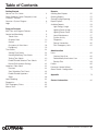
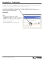
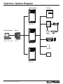
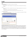
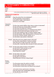
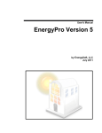
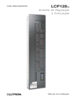
Quantum
Q-Admin Guide
®
TM
®
Table of Contents
Getting Started
How to Use This Guide . . . . . . . . . . . . . . .
Quick Reference Guide: Frequently Used
Q-AdminTM Features . . . . . . . . . . . . . . . . .
Quantum® System Diagram . . . . . . . . . . . . .
Login . . . . . . . . . . . . . . . . . . . . . . . .
4
5
6
7
Program Features
Main Tabs and Program Features . . . . . . . . . . 8
Control and Monitoring . . . . . . . . . . . . . . . 9
Tabular View . . . . . . . . . . . . . . . . . . . 9
Graphical View . . . . . . . . . . . . . . . . . 10
Control . . . . . . . . . . . . . . . . . . . . . 11
Occupancy & After Hours . . . . . . . . . . . . 16
Daylighting . . . . . . . . . . . . . . . . . . . 19
Time Clocks . . . . . . . . . . . . . . . . . . . . 23
Viewing Time Clocks . . . . . . . . . . . . . . 24
Creating/Modifying Time Clocks . . . . . . . . . 25
Testing Time Clocks . . . . . . . . . . . . . . . 30
Enable/Disable Selected Time Clocks . . . . . . 31
Review/Edit Location Settings . . . . . . . . . . 32
HyperionTM Solar Clock . . . . . . . . . . . . . . . 33
Overview. . . . . . . . . . . . . . . . . . . . 33
View Schedules/Test Events. . . . . . . . . . . 34
Enable/Disable HyperionTM . . . . . . . . . . . . 35
Setup . . . . . . . . . . . . . . . . . . . . . . 36
Load Shedding . . . . . . . . . . . . . . . . . . . 42
Diagnostics . . . . . . . . . . . . . . . . . . . . . 43
DALI Emergency Status . . . . . . . . . . . . . . . 45
Manual Tests . . . . . . . . . . . . . . . . . . . . 49
®
Reports
Creating New Reports . . . . . . . . . . . . . . . Opening Reports . . . . . . . . . . . . . . . . . .
Saving/Printing/Exporting . . . . . . . . . . . . . .
Report Options . . . . . . . . . . . . . . . . . . .
Available Reports . . . . . . . . . . . . . . . . . .
Light Energy Usage . . . . . . . . . . . . . . .
Lighting Power Usage . . . . . . . . . . . . . .
Lighting Power Trend . . . . . . . . . . . . . .
Lamp Maintenance . . . . . . . . . . . . . . .
System Activity. . . . . . . . . . . . . . . . . Diagnostics . . . . . . . . . . . . . . . . . . .
Sensor Connection . . . . . . . . . . . . . . .
DALI Emergency Units . . . . . . . . . . . . . 50
51
52
53
54
54
55
56
57
58
59
60
61
Administration
Users . . . . . . . . . . . . . . . . . . . . . . . .
Create a New User . . . . . . . . . . . . . . . Delete/Modify/Inactivate a User . . . . . . . . .
Backup Files . . . . . . . . . . . . . . . . . . Publish . . . . . . . . . . . . . . . . . . . . . . .
Processor Update Wizard . . . . . . . . . . . . . .
Green Glance® Configuration. . . . . . . . . . . . 62
62
63
64
65
69
71
Appendix . . . . . . . . . . . . . . . . . . . . . 79
Contact Information . . . . . . . . . . . . . . . 81
QuantumR Q-AdminT User Manual
3
How to Use This Guide
This guide is divided into manageable sections which will allow you to easily walk through the process of
controlling and monitoring your building using the Q-AdminT software.
You will notice that this guide contains text and corresponding pictures/screen shots.
Also note the appearance of the “indicator hand”. It will help to guide you through the process from
screen to screen. See example below:
Example Text:
Login
Upon launching the Q-AdminTM application the Login screen will
appear.
· Enter your username and password and click Login.
·C
lick Advanced to show two options, as shown on the right. These
options will allow you to publish a new database or to change your
password.
· To start Q-AdminTM in another language, click the Language
hyperlink and choose a language.
· The default login is admin/admin1.
For more on users and passwords, please see the section
Administration > Users.
4
QuantumR Q-AdminT User Manual
®
Quick Reference Guide
Frequently Used Q-AdminTM Features
This list is a quick reference guide for the most frequently used features in the Q-AdminTM software
by facility managers.
Area Scene Modification How do I modify a scene in a selected space / zone?. . . . . . . . . . . . 12
Occupancy Modification How do I modify the settings of a selected occupancy sensor? . . . . . . . . 18
If someone complains that their lights are too low
Daylight Target Set-Point Modification in a space with Daylighting, what can I do?. . . . . . . . . . 20
How do I define what lights will do (turn on / turn off / dim)
Time Clock Changes based on area occupancy and time of day? . . . . . . . . . . . . . . . . . 23
HyperionTM Solar Clock Modification How do I change the times that my shades move? . . . . . . . . 33
Diagnostics How do I know when a lamp or ballast has failed?. . . . . . . . . . . . . . . . . . . 43
What reports can I generate? How do I generate them? . . . . . . . . . . . . . . . . . . 50
Reports ®
QuantumR Q-AdminT User Manual
5
Quantum® System Diagram
Lighting Hubs
Devices
®
®
Power panels
Quantum®
processor
Ballasts
ESN Eco
Client Software
Server
LUTRON
®
®
Sensors
Q-AdminTM
control and monitor
Q-ManagerTM
server
LUTRON
LUTRON
Quantum®
processor
Keypads / Controls
Interfaces
®
®
Shades
Quantum®
processor
6
QuantumR Q-AdminT User Manual
®
Login
Login
Upon launching the Q-AdminTM application the Login screen will appear.
1. Language Selection
To start Q-AdminTM in another language, click the Language hyperlink at the top right corner and choose a
language.
2. Login
Upon launching the Q-AdminTM application the Login screen will appear, prompting for your user name and
password.
· The default login is user name “admin” and password “admin1".
· For more on user accounts and passwords, please see the section Administration > Users.
3. Advanced Login Options
Click Advanced to show two options. These options will allow you to publish a new database or to change
your password immediately after login.
Special Note to Administrator: Before launching the Q-AdminTM application, two modules must be launched on
the lighting control server. The first module is Q-RuntimeTM; this is responsible for communicating to the Quantum®
lighting processors to allow control and monitoring of the lighting system. The second module, Q-ReportingTM, is
optional, but is required to access reporting and Load Shedding features. Q-RuntimeTM and Q-ReportingTM should
be kept running at all times so system activity and energy usage will be logged. Also note that Q-ReportingTM may
not have been purchased with your system. Contact Lutron if you are interested in purchasing additional features
such as Q-ReportingTM.
®
QuantumR Q-AdminT User Manual
7
Q-AdminTM Overview
Overview
Q-AdminTM can run on a client or server PC (see Appendix for supported versions of Microsoft® Windows®).
It communicates with the Runtime and Reporting modules on the Q-ManagerTM server. The Runtime module
manages communication between the Q-ManagerTM server and the Quantum® lighting hubs, collecting all status
information (e.g., lights on/off, areas occupied/unoccupied, etc.) from the system. The Reporting module logs
system activity and power information used in reports and Green Glance®.
Up to 6 clients can access "Control & Monitoring" and "Reports" from Q-AdminTM at the same time.
Main Tabs and Program Features
The Q-AdminTM application is separated into three parts, as seen in the major tabs below:
The “Language” hyperlink at the top allows changing the language. The question mark icon to the right displays
the current version of Q-AdminTM, and the date it was released.
Control & Monitoring Overview
This tab includes features used both to control and to monitor the live state of various system features (e.g.,
lights and shades), as well as features to set up scheduled operation (Time Clock and HyperionTM Solar Adaptive
Shading), Load Shedding, and hardware diagnostics.
Reports Overview
Reports allow the building manager to gather real-time and historical information about the system.
All reports can be saved, printed, and exported to a file. Exporting to Excel format (.xls) requires Microsoft® Excel®
2003 or newer to be installed; alternatively, reports may be exported in .csv format.
Administration Overview
The Administration tab provides functions for administrators to configure and commission the system, including
user management, backup, publish and transfer, processor firmware upgrade, and Green Glance® configuration.
The Administration tab only appears for users who have been assigned the role “Admin”.
8
QuantumR Q-AdminT User Manual
®
Control and Monitoring: Tabular View
The three sub-tabs, Control, Occupancy, and Daylighting, use the same basic display, which has two options—
tabular view or graphical view (optional).
Tabular view allows you to select/view areas by selecting from a hierarchical area tree, as shown.
To select an area in tabular view, simply click the area in the tree on the left.
To change the view, click the area at the top next to “You are viewing,” and select another area. Selecting an area
under “You are viewing” will hide all other areas from the display. In the example shown, the user has selected to
only display areas on the second floor.
®
QuantumR Q-AdminT User Manual
9
Control and Monitoring: Graphical View
Graphical view allows the user to select/view areas by selecting within a graphical floorplan, as shown.
Multiple graphical pages can be used. Each page typically displays a floor in a building. Pages can be hotlinked
to each other. For example, one graphical page might be a birds-eye view of a campus, with clickable regions
for each individual building acting as hyperlinks. Each hyperlink would then take the user to another page, having
images of each floor of a building, which would then have clickable regions linking the user to graphical pages
consisting of a top view of a single floor; the user would then click on areas within the floor-view to select individual
areas to control and monitor.
To change the view, click the dropdown menu at the top next to “You are viewing,” and select another page. In the
example shown, the user has selected to display the second floor page and its associated areas.
The graphical floorplan view is an optional feature configured by Lutron. Contact Lutron Support at
1.800.523.9466 for details.
10
QuantumR Q-AdminT User Manual
®
Control and Monitoring: Control
The Control screen allows the building manager to control and monitor the lighting system as follows:
Area lights can be monitored for on/off status.
All lights in an area can be turned on/off or sent to a specific level (0-100%).
To turn all lights in an area on or off:
1. Select an area.
2. On the right pane, select the Lights tab and the Area Level subtab.
3. Click “Turn ON” or “Turn OFF” under “Quickly change area lighting".
To send all lights in an area to a level:
1. Select an area.
2. On the right pane, select the Lights tab and the Area Level subtab.
3. Select a level by typing in the box, using the slider, or using the up/down arrows.
4. Click Apply.
For areas that have been zoned:
Predefined lighting scenes can be controlled and monitored.
To send an area to a scene:
1. Select an area.
2. On the right pane, select the Lights tab and the Area Scene subtab.
3. Select a scene from the dropdown list.
4. Click Apply.
®
QuantumR Q-AdminT User Manual
11
Control and Monitoring: Control
Area lighting scenes can be modified in real-time.
To modify an area’s scenes:
1. Select an area.
2. In the right pane, click “Scene Configuration". The Scene Configuration window will open.
3. Select a scene to configure.
4. Choose whether or not zone levels should update in real-time as you are adjusting them, by selecting one of the
radio button options.
5. Change the levels of zones within the scene. This can be done either through the sliders on the left or the grid
on the right.
6. To adjust all zones in a scene at the same time, click the “Master zone level control” up/down arrows.
7. Click “Save” to save the updated scene to the system. Remember to backup the project to a .lut file
(Administration>>Backup) to save a copy to disk.
8. When finished adjusting scenes within an area, click “Close".
NOTE: Dimmable zones can be set to any intensity from 0%-100%, or to "Unaffected", which means that the
activation of the scene will not change the intensity of the zone. Non-dimmed (switched) zones can be set to On,
Off, or Unaffected.
12
QuantumR Q-AdminT User Manual
®
Control and Monitoring: Control
Levels of individual zones can be controlled and monitored.
To change a zone’s level:
1. Select an area.
2. In the right pane, select the Lights tab and the Zones subtab.
3. Select a zone.
4. Select the desired level using the slider or text box.
5. Click Apply.
Alternately, click “Turn ON” or “Turn OFF” to quickly send a zone to full on (100%) or full off (0%).
®
QuantumR Q-AdminT User Manual
13
Control and Monitoring: Control
For areas with shades, the position of shade groups can be controlled and monitored.
All shade groups in an area can be sent to open or close.
To send all shade groups in an area to open or close:
1. Select an area.
2. In the right pane, select the Shades tab.
3. Click “Select a shade preset".
4. Under “Quickly change all shades in the area,” click Open or Close to open or close all shades.
Shade groups presets can be activated and monitored.
To activate a shade group preset:
1. Select an area.
2. In the right pane, select the Shades tab.
3. Click “Select a shade preset".
4. Choose a shade group.
5. In the Preset dropdown, choose the desired preset.
6. Click Apply.
14
QuantumR Q-AdminT User Manual
®
Control and Monitoring: Control
Shade groups can be sent to a position.
To send a shade group to a position:
1. Select an area.
2. In the right pane, select the Shades tab.
3. Click “Set a shade to a position".
4. Choose a shade group.
5. Choose a position using the slider, text box, or up/down buttons.
6. Click Apply.
Many of the above actions can also be done with multiple areas selected (e.g., send all lights in multiple areas to a level,
activate the same scene in multiple areas, move all shades in multiple areas, etc.).
To select multiple areas, hold the “ctrl” keyboard button and click multiple areas.
NOTE: When controlling shades, 0% implies that the shade is closed and 100% implies that the shade is fully open.
®
QuantumR Q-AdminT User Manual
15
Control & Monitoring: Occupancy and After Hours
The Occupancy tab allows the user to view the current state of, and change settings for, occupancy and After
Hours.
Areas with Occupancy Sensors
If an area has occupancy sensors, the possible states are occupied, unoccupied, and disabled. Areas can be
grouped together, and dependency can be configured, during initial setup in Q-DesignTM. When at least one
sensor in an occupancy group is occupied, all areas in the occupancy group go to their occupied level, and
any dependent areas also go to their occupied level. When all sensors in all areas of an occupancy group go
unoccupied, all areas in the occupancy group go to their unoccupied level.
If the occupancy state is disabled, occupancy events will not be processed.
Areas without Sensors: After Hours Mode
After Hours mode is used as an "intelligent off" setting for a lighting control system. It allows occupants in a space
to continue using that space even after the prescribed "off" time while preventing the lights from being left on
needlessly. When the lights are scheduled to turn off, the user is given a visual warning (“blink-warn sequence”),
a few minutes before the lights are turned off. If occupants wish to continue using the space, they simply press a
button to keep the lights on longer. Otherwise, the lights turn off until either the system is notified that the space is
in use again or the system leaves the After Hours mode.
After Hours is useful when a space may be used after the time when the lights would normally turn off. An
example of this is found in most office buildings: If the lights were originally programmed to turn off at 6:00 p.m.,
anyone staying past that time would be in the dark when the lights turn off. Automatic shutoff can be distracting
and potentially dangerous if the occupants in a space are unexpectedly left in the dark. Additionally, lights could be
left on all night if the occupants manually turn them back on and then forget to turn them off when they leave.
When the lighting control system has an After Hours mode, the situation is quite different: Wall controls installed
throughout the space allow local control of the lights all day. At 6:00 p.m., the system time clock automatically
triggers After Hours mode. The lights perform a blink-warn sequence to tell the occupants that the system is
about to turn the lights off, and the off-delay timer starts. If the user operates one of the wall controls to indicate
continued presence, the lights will go to the requested level, the warning time will reset, and the sequence will
restart. If the off delay expires without a user operating one of the wall controls, the lights turn off. Operating a wall
control after the lights turn off will bring the lights back on and restart the warning time.
The possible After Hours states are occupied, unoccupied, disabled, and inactive.
If the state is disabled, then After Hours events are not processed.
After Hours is usually triggered from a Time Clock event, typically in the evening. The Time Clock event will change
an area’s occupancy mode to “After Hours Active".
After Hours is usually ended from a Time Clock, typically in the morning. The Time Clock event will change an
area’s occupancy mode to “After Hours Inactive". This will return the area to its “occupied” level for daytime
operation. See Control & Monitoring > Time Clock for details on setting up After Hours time clock events.
16
QuantumR Q-AdminT User Manual
®
Control & Monitoring: Occupancy and After Hours
The Occupancy screen allows the building manager (or security guard) to monitor the occupancy status of each
area and make occupancy setting changes as follows:
Current area occupancy state can be monitored (occupied, unoccupied, disabled, inactive).
Area occupancy can be disabled (or re-enabled) to override occupancy control or in case of occupancy sensor
problems.
To enable or disable occupancy:
1. Select an area.
2. In the right pane, click “Enable / Disable occupancy".
3. Select whether you want to enable or disable occupancy by choosing the appropriate radio button.
4. Select whether the area should immediately go to the occupied or unoccupied level, or do nothing.
5. Click Apply.
®
QuantumR Q-AdminT User Manual
17
Control & Monitoring: Occupancy and After Hours
Area occupancy settings can be changed in real-time.
To change occupancy settings:
1. Select an area.
2. In the right pane, click “Change occupancy settings".
3. Type in the desired occupied level, unoccupied level.
4. If the area uses sensors, choose the sensor timeout. If the area does not use sensors, choose the After Hours
Timeout and Blink-Warn Timeout.
The After Hours Timeout is the time the lights will remain on before performing a blink-warn to tell the
occupant that lights are going to turn off shortly. The Blink-Warn Timeout is the time the lights will remain
on after a blink-warn before going to off (or a custom unoccupied level) if the occupant does not press a
button on a wall control.
5. Choose whether or not the settings should take effect immediately. For example, if the area is already occupied
and you change the occupied level to 50%, should it go to 50% as soon as you click Apply, or only on the next
occupied event?
6. Click Apply.
18
QuantumR Q-AdminT User Manual
®
Control & Monitoring: Daylighting
The Daylighting screen allows a building manager to control and monitor daylighting for areas.
Daylighting is a feature in which the system changes the level of electric lights based on the amount of daylight
present. Regardless of how much daylight is coming in, daylighting works to maintain a constant level of “total
light” in a space. This “total light” is expressed as the daylighting target set point, which represents the maximum
level the electric lights will achieve when no daylight is present. Electric lights will dim down from this target set
point when daylight is present.
Quantum® also supports switched daylighting, in which an area is configured with a minimum light level. Once
total light falls below the minimum light level, the system will switch on the electric lights. An area can either use
dimmed daylighting or switched daylighting.
The Daylighting screen allows the building manager to control and monitor daylighting as follows:
Daylighting can be enabled or disabled.
To enable/disable daylighting:
1. Select an area.
2. In the right pane, click “Enable/Disable Daylighting".
3. The right pane will display the selected area’s daylighting state, and will have a button to change it.
4. Click the “Enable Daylighting” or “Disable Daylighting” button.
®
QuantumR Q-AdminT User Manual
19
Control & Monitoring: Daylighting
Dimmed daylighting: Daylight set points can be changed for each daylit area. This is particularly useful when new
departments with different lighting requirements move into a space. The daylighting target set point for an area
ranges from 0 to 100 percent.
To change the daylighting target level:
1. Select an area.
2. In the right pane, select "Adjust the Daylighting Target Set Point".
3. Change the level using the slider, text box, or up/down buttons.
4. Click Apply.
20
QuantumR Q-AdminT User Manual
®
Control & Monitoring: Daylighting
Switched daylighting: Switched daylighting is commissioned in Q-AdminTM. Minimum light level can be viewed and
set for each area.
To change the minimum light level:
1. Select an area.
2. In the right pane, select "Adjust the Daylighting Minimum Level".
3. Change the level using the text box or up/down buttons.
4. Click Apply.
®
QuantumR Q-AdminT User Manual
21
Control & Monitoring: Daylighting
To commission switched daylighting, click the “Recommission” button at the bottom of the right pane, and
perform the steps in the wizard, as follows:
Step 1: Overview – Prerequisites to commissioning switched daylighting are explained.
Step 2: Record Light Level with Lights On – Click “Turn On Lights". If necessary, click “Show Sensor Values".
Once sensor values are stabilized, click “Next” to continue.
Step 3: Record Light Level with Lights Off – This step requires a calibrated light meter. Click “Turn Off Lights” and
type in light-meter reading(s).
Step 4: Set Minimum Light Level – Enter the minimum light level that the area will maintain at all times. If desired,
use a light meter for reference.
Save: Click Save to commit the changes to the system. Remember to backup the project to a .lut file
(Administration > Backup) to save a copy to disk.
22
QuantumR Q-AdminT User Manual
®
Time Clocks
Time Clocks are defined to allow automated control of the system via programmed time clock events.
Multiple time clocks are used to separate control of different areas or different output types (lighting, shades, etc.)
You may, for example, define a separate time clock for each of the following:
) Campus Parking Lot Lights
) Shades
) Cafeteria Lights
Below is an example showing how you might define the "Campus Parking Lot Lights Time Clock":
Campus Parking Lot Lights Time Clock
1. Assign Outputs to Time Clock
I want to control all my exterior parking lot areas, which include:
) Exterior\Parking Lot 1
) Exterior\Parking Lot 2
) Exterior\Parking Lot 3
2. Define Weekly Events
During a normal week, I want my Campus Parking Lot Lights to operate as follows:
Time
Event Name
Days of the Week
One hour Before Sunrise
Turn Lights On
Monday – Friday
Sunrise
Turn Lights Off
Monday – Friday
Sunset
Turn Lights On
Monday – Friday
1:00 a.m.
Turn Lights Off
Monday – Friday
3. Define Special Events
During a holiday, I want my Campus Parking Lot Lights to operate as follows:
Time
Event Name
Sunset
Turn Lights On
10:30 p.m.
Turn Lights Off
Other Time Clock Applications
After Hours Time Clock
Time
7:00 a.m.
7:00 p.m.
Event Name
Begin After Hours
End After Hours
Disable Nighttime Occupancy Time Clock
Time
Event Name
7:00 a.m.
Disable Occupancy
7:00 p.m.
Enable Occupancy
®
Days of the Week
Monday – Friday
Monday – Friday
Days of the Week
Monday – Friday
Monday – Friday
QuantumR Q-AdminT User Manual
23
Viewing Time Clocks
To view Time Clocks, select “View Events” on the right side of the Time Clocks screen. Select a Time Clock in the
“You are viewing:” dropdown, and select a day from the calendar on the left. By default, today is selected.
All the Time Clock events for the selected day will be listed in the middle-pane. Click a different day on the left to
view that day’s Time Clock events. Click Expand All, or click the [+], to show details of all actions that will happen
when a Time Clock event is executed. On the left is the output name, and on the right is the level the output will
go to.
24
QuantumR Q-AdminT User Manual
®
Creating/Modifying Time Clocks
To create or modify a Time Clock, click “Set Up Time Clock Events” on the right, and click the “Launch Time Clock
Wizard” button.
Use Back/Next to navigate through the wizard.
At any time, press “Save and Close Wizard” when complete. Any changes made in the wizard will be saved to the
live database and to the system.
Note: After making changes, you should go to Administration and backup the project database to a file.
Step 1: Overview
Select “Show Example” to view an example Time Clock.
®
QuantumR Q-AdminT User Manual
25
Creating/Modifying Time Clocks
Step 2: Add/Edit/Delete: Add, edit, or delete Time Clocks.
Select whether you want to add, edit, or delete a Time Clock.
· To add a Time Clock, click the first radio button, type in the Time Clock name, and click Next.
· To modify a Time Clock, click the second radio button, click the Time Clock to modify, and click Next.
To delete a Time Clock, click the third radio button, select the Time Clock to delete from the dropdown menu, and
click Delete.
26
QuantumR Q-AdminT User Manual
®
Creating/Modifying Time Clocks
Step 3: Assign Outputs
Define which system loads, shades, and other outputs are controlled by the selected Time Clock. The text box at
the top allows you to change the name of the Time Clock.
To assign outputs to a Time Clock:
1. Click “Add/Remove Output” to display a window with all controllable outputs in the project database.
2. To add outputs:
a. Select the type of output in the dropdown.
b. Navigate to the output in the area tree.
c. Check the output you want to add.
3. Click OK when finished.
The grid below the “Add/Remove Output” link shows what outputs are selected for control by the selected Time
Clock.
®
QuantumR Q-AdminT User Manual
27
Creating/Modifying Time Clocks
Step 4: Define Weekly Events
Weekly events occur regularly every week, based on the selected weekdays—for example, an event can be set to
occur every Monday, Wednesday, and Friday.
To add a new event:
1. Click “New Event". The bottom of the screen will populate with event details. Each output assigned to the Time
Clock will appear in the event list.
2. Define the event name, what days and times the event will happen on, and what actions will happen in the
system when the event executes. The “time” dropdown allows you to choose either a fixed time (e.g., 5:41
p.m.) or an astronomic time (e.g., 12 minutes after sunset).
3. The grid in step 2 shows what level each output will be sent to. (The default, “unaffected,” means that output
will not be affected by the Time Clock event.) To quickly set many different outputs to the same level (e.g., all
areas to scene 1), click the “Quickly Set Levels” hyperlink. In the window that displays, choose the output type
in the first dropdown menu, and choose the level in the second dropdown menu.
4. The evaluate checkbox is valid only for occupancy. If evaluate is checked the Time Clock event enables/
disables occupancy, it will first re-evaluate if the area is occupied and go to the appropriate level; if unchecked,
lights will not change until the next occupancy event (and if occupancy is enabled).
5. When finished adding an event, click “Save” (you may have to scroll down to see this button).
28
QuantumR Q-AdminT User Manual
®
Creating/Modifying Time Clocks
Step 5: Define Special Events
Special events are events that will occur on specific dates, such as holidays or once-a-month occurrences.
Normal weekly events will still occur on days that are not part of a special schedule.
To define special events:
1. Click on “Show Special Calendar” to modify the schedule.
2. In the yearly calendar, select or unselect days by clicking them, to add or remove from the special schedule. A
single day in the year may only be part of a single special schedule. Special schedules will recur on the same
date every year.
3. After creating a special schedule, click “Save,” and then add events as before. Up to five special schedules can
be defined. Special schedules are unique to the Time Clock they are defined in. E.g., the Holiday schedule in
one Time Clock may be different than the Holiday schedule of another Time Clock.
Step 6: Click “Save and Close Wizard”
“Save and Close Wizard” will make the Time Clock changes to the live Quantum® system. To make the changes in
the .lut file, remember to perform a project database backup in the Administration tab.
®
QuantumR Q-AdminT User Manual
29
Testing Time Clocks
Test Events allows you to simulate a Time Clock event live to confirm that it controls the outputs programmed to it.
To test a Time Clock event:
1. Select a Time Clock event in the grid.
2. Click the “Test Event” button.
30
QuantumR Q-AdminT User Manual
®
Enable/Disable Selected Time Clocks
Time Clocks can be enabled and disabled through the system (e.g., through keypad button presses, CCI toggle switches,
or sequences). These are programmed in Q-DesignTM after a Time Clock has been created in Q-AdminTM. Once a Time
Clock is disabled, all Time Clock events for the given Time Clock will stop occurring until that Time Clock is re-enabled.
To disable an enabled Time Clock indefinitely:
1. Choose a Time Clock in the “You are viewing:” dropdown.
2. Choose the “Enable/Disable Selected Time Clock” option in the right pane.
3. Choose the “Until I Enable It Again” option in the right pane.
4. Click “Disable Time Clock". The Time Clock will remain disabled until explicitly re-enabled.
To disable an enabled Time Clock until the end of the day:
1. Choose a Time Clock in the “You are viewing:” dropdown.
2. Choose the “Enable/Disable Selected Time Clock” option in the right pane.
3. Choose the “Until the End of the Day” option in the right pane.
4. Click “Disable Time Clock". The Time Clock will remain disabled until 11:59 p.m. It will then be automatically
re-enabled.
To enable a disabled Time Clock:
1. Choose a Time Clock in the “You are viewing:” dropdown.
2. Choose the “Enable/Disable Selected Time Clock” option in the right pane.
3. Click “Enable Time Clock".
®
QuantumR Q-AdminT User Manual
31
Review/Edit Location Settings
The “Location Settings” display is used for configuring geographical position and time zone.
The following system features are affected by location settings:
· Night Lights – Can be programmed to begin or end based on sunrise/sunset.
· Time Clocks – Can be programmed to execute based on sunrise/sunset.
· HyperionTM – Uses location settings and time zone information to determine the precise position of the sun.
· Green Glance® – Uses location settings for weather display.
The “Location Settings” display can be accessed from the Time Clock and HyperionTM screens, by clicking “Edit
Location Settings” in the right pane after selecting “Review Location Settings".
To enter your location:
1. Click “Edit Location Settings,” and in the popup window, select your country, state/province, and city. This will
automatically populate your latitude, longitude, time zone, and daylight savings information.
2. If your city is not available, click “Add City” and enter the appropriate details.
3. Click “Save” when completed. Remember to perform a database backup (see the Administration section for
details) to save changes to disk.
32
QuantumR Q-AdminT User Manual
®
HyperionTM Solar Clock
Overview
HyperionTM is an automated shading system that adjusts Sivoia® QS shades throughout the day based on the
sun’s position. The shades reduce glare and solar heat gain in the space, creating a comfortable and productive
work or learning environment. HyperionTM maximizes the amount of available daylight entering a space, enhancing
the energy-saving potential of daylight-harvesting lighting systems, and can also reduce energy costs associated
with HVAC systems.
Screen Layout
The HyperionTM Solar Clock screen allows the user to view and test the HyperionTM schedule for any area, enable/
disable HyperionTM, and to configure HyperionTM settings.
The screen layout is similar to the Time Clock screen: On the left, a calendar is used to select different days. In the
middle is a full list of HyperionTM events for that day, which displays when shades move, and what level they move
to. On the right pane, radio buttons are used to view settings, setup HyperionTM, test HyperionTM events, enable/
disable HyperionTM, and review location settings.
®
QuantumR Q-AdminT User Manual
33
HyperionTM Solar Clock
To view HyperionTM Schedules:
1. Select “View settings” on the right side of the HyperionTM screen.
2. Select an area in the area dropdown.
3. Select a day from the calendar on the left (by default, today is selected).
All the HyperionTM events for the selected day will be listed in the middle-pane. Click a different day on the left
to view that day’s HyperionTM events. Click Expand All, or click the [+], to show details of all HyperionTM shade
movements that day.
To Test a HyperionTM Event:
Testing HyperionTM events allows the user to simulate the selected HyperionTM event live to confirm that it controls
the correct shade group(s) in the expected manner.
1. Choose the “Test HyperionTM Events” in the right pane.
2. Select an area in the area dropdown.
3. Click the HyperionTM event you want to test.
4. Click “Test HyperionTM Event". The shades in the area will go to the levels defined in the HyperionTM event.
34
QuantumR Q-AdminT User Manual
®
HyperionTM Solar Clock
To Enable/Disable HyperionTM:
1. Choose “Enable/Disable HyperionTM” in the right pane.
2. Select an area in the area dropdown.
3. Select whether you want to enable HyperionTM, disable HyperionTM until the end of day, or disable HyperionTM
until it is manually re-enabled.
4. Click “Apply to current area” to enable/disable only the selected area’s HyperionTM schedule, or “Apply to all
areas” to enable/disable HyperionTM for the entire project.
Shades controlled by HyperionTM can also be controlled manually. Anytime a HyperionTM controlled shade moves
due to manual control, the HyperionTM schedule is overridden temporarily.
HyperionTM can also be enabled and disabled through the system (e.g., through keypad button presses, CCI
toggle switches, Time Clock events, or sequences).
®
QuantumR Q-AdminT User Manual
35
HyperionTM Solar Clock
Setup HyperionTM
To configure HyperionTM, select “Setup HyperionTM” in the right pane, and click “Launch HyperionTM Wizard". The
HyperionTM Wizard can be used to configure HyperionTM in multiple areas.
HyperionTM Wizard Step 1: Overview and Defaults
Set system-wide defaults for HyperionTM. This is a quick way to change the settings for all areas that use the
defaults.
· Work-surface height and maximum sunlight penetration define how far into the space direct sunlight will be
allowed to penetrate. HyperionTM will continually adjust shades to ensure direct sunlight does not exceed the
maximum sunlight penetration depth at the work-surface height.
· Minimum time between shade movements defines how often HyperionTM moves shades automatically. To
minimize distractions, the time between movements defaults to 60 minutes.
36
QuantumR Q-AdminT User Manual
®
HyperionTM Solar Clock
HyperionTM Wizard Step 2: Facing Directions
Specify the different facing directions present in your building(s). These are the various different compass
orientations of any sides of your building(s) that will have shades controlled by HyperionTM. Facing directions are
used to determine how the sun will penetrate into an area during any given time of a particular day. It is important
to measure facing directions correctly, as all HyperionTM shade movements will be based on these directions. For
best results, be sure to measure your facing directions using true north rather than magnetic north.
®
QuantumR Q-AdminT User Manual
37
HyperionTM Solar Clock
HyperionTM Wizard Step 3: Window Types
In order to figure out how light will penetrate into each space, we need to know the size and relative position from
the floor for each window. For most buildings, a few window sizes and positions are used. We call these “window
types". Enter in the window types (Size and relative position from the floor) that will be used for HyperionTM
controlled spaces.
38
QuantumR Q-AdminT User Manual
®
HyperionTM Solar Clock
HyperionTM Wizard Step 4: Area Setup
For each area controlled by HyperionTM, choose the appropriate Facing Direction. For areas with multiple façades
(e.g., a corner office), you can select a different facing direction for each shade group. For each shade group,
select the window type covered by the shades. Additionally, a visor position can be set for each shade group.
The visor position is the maximum open position shades should move to during the day. The default visor position
is full open (100%). A visor position helps to reduce glare from other indirect light sources (e.g., a neighboring
building).
To change HyperionTM area settings:
1. Select each area in the top grid, and the bottom grid will be populated with that area’s shade groups.
2. For each shade group in an area, set the checkbox at the right if the shade group will be affected by HyperionTM.
3. If a shade group is affected by HyperionTM, set the window type, facing direction, and visor position.
By default, the settings from step 1 will be used, but for any area, you may choose to use different settings by
clicking “Customize the HyperionTM settings for this area” at the bottom. This will allow you to choose a worksurface height, maximum sunlight penetration, and minimum time between movements specific to that area.
®
QuantumR Q-AdminT User Manual
39
HyperionTM Solar Clock
HyperionTM Wizard Step 5: Nighttime Settings
Specify when the HyperionTM schedule will begin and end every day. Outside of these times, HyperionTM will not
move the shades. Times can be set either as fixed times (e.g., 5:35 a.m.) or as astronomic times (e.g., at sunrise,
30 minutes before sunset, etc.).
Set what should happen when the HyperionTM schedule ends every day: open all shades, close sheers
(sunscreens) only, close sheers (sunscreens) and open blackouts, or leave shades unaffected (in which case
shades will stay where they are when HyperionTM ends).
40
QuantumR Q-AdminT User Manual
®
HyperionTM Solar Clock
HyperionTM Wizard Step 6: Override Settings
Any manual movement of a shade in an area will disable the HyperionTM schedule in an area. Select whether to
disable the HyperionTM schedule for a fixed time, or for the rest of the day, when a manual override occurs.
Save and Close Wizard will save the HyperionTM schedule to the live database and transfer the information to all
processors in the system. To save changes to disk, see the “Administration > Backup” section.
Once finished, view and test the new schedule. If any changes are required, you may revisit the HyperionTM Wizard
and tweak any settings as desired.
®
QuantumR Q-AdminT User Manual
41
Load Shedding
Load shedding allows the building manager to monitor whole building lighting power usage and apply a load shed
reduction to selected areas, thereby reducing a building’s peak power usage. Load shedding can be done for the
whole project, for groups of areas, or for individual areas, at levels between 0% and 90%. 0% is the same as no
load shedding.
To change load shedding targets for areas:
1. Choose an area using the area tree in the grid on the right side.
2. Select the “Allow Load Shed” checkbox to load shed the area, or deselect it to prevent the area from being load
shed.
3. Type a number (from 0 to 90) in the Goal column. This is the percentage of the lighting level you want to reduce
the area by (0% = no reduction; 90% = maximum reduction).
4. Repeat for other areas for which you want to change load shedding.
5. Click "Save & Apply".
To enable/disable load shedding:
1. Click "Enable Load Shed" to enable load shedding for the entire project. The button text will change to “Disable
Load Shed".
2. Click “Disable Load Shed” to disable load shedding for the entire project. The button text will change to “Enable
Load Shed".
Typing a new number in the “Set Demand Goal to:” textbox changes the demand goal (red line). This represents a
reference line for the building manager. When building power usage gets close to or above the line, adjust the load
shedding for various areas to higher percentages to reduce demand.
42
QuantumR Q-AdminT User Manual
®
Diagnostics
Diagnostics allows the building manager to check on the status of all equipment in the lighting control system.
View Diagnostics
Devices will be listed with a reporting status of OK, missing, or unknown. Check or uncheck the filters above the
grid (OK, Unknown, Not in Database, Not Responding) to show or hide devices with those states. At any time,
click the “Show Report” link above the grid to show the same information in a report form, which can be saved,
exported to Excel or .csv formats, and printed.
To view what devices are currently not responding:
1. Make sure the Not Responding checkbox is checked at the top of the screen. All other checkboxes can be
unchecked to filter the list to only non-responding devices.
2. Use the diagnostics tree to navigate to which devices are currently Not Responding, or click Expand All to show
all devices.
3. To generate a report that can be printed or saved, click on “Show Report".
®
QuantumR Q-AdminT User Manual
43
Diagnostics
Lighting Hubs
Devices
®
®
Power panels
Quantum®
processor
Ballasts
ESN Eco
Client Software
Server
LUTRON
®
®
Sensors
Q-AdminTM
control and monitor
Q-ManagerTM
server
LUTRON
LUTRON
Quantum®
processor
Keypads / Controls
Interfaces
®
®
Shades
Quantum®
processor
Diagnostics are organized by communications connections to the system in the following hierarchy:
1. Manager Server: The Q-ManagerTM server runs the Q-AdminTM software and connects to Quantum® hubs.
These hubs are typically located in equipment closets on each floor of the building.
2. Q
uantum® Hubs: Quantum® hubs contain central processors that connect to lighting-control devices on each
floor. These controls include backroom equipment installed in electrical closets, ceilings, or floors, such as
ballast controllers, power panels, and integration interface equipment. Controls connected to the Quantum®
hub that are located in the occupant space include wall controls and shades.
3. Ballast Controllers: Ballast controllers connect to ballasts and sensors located in fixtures throughout a section of
a floor. Typically, one ballast controller will control up to 128 ballasts.
44
QuantumR Q-AdminT User Manual
®
View DALI Emergency Status
The “View DALI Emergency Status” section of the Diagnostics screen allows the user to configure and monitor tests for
DALI emergency units.
This feature will be displayed if the Quantum® system includes DALI Emergency units.
Two types of tests are run for DALI emergency ballasts:
1. Functional Test – This is a short test that verifies emergency units are responding properly and lamps have not failed.
2. Duration Test – This is a longer test that verifies that batteries driving emergency units are operating properly.
The calendar shows all days in which test runs are scheduled. Hovering over a highlighted day shows what specific tests
(functional, duration, or both) are happening for which ballast test groups.
To show the last date function or duration tests were run for each unit:
1. Click “Customize Columns…”
2. Select the columns you want to be displayed in the grid.
To define groups, click the “Setup Wizard” link on the Diagnostics screen. This will open the DALI Emergency Setup
Wizard.
To view a printable report, click the “Show Report” link above the grid.
®
QuantumR Q-AdminT User Manual
45
DALI Emergency Status Setup
Step 1: Define Emergency Groups
The system provides seven groups of ballasts, which allows, for example, testing each group on a particular day
of the week. The user can let the system define which ballasts are in which groups (default), or the user can define
groups manually, by entering a group number for each ballast.
To add a ballast to a specific DALI emergency test group:
1. Select “Let me Define Emergency Groups".
2. Select a ballast in the grid.
3. Type in the group number from 1 to 7.
46
QuantumR Q-AdminT User Manual
®
DALI Emergency Status Setup
Step 2: Setup Test Times
The Setup Test Times step determines what weekday and time of day each test group will be tested, and how
often function and duration tests should be run.
To define which day of the week each emergency group is to be tested:
1. Change the value in the weekday dropdown to choose which day of the week a group is tested.
2. Type in a time of day to determine what time a group is tested. Choose a day and time when the space is
unlikely to be occupied. Light levels will be affected during function and duration tests.
To define how often function and duration tests should be run, select the appropriate radio button.
Function tests can be set to run weekly (default), every other week, monthly, or manual only.
Duration tests can be set to run monthly (default), quarterly, every 6 months, annually, or manual only.
If both a function and duration test are scheduled on the same day for a particular test group, only the duration
test will run, as each duration test also performs a functional test.
®
QuantumR Q-AdminT User Manual
47
DALI Emergency Status Setup
Step 3: Configure Prolong Time
Prolong time is the time emergency units should continue to remain at their emergency level after normal power is
restored. This prevents lights switching on/off multiple times when power intermittently goes in and out.
To configure prolong time, select the radio button matching the desired prolong time.
48
QuantumR Q-AdminT User Manual
®
Manual Tests
To run a manual test:
1. Select a ballast within the group in the grid (optional).
2. Click “Manual Test".
3. Select the type of test to run (function test or duration test).
4. Choose “Selected Emergency unit” to test the specified ballast (as selected on the diagnostics screen).
Otherwise, choose “Emergency Units part of the following groups” and check which groups to test.
5. Click “OK” to begin the test.
To stop any test on a group (manual or scheduled):
1. Click any ballast in the group.
2. Click “Stop All Tests".
®
QuantumR Q-AdminT User Manual
49
Reports
Creating New Reports
Reports allow the building manager to gather real-time and historical information about the system, including
power usage, lamp, device, and sensor status, and system activity.
To run a new report:
1. Click “New” under the Reports tab.
2. Click the type of report desired in the “Standard Reports".
3. Click “OK". A new page will load for the new report.
4. Select the report options (filters) and click Apply.
50
QuantumR Q-AdminT User Manual
®
Reports
Opening Reports
To open a saved report:
1. Click “Open” in the Reports tab.
2. Click the selected report.
3. Click “OK". The report will be loaded in a new subtab under the “View” tab.
®
QuantumR Q-AdminT User Manual
51
Reports
Saving, Printing, and Exporting Reports
Reports can be printed and saved to files. Exporting to Excel format (.xls) requires Microsoft® Excel® 2003 or
newer to be installed; alternatively, reports may be exported in .csv format. All reports can be exported in tabular
format (to .xls or .csv). Only reports that have a graphical view can be exported to the .jpg image format.
To save a report that has been created:
1. Click “Save” or “Save As".
2. If saving for the first time (or doing Save As), you will be prompted for the report name. Change the default
name if desired, and click Save.
To print a report:
1. Click “Print".
2. Select the desired printer, choose options if desired, and click “OK".
To save a report to a file:
1. Click “Export".
2. Select the desired output format (Excel spreadsheet, JPEG image, or CSV spreadsheet).
3. Choose the output filename by typing in the text box and/or using the “Browse…” button.
4. To open the file afterward in the default spreadsheet or image application, check “Open file after Export".
5. Click “Export.
52
QuantumR Q-AdminT User Manual
®
Reports
Report Options
Reports can be run with different options—for example, the report above can be run for one or more areas over a
specified time period.
To choose areas displayed in a report:
1. Click “Click here to select Areas…”
2. Check one or more areas in the area tree.
3. Click “OK".
To change other options in reports, use the appropriate controls on the right panel. Available options vary by
report.
®
QuantumR Q-AdminT User Manual
53
Available Reports
Lighting Energy Usage Report – “How much energy did the lighting in [selected areas] use over [time period]?”
This report shows a pie chart comparing multiple areas over time. It can be used to find which areas are using the
most energy.
To create a Lighting Energy Usage Report:
1. Select the areas to compare by using the “Click here to select Areas…” link.
2. Choose the timeframe by using the dropdown menu on the right.
3. Click “Apply".
54
QuantumR Q-AdminT User Manual
®
Available Reports
Lighting Power Usage Report – “How does the power usage of [selected areas] compare over [time period]?”
This report shows a bar graph comparing multiple areas’ energy usage over time.
To create a Lighting Power Usage Report:
1. Select the areas to compare by using the “Click here to select Areas…” link.
2. Choose the timeframe by using the dropdown menu on the right.
3. Click “Apply".
®
QuantumR Q-AdminT User Manual
55
Available Reports
Lighting Power Trend Comparison Report – “How does the power usage of [selected area] compare over
[selected time frames]?”
This report shows power usage for a particular area over two different time spans. For example, this can be used
to compare energy of this week with last week.
To create a Lighting Power Trend Comparison Report:
1. Select the area by using the dropdown menu on the right.
2. Choose the first date by using the “Time Frame A Start Date” dropdown menu.
3. Choose the second date by using the “Time Frame B Start Date” dropdown menu.
4. Select the time span in the “Duration” dropdown menu.
5. Click “Apply".
56
QuantumR Q-AdminT User Manual
®
Available Reports
Lamp Maintenance Report – “Which Areas are reporting failed lamps?”
This report, run against a specified area, lists the number of failed lamps in that area or (if it is a folder area), the
number of failed lamps in each of its child areas. Areas with no failures are not displayed.
To create a Lamp Maintenance Report:
1. Select an area in the dropdown.
2. Click “Apply".
®
QuantumR Q-AdminT User Manual
57
Available Reports
System Activity Report – “What activity occurred in [selected areas] over [time period]?”
This report gives a list of activity that has happened in the Quantum® system (or in specified areas) over a given
period of time. The report will display all events of the specified types that happened in the specified areas within
the date range. Activity filters are as follows:
· Occupant Activity: Areas going occupied/unoccupied; wall controls being pressed
· Time Clock Activity: Time Clock events being executed
· Building Manager Activity: Q-AdminTM activity, including login/logout, and real-time changes to the lighting
system.
· Status Activity: Zone level changes, area scene changes, etc.
· Device Failure Activity: Devices becoming unresponsive
· Lamp Failure Activity: Lamp failures reported by EcoSystem®/DALI ballasts
· Sensor Activity: Occupancy sensor state changes (occupied and unoccupied)
· Ballast Failure / Auto Replacement Activity: Shows when ballast failures have occurred or when new ballasts
have been installed and auto-replaced
· System Errors: Error codes reported by the system
· BACnet Activity: Lights, shades, and other system objects changed through BACnet
To create a System Activity Report:
1. Select one or more areas by using the “Click here to select Areas…” link.
2. Choose the time span for which to display activity by using the “over the…” dropdown menu. If selecting
“Custom,” specify the start date and end date.
3. Select the desired activity types to show by clicking the checkboxes under “Filter Events".
4. Click “Apply".
58
QuantumR Q-AdminT User Manual
®
Available Reports
Diagnostics Report – “What devices are currently not responding and need attention?”
The Diagnostics Report displays the same information found in the Diagnostics screen. Devices (e.g., keypads,
shades, power panels) are listed with their current status (unknown, not responding, not in database, or OK).
To create a Diagnostics Report:
1. Select one or more areas by using the “Click here to select Areas…” link.
2. Select the desired status types to show by clicking the checkboxes under “Show devices with status".
3. Click “Apply".
®
QuantumR Q-AdminT User Manual
59
Available Reports
Sensor Connection Report – “What sensors are not properly connected?”
This report shows the state of wired sensors (occupancy, IR, and photo), as unknown, not connected, not in
database, or connected.
To create a Sensor Connection Report:
1. Select one or more areas by using the “Click here to select Areas…” link.
2. Select the desired status types to show by clicking the checkboxes under “Show Sensor whose Status is".
3. Click “Apply".
60
QuantumR Q-AdminT User Manual
®
Available Reports
DALI Emergency Units Report
The DALI Emergency Units Report allows the user to view, export, and print the status of DALI emergency units.
To create a DALI Emergency Units Report:
1. Select one or more areas by using the “Click here to select Areas…” link.
2. Select the desired status types to show by clicking the checkboxes under “Show devices with status".
3. Click “Apply".
®
QuantumR Q-AdminT User Manual
61
Administration: Users
The Users screen allows new user accounts to be created and existing user accounts to be edited.
There are two user roles: Regular and Admin. Regular users do not have access to the Administration tab.
To create a new user:
1. Click “Add".
2. Fill in the text fields on the right. “First Name” and “Last Name” are optional.
3. Select the user’s role.
4. Click “Reset account password".
5. Enter, and confirm, the desired password.
6. If desired, check “Ask for password change at next login".
7. Click “Save Changes".
...continued on next page
62
QuantumR Q-AdminT User Manual
®
Administration: Users
To delete a user:
1. Select an existing user in the grid.
2. Click “Delete".
To modify a user:
1. Select an existing user in the grid.
2. Fill in the text fields on the right. “First Name” and “Last Name” are optional.
3. Select the user’s role.
4. Click “Reset account password".
5. Enter, and confirm, the desired password.
6. If desired, check “Ask for password change at next login".
7. Click “Save Changes".
To inactivate a user:
1. Select an existing user in the grid.
2. Uncheck “User account active".
3. Click “Save Changes".
®
QuantumR Q-AdminT User Manual
63
Administration: Users
The Backup screen allows an admin user to save the project database and/or graphical floorplan. It is very
important, after making any configuration change, to perform a backup of the project database.
Actions that modify the project and require a backup to save changes include the following:
· Scene Configuration
· Changing default occupancy, After Hours, or daylighting levels
· Daylight commissioning
· Configuring Time Clocks
· Configuring HyperionTM
· Configuring DALI emergency tests
· Modifying user accounts
· Modifying Green Glance® Configuration
To backup the live project and/or graphical floorplan file:
1. Check “I want to back up the project database” (if desired).
2. Choose the destination file by using the “Browse…” button and/or typing in the textbox.
3. Check “I want to back up the graphical floor plan” (if desired).
4. Choose the destination file by using the “Browse…” button and/or typing in the textbox.
5. Click “Save".
64
QuantumR Q-AdminT User Manual
®
Administration: Publish
Publish Project Files: Choose a File
The Publish screen allows an administrator to publish a project (.lut file) to the lighting control system. The project file is
created using Q-DesignTM and contains the configuration for a system, including lighting zones, keypad programming,
daylight settings, occupancy settings, nightlight settings, etc. The user can either republish the current file, which will
simply perform a full transfer to the system, or the user can choose to publish a new file before transferring to the
system. Note: When transferring a new configuration to the system, local controls (e.g., keypads, occupancy sensors,
daylight sensors, etc.), will not function. Transfers typically take between 15 and 45 minutes to complete.
To choose a project to publish:
1. Under “Project Database,” choose the second radio button specify that you want to choose a file.
2. Choose the existing file to load by using the “Browse…” button and/or typing in the textbox.
To choose a graphical floorplan to publish:
1. Under “Graphical Floor Plan,” choose the second radio button specify that you want to choose a file.
2. Choose the existing file to load by using the “Browse…” button and/or typing in the textbox.
By default, the first radio buttons are selected for both project and graphical floorplan. In this case, the published
file will remain the same.
To choose to remove a published graphical floorplan:
1. Select the third radio button (“I do not want to use a graphical floorplan”).
2. To proceed with the publish, click “Next".
®
QuantumR Q-AdminT User Manual
65
Administration: Publish
Publish Project Files: Transfer to Server
Publishing a database will cause all other clients (i.e., Q-AdminTM and Green Glance® on any clients, and the
Reporting Server on the server) to restart.
Click “Start” to perform the publish. This will load the files to the runtime module on the server.
To perform a database transfer to the lighting system, click “Next” to proceed to the “Select Systems” screen.
If you do not wish to transfer to the lighting system, click “Cancel.” This will reload Q-AdminTM with the newly
published file. This should only be done if changes have been made to the graphical floorplan.
66
QuantumR Q-AdminT User Manual
®
Administration: Publish
Publish Project Files: Select Systems
The Select Systems screen displays the state of the processors in the project, in preparation for a database
transfer. All the processor systems (“hubs”) in the project file are listed, each with one of three states:
· A green checkbox indicates the processor hub is ready for transfer.
· A red “X” indicates at least one processor in the hub is unable to communicate.
· A yellow “!” indicates the processor hub needs to be upgraded to the latest firmware prior to transfer. To perform
a processor upgrade, use the Processor Update Wizard screen.
If the “Audit Check” checkbox is checked, database programming will be checked for potential problems at the
beginning of the transfer.
To select which processor systems to transfer to, check one or more responding systems and click “Next".
®
QuantumR Q-AdminT User Manual
67
Administration: Publish
Publish Project Files: Transfer to System
To begin the transfer process, click “Start". If the Audit Check is enabled, it will scan the database for both critical
errors and warnings. If there are any problems detected, these will be displayed to the user in a popup, with
options to print or export the details. If there are warnings but no critical errors, the user can choose to proceed
with transfer or to cancel. A critical error in an audit check will prevent transfer.
After the audit completes (if selected), the live database will be transferred (i.e., uploaded) to all the processor
systems that were selected on the Select Systems page.
Note: When transferring a new configuration to the system, local controls (e.g., keypads, occupancy sensors,
daylight sensors, etc.), will not function. Transfers typically take between 15 and 45 minutes to complete.
Once the transfer is complete, please review the display for any errors. If there are errors, you may need to check
system wiring and configuration, or correct the project file in Q-DesignTM.
While the update is in progress, all other tabs will be disabled. After a publish or transfer, Q-AdminTM will need to
be restarted.
68
QuantumR Q-AdminT User Manual
®
Administration: Processor Update Wizard
Processor Update Wizard: Select Systems
The Processor Update Wizard is used to update processors in the lighting control system to the latest firmware
version. This is done when upgrading the lighting system to allow for new functionality and to support newly
released Lutron® products.
Note: During the processor firmware upgrade, local controls (e.g., keypads, occupancy sensors, daylight sensors,
etc.), will not function. After the upgrade completes, a "publish" should be performed for the system to operate.
A system can only be upgraded if all the processors assigned to it are responding.
To update processor firmware, check one or more responding systems and click “Next.”
®
QuantumR Q-AdminT User Manual
69
Administration: Processor Update Wizard
Processor Update Wizard: Update Processors
The “Update Processors” screen displays the progress of the processor firmware upgrade.
While the update is in progress, all other tabs will be disabled.
70
QuantumR Q-AdminT User Manual
®
Administration: Green Glance® Configuration
Administrators can use the Green Glance® Configuration to set up how the Green Glance® application will work.
After any changes are saved, Green Glance® should be restarted.
Green Glance® Configuration: Areas Displayed
The “Areas Displayed” tab allows an administrator to define the areas to be displayed in Green Glance®.To change
the name of the building as displayed in Green Glance®, type the desired name under “Building Name".
To choose which areas are displayed in Green Glance®:
1. Click “Click here to select Areas…” The “Select Additional Areas” pop up will display, as shown.
2. Expand the area tree as necessary, and select the desired areas using the checkboxes.
3. Click “OK".
To change the name of an area as displayed in Green Glance®, type the desired name in the column
“Green Glance® Area Display Name".
®
QuantumR Q-AdminT User Manual
71
Administration: Green Glance® Configuration
Green Glance® Configuration: Display Control
“Display Control” allows an administrator to configure Green Glance® default behavior.
To set the default page that loads when Green Glance® starts, select an option under “Default Page on Start Up".
If “Enable auto-cycle” is checked, Green Glance® will automatically move from one screen to the next, based on
the ordering of the pages listed in “Pages To Be Cycled".
Select an option in the “Cycle Time” dropdown menu to choose how often Green Glance® should stay on each
page while cycling.
72
QuantumR Q-AdminT User Manual
®
Administration: Green Glance® Configuration
Green Glance® Configuration: Savings Comparison
Green Glance® displays energy savings in terms of kWh (real power), money, coal not burned, and carbon dioxide
not emitted. Green Glance® can be set to use some, none, or all of these comparisons, based on which are in the
“Comparisons To Be Displayed” box. Money saved is determined by price of electricity and unit of currency, which
can be set at the bottom of the screen.
®
QuantumR Q-AdminT User Manual
73
Administration: Green Glance® Configuration
Green Glance® Configuration: Weather Display
Determine whether or not Green Glance® will display the current local weather, and set the project location using
the “Edit Location Settings” button.
Weather display requires Internet connectivity in order to connect to the Lutron® Weather Server.
74
QuantumR Q-AdminT User Manual
®
Administration: Green Glance® Configuration
Project Info
Enter information relevant to the project, including commission date, title, website, and description; and upload a
building thumbnail and image. These will be displayed to the user in the Project Information tab of Green Glance®,
unless the user unchecks “Display the Project Information Tab".
This information is displayed in Green Glance® for informational purposes.
®
QuantumR Q-AdminT User Manual
75
Administration: Green Glance® Configuration
Building Features
The user can type in building features to display to the user in Green Glance®. This information is displayed in
Green Glance® for informational purposes.
76
QuantumR Q-AdminT User Manual
®
Administration: Green Glance® Configuration
Design Team
The user can type in the names of the building design team to display to the user in Green Glance®. This
information is displayed in Green Glance® for informational purposes.
®
QuantumR Q-AdminT User Manual
77
Notes
78
QuantumR Q-AdminT User Manual
®
Appendix - Quantum® Overview
1 Overview
Quantum® Total Light Management is a suite comprised of several applications, as follows:
) Q-DesignTM: - Used to set up and commission a lighting system.
) Q-GraphicTM: - Used to overlay graphical floorplans onto Q-DesignTM databases.
) Q-AdminTM: - Used for daily control, monitoring, and reports on a lighting system.
) Green Glance®: - Used to monitor energy savings and compare trends.
) Q-RuntimeTM: – Allows Q-AdminTM to communicate to lighting system.
) Q-ReportingTM: – Logs historical data. Required for Green Glance® to run, and for Q-AdminTM to use Load
Shedding and Reports.
2 System Hardware
Quantum® supports the following hardware:
) Quantum® processors
- Two configurable device links per processor.
- Maximum of 16 processors per “sub-system". Typically each floor in a building is a sub-system.
- Maximum of 128 “sub-systems” per Quantum® project.
) Lutron® Digital Ballast Interfaces (DBI) to control EcoSystem® loads
) Lutron® Power Panel devices (GP, LP, XP)
) Lutron® wired QS Devices
- Energi Savr NodeTM (All varieties: DALI, EcoSystem®, 0-10V, and Switching)
- Keypads
- Keyswitches
- Shades and shade power supplies
- GRAFIK Eye® (Triac, EcoSystem®, and DALI, both RF and non-RF)
- NWK (Ethernet Interface)
- IO (10 wired contact closure pins – 5 input, 5 output)
- QSE-DMX
- QSM (Wireless-only, wired-only, and wired+wireless combo units)
- IR-Eye infrared sensor
) All Lutron® EcoSystem® ballasts and drivers (with appropriate EcoSystem® hub)
) All DALI-compliant dimmable ballasts (with appropriate Lutron® DALI hub)
) Lutron® wired and wireless occupancy and daylight sensors
) Lutron® wired IR sensors
) Lutron® wireless Pico® controllers
3 Third-Party Interfacing
Quantum® supports several options for third-party interfacing:
) BACnet over IP
- One Quantum® processor in each system exposes system objects (at user’s discretion) to third-party
BACnet-compatible software.
- Typically used to integrate Lutron® lighting into third-party building management software.
) RS232/Ethernet Integration
- QSE-CI-NWK in Quantum® system provides integration through RS232 (serial port) or Ethernet.
- Typically used to receive commands from third-party devices, such as touchscreens.
) Contact closures
- The QSE-IO device can send maintained or pulsed signals over its contact-closure outputs. A third-party
system can take these as input.
- The QSE-IO and QS keypad can receive maintained (open/close) inputs and perform various system
actions accordingly.
®
QuantumR Q-AdminT User Manual
79
Appendix - Quantum® Overview
4 Installation Prerequisites
Languages:
) Quantum® supports the following languages:
- English (US)
- Spanish
- French
- German
- Chinese (Simplified)
- Italian
Hardware Prerequisites (Server / Standalone):
) Any modern desktop/laptop CPU – Minimum Pentium® 4 or equivalent
) 2 GB RAM
) 5 GB free disk space
Hardware Prerequisites (Client):
) Any modern desktop/laptop CPU – Minimum Pentium® 4 or equivalent
) 1 GB RAM
) 1 GB free disk space
Software Prerequisites:
) 64-bit operating systems are supported in Quantum® 2.0 and newer.
) Supported operating systems:
- Microsoft® Windows® XP
- Microsoft® Windows® Vista
- Microsoft® Windows® 7
- Microsoft® Windows® Server 2003
- Microsoft® Windows® Server 2008
- Microsoft® Windows® Server 2008 R2
) The Quantum® installer, typically named “Quantum® A.B.CD.exe” (based on version number), will install all
software prerequisites as necessary, including:
- Microsoft® .NET Framework 3.5 SP1
- Microsoft® SQL Server® 2005 Express SP1
- Microsoft® Visual C++® Runtime
) The Quantum® installer does not require network connectivity.
Lutron recognizes that lighting is critical to your operations. In the event of a lighting disruption, you can always
contact us. Call the number listed below to be connected directly to our Field Service scheduling group. Based
upon your specific situation, our scheduling group will determine the best steps to take to correct the issue.
Lutron Services Company / Service Group
1.800.523.9466, option 2, option 3, option 1 (answered 24/7)
If you have any questions about additional services that Lutron offers, please visit our website at
www.lutron.com/service .
80
QuantumR Q-AdminT User Manual
®
Worldwide Technical and Sales Assistance
If you have questions concerning the installation or operation
of this product, call the Lutron® Technical Support Center.
Please provide the exact model number when calling.
Model number can be found on the product packaging.
Example: QSE-IO
U.S.A., Canada, and the Caribbean: 1.800.523.9466
Other countries call:
+1.610.282.3800
Fax:+1.610.282.1243
Visit us on the web at www.lutron.com
Lutron, ), EcoSystem, GRAFIK Eye, Green Glance, Pico, Quantum,
and Sivoia are registered trademarks and Hyperion, Q-Admin, Q-Design,
Q-Graphic, Q-Manager, Q-Reporting, and Q-Runtime are trademarks of
Lutron Electronics Co. Inc.
Microsoft, Windows, SQL Server, Visual C++, and Excel are registered
trademarks of Microsoft Corporation in the United States and/or other
countries.
Pentium is a registered trademark of Intel Corporation in the U.S. and/or
other countries.
© 2014 Lutron Electronics Co., Inc.
Made and printed in the U.S.A.
P/N 040383 Rev. B 04/2014
®
Lutron Electronics Co., Inc.
7200 Suter Road
Coopersburg, PA 18036 USA
QuantumR Q-AdminT User Manual
81