1
tech
-1-
ST – 402 USER'S MANUAL
Declaration of Conformity No. 35/2010
Hereby, we declare under sole responsibility that the ST-402
230V 50Hz thermoregulator manufactured by TECH, ul. St.
Batorego
14,
34-120
Andrychów,
is
compliant
with
the
Regulation by the Ministry of Economy. (Journal of Laws Dz.U.
155 Item 1089) of July 21, 2007 implementing provisions of
the Low Voltage Directive (LVD) 2006/95/EC of January 16,
2007.
The ST-402 controller has been tested for electromagnetic
compatibility (EMC) with optimal loads applied.
For compliance assessment, harmonized standards were
used:
PN-EN 60730-2-9:2006.
Paweł Jura, Janusz Master
-2-
tech
ATTENTION!
High voltage!
Make sure the regulator is disconnected from
the mains before working on the power
supply (cable connections, device
installation, etc.)!
All connection works must only be carried
out by qualified electricians.
Before activating the controller, measure the
motor resetting efficiency and inspect wire
insulation.
-3-
ST – 402 USER'S MANUAL
-4-
tech
I. Intended Use
The ST-402 thermoregulator is intended for use with solar collectors
in different configurations. The device is used to control collector pumps
(or a pump and a valve) based on a temperature measurement at the
solar batteries and at the accumulation tank (two tanks). It is also
possible to connect optional devices: circulation pump, electric heater,
or send a fire-up signal to the central heating boiler.
It is possible to control the circulation pump and input a fire-up
signal into the central heating boiler directly from the controller.
In case of the heater, it is required to fit an additional signal relay.
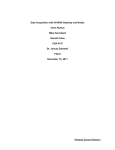
II. Principle of Operation
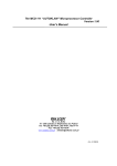
Description of the control panel in a sample configuration
COLLECTOR
TEMPERATURE
COLLECTOR
PUMP
HEAT
STORAGE
TIME
OPERATION
MODE,
OPTIONAL
DEVICE
ACTIVATED
TANK 2
TEMPERATURE
TEMPERATURE
STANDBY
MODE
EXIT
ENCODER
The device is controlled with an encoder. By
knob, you can enter a menu or confirm settings.
you can navigate in menu functions. To go to the
menu level), use the Exit button. All settings are
manner.
pressing the encoder
By turning the knob,
main page (or higher
changed in the same
-5-
ST – 402 USER'S MANUAL
III. User’s Menu
III.a) Main Page
During normal operation, the graphic display shows the Main Page that
contains,
apart
from
the
selected
configuration,
the
following
information:
- operation mode (or type of alarm),
- current time,
- collector temperature,
- current heat storage temperature,
- temperatures of all additional sensors depending on configuration.
To the right of the screen, the following icons are displayed:
1. Icon of the active operation mode:
Automatic operation mode
Collector defrosting mode
Holiday mode
Collector overheating (alarm mode)
Sensor failure (alarm mode)
2. Icon of the active optional device (peripherals):
Circulation pump
PLT (pellet) boiler fire-up
Heater
-6-
When one of the sensors is damaged, an additional icon
tech
starts
to flash in the area where the temperature of the damaged sensor is
normally displayed, to indicate which sensor has been disconnected or
damaged.
In addition to the above, a pump icon (revolves if in operation)
or/and valve icon (with an indication of the current circulation route) is
displayed on the system configuration diagram.
III.b) Operation Mode
With this function, you can select an operation mode.
1. Automatic mode.
In the automatic mode, the pump is running if the minimum
temperature difference between the collector and the tank is reached
(the temperature difference at which the pump is started is defined by
the "Solar Pump Delta" function in: SERVICE MENU > Accumulation
Tank > Solar Pump Delta). The pump continues to run until the setpoint
temperature is reached (the setpoint temperature is set with: SERVICE
MENU > Accumulation Tank > Setpoint Temperature) or
until the
collector temperature and the tank temperature equalize (in which case
the pump is restarted when the temperature at the collector rises above
the tank temperature by the value of solar pump delta). Once the pump
is shut off after the setpoint temperature has been reached, it will be
restarted if the temperature drops below the setpoint value by the value
of tank hysteresis (the hysteresis value is set with: SERVICE MENU >
Accumulation Tank > Storage Hysteresis).
2. Collector Defrosting.
With this function, you can manually start the collector pump
in order to melt snow built up on the solar panels. The mode remains
active for a period defined by the user. Then the controller returns to
-7-
ST – 402 USER'S MANUAL
the automatic mode (the defrosting time is set with: SERVICE MENU >
Solar Collector > Defrosting Time). The function can be deactivated
manually by selecting another operation mode.
3. Holiday Mode.
When the holiday mode is enabled, during daytime hours (from 6 00
a.m. until 1000 p.m.), the pump runs as in the automatic mode, whereas
during night hours (from 1000 p.m. until 600 a.m.), the pump is started
only if the collector temperature is lower than the tank temperature so
that the tank can be cooled.
ATTENTION >You can change the daytime cycle and night cycle
activation hour using the "DAY FROM" and "NIGHT FROM" settings.<
4. Manual Mode.
In this function, the user can enable or disable (by pressing the
encoder knob) the following:
- solar pump,
- second solar pump or switching valve,
- optional device (voltage-free signal, e.g. for firing up of a
pellet
boiler).
III.c) Clock
With this function, you can set the current time according to which
the controller is to operate.
III.d) Day From
With this setting, you can define at what time the daytime mode is
to be activated (Day From Hour).
III.d) Night From
With this setting, you can define at what time the night mode is to
be activated (Night From Hour).
-8-
tech
III.d) Language Version
You can select the language version for the controller.
III.e) Information
When this option is selected, the logo of the manufacturer is
displayed together with the software version.
IV. Service Menu
To enter the service settings, select SERVICE MENU, then input 112 with
the encoder and confirm the entry by pressing the knob. To return to the main
page (exit the service menu), press EXIT twice or wait approx. 30 seconds (for the
device to leave the service mode automatically).
IV.a) Accumulation Tank
With this menu, you can set all parameters associated with the
tank (heat storage).
IV.a.1) Setpoint Temperature
This function is used to define the setpoint temperature at the
storage that, if reached, will cause the collector pump to shut off.
IV.a.2) Maximum Temperature
With this option, you should define the highest permissible
temperature value for the tank to reach in case the collector is
overheated.
Should the collector reach the alarm temperature (overheating),
the pump will be started automatically in order to cool the collector,
regardless of the setpoint temperature. The pump continues to run until
the maximum storage temperature is reached or until the collector
temperature drops by the value of alarm hysteresis (see: SERVICE
MENU > Solar Collector > Alarm Hysteresis).
-9-
ST – 402 USER'S MANUAL
IV.a.3) Storage Hysteresis
With this function, you can define the value of storage hysteresis.
If the storage temperature reaches the setpoint value and the pump is
shut off, the pump will be restarted after the storage temperature drops
below the hysteresis value.
IV.a.4) Solar Pump Delta
This function is used to define the temperature difference between
the collector and the tank at which the pump starts to run (pump
activation threshold value).
IV.b) Solar Collector
With this menu, you can set all parameters associated with the
solar collector.
IV.b.1) Maximum temperature
With this setting, you can define the maximum safe temperature of
the collector. The value must be set according to technical data of the
collector in use.
Should the maximum (alarm) temperature be reached, the
controller will enter the collector overheating mode.
IV.b.2) Alarm Hysteresis
With this function, you can define the value of the collector alarm
hysteresis. If the storage temperature reaches the alarm value
(collector overheating) and the pump is started, the pump will be
stopped
again
after
the
collector
temperature
drops
below
the
maximum temperature by the hysteresis value.
IV.b.3) Defrosting Time
With this function you can define how long the pump is to run after
the boiler defrosting function is activated.
- 10 -
tech
IV.c) Peripherals
It is possible to connect and configure optional devices. If no
optional device is connected, select N/A (disable). Below described are
three available optional devices and their connections with all available
system configurations.
IV.c.1) Circulation Pump
Once the device is selected, set the periodical duty time and pause
time for the pump during its activity hours. Then define periods in which
the pump will be active using the "From Hour" and "Until Hour"
functions. If the same time is entered ("from – until"), the device will
run non-stop.
IV.c.2) PLT (Pellet) Boiler Fire-Up
With this option, you can set a voltage-free signal intended to fire
up the pellet boiler. Set the activation delta, i.e. the difference between
the setpoint temperature and actual temperature of the storage that, if
reached, will cause the controller to send a signal to fire up the boiler.
Then define a period in which the function will be active (using the
"From Hour" and "Until Hour" functions.
- 11 -
ST – 402 USER'S MANUAL
IV.c.3) Heater
The heater is used to electrically heat the tank. The principle
behind its operation is similar to one described in the previous case,
although the heater is to be connected with an additional contactor. Set
the activation delta (the difference between the setpoint temperature
and actual temperature of the storage) below which the controller will
start the heater. Then define a period in which the heating function will
be active (using the "From Hour" and "Until Hour" functions.
- 12 -
tech
IV.d) Installation Diagram
For the solar system to work properly, it is essential to determine
the right installation diagram (SERVICE MENU > INSTALLATION
DIAGRAM) and to properly adjust the selected configuration (SERVICE
MENU > INSTALLATION OPTIONS).
ATTENTION When selecting the installation diagram, the numbers of
sensors are displayed in place of their temperature values. Sensors
must be connected in the following order (starting from the left):
(1) – collector sensor,
(2) – storage sensor,
(3) – additional sensor 1,
(4) – additional sensor 2.
- 13 -
ST – 402 USER'S MANUAL
IV.d.1) 1/9 Diagram
The 1/9 diagram includes:
➔
collector pump,
➔
accumulation tank,
➔
a single arrangement of collectors,
➔
additional peripherals.
System sensors:
➔
collector sensor,
➔
accumulation tank sensor.
IV.d.2) 2/9 Diagram
The 2/9 diagram includes:
➔
collector pump,
➔
switching valve,
➔
accumulation tank,
➔
a single arrangement of collectors,
➔
additional peripherals.
System sensors:
➔
collector sensor,
➔
two accumulation tank sensors.
Additional installation options:
➔
valve hysteresis
The tank is initially heated in its upper portion (from where hot
consumption water is supplied), and when it has sufficiently been
heated, the valve switches to the circuit of the other portion. The valve
will switch back when the priority portion of the tank cools down by the
value of valve hysteresis (i.e. the temperature difference between the
two portions of the tank).
- 14 -
tech
IV.d.3) 3/9 Diagram
The 3/9 diagram includes:
➔
two
collector
independently,
pumps
each
(running
according
to
its
circuit),
➔
accumulation tank,
➔
two arrangements of collectors,
➔
additional peripherals.
System sensors:
Attention.
Solar
➔
two collector sensors,
➔
accumulation tank sensor.
collector
settings
(SERVICE
MENU
>
SOLAR
COLLECTOR) refer equally to collectors positioned in both directions.
IV.d.4) 4/9 Diagram
The 4/9 diagram includes:
➔
collector pump,
➔
switching valve,
➔
accumulation tank,
➔
two arrangements of collectors,
➔
additional peripherals.
System sensors:
➔
➔
two collector sensors,
accumulation tank sensor.
Additional installation options:
➔
collector delta
In this configuration, only one heating circuit is active. The
switching valve is intended to switch the circuit to a collector the
- 15 -
ST – 402 USER'S MANUAL
temperature of which is currently higher at least by the value of
collector delta (the temperature difference between the two collectors).
IV.d.5) 5/9 Diagram
The 5/9 diagram includes:
➔
collector pump,
➔
auxiliary pump (pump 2),
➔
accumulation tank,
➔
a single arrangement of collectors,
➔
additional peripherals.
System sensors:
➔
collector sensor,
➔
two accumulation tank KTY sensors,
➔
boiler temperature sensor.
Additional installation options:
➔
activation delta
This configuration features an additional heating circuit to provide
additional heating with the use of a central heating boiler. If the tank
temperature is lower than the tank setpoint temperature at least by the
setpoint value of activation delta (i.e. the difference between the
setpoint temperature and the actual temperature of the tank), the
auxiliary pump (from the boiler) is started in order to provide additional
heating for the accumulation tank (providing that the boiler temperature
is higher than the tank temperature). This setting is available only in
periods defined by the user ("from, until").
➔
From Hour
➔
Until Hour
These settings are used to define periods ("from, until") in which
the central heating boiler will provide additional heating for the
accumulation tank.
- 16 -
tech
IV.d.6) 6/9 Diagram
The 6/9 diagram includes:
➔
collector pump,
➔
switching valve,
➔
two accumulation tanks,
➔
a single arrangement of collectors,
➔
additional peripherals.
System sensors:
➔
collector sensor,
➔
accumulation tank sensors.
Additional installation options:
➔
tank 2 setpoint temperature
If the setpoint temperature for the first tank is reached, the valve
will switch the supply to the second tank. With this function, you can set
the setpoint temperature for the second tank.
➔
tank 2 hysteresis
Once the setpoint temperature is reached, the pump is shut off.
The pump will start again when the tank temperature drops below the
setpoint value by the tank 2 hysteresis.
➔
valve hysteresis
This setting is used to adjust the valve when cooling the collector in
the summer mode or alarm mode as well as during defrosting. The
valve hysteresis defines the temperature difference between the tanks
at which the valve is switched to the other tank.
➔
tank 2 maximum temperature
With this option, you should define the highest permissible
temperature value for the second tank to reach in case the collector is
overheated.
- 17 -
ST – 402 USER'S MANUAL
IV.d.7) 7/9 Diagram
The 7/9 diagram includes:
➔
two collector pumps,
➔
two accumulation tanks,
➔
a single arrangement of collectors,
➔
additional peripherals.
System sensors:
➔
collector sensor,
➔
accumulation tank sensors.
Additional installation options:
➔
tank 2 setpoint temperature
This function is used to define the setpoint temperature of the
second tank that, if reached, will cause the collector pump 2 to stop.
➔
tank 2 hysteresis
Once the setpoint temperature is reached, the pump is shut off.
The pump will start again when the tank temperature drops below the
setpoint value by the tank 2 hysteresis.
➔
tank 2 maximum temperature
With this option, you should define the highest permissible
temperature value for the second tank to reach in case the collector is
overheated.
➔
pump 2 delta
This function is used to define the temperature difference between
the collector and the second tank at which pump 2 starts to run (pump
activation threshold value).
➔
operation algorithm
With this option, you can select operation modes for the pumps.
The pumps can be operated in the following modes:
a) tank 1 priority – initially, tank 1 is heated (only pump 1 is
- 18 -
tech
running), and when the setpoint temperature is reached, pump 2 is
activated to provide additional heating for tank 2.
b) parallel operation – the pumps are running independently, each
in its own range (according to its settings), with both tanks being
heated simultaneously.
IV.d.8) 8/9 Diagram
The 8/9 diagram includes:
➔
collector pump,
➔
tank 2 pump,
➔
two accumulation tanks,
➔
a single arrangement of collectors,
➔
additional peripherals.
System sensors:
➔
collector sensor,
➔
two sensors of the main accumulation tank,
➔
sensor of the additional accumulation tank.
Additional installation options:
➔
tank 2 setpoint temperature
This function is used to set the setpoint temperature of the second
tank that, if reached, will cause the pump of tank 2 (collector pump 2) to
stop.
➔
tank 2 hysteresis
Once the setpoint temperature is reached, pump 2 is shut off.
Pump 2 will start again when the tank temperature drops below the
setpoint value by the tank 2 hysteresis.
➔
pump 2 delta
This function is used to define the temperature difference between
tank 1 and 2 at which pump 2 is activated (pump 2 activation threshold
- 19 -
ST – 402 USER'S MANUAL
value).
➔
tank 2 maximum temperature
With this option, you should define the highest permissible
temperature value for the second tank to reach in case the collector is
overheated.
➔
operation algorithm
With this option, you can select operation modes for the pumps.
The pumps can be operated in the following modes:
a) tank 1 priority – initially, tank 1 is heated (only pump 1 is
running), and when the setpoint temperature is reached, pump 2 is
activated to provide additional heating for the other tank. Pump 2 is
shut off when the setpoint temperature for the second tank is reached
or when temperatures of both tanks equalize.
b) parallel operation – the pumps are running independently, each
in its own range (according to its settings), with both tanks being
heated simultaneously (in parallel).
IV.d.9) 9/9 Diagram
The 9/9 diagram includes:
System sensors:
➔
collector sensor,
➔
accumulation tank sensor.
➔
heat exchanger sensor.
- 20 -
➔
collector pump,
➔
switching valve,
➔
accumulation tank,
➔
heat exchanger (heat receiver),
➔
a single arrangement of collectors,
➔
additional peripherals.
tech
Apart from the accumulation tank, the system features a
heat
receiver (e.g. a swimming pool or central heating system) intended to
emit heat instead of accumulating it.
Additional installation options:
➔
tank 2 setpoint temperature
This function is used to define the setpoint temperature at the
second heat receiver (exchanger) that, if reached, will cause the
collector pump to stop.
➔
tank 2 hysteresis
Once the setpoint temperature at the receiver is reached, the pump
is shut off. The pump will be restarted when the temperature of the heat
receiver drops below the setpoint value by the value of tank 2
hysteresis (providing that tank 1 is well heated and the valve has not
been switched to the accumulation tank).
➔
valve hysteresis
If the setpoint temperature for the first tank is reached, the valve
will supply the heat receiver. The valve will switch back when the first
tank cools down by the value of valve hysteresis (i.e. the temperature
difference between the two tanks).
➔
tank 2 maximum temperature
With this option, you should define the highest permissible
temperature value for the second tank (heat receiver) to reach in case
the collector is overheated.
- 21 -
ST – 402 USER'S MANUAL
V. Standby Mode
When the Standby Mode button is pressed on the control panel, all
actuators within the system are disabled. The button is used when the
controller needs to be temporarily stopped.
VI. Protections
In order to ensure a safe and faultless operation, the regulator has
been provided with numerous protections.
1. System sensor protections.
When one of the sensors is damaged, an acoustic warning is sounded,
and to the right of the display, the following icon is shown:
additional icon
An
starts to flash in the area where the temperature of
the damaged sensor is normally displayed, to indicate which sensor has
been disconnected or damaged.
In order to deactivate the alarm in the sensor failure mode, press the
EXIT button.
2. Collector overheating protection.
Should the maximum (alarm) temperature be reached, the controller
will enter the collector overheating mode, and in the display, the
following icon is shown:
. The pump starts to run in order to cool
the collector until the maximum storage temperature is reached or until
the collector temperature drops by the value of alarm hysteresis (see:
SERVICE MENU > Solar Collector > Alarm Hysteresis). In case two tanks
are available, both tanks are used to cool the overheated collector
(simultaneously or consecutively, depending on the set operation
algorithm).
3. Heat Storage Protection.
If the boiler is overheated, each tank can be heated up to the set safe
- 22 -
tech
temperaturethreshold. Once this temperature is reached, the pump of
the given tank is stopped (in the configuration of two tanks with a valve,
the circuit of the second tank is enabled).
3. Fuse.
The regulator has a network protection WT 3.15A tube fuse.
ATTENTION: it is not advisable to use fuses with higher current
ratings. Higher current ratings may cause damage to the controller.
VII. Maintenance
Before and during the heating season, the ST-402 controller should be
checked for condition of its cables. You should also check if the
controller is properly mounted and clean it if dusty or dirty.
ST-402 Technical Specifications
Supply voltage
230V/50Hz +/- 10%
Temperature adjustment range
8oC : 90oC
Power consumption
max. 4W
Collector sensor temperature resistance
-30oC : 180oC (momentarily 200oC)
Temperature resistance of the remaining sensors
-25oC : 100oC
Measurement accuracy
1oC
Ambient temperature
10oC : 50oC
Load on each output
1A
Fuse insert
3.15A
We are committed to protecting the environment. Manufacturing electronic devices imposes
an obligation of providing for environmentally safe disposal of used electronic components
and devices. Hence, we have been entered into a register kept by the Inspection For
Environmental Protection. The crossed out bin symbol on a product means that the product
may not be disposed of to household waste containers. Recycling of wastes helps to protect
the environment. The user is obliged to transfer their used equipment to a collection point
where all electric and electronic components will be recycled.
- 23 -
ST – 402 USER'S MANUAL
VIII. Assembly
ATTENTION: all assembly works must only be carried out by qualified persons.
During assembly, the device must be disconnected (make sure the power cord is
unplugged)!
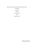
Wire connections
Collector Installation Block Diagram
- 24 -
tech
Table of Contents
I. Intended Use.......................................................................5
II. Principle of Operation..........................................................5
III. User’s Menu...................................................................... 6
III. a) Main Page..................................................................6
III. b) Operation Mode..........................................................7
III. c) Clock......................................................................... 8
III. d) Day From...................................................................8
III. e) Night From.................................................................8
III. f) Language Version........................................................9
III. g) Information................................................................9
IV. Service Menu.....................................................................9
IV. a) Accumulation Tank......................................................9
IV. a.1) Setpoint Temperature...........................................................9
IV. a.2) Maximum Temperature.........................................................9
IV. a.3) Tank Hysteresis..................................................................10
IV. a.3) Solar Pump Delta................................................................10
IV. b) Solar Collector...........................................................10
IV. b.1) Maximum Temperature ......................................................10
IV. b.2) Alarm Hysteresis................................................................10
IV. b.3) Defrosting Time..................................................................11
IV. c) Peripherals................................................................11
IV. c.1) Circulation Pump ...............................................................11
IV. c.2) PLT (Pellet) Boiler Fire-Up....................................................12
IV. c.3) Heater...............................................................................12
IV. d) Installation Diagram...................................................13
IV. d.1) 1/9 Diagram......................................................................13
IV. d.2) 2/9 Diagram......................................................................14
IV. d.3) 3/9 Diagram......................................................................14
IV. d.4) 4/9 Diagram......................................................................15
- 25 -
ST – 402 USER'S MANUAL
IV. d.5) 5/9 Diagram......................................................................15
IV. d.6) 6/9 Diagram......................................................................16
IV. d.7) 7/9 Diagram......................................................................18
IV. d.8) 8/9 Diagram......................................................................19
IV. d.9) 9/9 Diagram......................................................................21
V. Standby Mode...................................................................22
VI. Protections...................................................................... 22
VII. Maintenance...................................................................24
VIII. Assembly...................................................................... 25
- 26 -
tech
- 27 -
ST – 402 USER'S MANUAL
- 28 -