1
FUEL/AIR DATA COMPUTER
(ADC 2000)
P/NS:
962830A-1(A)
962830A-2(A)
962830A-3(A)
INSTALLATION MANUAL
REV J
Shadin Avionics
6831 Oxford Street
St. Louis Park, MN 55426
USA
Sales: (800) 328-0584
Customer Service: (800) 388-2849
www.shadin.com
P/N: IM2830A
IM2830AJ.doc
IM2830A
Directory: 962830A
Rev: J
Shadin Avionics
INSTALLATION MANUAL
FUEL/AIR DATA COMPUTER
Sec: VII
P/N 962830A-1(A), 962830A-2(A), 962830A-3(A)
Page i of vi
PAGE CONTROL CHART
SECTION
NO.
1.0
2.0
DESCRIPTION
PAGE
REVISION LOG
vi
OVERVIEW
1-1
1.1
1.2
1.3
1.4
1.5
1-1
1-1
1-2
1-3
1-3
The Manual
Product Information
System Configuration
Fuel Totalizer Configuration
F/ADC2000, Argus Moving Map Configuration
FUEL AND AIR DATA SYSTEM SPECIFICATIONS
2-1
2.1
2.2
2-1
2-1
2-2
2-2
2-3
2-4
2-5
2-5
2-5
2-5
2-6
2-6
2-7
2-8
2-8
2-8
2-8
2-9
2-10
2-11
2-12
2-13
2-14
2-14
2-14
2-14
2-15
2-15
2-15
2-16
2-16
2.3
2.4
2.5
2.6
2.7
2.8
2.9
Input Data Range
Output Data Range
Table 1 – Calibrated Airspeed Tolerance
Table 2 – Pressure Altitude Tolerance
Table 3 – Vertical Airspeed Tolerance
Table 4 – MACH Tolerance
Dimensions
Power Requirements
Output Data
2.5.1 Serial Output Data Parameters
2.5.2 ARINC 429 Labels Associated with Switch Settings
Table 5 – ARINC Label Configuration
2.5.3 ARINC 429 Labels Associated with Switch Settings
Limitations
2.6.1 Warm-up Time
2.6.2 Supplemental Equipment
2.6.3 Static/Pitot Source Error Correction (SSEC/PSEC)
2.6.4 SSEC/PSEC Listing
2.6.4 SSEC/PSEC Listing (Continued)
2.6.4 SSEC/PSEC Listing (Continued)
2.6.4 SSEC/PSEC Listing (Continued)
Part Numbering Scheme
Electrical Interface Specifications
2.8.1 Heading Interface
2.8.2 Fuel Flow Interfaces
2.8.2.1 Digital Fuel Flow
2.8.2.2 Sine Wave Fuel Flow
2.8.2.3 DC Voltage Fuel Flow
2.8.3 Baro Interface
Statistical Specifications
2.9.1 Mean Time Between Failures
IM2830AJ.doc
IM2830A
Directory: 962830A
Rev: J
Shadin Avionics
INSTALLATION MANUAL
FUEL/AIR DATA COMPUTER
Sec: VII
P/N 962830A-1(A), 962830A-2(A), 962830A-3(A)
Page ii of vi
PAGE CONTROL CHART
SECTION
NO.
3.0
DESCRIPTION
PAGE
CERTIFICATION
3-1
Supplemental Type Certificate
3-2
4.0
PLACING AN ORDER
4-1
5.0
INSTALLATION PROCEDURE
5-1
5.1
5.2
5.3
5.4
5.5
5.6
5.7
5.8
5.9
5.10
5-1
5-1
5-1
5-2
5-3
5-4
5-5
5-6
5-6
5-6
General
F/ADC Location Selection
Mounting the F/ADC
Mounting the OAT Probe
Connection to the Fuel Flow Sensor
Connection to the Heading Source
Connection to the Pitot and Static Lines
Connection to the Navigation Management System
Connection to the Altimeter Baro Pot
Post Installation Checkout
6.0
OPERATING INSTRUCTIONS
6-1
7.0
INITIALIZATION
7-1
8.0
MAJOR COMPONENTS OF THE SYSTEM
8-1
IM2830AJ.doc
IM2830A
Directory: 962830A
Rev: J
Shadin Avionics
INSTALLATION MANUAL
FUEL/AIR DATA COMPUTER
Sec: VII
P/N 962830A-1(A), 962830A-2(A), 962830A-3(A)
Page iii of vi
PAGE CONTROL CHART
SECTION
NO.
9.0
10.0
DESCRIPTION
PAGE
CONFIGURING THE AIR DATA
9-1
9.1
9.2
9-1
9-2
9-3
9-3
9-4
9-5
9-6
9-6
9-7
9-8
9-9
9-10
9-11
9-11
9-12
9-13
9-14
9-15
9-16
9-16
9-17
9-18
9-19
9-20
9-21
9-22
9-22
Configuring with ‘ADSETUP User Manual’
Configuring Manually
Loop-back Procedure 1 for S/W Version 93.00.16 - 93.00.29
Stage 0 Loop-back Configuration
Stage 1 Loop-back Configuration
Stage 1 Loop-back Configuration
Loop-back Procedure 2 for S/W Version 93.00.51 – 93.00.71
Stage 0 Loop-back Configuration
Stage 1 Loop-back Configuration
Stage 1 Loop-back Configuration
Stage 2 Loop-back Configuration
Stage 3 Loop-back Configuration
Loop-back Procedure 3 for S/W Version 93.00.77
Stage 0 Loop-back Configuration
Stage 1 Loop-back Configuration
Stage 1 Loop-back Configuration
Stage 2 Loop-back Configuration
Stage 3 Loop-back Configuration
Loop-back Procedure 4 for S/W Version 93.00.82 +
Stage 0 Loop-back Configuration
Stage 1 Loop-back Configuration
Stage 1 Loop-back Configuration
Stage 2 Loop-back Configuration
Stage 3 Loop-back Configuration
Stage 4 Loop-back Configuration
Select No Delay
Special Options
SETTING THE K-FACTOR
Table 6 - Analog K-Factor Settings
Table 7 - Digital K-Factor Settings Table 2 (Matrix 0)
Table 7 - Digital K-Factor Settings Table 2 (Matrix 0)
Table 7 - Digital K-Factor Settings Table 2 (Matrix 0)
Table 8 - Alternate Digital-K-Factor Setting Table 3 (Matrix 1)
10-1
10-2
10-3
10-4
10-5
10-6
IM2830AJ.doc
Rev: J
11.0
IM2830A
Directory: 962830A
Shadin Avionics
INSTALLATION MANUAL
FUEL/AIR DATA COMPUTER
Sec: VII
P/N 962830A-1(A), 962830A-2(A), 962830A-3(A)
Page iv of vi
INSTALLATION DRAWINGS AND INSTALL KITS PARTS LISTS
Drawing No.
Description/Part Number
DATE
REV
4028-005
Installation, OAT Probe Assembly Kit
P/N 681201-1
02/14/05
C
N/A
Parts List, OAT Probe Assembly Kit
P/N 681201-1
04/06/07
H
4028-395
Installation, Mounting Tray, ADC 2000
08/01/05
C
4028-617
Installation, ADC2000, Digital FF, MS Conn.
P/N 962830A-1
04/12/05
D
4028-618
Installation, ADC2000, Sinewave FF, MS Conn.
P/N 962830A-2
04/12/05
E
4028-619
Installation, ADC2000, DC FF, MS Conn.
P/N 962830A-3
04/12/05
E
4028-A45
Installation Wiring, ADC 2000 to
COMM/PWR/BARO/OAT/HEADING
09/12/00
B
4028-A46
Installation Wiring, ADC 2000 MS Conn, Digital, Sine
and DC Fuel Flow
03/11/03
B
4028-A47
Installation Wiring, ADC2000, MS Conn
to Altimeter Baro Pot
03/11/03
D
4028-A62
Installation Wiring, Loop-back Harness
for F/ADC 200, 2000, MS Connector
09/28/98
–
4028-A80
Label, ADC 200/2000 Access Cover
P/N 712801
02/14/05
A
4070-005
Installation, Serial to Argus 5000/7000 Converter
P/N 937000-03
02/14/05
B
N/A
Parts List, Install Kit, ADC 2000, MS Conn, No OAT
P/N IK9630A-1
04/09/07
H
IM2830AJ.doc
Rev: J
11.0
IM2830A
Directory: 962830A
Shadin Avionics
INSTALLATION MANUAL
FUEL/AIR DATA COMPUTER
Sec: VII
P/N 962830A-1(A), 962830A-2(A), 962830A-3(A)
Page v of vi
INSTALLATION DRAWINGS AND INSTALL KITS PARTS LISTS (cont.)
AIRCRAFT SPECIFIC
4028-A29
Installation Wiring, F/ADC200, 2000 or Digidata with DC
FF Piper Cheyenne PA31T
01/17/05
C
4028-A48
Installation Wiring F/ADC 2000 w/ Analog FF to Beech
King Air Indicators MS Connector
03/11/03
B
4028-A49
Installation Wiring, F/ADC 2000 MS Connector, Sine FF
to Mitsubishi MU-300 and Model 400 Beechjet
01/20/99
A
4028-A50
Installation Wiring, F/ADC 2000 to Mitsubishi
MS Conn Sine FF, to MU-2 w/Foxboro PC-620 System
07/19/00
B
4028-A51
Installation Wiring, F/ADC 2000 MS Conn, with DC FF to
Cessna Citation 500, 501, 550, S550, 551, 552
01/20/99
B
4028-A52
Installation Wiring, F/ADC 2000 MS Conn with DC FF to
Cessna Citation 525 Jet
01/20/99
B
4028-A53
Installation Wiring, F/ADC 2000 MS Conn with Digital FF
to Bombardier LearJet 24, 25D
01/20/99
B
4028-A54
Installation Wiring, F/ADC 2000 MS Conn with Sine FF to
Rockwell Commander 690 and 695
01/20/99
B
4028-A55
Installation Wiring, F/ADC 2000 MS Conn with DC FF to
Raytheon BeechJet 400A Aircraft
01/20/99
B
4028-A56
Installation Wiring, F/ADC 2000 MS Conn with DC FF to
Westwind 1124 Models
01/20/99
B
4028-A57
Installation Wiring, F/ADC 2000 MS Conn to Fairchild
SA226 Series Aircraft
03/29/05
C
4028-A58
Installation Wiring, F/ADC 2000 MS Conn to Aerospatiale
AS365N2 Dauphin
01/20/99
B
4028-A59
Installation Wiring, F/ADC 2000 MS Conn to
Aerospatiale AS332 Super Puma
01/20/99
B
4028-A60
Installation Wiring, F/ADC 2000 MS Conn Shadin FF
Indicators to Bendix/King Nav. Receiver
03/11/03
B
4028-A61
Installation Wiring F/ADC 2000 MS Conn and Shadin
Converter to Eventide Argus
09/18/00
B
4028-B98
Installation Wiring F/ADC 2000, MS Conn Shadin Fuel
Flow Indicators to Garmin 430/530
04/29/11
D
IM2830AJ.doc
IM2830A
Directory: 962830A
Rev: J
Shadin Avionics
INSTALLATION MANUAL
FUEL/AIR DATA COMPUTER
Sec: VII
P/N 962830A-1(A), 962830A-2(A), 962830A-3(A)
Page vi of vi
REVISION LOG
REV
DATE
APP’D
–
12-08-98
KCL
A
06-17-99
KCL
B
09-18-00
EDJ
C
11-01-00
KCL
D
06-27-02
EDJ
E
04-12-05
ZK
F
09-19-05
CB
G
12-08-05
04/24/08
CB
EDJ
07/18/11
ZK
H
J
CHANGE
Baseline release
Update pages 2-1, 2-7 – 2-10, 5-5, 9-9, header and grammar, changed Dwg
revisions as indicated.
Moved page 9-11 to 9-16. Added pages 9-11 to 9-15. Corrected page 9-4 and 97 for Bendix letter description. Updated OAT probe kit P/N’s. Changed page iv
for Dwg # 4028-A45 to include Garmin 430/530. Page vi changed to include
Dwg # 4028-B98. Changed page 2-1 to adjust OAT tolerance. Changed page 23 to add labels 234 and 235. Change 2-4 and 2-5 to include Mk VI and VIII
EGPWS models. Changed page 5-4 to add Sandel heading source. Page 5-1
changed by inclusion of TSO compliance paragraph. Inserted page 3-2 STC.
Added sections 2.8 and 2.9. Updated sections 1.4, 2.0, 5.1, 5.7 and 9.2. Moved
section 9.0 to page iii. Moved page 9-16 to 9-21. Updated Dwg # 4028-A47.
Updated section 1.3 system figure. Added P/N 681201 OAT probe installation
and parts list to page iv drawing list. Updated Page 2-4 ARINC Table. Corrected
page 10-3 Table 2. Added pages 9-21 to 9-26. Page 9-21 became 9-27.
Removed P/N 681201A-1 OAT Probe Assembly Kit, Loop-back procedure SW
Version 93.00.79. Updated pages 2-1, 2-12, 5-2, section 9 and section 11.
Changed company name.
Updated install kit IK9630A-1, Dwg # 4028-395. Updated Section 1.3 system
figure and sections 5.1and 5.2. Fixed typo in section 2.6.2.
Updated Company logo and install kit IK9630A-1
Updated all sections with P/N 962830A-1(A), -2(A), & -3(A), updated Section
2.2, 2.5.2, 2.5.3, 2.7, 3.0, 5.1, and 9.0. Added Antonov and Yak-40 SSEC
information in Section 2.6.4.
Updated 4028-B98 Rev D and 681201-1 Rev H parts list. Fixed tabs on page 11 so that it doesn’t get corrupted when creating a pdf. Replaced missing Table 4
– MACH Tolerance and updated all of section 2 to compensate for the added
page. Corrected the Table numbers and descriptions in section 9. Updated the
table of contents to reflect all the changes.
The information in this manual is subject to change without notification. To ensure complete and current updates, note the
Revision Log above and call Technical Assistance for updated information.
IM2830AJ.DOC
IM2830A
Directory: 962830A
Shadin Avionics
INSTALLATION MANUAL
FUEL/AIR DATA COMPUTER
P/N 962830A-1(A), 962830A-2(A), 962830A-3(A)
Rev: J
1.0
OVERVIEW
1.1
The Manual
Page: 1-1
This manual is designed to facilitate the installation of the Shadin Fuel/Air Data Computer
(ADC 2000).
1.2
Product Information
The Shadin ADC 2000 system is designed to provide a combined source of fuel and Air Data.
Listed below are the navigational systems that the ADC 2000 has been designed to be
compatible with.
Receives Serial Data from:
Magellan
Skynav 5000
ARNAV
STAR 5000
FMS 7000
R5000
Trimble
2000/2000A
2100/3000
Bendix King
KLN90
KLN90A
3100/2101 KLN90B
KLN89/89B
KLN900
Garmin
150, 155, 155XL, 165
230, 230XL
300, 300XL
430, 530
BFGoodrich
Pronav LNS 6000
IIMorrow
611, 612, 618
NMS 2001
800, 820, 360
GX50, 55, 60
Transmits Serial Data to:
ARNAV
Magellan
Bendix/King
Trimble
Garmin
Note: To find out which particular receiver
models have AIR DATA receive capability,
contact the manufacturers.
Transmits ARINC Data to:
ASINC
Bendix King
Airshow
EFIS 40/50
Honeywell
SPZ-5000
Global
GNSX
GNS-Xls
Trimble
TNL8100
IIMorrow
2101
Universal
UNS-1M
Data Nav III
IM2830AJ.DOC
IM2830A
Directory: 962830A
Shadin Avionics
INSTALLATION MANUAL
FUEL/AIR DATA COMPUTER
P/N 962830A-1(A), 962830A-2(A), 962830A-3(A)
Rev: J
1.3
Page: 1-2
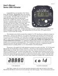
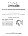
System Configuration
The Fuel/Air Data system is a remote mounted computer, which is connected to the GPS
receiver via serial data. It is also connected to the pitot and static line, OAT probe, fuel flow
sensors, altimeter barometric pressure potentiometers and the aircraft heading source.
PITOT
STATIC
NAV
RECEIVER
OAT
MAG. HEADING
L. ENGINE F/F
FUEL/AIR DATA
COMPUTER
with
MS Connector
R. ENGINE F/F
BARO POT
(Optional)
SYSTEM CONFIGURATION
STANDARD
ARINC 429
OUTPUT TO
EFIS/FLIGHT
MANAGEMENT
SYSTEM
IM2830AJ.DOC
IM2830A
Directory: 962830A
Shadin Avionics
INSTALLATION MANUAL
FUEL/AIR DATA COMPUTER
P/N 962830A-1(A), 962830A-2(A), 962830A-3(A)
Rev: J
1.4
Page: 1-3
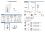
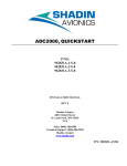
Fuel Totalizer Configuration
Shown below is an optional system configuration utilizing a Shadin Fuel Flow Indicator. Note
that the only navigational receivers supported in this configuration are the Bendix/King KLN
series and the Garmin 430/530. Consult Drawing Number 4028-A60 contained in this manual
for installation information on the Bendix/King KLN series. Consult Drawing Number 4028B98 for installation information on the Garmin 430/530.
Garmin
Bendix/King
430,
530
KLN90, A, B
KLN89
KLN900
Shadin
DigiFlo
MiniFlo
MicroFlo
RS-232
L.Fuel Flow Transmitter
R. Fuel Flow Transmitter
or
Shadin
RS-232
1.5
F/ADC200
F/ADC2000
RS-232
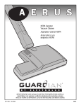
F/ADC2000, Argus Moving Map Configuration
Shown below is the system configuration that supports output to an Eventide Argus moving
map using the Shadin serial to serial data converter P/N 937000-03. The fuel and AIR DATA
are displayed on the Eventide-Argus moving map. Consult Drawing numbers 4070-005 and
4028-A61 contained in this manual.
Shadin
RS-232 or RS422
F/ADC2000
RS-232 or RS422
Shadin
Navigational
Receiver
RS-232
Converter
P/N 937000-03
Eventide
Argus
M oving M ap
P/N 5000
P/N 7000
IM2830AJ.DOC
IM2830A
Directory: 962830A
Shadin Avionics
INSTALLATION MANUAL
FUEL/AIR DATA COMPUTER
P/N 962830A-1(A), 962830A-2(A), 962830A-3(A)
Rev: J
2.0
FUEL AND AIR DATA SYSTEM SPECIFICATIONS
2.1
Input Data Range
Pitot
Static
OAT
Heading
Fuel Flow
K-Factor
2.2
20 to 350 kt.
-1000 to 55,000 ft.
-60°C to +60°C
0 - 360°
1 to 450 GPH Range Selected
500 to 130000 PPG Continuous
Output Data Range
PARAMETER
IAS
P.ALT
OAT
TRUE HEADING
MAGNETIC HEADING
IVS
TAS
MACH
WIND SPEED
WIND DIRECTION
FUEL FLOW
Accuracy*
Table 1
Table 2
±1.5°C per TSO
±2°
±1°
Table 3
Table 1
Table 4
±5 kts.
±10°
±2%
RANGE
20 to 350 kts.
–1000 to 50000 ft.
–60°C to +60°C
0 - 360 degrees
0 - 360 degrees
± 10,000 ft./min.
20 - 600 kts.
.2 - .95
5 - 360 kts.
0 - 360 degrees
1-450 GPH
* Listed accuracies are after warm-up is complete per the ambient temperatures listed in Section 2.6.1
Page: 2-1
IM2830AJ.DOC
IM2830A
Directory: 962830A
Shadin Avionics
INSTALLATION MANUAL
FUEL/AIR DATA COMPUTER
Rev: J
P/N 962830A-1(A), 962830A-2(A), 962830A-3(A)
Page: 2-2
This table is used as the tolerance for both IAS and TAS. For values between table rows,
linearly interpolate between the adjacent table points.
AIRSPEED
KNOTS
TOLERANCE
± KNOTS
50
80
100
120
150
200
250
300
350
400
450
5.0
3.0
2.0
2.0
2.0
2.0
2.4
2.8
3.2
3.6
4.0
Table 1 - Calibrated Airspeed Tolerance
This table is used as the tolerance for pressure altitude. Note that for an altitude between points
in the tables, the tolerance is linearly interpolated between the adjacent table points.
ALTITUDE
FEET
TOLERANCE
± FEET
0
1000
2000
3000
4000
5000
8000
11000
14000
17000
20000
30000
40000
50000
25
25
25
25
25
25
30
35
40
45
50
75
100
125
Table 2 -Pressure Altitude Tolerance
IM2830AJ.DOC
IM2830A
Directory: 962830A
Shadin Avionics
INSTALLATION MANUAL
FUEL/AIR DATA COMPUTER
Rev: J
P/N 962830A-1(A), 962830A-2(A), 962830A-3(A)
Page: 2-3
This table is used as the tolerance for vertical speed. For values between table rows, linearly
interpolate between the adjacent table points.
VERTICAL
SPEED
FPM
20000
6000
4000
2000
1000
500
200
100
50
0
-50
-100
-200
-500
-1000
-2000
-4000
-6000
-20000
TOLERANCE
± FPM
1000
300
200
100
50
45
45
45
45
45
45
45
45
45
50
100
200
300
1000
Table 3 - Vertical Airspeed Tolerance
IM2830AJ.DOC
IM2830A
Directory: 962830A
Shadin Avionics
INSTALLATION MANUAL
FUEL/AIR DATA COMPUTER
Rev: J
P/N 962830A-1(A), 962830A-2(A), 962830A-3(A)
Page: 2-4
This table is used as the tolerance for MACH Number. For values between table rows, linearly
interpolate between the adjacent table points.
ALTITUDE
TOLERANCE
FEET
MACH
± MACH
0
.3
.012
.4
.012
.5
.010
.6
.0075
.4
.012
.5
.010
.6
.0075
.7
.005
.4
.012
.5
.010
.6
.0075
.7
.005
.6
.0075
.7
.005
.80
.005
.90
.005
.95
.0075
.70
.005
.80
.005
.90
.005
.95
.0075
.75
.005
.90
.005
.95
.0075
1.00
.015
10,000
20,000
30,000
40,000
50,000
Table 4 - MACH Tolerance
IM2830AJ.DOC
IM2830A
Directory: 962830A
Shadin Avionics
INSTALLATION MANUAL
FUEL/AIR DATA COMPUTER
P/N 962830A-1(A), 962830A-2(A), 962830A-3(A)
Rev: J
2.3
Page: 2-5
Dimensions (including mounting rack)
Size: 7.5" L x 4.3" H x 3.9" W
Weight: 2.75 lb.
2.4
Power Requirements
System Power required: 28 VDC @ 1300 mA 14 VDC @ 900 mA
2.5
Output Data
1. Electric Format: RS-422 or RS-232
2. ARINC 429 low/high speed GAMA (Has to be configured at the factory)
See paragraph 2.5.3 for ARINC 429 output data capabilities.
2.5.1
Serial Output Data Parameters
Fuel Group
L. ENG. Fuel Flow
R. ENG. Fuel Flow
Fuel Used Total
Total Fuel Used
Fuel Used L. ENG.
Fuel Used R. ENG.
Fuel Remaining
NM/Fuel Unit (ground)
Fuel to Destination
Fuel at Destination
AIR DATA Group
Pressure Altitude
Rate of Turn
Density Altitude
MACH Number
Barometric Corrected Altitude Wind Direction and Speed
Indicated Air Speed
Baro Correction (mb #1)
True Air Speed
Baro Correction (hg”)
Vertical Speed
True Air Temperature
Outside Air Temperature
Drift Angle
Magnetic Heading
Note: Not all parameters will be available to all navigational receivers. Contact the manufacturer for display capabilities.
IM2830AJ.DOC
IM2830A
Directory: 962830A
Shadin Avionics
INSTALLATION MANUAL
FUEL/AIR DATA COMPUTER
P/N 962830A-1(A), 962830A-2(A), 962830A-3(A)
Rev: J
2.5.2
Page: 2-6
ARINC 429 Labels Associated with Switch Settings
In Table 5 – ARINC Label Configuration below, the heading row containing the numbers 1-A
indicates the setting of the ARINC rotary switch on the back of the unit. The number in the cell
at the intersection of an ARINC switch setting and an ARINC label number is the repeat time
in msec for that label. Zero indicates that the label is not generated with that switch setting.
Tolerance on the rate is ± 10% averaged over one second.
LABEL
074G
075G
100
113G
114
115
116
147G
203
204
205
206
210
211
212
213
244
251G
252
275G
300
303G
304G
305G
306G
307G
310
311
312
313
314
315
316
320
321
347
351G
352G
371
Description
Flight Plan Header
Active Waypoint To/From
Selected Course
Waypoint Group Checksum
Desired Track (True)
Waypoint Bearing (True)
Cross Track Distance
Magnetic Variation
PALT (1013.25 mB)
PALT (Baro Corrected)
MACH
Indicated Airspeed (IAS)
True Airspeed
OAT
Vertical Speed (IVS)
TAT (Static)
Total Fuel Flow
Distance To Go
Time To Go
LRN Status Word
Navigation Aid Info
Waypoint Group Header
Message ID Characters 1-3
Message ID Characters 4-6
Waypoint Latitude
Waypoint Longitude
Present Latitude
Present Longitude
Ground Speed
True Track
True Heading
Wind Speed
Wind Direction (True)
Magnetic Heading
Drift Angle
Left/Right Fuel Flow
Distance to Final Destination
Time to Final Destination
Equipment ID
0
1000
100
0
100
50
50
50
200
0
0
0
0
100
0
0
0
0
200
200
200
100
100
100
100
100
100
200
200
50
0
0
100
100
0
50
200
0
0
0
1
2
3
4
5
6
7
8
9
A
0
0
0
0
0
0
0
0
200
200
200
0
100
200
200
200
0
0
0
200
0
0
0
0
0
0
0
0
0
0
0
100
100
100
50
200
0
0
0
0
0
0
0
0
0
0
0
50
50
50
50
0
0
50
0
0
0
0
0
0
0
0
0
0
0
0
0
0
0
0
0
0
0
0
0
0
0
0
0
0
200
0
50
50
50
200
200
200
200
200
100
200
200
200
0
200
200
200
0
0
0
0
0
0
200
200
50
200
100
100
100
100
50
200
0
0
0
1000
100
200
100
50
50
50
200
0
0
0
0
0
0
0
0
0
200
200
200
100
100
100
100
100
100
200
200
50
200
100
100
100
100
50
200
0
0
0
1000
100
200
100
50
50
50
200
200
0
200
0
100
0
0
200
0
0
0
200
100
100
100
100
100
100
200
200
50
200
0
100
100
0
0
0
200
200
200
0
0
200
0
50
50
50
200
200
200
200
200
100
200
200
200
0
200
200
0
0
0
0
0
0
0
200
200
50
200
100
100
100
100
50
200
0
0
0
0
0
0
0
0
0
0
0
200
200
200
200
100
200
200
200
100
0
0
0
0
0
0
0
0
0
0
0
0
0
0
0
0
0
0
200
0
0
0
0
0
0
0
0
0
0
0
100
100
0
100
100
0
0
100
0
0
0
0
0
0
0
0
0
0
0
0
0
0
0
0
0
0
0
200
0
0
0
0
0
0
0
0
0
0
0
50
50
0
50
50
0
50
0
0
0
0
0
0
0
0
0
0
0
0
0
0
0
0
0
0
0
0
0
0
0
0
0
0
0
0
0
0
0
0
50
50
0
50
50
0
50
50
0
0
0
0
0
0
0
0
0
0
0
0
0
0
0
0
0
0
0
0
0
0
0
Table 5 – ARINC Label Configuration
IM2830AJ.DOC
IM2830A
Directory: 962830A
Shadin Avionics
INSTALLATION MANUAL
FUEL/AIR DATA COMPUTER
P/N 962830A-1(A), 962830A-2(A), 962830A-3(A)
Rev: J
2.5.3
Page: 2-7
ARINC 429 Labels Associated with Switch Settings
0 - Honeywell SPZ-5000 for Cessna
1 - Bendix KLN90B or Global GNSXC(LS)
2 - HUD-Heads Up Display for Flt Visions
3 - UNS1
4 - EFIS40/50
5 - ASINC Airshow Cabin Display
6 - Trimble 8100 (No label 275)
7 - TNL-8100
8 - Collins FMS 800 (100 ms rate)
9 - Mk VII GPWS (50 ms rate)
A - Mk VI and VIII EGPWS (50 ms rate)
Note that 3 and 6 are the same except for label 275.
The following is a list of the different switch settings that the ARINC switch may be set to. The
ARINC switch position is shown in section 9.2.
0
-
1
-
Long Range Nav function of Honeywell SPZ-5000 Flight Guidance/EFIS System
installed on the Cessna Citation Jet Aircraft.
Bendix to Global/Cabin Info System installed on the Cessna Citation Jet Aircraft.
2
-
Reserved
3
-
8100, UNS1
4
-
Bendix/King EFIS 40/50
5
-
ASINC Airshow
6
-
7
-
8100, UNS1, except no label 275. Use when there is no serial navigation data
being received by the ADC2000.
TNL-8100, with total fuel flow label 244
8
-
Collins FMS 800 (100 ms rate)
9
-
Allied Signal, Mk VII GPWS (50 ms rate)
A*
-
Allied Signal, Mk VI and VIII EGWS (50 ms rate)
* for ARINC software version 71.73.01 and up
IM2830AJ.DOC
IM2830A
Directory: 962830A
Shadin Avionics
INSTALLATION MANUAL
FUEL/AIR DATA COMPUTER
P/N 962830A-1(A), 962830A-2(A), 962830A-3(A)
Rev: J
Page: 2-8
2.6
Limitations
2.6.1
Warm-up time
The Fuel/AIR DATA System requires a warm-up time that varies with ambient temperature:
70°C ambient
15°C ambient
-20°C ambient
-40°C ambient
5 minutes warm-up required
10 minutes warm-up required
15 minutes warm-up required
20 minutes warm-up required
If the ADC has been configured for a fuel flow delay, fuel flow and thus fuel used information
shall be unavailable at startup for the duration of the selected delay.
2.6.2
Supplemental equipment
All Shadin F/ADC(s) and ADC(s) are not designed to replace factory installed AIR DATA fuel
flow systems or other gauges. They are not intended to be used as a primary system to drive
altimeters or airspeed indicators. The F/ADC fuel section is not a fuel quantity system and
therefore reports only what was manually entered by the operator.
2.6.3
Static Source Error Correction (SSEC),
Pitot Source Error Correction (PSEC)
For certain models of aircraft, the Fuel/AIR DATA System will make corrections to pressure
altitude by compensating for static source error. For some of these models, the Fuel/AIR
DATA System will make corrections to indicated airspeed by compensating for pitot source
error.
The System does not provide true and absolute readings for all circumstances. It makes no
altitude corrections when the uncorrected IAS is below 100 knots, and it makes no airspeed
corrections when the uncorrected IAS is below 150 knots. It does not account for other factors,
such as the current useful weight, that contribute to static source error and pitot source error.
Rather, the Fuel/AIR DATA System performs calculations based solely on indicated airspeed
and pressure altitude. The SSEC / PSEC corrections were derived from specific aircraft data
referred to in section 2.6.4. To configure the Shadin F/ADC for a specific aircraft model refer
to section 9.
IM2830AJ.DOC
IM2830A
Directory: 962830A
Shadin Avionics
INSTALLATION MANUAL
FUEL/AIR DATA COMPUTER
P/N 962830A-1(A), 962830A-2(A), 962830A-3(A)
Rev: J
Page: 2-9
2.6.4 SSEC/PSEC Listing
Antonov An-12 (SSEC only)
Airplane Flight Manual, An-12, Sect. 1 General Information
1991, MCA USSR
Subsect. 1.5. S&DSECs
approved 02/05/1992
Antonov An-24 (SSEC only)
Airplane Flight Manual, An-24, Sect. 6 Flight Characteristics
2001, Ukrainian SAA
Subsect. 6.7 S&DSECs
approved 03/29/2002
Antonov An-26 (SSEC only)
Airplane Flight Manual, An-26, Sect. 6 Flight Characteristics
2001, Ukrainian SAA
Subsect. 6.10 S&DSECs
approved 03/29/2002
Antonov An-30 (SSEC only)
Airplane Flight Manual, An-30, Sect. 6 Airplane Characteristics
1982, MCA USSR
Subsect. Flight Characteristics
approved 12/25/1979
Beechcraft Beechjet-400 (SSEC only)
Airplane Flight Manual, BeechJet 400, Section 6, Performance
FAA approved 1/86
Altitude Correction
Revision A9 14/92
Copilot System
Boeing 707-321B Advanced
SSEC
Airplane Flight Manual, Boeing 707, Section IV, Performance
FAA approved 3/27/69, D6-1588
Altitude Calibration
Revision 2/4/69
Pilot & Copilot
PSEC
Airplane Flight Manual, Boeing 707, Section IV, Performance
FAA approved 9/20/66, D6-1588
Airspeed Calibration
Pilot & Copilot
Page 9
Page 81
Page 53
Page 31
Page 6-14
Figure 6-8
Page 19
FLAPS UP
Page 18
FLAPS UP
Cessna Citation S550 (SSEC only)
Airplanes -0115 through -0160 Except Airplanes Incorporating SBS550-32-7 and Airplanes 0001 through-0114 Incorporating SBS550-32-1 but not SBS550-32-7.
Section IV - Performance, Standard Charts
FAA approved
Altimeter Position Correction
Revision 37
Pilot & Copilot
Pages 4-17, 4-18
Figure 4-5
IM2830AJ.DOC
IM2830A
Directory: 962830A
Shadin Avionics
INSTALLATION MANUAL
FUEL/AIR DATA COMPUTER
Rev: J
P/N 962830A-1(A), 962830A-2(A), 962830A-3(A)
Page: 2-10
SSEC/PSEC Listing (Continued)
Cessna 500 (SSEC only)
Airplane Flight Manual, Cessna/Citation Model 500, Section IV, Performance
FAA approved Aug 7/74
Altitude Correction
Figure 4-7
Revision 53 - Dated 11 Dec 85
Pilot & Copilot system
Page 4-17.1
Cessna 501 (SSEC only)
Airplane Flight Manual, Cessna/Citation I SP Model 501, Section IV, Performance
FAA approved
Altitude Correction
Figure 4-5
Original
Pilot & Copilot system
Page 4-15
NOTE: Uses same Hardware configuration as Cessna 500
Cessna 525 (SSEC only)
Airplane Flight Manual Model 525
Altitude Correction
Pilot & Copilot system
Rept FT525-4
Page 47
Cessna 550 (SSEC only)
Airplane Flight Manual, Cessna/Citation II Model 550, Section IV, Performance
FAA approved
Altitude Correction
Figure 4-5
Original
Pilot & Copilot system
Page 4-15
Cessna 560 (SSEC only)
Airplane Flight Manual, Model 560, S/N 259 & Below, Section IV, Performance
FAA approved
Altitude Correction
Figure 4-5
Original
Pilot & Copilot system
Page 4-17
Cessna 560 (SSEC only)
Airplane Flight Manual, Model 560, S/N 260 & Up, Section IV, Performance
FAA approved
Altitude Correction
Figure 4-5
56FMA-00
Pilot & Copilot system
Page 4-19
Douglas DC-8
SSEC
Airplane Manual, Douglas DC-8, Section IV, Performance
FAA approved
Altitude Correction
DAC-33161 10/1/66
Pilot & Copilot system
PSEC
Airplane Manual, Douglas DC-8, Section IV, Performance
FAA approved
Airspeed Correction
DAC-33161 10/1/66
Pilot & Copilot system
Page 20
Page 11
IM2830AJ.DOC
IM2830A
Directory: 962830A
Shadin Avionics
INSTALLATION MANUAL
FUEL/AIR DATA COMPUTER
Rev: J
P/N 962830A-1(A), 962830A-2(A), 962830A-3(A)
Page: 2-11
SSEC/PSEC Listing (Continued)
Falcon 10 (SSEC only)
Airplane Flight Manual, Section 6. Performance, 7 Position Error
FAA approved 10/17/73
Position Error
Revision 14, 6/6/78
Pilot & Copilot
Falcon 20-C, D, E (SSEC only)
Maintenance Instruction Manual, 34-18-03
Sept 1/77
Altitude Correction
CS-143
Copilot system
Falcon 20-F (SSEC only)
Maintenance Instruction Manual, 34-18-03
DTM30528
Altitude Correction
DGAC Approved
Copilot system
Page 6-27
Page A48
Section 5
Subsection 20
Page 4
Falcon 50
SSEC
Airplane Flight Manual, Section 5. Performance
Page 5.25.2
DGAC approved
Copilot (for A/C equipped with one ADC)
Revision 24
PSEC
Airplane Flight Manual, Section 5. Performance
Page 5.25.2
DGAC approved
Pilot (normal) and Copilot MACH Indicators
Revision 24
Lear 24 (SSEC only)
Airplane Manual, LearJet Model 24, Section IV, Performance
FAA approved 3/17/66
Altitude Correction
Revised 7/19/68
Pilot & Copilot system
Figure 4-10
Page 4-16
Lear 25D (SSEC only)
Airplane Manual, LearJet 25D/F AFM, Performance
FAA approved 10/14/86
Altitude Correction
FM-018 Release A
Copilot system
Figure 5-10
Page 5-18
Learjet 35 (SSEC only)
Flight Manual, LearJet 35, Normal System, Flaps up, Gear up
Page 5-18
FAA approved, 4/30/76
Altitude Position Correction
Figure 5-10
Reissued 2/25/81
Pilot’s Altimeter- STBY & Copilot’s Altimeter
IM2830AJ.DOC
IM2830A
Directory: 962830A
Shadin Avionics
INSTALLATION MANUAL
FUEL/AIR DATA COMPUTER
Rev: J
P/N 962830A-1(A), 962830A-2(A), 962830A-3
Page: 2-12
SSEC/PSEC Listing (Continued)
Learjet 55 (SSEC only)
Gates Learjet 55, APM, Performance Data, Flaps up, Gear up
FAA approved, 3-17-81
Altitude Position Correction
Change 13
Page 5-20
Figure 5-11
Lockheed Jetstar II (SSEC only)
Airplane Flight Manual, Performance Data, Weight = 32,000 Lb., Clean Configuration:
Leading Edge Flaps up, Trailing Edge Flaps up, Landing Gear up
Page 4-25
FAA approved, 12/14/76
Altimeter Installation Correction
Figure 4-15
Mitsubishi MU-300 (SSEC only)
Airplane Flight Manual, Diamond IA, Section 6, Performance
FAA approved Jan 11/84
Altitude Correction
Copilot system
Figure 6-8
Page 6-20
Raytheon Hawker HS125-3A (SSEC only)
Airplane Manual,
Document No. H.S.1.10
Static Position Error
CAA Approved
Correction to Altimeter
Section 5
Figure 5-4
Page 13
Raytheon Hawker HS125-700A (SSEC only)
125 Crew Manual, First Officer, Section 2, Flaps Retracted
Static Position Correction to Altimeter
Revision: G, 4/77
Sabreliner 60 (SSEC only)
Sabreliner Pilot’s Manual, SR 75-064, Weight = 16,000 Lb.
9/1/76
Altitude Calibration
Page 2-30
Figure 6
Figure 7-2
Sabreliner 65 (SSEC only)
Pilots Manual, SR-78-028
Altitude Correction
Pilot & Copilot system
Westwind 1124A (SSEC only)
Airplane Flight Manual, 1124A, Section V, Performance
CAA approved
Altitude Correction
Figures 5-13, Flaps 0
Copilot system
NOTE: Gross Weight averaged at 18,750 lbs.
Yak-40 (SSEC only)
Airplane Flight Manual, Sect. 7.1.3.
Yak-40, 1995
Altitude correction
Figures 7-1 through 7-5
265-65-7-31,32A, 33
Pages V-25
Page 7
IM2830AJ.DOC
IM2830A
Directory: 962830A
Shadin Avionics
INSTALLATION MANUAL
FUEL/AIR DATA COMPUTER
Rev: J
2.7
P/N 962830A-1(A), 962830A-2(A), 962830A-3(A)
Page: 2-13
Part Numbering Scheme
P/N 962830A – Y A
“A” means software has been certified to
RTCA/DO-178B Level D
“ “ blank means software has be certified
to RTCA/DO-178A Level II
ADC2000 with MS Connector
Fuel Sensor Type
Y = 1, Digital
Y = 2, Sine wave
Y = 3, DC voltage
IM2830AJ.DOC
IM2830A
Directory: 962830A
Shadin Avionics
INSTALLATION MANUAL
FUEL/AIR DATA COMPUTER
P/N 962830A-1(A), 962830A-2(A), 962830A-3(A)
Rev: J
2.8
Page: 2-14
Electrical Interface Specifications
The specifications for the interfaces heading, fuel flow and baro are listed in this section.
2.8.1
Heading Interface
The heading interface follows the ARINC 407 standard (line voltage of 11.8 Vrms).
Synchro Leg
H
X
Y
2.8.2
Input Impedance
10 kohm
17 kohm
17 kohm
Fuel Flow Interfaces
There are three basic types of fuel flow interfaces supported. The interface type is defined in
the ADC2000 part number. Refer to section 2.7 for the part numbering scheme.
If the fuel flow interface is not used, connect the signal inputs together and then to airframe
ground. Do not tie-off transducer excitation (TXDR, PWR), leave this/these output(s) open or
floating.
2.8.2.1 Digital Fuel Flow Interface
There are two possible installations for the digital fuel flow interface, the first is that the ADC
is connected to a dedicated fuel flow transmitter, and the second is that the ADC is connected
into a fuel flow system.
Dedicated Transmitter
Fuel Flow Interface Input Impedance
47 kohm
Shared Transmitter
Under normal operating conditions the voltage swing (the signal amplitude) can be calculated
using Vs = [R/(R + 47 k)]*5 Vdc – 0.5Vdc, where R is the input impedance of the aircraft fuel
flow indicator.
For example with an input impedance R = 1 Mohm, the voltage swing Vs = 4.27 Vdc
When the fuel flow information is encoded in frequency and not amplitude, the loading effects
do not produce an error, provided the aircraft indicator can detect the signal transitions.
IM2830AJ.DOC
IM2830A
Directory: 962830A
Shadin Avionics
INSTALLATION MANUAL
FUEL/AIR DATA COMPUTER
P/N 962830A-1(A), 962830A-2(A), 962830A-3(A)
Rev: J
Page: 2-15
2.8.2.2 Sine Wave Fuel Flow Interface
The interface source signal amplitude varies with frequency. Listed in the table below are the
input impedance vs. peak to peak input voltages of the ADC2000 under normal operating
conditions.
Input Impedance
2 Mohm
24.5 kohm
Maximum Input Voltage
Input Voltage
Input voltage less than or equal to 1.0 Vpp
Input voltage greater than 1.0 Vpp
10 Vpp
2.8.2.3 DC Voltage Fuel Flow Interface
The DC voltage fuel flow interface has a differential input. The specifications under normal
operating conditions are listed below.
2.8.3
Positive input
Negative input
greater than 100 Mohm
greater than 100 Mohm
Maximum Input Voltage
10.2 Vdc
Baro Interface
The baro interface requires a three-wire connection to the potentiometer housed in the aircraft
altimeteri. The three connections are the high side, low side and wiper. The specifications
under normal operating conditions are listed below.
i
Input Impedance high side
Input Impedance low side
Input Impedance wiper
greater than 100 Mohm
greater than 100 Mohm
greater than 100 Mohm
Maximum Input Voltage
± 12 Vdc
The altimeters supported are listed in section 9.2 and are dependent upon the ADC2000 software version level.
IM2830AJ.DOC
IM2830A
Directory: 962830A
Shadin Avionics
INSTALLATION MANUAL
FUEL/AIR DATA COMPUTER
P/N 962830A-1(A), 962830A-2(A), 962830A-3(A)
Rev: J
2.9
Statistical Specifications
2.9.1
Mean Time Between Failures
MTBF:
17,660 hours
Page: 2-16
IM2830AJ.DOC
IM2830A
Directory: 962830A
Shadin Avionics
INSTALLATION MANUAL
FUEL/AIR DATA COMPUTER
P/N 962830A-1(A), 962830A-2(A), 962830A-3(A)
Rev: J
3.0
Page: 3-1
CERTIFICATION
TSO-C106, -C44a
Environmental Categories RTCA/DO-160B
Temp. ALT
Temp. Variation
Humidity
Shock & Vibration
Magnetic Effect
Power Input
Voltage Spike
AF Conducted Susceptibility
Induced Signal Susceptibility
RF Susceptibility
RF Emission
F2
B
A
P, K, S, M, N, O
B
B
B
B
B
A
B
Software Certification
P/N 962830A-1, 962830A-2, and 962830A-3 conforms to level II as defined by
RTCA/DO-178A.
P/N 962830A-1A, 962830A-2A, and 962830A-3A conforms to level D as defined by
RTCA/DO-178B.
IM2830AJ.DOC
IM2830A
Directory: 962830A
Shadin Avionics
INSTALLATION MANUAL
FUEL/AIR DATA COMPUTER
Rev: J
4.0
P/N 962830A-1(A), 962830A-2(A), 962830A-3(A)
Page: 4-1
PLACING AN ORDER
Please know the aircraft year and model number, its serial number, and the engine make and
model number when you call to place orders. Information on the fuel flow system previously
installed in the aircraft and any communication interface (RS-232, RS-422 and ARINC 429)
information may also prove useful.
We may request a wiring diagram of the aircraft's fuel flow system and transducer and/or Kfactors.
When interfacing an altimeter to the Shadin barometric pressure potentiometer option, consult
the list of supported altimeters contained in this manual or contact Shadin Technical Support.
IM2830AJ.DOC
IM2830A
Directory: 962830A
Shadin Avionics
INSTALLATION MANUAL
FUEL/AIR DATA COMPUTER
P/N 962830A-1(A), 962830A-2(A), 962830A-3(A)
Rev: J
5.0
INSTALLATION PROCEDURE
5.1
General
Page: 5-1
The conditions and tests required for TSO approval of this article are minimum performance
standards. It is the responsibility of those installing this article either on or within a specific
type or class of aircraft to determine that the aircraft installation conditions are within the TSO
standards. TSO articles must have separate approval for installation in an aircraft. The article
may be installed only if performed under 14 CFR part 43 or the applicable airworthiness
requirements.
All work must conform to AC 43.13-1B; latest release.
5.2
F/ADC Location Selection
The Fuel AIR DATA Computer should be mounted in a dry, temperature stable location with
enough distance from motors, pulse generating equipment, relays and cables carrying high DC
or AC current to avoid interference with low level signals of the OAT and fuel flow.
The equipment may be installed in non-pressurized and non-controlled temperature location.
In considering the location, keep in mind that the F/ADC requires signals from the fuel flow,
the OAT probe, heading system and the pitot and static lines. Placement in the front section of
the aircraft is favorable, in order to avoid running all of these signals to the tail of the aircraft.
5.3
Mounting the F/ADC
Consult the Drawings 4028-617 or 4028-618 or 4028-619 and Drawing 4028-395,
Before mounting the ADC2000. Use the recommended hardware. Any orientation is
acceptable. Make sure that the computer is not the lowest point in the pitot and static system,
to reduce the chances of collecting moisture or water in it. Form a water trap, if necessary.
IM2830AJ.DOC
IM2830A
Directory: 962830A
Shadin Avionics
INSTALLATION MANUAL
FUEL/AIR DATA COMPUTER
P/N 962830A-1(A), 962830A-2(A), 962830A-3(A)
Rev: J
5.4
Page: 5-2
Mounting the OAT Probe
1. Refer to Drawing 4028-005 and OAT Probe Assy Kit P/N 681201-1. Use the supplied
stiffener to support the probe. Keep the probe away from transmitting antennas and static
ports of autopilots to void interference.
2. Refer to drawing 4028-A45. The OAT probe power is supplied from (red wire) J1:52. The
OAT signal is the white wire from J1:33. At least the signal wire to the ADC2000 should
be shielded and terminated at the ADC2000 only.
3. The sun shield must be installed for proper indication of OAT.
4. For single engine installation, avoid mounting the OAT probe on the belly of the aircraft to
avoid erroneous reading due to the presence of hot exhaust gases.
5. Below is an OAT ºC to input current conversion chart for use in testing the OAT Probe.
OAT ºC
-60
-50
-40
-30
Input µA
213
223
233
243
OAT ºC
-20
-10
0
+10
Input µA
253
263
273
283
OAT ºC
+20
+30
+40
+50
Input µA
293
303
313
323
OAT ºC
+60
Input µA
333
1°C = 1 μA
IM2830AJ.DOC
IM2830A
Directory: 962830A
Shadin Avionics
INSTALLATION MANUAL
FUEL/AIR DATA COMPUTER
P/N 962830A-1(A), 962830A-2(A), 962830A-3(A)
Rev: J
5.5
Page: 5-3
Connection to the Fuel Flow Sensor
1.
If the aircraft is not equipped with a fuel flow source, refer to the STC covering the
installation of the fuel flow transducer on the engine.
2.
When connecting to any fuel transducer, Shadin recommends using a 3 conductor, 22
gauge, shielded wire with the shield terminated at the AIR DATA only.
3.
Note that for single engines all fuel flow types should use left side inputs only.
4.
*Install the transducers according to the engine STC, using Drawing 4028-A46 to connect
the fuel flow transducer to the computer.
5.
*If the aircraft is equipped with a digital fuel flow system using transducer (P/N 680501),
use Drawing 4028-A46 (refer to note 1 on that drawing) and the STC drawing covering
the installation.
6.
Before hooking to an existing fuel system in a turbine or jet application, consult all
installation drawings contained in this manual.
7.
*If the aircraft is equipped with a DC fuel flow system, use Drawing 4028-A46 (for P/N
962830A-3(A)) and the STC covering the installation.
8.
*If the aircraft is equipped with a sine wave pickup coil type of fuel flow transducer, use
Drawing 4028-A46 (for P/N 962830A-2(A)).
9.
Make sure that the system is initialized with the proper transducer K-Factor for a digital or
sine systems and with the proper airframe make and model for the DC fuel flow systems.
See the attached tables in section 10.0.
* Consult section 11 for specific aircraft installation wiring drawings.
IM2830AJ.DOC
IM2830A
Directory: 962830A
Shadin Avionics
INSTALLATION MANUAL
FUEL/AIR DATA COMPUTER
P/N 962830A-1(A), 962830A-2(A), 962830A-3(A)
Rev: J
5.6
Page: 5-4
Connection to the Heading Source
The system is designed to interface with any ARINC-407 heading system (X, Y, Z) with no
effect on the heading system or the bootstrap.
XYZ
Heading
ARINC
407
FUEL
AIR
DATA
J1
Collins
328A-2A
2P1
X
Y
Z
H
C
7
2
35
18
35
11
4
3
26
22
Collins
HSI331A
P1
S
T
U
V
W
Collins
MCS 65
P1
25
40
24
6
5
Collins
328A-5
32
22
12
53
57
King
KI525A
P2
s
v
t
r
u
King
KSG105
P1
t
p
k
c
f
Sperry
Gyrosyn
Comp.
P1
SigmaTek
DG
L
M
K
H
J
A
B
D
E
H
Sandel
SN3308
P1
P2
25
6
4
4
4
The C wire (AC common) and the Z wire must be connected together at the source (bootstrap).
Refer to Installation Wiring Drawing, 4028-A45, for wiring installation details.
IM2830AJ.DOC
IM2830A
Directory: 962830A
Shadin Avionics
INSTALLATION MANUAL
FUEL/AIR DATA COMPUTER
P/N 962830A-1(A), 962830A-2(A), 962830A-3(A)
Rev: J
5.7
Page: 5-5
Connection to the Pitot and Static Lines
The pitot static line should be cut and a tee installed to tap into these lines. Use the appropriate
type of fittings to match the type installed in the aircraft. Refer to CFR part 43, appendix E for
approved practices in installing and verifying these connections.
PITOT/STATIC adapter helpful hints
To make an adapter for the Shadin ADC2000, the following parts could be used. It is recommended to use all
aluminum fittings.
Existing Pitot/Static lines
AN910-1D
AN816-2D
#2 Hose(with female fittings)
AN910 DASH NUMBER
BRASS
ALUM. ALLOY
-1
-2
-3
-4
-6
-8
-1D
-2D
-3D
-4D
-6D
-8D
PIPE
SIZE
1/8”
1/4”
3/8”
1/2”
3/4”
1”
MS20825 TEE
STEEL
ALUM. ALLOY
-2
-3
-4
-5
-2D
-3D
-4D
-5D
AN816 DASH NUMBER
STEEL ALUM. ALLOY
-2
-3
-4
-5
-6
-8
-10
-12
-16
-2D
-3D
-4D
-5D
-6D
-8D
-10D
-12D
-16D
TUBE
O. D.
PIPE
THREAD
1/8”
3/16”
1/4”
5/16”
1/8”
1/8”
1/8”
1/8”
TUBE
O. D.
PIPE
THREAD
1/8”
3/16”
1/4”
5/16”
3/8”
1/2”
5/8”
3/4”
1”
1/8”
1/8”
1/8”
1/8”
1/4”
3/8”
1/2”
3/4”
1”
HOSE: Stratoflex 193-2 or Aeroquip 306-2 with MS27404 (P/N 311-2D) on each end.
Air source
MS20825 Tee
AN910
AN816
MS27404
AN816
ADC2000
IM2830AJ.DOC
IM2830A
Directory: 962830A
Shadin Avionics
INSTALLATION MANUAL
FUEL/AIR DATA COMPUTER
P/N 962830A-1(A), 962830A-2(A), 962830A-3(A)
Rev: J
5.8
5.9
Page: 5-6
Connection to the Navigation Management System
1.
Use installation wiring diagram 4028-A45 to connect the Fuel AIR DATA Computer's
Connector J1 to the navigation management system.
2.
A 2 amp. circuit breaker should be used for powering the system. Mark the circuit breaker
by engraving, painting or other approved method.
3.
Keep the cables away from power cables, DME and transponder cables.
4.
Refer to the specific Nav Receiver Installation Manuals for details.
5.
If the ARINC 429 output is used, refer to the digital EFIS or flight management
installation manual and sections 2.5.2 – 2.5.4 in this manual.
Connection to the Altimeter Baro Pot (optional)
1. Use the Installation wiring diagram 4028-A47 to connect the altimeter to J1 of the AIR
DATA computer.
2. Remember to select the correct altimeter type in the software configuration. See section 9
in this manual.
5.10
Post Installation Checkout
1.
The pitot and static system must be checked for leaks.
2.
Operate the Navigation Management System; select the altitude and airspeed pages. Use
the static and pitot test system to check the accuracy of the readout in the Navigation
Management System pages.
3.
Select heading page. Slew compass through 360°. The error should be within +1°.
4.
Select the OAT page. Compare to the reported ambient temperature. The error should be
within +2°C.
5.
Run the engines and select the fuel flow page. Compare the fuel flow readout with the
engine manufacturer's fuel flow charts under the ambient temperature and pressure
conditions.
6.
Set the Barometric pressure to a known value and verify that the reported barometric
pressure at the Navigational Receiver is that value + 0.01 In.Hg. (if the option is installed)
IM2830AJ.DOC
IM2830A
Directory: 962830A
Shadin Avionics
INSTALLATION MANUAL
FUEL/AIR DATA COMPUTER
P/N 962830A-1(A), 962830A-2(A), 962830A-3(A)
Rev: J
6.0
Page: 6-1
OPERATING INSTRUCTIONS
1.
Power the avionics DC buss and the Navigation Management System.
2.
After the warm-up period, density altitude and PALT are available. IAS will be available
but will be out of range until actual airspeed is available. Winds aloft will be available if
the IAS is greater than 40 Kts and magnetic heading is within 40° of magnetic track.
3.
Fuel Flow, Fuel Used, Fuel Remaining, Heading and OAT will be available after powerup.
4.
Refer to the specific Nav Receiver Operator's Manual for page selection of various data.
IM2830AJ.DOC
IM2830A
Directory: 962830A
Shadin Avionics
INSTALLATION MANUAL
FUEL/AIR DATA COMPUTER
P/N 962830A-1(A), 962830A-2(A), 962830A-3(A)
Rev: J
7.0
Page: 7-1
INITIALIZATION
1.
The system requires initialization of K-factor for fuel flow transducers or aircraft model
for DC fuel flow sensors. Refer to Table 1 analog for fuel flow and Table 2 or Table 3 for
digital or sinewave fuel flow.
2.
Refer to the specific Navigational Receiver Operator Manuals for the serial port set up.
IM2830AJ.DOC
IM2830A
Directory: 962830A
Shadin Avionics
INSTALLATION MANUAL
FUEL/AIR DATA COMPUTER
P/N 962830A-1(A), 962830A-2(A), 962830A-3(A)
Rev: J
8.0
MAJOR COMPONENTS OF THE SYSTEM
1.
2.
3.
Nav Receiver Input/Output
Fuel/AIR DATA Computer
Outside Air Temperature Probe (OAT), P/N 681201( )
Page: 8-1
IM2830AJ.DOC
IM2830A
Directory: 962830A
Shadin Avionics
INSTALLATION MANUAL
1
FUEL/AIR DATA COMPUTER
Rev: J
9.0
P/N 962830A-1(A), 962830A-2(A), 962830A-3(A)
Page: 9-1
CONFIGURING THE AIR DATA
Part number 962830A-X(A) (X= 1 or 2 or 3) AIR DATA Computer needs to be configured to
program it for the particular installation. The procedure contained in this Installation Manual is
for software versions 93.00.16 to 93.00.29, 93.00.51 to 93.00.71, 93.00.77, and 93.00.82 and
above. There are two methods to accomplish this task. The first method is to follow the
procedures as set forth in the 'ADSETUPF User Manual'. The second method is to manually
enter the information by performing a ‘Loop-Back’ procedure.
9.1
Configuring with 'ADSETUP User Manual'
The ADSETUP User Manual is a configuration utility that allows setting the ADC
configuration by running a program on a PC. The PC is connected to the AIR DATA via the
serial communication port. See the 'ADSETUP User Manual' for more details.
IM2830AJ.DOC
IM2830A
Directory: 962830A
Shadin Avionics
INSTALLATION MANUAL
FUEL/AIR DATA COMPUTER
P/N 962830A-1(A), 962830A-2(A), 962830A-3(A)
Rev: J
9.2
Page: 9-2
Configuring Manually (Loop-back)
The switches that are available from the back side of the unit need to be set to the appropriate
positions as determined by the switch settings listed below. After the correct switch positions
have been selected, the unit is powered using the 'Loop-Back' harness (consult drawing number
4028-A62 contained in section 11). The purpose of the 'loop back' harness is to tie the RS-232
transmit and receive ports together. This allows the software, when the unit is powered on, to
read the switch positions. Switch 1 is set to different positions to select the separate stages that
the loop-back is performing. There are 4 different ‘loop-back’ procedures. Use ‘loop-back’
procedure 1 for Software Versions 93.00.16-93.00.29. Use ‘loop-back’ procedure 2 for
software versions 93.00.51-93.00.71. Use ‘loop-back’ procedure 3 for software versions
93.00.77. Use ‘loop-back’ procedure 4 for software version 93.00.82 and above. Note that
procedure 1 has 2 stages. Procedures 2 and 3 have 4 stages and procedure 4 has 5 stages.
Remember to cycle power between stages and that the F/ADC is to be powered on for 1 minute
for each stage.
The following figure shows the approximate switch positions:
Connectors
End A
End B
Switches
1
2
3
4
ARINC 429 Switch
VIEW FROM END A
IM2830AJ.DOC
IM2830A
Directory: 962830A
Shadin Avionics
INSTALLATION MANUAL
FUEL/AIR DATA COMPUTER
P/N 962830A-1(A), 962830A-2(A), 962830A-3(A)
Rev: J
Loop-back Procedure 1 for Software Version 93.00.16 - 93.00.29
Stage 0 Loop-back Configuration:
Switch 1 is set to 0 to indicate that the stage 0 loop-back is being performed.
SWITCH 2
0
1
2
3
4
5
6
7
8
9
A
B
C
D
E
F
Fuel Units and Engine Type:
- Gallons
Single Engine
- Liters
"
"
- Lbs 5.8
"
"
- Lbs 6.71
"
"
- Kilograms
"
"
- Lbs 6.5
"
"
- Lbs 6.3
"
"
- (not used)
"
"
- Gallons
Twin Engine
- Liters
"
"
- Lbs 5.8
"
"
- Lbs 6.71
"
"
- Kilograms
"
"
- Lbs 6.5
"
"
- Lbs 6.3
"
"
- (DO NOT USE)
SWITCH 3
0
1
2
3
4
5
6
7
8-E
F
9600 BAUD Loran Input Type:
- Trimble
- ARNAV
- Bendix or IIMorrow Apollo NMS2001, 800, 820
- Garmin
- Northstar, 9600 BAUD
- Foster
- IIMorrow 611, 612 and 618
- Shadin Flow Meter
- (DO NOT USE)
- Use this position to make selection on SWITCH 4
SWITCH 4
0
1
2
3-F
Other Loran Input Type:
- Northstar, 1200 BAUD
- Foster, 1200 BAUD
- IIMorrow 611, 612, 618; 1200 BAUD
- (DO NOT USE)
Page: 9-3
IM2830AJ.DOC
IM2830A
Directory: 962830A
Shadin Avionics
INSTALLATION MANUAL
FUEL/AIR DATA COMPUTER
P/N 962830A-1(A), 962830A-2(A), 962830A-3(A)
Rev: J
Stage 1 Loop-back Configuration:
Switch 1 is set to 1 to indicate that the stage 1 loop-back is being performed.
SWITCH 2
0
1
2
3
4
5-F
PALT Correction (static pressure correction by model):
- None
- MU-300
- Cessna Citation 501
- Cessna 525
- Cessna 550
- (DO NOT USE)
SWITCH 3
0
1
2
3
4
5
6
7-F
Loran Output Type:
- Format Z - Trimble and Garmin
- Format X - ARNAV
- Generic
- Surveyor
- Bendix C - Bendix/King and F/ADC without Baro Interface
- Bendix D - Bendix/King and F/ADC with Baro Interface
- Shadin S - IIMorrow GX50, 55, 60
- (DO NOT USE)
SWITCH 4
0
1
2
3
4
5
6
7
8
9
Altimeter Selection for Baro DC Input:
- None
- Type 1
- Type 2
- Type 3
- Type 4
- Type 5
- Type 6
- Type 7
- Do Not Use
- Type 9
Page: 9-4
IM2830AJ.DOC
IM2830A
Directory: 962830A
Shadin Avionics
INSTALLATION MANUAL
FUEL/AIR DATA COMPUTER
P/N 962830A-1(A), 962830A-2(A), 962830A-3(A)
Rev: J
Page: 9-5
ALTIMETER TYPES
Type 1:
Kollsman PD 44929-935 (done for Cessna 525).
Type 2:
Bendix/King KEA 130A, and -346.
Type 3:
ARINC 575-3 specification for ratio to Altitude Correction calculation.
Kollsman IDC 28007-427, -429,
Kollsman IDC 28704-A1001, -A2001, -A4001, -B4001, -C4001, -D1001,
-D2001, -D4001, -D4101, -E2101, -F2101 and -495.
Type 4:
Kollsman IDC 28711-621 thru 624.
Type 5:
Kollsman IDC 28007-431, -433,
Honeywell (Sperry) BA-141.
Type 6:
Kollsman IDC 28711-500 series and -600 series.
Type 7:
Kollsman IDC 28711-065 and -066.
Type 8:
Reserved for future use (DO NOT USE).
Type 9:
Aerosonic P/N 102220-1188T, P/N 10420-11968E.
IM2830AJ.DOC
IM2830A
Directory: 962830A
Shadin Avionics
INSTALLATION MANUAL
FUEL/AIR DATA COMPUTER
P/N 962830A-1(A), 962830A-2(A), 962830A-3(A)
Rev: J
Loop-back Procedure 2 for Software Version 93.00.51 to 93.00.71
Stage 0 Loop-back Configuration:
Switch 1 is set to 0 to indicate that the stage 0 loop-back is being performed.
SWITCH 2
0
1
2
3
4
5
6
7
8
9
A
B
C
D
E
F
Fuel Units and Engine Type:
- Gallons
Single Engine
- Liters
"
"
- Lbs 5.8
"
"
- Lbs 6.71
"
"
- Kilograms
"
"
- Lbs 6.5
"
"
- Lbs 6.3
"
"
- (not used)
"
"
- Gallons
Twin Engine
- Liters
"
"
- Lbs 5.8
"
"
- Lbs 6.71
"
"
- Kilograms
"
"
- Lbs 6.5
"
"
- Lbs 6.3
"
"
- (DO NOT USE)
SWITCH 3
0
1
2
3
4
5
6
7
8-E
F
9600 BAUD Loran Input Type:
- Trimble
- ARNAV
- Bendix or IIMorrow NMS2001, 800, 820, GX50/55/60, 9600
- Garmin
- Northstar (1200 or 9600 baud, 1200 is default for Northstar)
- Foster
- IIMorrow 611, 612 and 618 (1200 baud)
- Shadin Flow Meter
- (DO NOT USE)
- Use this position to make selection on SWITCH 4
SWITCH 4
0
1
2
3-F
Other Loran Input Type:
- Northstar, 1200 BAUD
- Foster, 1200 BAUD
- IIMorrow 611, 612, 618; 1200 BAUD
- (DO NOT USE)
Page: 9-6
IM2830AJ.DOC
IM2830A
Directory: 962830A
Shadin Avionics
INSTALLATION MANUAL
FUEL/AIR DATA COMPUTER
P/N 962830A-1(A), 962830A-2(A), 962830A-3(A)
Rev: J
Page: 9-7
Stage 1 Loop-back Configuration:
Switch 1 is set to 1 to indicate that the stage 1 loop-back is being performed.
SWITCH 2
0
1
2
3-F
OAT Probe Type:
- Shadin OAT Probe
- ARINC 575 (DO NOT USE)
- Rosemount 500 Ω (DO NOT USE)
- (DO NOT USE)
SWITCH 3
0
1
2
3
4
5
6
7
8-F
Loran Output Type:
- Format Z - Trimble and Garmin
- Format X - ARNAV
- Generic - DO NOT USE
- Surveyor
- Bendix C – Bendix/King and F/ADC without Barometric Interface
- Bendix D - Bendix/King fuel and F/ADC with Barometric Interface
- Shadin S - IIMorrow GX50, 55, 60
- Bendix B – (fuel only)
- (Do Not Use)
SWITCH 4
0
1
2
3
4
5
6
7
8
9
A-F
Altimeter Selection for Baro DC Input:
- None
- Type 1
- Type 2
- Type 3
- Type 4
- Type 5
- Type 6
- Type 7
- (DO NOT USE)
- Type 9
- (DO NOT USE)
IM2830AJ.DOC
IM2830A
Directory: 962830A
Shadin Avionics
INSTALLATION MANUAL
FUEL/AIR DATA COMPUTER
P/N 962830A-1(A), 962830A-2(A), 962830A-3(A)
Rev: J
Page: 9-8
ALTIMETER TYPES
Type 1:
Kollsman PD 44929-935 (done for Cessna 525).
Type 2:
Bendix/King KEA 130A, and KEA 346 versions (King P/N 066-3062-XX) XX
= 08 through 11, versions 00 though 07 have no Baro Potentiometer.
Type 3:
ARINC 575-3 specification for ratio to Altitude Correction calculation.
Kollsman IDC 28007-427, -429,
Kollsman IDC 28704-A1001, -A2001, -A4001, -B4001, -C4001, -D1001, D2001, -D4001, -D4101, -4E2101, -F2101, and -495.
Type 4:
Kollsman IDC 28711-621 thru 624.
Type 5:
Kollsman IDC 28007-431, -433,
Honeywell (Sperry) BA-141.
Type 6:
Kollsman IDC 28711-500 series and -600 series.
Type 7:
Kollsman IDC 28711-065 and -066.
Type 8:
Reserved for future use (DO NOT USE).
Type 9:
Aerosonic P/N 102220-1188T, P/N 10420-11968E.
IM2830AJ.DOC
IM2830A
Directory: 962830A
Shadin Avionics
INSTALLATION MANUAL
FUEL/AIR DATA COMPUTER
P/N 962830A-1(A), 962830A-2(A), 962830A-3(A)
Rev: J
Page: 9-9
Stage 2 Loop-back configuration:
Switch 1 is set to 2 to indicate that the stage 2 loop-back is being performed.
SWITCH 2
0
1
Fuel Filter Type:
-
Injector
Carburetor
SWITCH 3 AND SWITCH 4
0
0
0
1
0
2
0
3
0
4
0
5
0
6
0
7
0
8
0
9
0
A
0
B
0
C
0
D
0
E
0
F
1
0
1
1
1
2
1
3
1
4
1
5
1
6
1
7
1
8
1
9
1
A-F
CORRECTION For SSEC/PSEC Select:
- No correction
- MITSUBISHI MU-300
- CESSNA CITATION 500/501
- CESSNA 525
- CESSNA 550
- Citation 560 SN <=259
- Citation 560 SN >=260
- Citation 650
- Sabreliner 65
- WestWind 1124A
- Lear 24
- Raytheon Hawker HS 125-3A
- Falcon 20-F
- Falcon 20-C, D, E
- Lear 25D
- Douglas DC-8
- Beechjet 400
- Boeing 707-321B
- Cessna Citation S550
- Falcon 10
- Falcon 50
- Raytheon Hawker HS125-700A
- Learjet 35
- Learjet 55
- Sabreliner 60 (SSEC Only)
- Lockheed Jetstar II
- Reserved for future (DO NOT USE)
F/ADC Software Version:
ALL
93.00.29 - and up
93.00.29 - and up
93.00.29 - and up
93.00.29 - and up
93.00.29 - and up
93.00.29 - and up
93.00.29 - and up
93.00.29 - and up
93.00.29 - and up
93.00.29 - and up
93.00.29 - and up
93.00.29 - and up
93.00.29 - and up
93.00.29 - and up
93.00.58 - and up
93.00.63 - and up
93.00.63 - and up
93.00.63 - and up
93.00.63 - and up
93.00.63 - and up
93.00.63 - and up
93.00.63 - and up
93.00.63 - and up
93.00.63 - and up
93.00.63 - and up
IM2830AJ.DOC
IM2830A
Directory: 962830A
Shadin Avionics
INSTALLATION MANUAL
FUEL/AIR DATA COMPUTER
P/N 962830A-1(A), 962830A-2(A), 962830A-3(A)
Rev: J
Page: 9-10
Stage 3 Loop-back configuration:
Switch 1 is set to 3 to indicate that the stage 3 loop-back is being performed.
SWITCH 2, K-FACTOR TABLE SELECTION:
For F/ADC 962830A-1(A) and 962830A-2(A) only.
0
1
2-F
-
Standard K-FACTOR Matrix 0 - (Table 2 in this manual)
Alternate K-FACTOR Matrix 1- (Table 3 in this manual)
(DO NOT USE)
SWITCH 3, FUEL FLOW DELAY TIME
0
- No Delay
1
- 5 Second Delay
2
- 10 Second Delay
3
- 15 Second Delay
4
- 20 Second Delay
5
- 25 Second Delay
6
- 30 Second Delay
7
- 35 Second Delay
8
- 40 Second Delay
9
- 45 Second Delay
A-F - (DO NOT USE)
SWITCH 4
0
1
2-F
SPECIAL OPTION DESCRIPTION
-ARINC 429 labels 206 (IAS) and 210 (TAS) are not
transmitted if the IAS < 20 knots
-ARINC 429 labels 206 (IAS) and 210 (TAS) are transmitted
as zero knots if the IAS < 20 knots
Reserved – DO NOT USE
F/ADC Software Version
93.00.67 and up
93.00.67 and up
IM2830AJ.DOC
IM2830A
Directory: 962830A
Shadin Avionics
INSTALLATION MANUAL
FUEL/AIR DATA COMPUTER
P/N 962830A-1(A), 962830A-2(A), 962830A-3(A)
Rev: J
Loop-back Procedure 3 for Software Version 93.00.77
Stage 0 Loop-back Configuration:
Switch 1 is set to 0 to indicate that the stage 0 loop-back is being performed.
SWITCH 2
0
1
2
3
4
5
6
7
8
9
A
B
C
D
E
F
Fuel Units and Engine Type:
- Gallons
Single Engine
- Liters
"
"
- Lbs 5.8
"
"
- Lbs 6.71
"
"
- Kilograms
"
"
- Lbs 6.5
"
"
- Lbs 6.3
"
"
- (not used)
"
"
- Gallons
Twin Engine
- Liters
"
"
- Lbs 5.8
"
"
- Lbs 6.71
"
"
- Kilograms
"
"
- Lbs 6.5
"
"
- Lbs 6.3
"
"
- (DO NOT USE)
SWITCH 3
0
1
2
3
4
5
6
7
8-E
F
9600 BAUD Loran Input Type:
- Trimble
- ARNAV
- Bendix or IIMorrow NMS2001, 800, 820, GX50/55/60, 9600
- Garmin
- Northstar (1200 or 9600 baud, 1200 is default for Northstar)
- Foster
- IIMorrow 611, 612 and 618 (1200 baud)
- Shadin Flow Meter
- (DO NOT USE)
- Use this position to make selection on SWITCH 4
SWITCH 4
0
1
2
3-F
Other Loran Input Type:
- Northstar, 1200 BAUD
- Foster, 1200 BAUD
- IIMorrow 611, 612, 618; 1200 BAUD
- (DO NOT USE)
Page: 9-11
IM2830AJ.DOC
IM2830A
Directory: 962830A
Shadin Avionics
INSTALLATION MANUAL
FUEL/AIR DATA COMPUTER
P/N 962830A-1(A), 962830A-2(A), 962830A-3(A)
Rev: J
Page: 9-12
Stage 1 Loop-back Configuration:
Switch 1 is set to 1 to indicate that the stage 1 loop-back is being performed.
SWITCH 2
0
1
2
3-F
OAT Probe Type:
- Shadin OAT Probe
- ARINC 575 (DO NOT USE)
- Rosemount 500 Ω (DO NOT USE)
- (DO NOT USE)
SWITCH 3
0
1
2
3
4
5
6
7
8
9-F
Loran Output Type:
- Format Z - Trimble and Garmin
- Format X - ARNAV
- Generic - DO NOT USE
- Surveyor
- Bendix C – Bendix/King and F/ADC without Barometric Interface
- Bendix D - Bendix/King and F/ADC with Barometric Interface
- Shadin S - IIMorrow GX50, 55, 60
- Bendix B – (fuel only)
- Garmin G
- (DO NOT USE)
SWITCH 4
0
1
2
3
4
5
6
7
8
9
A-F
Altimeter Selection for Baro DC Input:
- None
- Type 1
- Type 2
- Type 3
- Type 4
- Type 5
- Type 6
- Type 7
- (DO NOT USE)
- Type 9
- (DO NOT USE)
IM2830AJ.DOC
IM2830A
Directory: 962830A
Shadin Avionics
INSTALLATION MANUAL
FUEL/AIR DATA COMPUTER
P/N 962830A-1(A), 962830A-2(A), 962830A-3(A)
Rev: J
Page: 9-13
ALTIMETER TYPES
Type 1:
Kollsman PD 44929-935 (done for Cessna 525).
Type 2:
Bendix/King KEA 130A, and KEA 346 versions (King P/N 066-3062-XX) XX
= 08 through 11, versions 00 though 07 have no Baro Potentiometer.
Type 3:
ARINC 575-3 specification for ratio to Altitude Correction calculation.
Kollsman IDC 28007-427, -429,
Kollsman IDC 28704-A1001, -A2001, -A4001, -B4001, -C4001, -D1001, D2001, -D4001, -D4101, -4E2101, -F2101, and -495.
Type 4:
Kollsman IDC 28711-621 thru 624.
Type 5:
Kollsman IDC 28007-431, -433,
Honeywell (Sperry) BA-141.
Type 6:
Kollsman IDC 28711-500 series and -600 series.
Type 7:
Kollsman IDC 28711-065 and -066.
Type 8:
Reserved for future use (DO NOT USE).
Type 9:
Aerosonic P/N 102220-1188T, P/N 10420-11968E.
IM2830AJ.DOC
IM2830A
Directory: 962830A
Shadin Avionics
INSTALLATION MANUAL
FUEL/AIR DATA COMPUTER
P/N 962830A-1(A), 962830A-2(A), 962830A-3(A)
Rev: J
Page: 9-14
Stage 2 Loop-back configuration:
Switch 1 is set to 2 to indicate that the stage 2 loop-back is being performed.
SWITCH 2
0
1
Fuel Filter Type:
-
Injector
Carburetor
SWITCH 3 AND SWITCH 4
0
0
0
1
0
2
0
3
0
4
0
5
0
6
0
7
0
8
0
9
0
A
0
B
0
C
0
D
0
E
0
F
1
0
1
1
1
2
1
3
1
4
1
5
1
6
1
7
1
8
1
9
1
A-F
CORRECTION For SSEC/PSEC Select:
- No correction
- MITSUBISHI MU-300
- CESSNA CITATION 500/501
- CESSNA 525
- CESSNA 550
- Citation 560 SN <=259
- Citation 560 SN >=260
- Citation 650
- Sabreliner 65
- WestWind 1124A
- Lear 24
- Raytheon Hawker HS 125-3A
- Falcon 20-F
- Falcon 20-C, D, E
- Lear 25D
- Douglas DC-8
- Beechjet 400
- Boeing 707-321B
- Cessna Citation S550
- Falcon 10
- Falcon 50
- Raytheon Hawker HS125-700A
- Learjet 35
- Learjet 55
- Sabreliner 60 (SSEC Only)
- Lockheed Jetstar II
- Reserved for future (DO NOT USE)
F/ADC Software Version:
ALL
93.00.29 - and up
93.00.29 - and up
93.00.29 - and up
93.00.29 - and up
93.00.29 - and up
93.00.29 - and up
93.00.29 - and up
93.00.29 - and up
93.00.29 - and up
93.00.29 - and up
93.00.29 - and up
93.00.29 - and up
93.00.29 - and up
93.00.29 - and up
93.00.58 - and up
93.00.63 - and up
93.00.63 - and up
93.00.63 - and up
93.00.63 - and up
93.00.63 - and up
93.00.63 - and up
93.00.63 - and up
93.00.63 - and up
93.00.63 - and up
93.00.63 - and up
IM2830AJ.DOC
IM2830A
Directory: 962830A
Shadin Avionics
INSTALLATION MANUAL
FUEL/AIR DATA COMPUTER
P/N 962830A-1(A), 962830A-2(A), 962830A-3(A)
Rev: J
Page: 9-15
Stage 3 Loop-back configuration:
Switch 1 is set to 3 to indicate that the stage 3 loop-back is being performed.
SWITCH 2, K-FACTOR TABLE SELECTION:
For F/ADC 962830A-1(A) and 962830A-2(A) only.
0
1
2-F
-
Standard K-FACTOR Matrix 0 - (Table 2 in this manual)
Alternate K-FACTOR Matrix 1- (Table 3 in this manual)
(DO NOT USE)
SWITCH 3, FUEL FLOW DELAY TIME
0
- No Delay
1
- 5 Second Delay
2
- 10 Second Delay
3
- 15 Second Delay
4
- 20 Second Delay
5
- 25 Second Delay
6
- 30 Second Delay
7
- 35 Second Delay
8
- 40 Second Delay
9
- 45 Second Delay
A-F - (DO NOT USE)
SWITCH 4
0
1
2-F
SPECIAL OPTION DESCRIPTION
-ARINC 429 labels 206 (IAS) and 210 (TAS) are not
transmitted if the IAS < 20 knots
-ARINC 429 labels 206 (IAS) and 210 (TAS) are transmitted
as zero knots if the IAS < 20 knots
Reserved – DO NOT USE
F/ADC Software Version
93.00.67 and up
93.00.67 and up
IM2830AJ.DOC
IM2830A
Directory: 962830A
Shadin Avionics
INSTALLATION MANUAL
FUEL/AIR DATA COMPUTER
P/N 962830A-1(A), 962830A-2(A), 962830A-3(A)
Rev: J
Loop-back Procedure 4 for Software Version 93.00.82 +
Stage 0 Loop-back Configuration:
Switch 1 is set to 0 to indicate that the stage 0 loop-back is being performed.
SWITCH 2
0
1
2
3
4
5
6
7
8
9
A
B
C
D
E
F
Fuel Units and Engine Type:
- Gallons
Single Engine
- Liters
"
"
- Lbs 5.8
"
"
- Lbs 6.71
"
"
- Kilograms
"
"
- Lbs 6.5
"
"
- Lbs 6.3
"
"
- (not used)
"
"
- Gallons
Twin Engine
- Liters
"
"
- Lbs 5.8
"
"
- Lbs 6.71
"
"
- Kilograms
"
"
- Lbs 6.5
"
"
- Lbs 6.3
"
"
- (DO NOT USE)
SWITCH 3
0
1
2
3
4
5
6
7
8-E
F
9600 BAUD Loran Input Type:
- Trimble
- ARNAV
- Bendix or IIMorrow Apollo NMS2001, 800, 820
- Garmin
- Northstar
- Foster
- IIMorrow 611, 612 and 618
- Shadin Flow Meter
- (DO NOT USE)
- Use this position to make selection on SWITCH 4
SWITCH 4
0
1
2
3-F
Other Loran Input Type:
- Northstar, 1200 BAUD
- Foster, 1200 BAUD
- IIMorrow 611, 612, 618; 1200 BAUD
- (DO NOT USE)
Page: 9-16
IM2830AJ.DOC
IM2830A
Directory: 962830A
Shadin Avionics
INSTALLATION MANUAL
FUEL/AIR DATA COMPUTER
P/N 962830A-1(A), 962830A-2(A), 962830A-3(A)
Rev: J
Stage 1 Loop-back Configuration:
Switch 1 is set to 1 to indicate that the stage 1 loop-back is being performed.
SWITCH 2
0
1
2
3-F
OAT Probe Type:
- Shadin OAT Probe
- ARINC 575 (DO NOT USE)
- Rosemount 500 Ω (DO NOT USE)
- (DO NOT USE)
SWITCH 3
0
1
2
3
4
5
6
7
8
9-F
Loran Output Type:
- Format Z - Trimble and Garmin
- Format X - ARNAV
- Generic
- Surveyor
- Bendix C - Bendix/King and F/ADC without Baro Interface
- Bendix D - Bendix/King and F/ADC with Baro Interface
- Shadin S - IIMorrow GX50, 55, 60
- Bendix B – (fuel only)
- Garmin G
- (Do Not Use)
SWITCH 4
0
1
2
3
4
5
6
7
8
9
A
B
C-F
Altimeter Selection for Baro DC Input:
- None
- Type 1
- Type 2
- Type 3
- Type 4
- Type 5
- Type 6
- Type 7
- (DO NOT USE)
- Type 9
- (DO NOT USE)
- Type 11
- (DO NOT USE)
Page: 9-17
IM2830AJ.DOC
IM2830A
Directory: 962830A
Shadin Avionics
INSTALLATION MANUAL
FUEL/AIR DATA COMPUTER
P/N 962830A-1(A), 962830A-2(A), 962830A-3(A)
Rev: J
Page: 9-18
ALTIMETER TYPES
Type 1:
Kollsman PD 44929-935 (done for Cessna 525).
Type 2:
Bendix/King KEA 130A, and KEA 346 versions (King P/N 066-3062-XX) XX
= 08 through 11, versions 00 though 07 have no Baro Potentiometer.
Type 3:
ARINC 575-3 specification for ratio to Altitude Correction calculation.
Kollsman IDC 28007-427, -429,
Kollsman IDC 28704-A1001, -A2001, -A4001, -B4001, -C4001, -D1001, D2001, -D4001, -D4101, -4E2101, -F2101, and -495.
Type 4:
Kollsman IDC 28711-621 thru 624.
Type 5:
Kollsman IDC 28007-431, -433,
Honeywell (Sperry) BA-141.
Type 6:
Kollsman IDC 28711-500 series and -600 series.
Type 7:
Kollsman IDC 28711-065 and -066.
Type 8:
Reserved for future use (DO NOT USE).
Type 9:
Aerosonic P/N 102220-1188T, P/N 10420-11968E.
Type 10:
Reserved for future use (DO NOT USE).
Type 11:
IDC P/N KTS B45152 10 410
IM2830AJ.DOC
IM2830A
Directory: 962830A
Shadin Avionics
INSTALLATION MANUAL
FUEL/AIR DATA COMPUTER
P/N 962830A-1(A), 962830A-2(A), 962830A-3(A)
Rev: J
Page: 9-19
Stage 2 Loop-back configuration:
Switch 1 is set to 2 to indicate that the stage 2 loop-back is being performed.
SWITCH 2
0
1
Fuel Filter Type:
-
Injector
Carburetor
SWITCH 3 AND SWITCH 4
0
0
0
1
0
2
0
3
0
4
0
5
0
6
0
7
0
8
0
9
0
A
0
B
0
C
0
D
0
E
0
F
1
0
1
1
1
2
1
3
1
4
1
5
1
6
1
7
1
8
1
9
1
A-F
CORRECTION For SSEC/PSEC Select:
- No correction
- MITSUBISHI MU-300
- CESSNA CITATION 500/501
- CESSNA 525
- CESSNA 500
- Citation 560 SN <=259
- Citation 560 SN >=260
- Citation 650
- Sabreliner 65
- WestWind 1124A
- LearJet 24
- Raytheon Hawker HS 125-3A
- Falcon 20-F
- Falcon 20-C, D, E
- LearJet 25D
- Douglas DC-8
- Beechjet 400
- Boeing 707-321B
- Cessna Citation S550
- Falcon 10
- Falcon 50
- Raytheon Hawker HS125-700A
- LearJet 35
- LearJet 55
- Sabreliner 60 (SSEC Only)
- Lockheed Jetstar II
- Reserved for future (DO NOT USE)
F/ADC Software Version:
ALL
93.00.29 - 93.00-51
93.00.29 - 93.00-51
93.00.29 - 93.00-51
93.00.29 - 93.00-51
93.00.29 - 93.00-51
93.00.29 - 93.00-51
93.00.29 - 93.00-51
93.00.29 - 93.00-51
93.00.29 - 93.00-51
93.00.29 - 93.00-51
93.00.29 - 93.00-51
93.00.29 - 93.00-51
93.00.29 - 93.00-51
93.00.29 - 93.00-51
93.00.58 - 93.00.63
93.00.63 - and up
93.00.63 - and up
93.00.63 - and up
93.00.63 - and up
93.00.63 - and up
93.00.63 - and up
93.00.63 - and up
93.00.63 - and up
93.00.63 - and up
93.00.63 - and up
IM2830AJ.DOC
IM2830A
Directory: 962830A
Shadin Avionics
INSTALLATION MANUAL
FUEL/AIR DATA COMPUTER
P/N 962830A-1(A), 962830A-2(A), 962830A-3(A)
Rev: J
Page: 9-20
Stage 3 Loop-back configuration:
Switch 1 is set to 3 to indicate that the stage 3 loop-back is being performed.
SWITCH 2, K-FACTOR TABLE SELECTION:
For F/ADC 962830-1(A) and 962830-2(A) only.
0
1
2-F
-
Standard K-FACTOR Matrix 0 - (Table 2 in this manual)
Alternate K-FACTOR Matrix 1- (Table 3 in this manual)
(DO NOT USE)
SWITCH 3, FUEL FLOW DELAY TIME
0
- No Delay
1
- 5 Second Delay
2
- 10 Second Delay
3
- 15 Second Delay
4
- 20 Second Delay
5
- 25 Second Delay
6
- 30 Second Delay
7
- 35 Second Delay
8
- 40 Second Delay
9
- 45 Second Delay
A-F - (DO NOT USE)
SWITCH 4
0
1
2-F
SPECIAL OPTION DESCRIPTION
-ARINC 429 labels 206 (IAS) and 210 (TAS) are not
transmitted if the IAS < 20 knots
-ARINC 429 labels 206 (IAS) and 210 (TAS) are transmitted
as zero knots if the IAS < 20 knots
Reserved – DO NOT USE
F/ADC Software Version
93.00.67 and up
93.00.67 and up
IM2830AJ.DOC
IM2830A
Directory: 962830A
Shadin Avionics
INSTALLATION MANUAL
FUEL/AIR DATA COMPUTER
P/N 962830A-1(A), 962830A-2(A), 962830A-3(A)
Rev: J
Page: 9-21
Stage 4 Loop-back configuration:
Switch 1 is set to 4 to indicate that the stage 4 loop-back is being performed. Refer to the OAT probe
calibration certificate for the Ta, Tb, Tc calibration code selection.
SWITCH 2, OAT Ta CALIBRATION CODE SELECTION:
0-F
-
Refer to calibration certificate for “A” code selection 0 to F.
SWITCH 3, OAT Tb CALIBRATION CODE SELECTION
0-F
-
Refer to calibration certificate for “B” code selection 0 to F.
SWITCH 4, OAT Tc CALIBRATION CODE SELECTION
0-F
-
Refer to calibration certificate for “C” code selection 0 to F.
Note: Switch 2, 3, and 4 are set to position 0 (zero), if the OAT probe does not have a calibration code
marking, (i.e. A=0, B=0, C=0).
IM2830AJ.DOC
IM2830A
Directory: 962830A
Shadin Avionics
INSTALLATION MANUAL
FUEL/AIR DATA COMPUTER
Rev: J
P/N 962830A-1(A), 962830A-2(A), 962830A-3(A)
Page: 9-22
SELECT NO DELAY
Only under special circumstances should a fuel flow delay time other than “No Delay” be
selected. Read the following paragraphs for a description of these special circumstances.
On a few aircraft installations which have digital fuel flow and use a very low K-factor (858
pulses per gallon), there has been a problem with the Air Data reporting a large jump in fuel
used as well as a corresponding decrease in fuel remaining at engine startup. This is not
considered to be a Shadin Air Data problem, but rather has been defined as an aircraft problem
involving noise on the digital fuel flow signal.
A solution for this problem is to use the Air Data fuel flow delay feature. This feature
suppresses the fuel flow (and its affect on fuel used and remaining) for a startup delay time
each time the engine starts. Fuel flow delay time is selectable in the Air Data loop-back mode,
with selections of 0, 5, 10, 15, 20, 25, 30, 35, 40, and 45 seconds delay available.
If a fuel flow delay is needed, start by reconfiguring the ADC to use a large delay (i.e. 45
seconds). If the large fuel flow mitigated the problem try reducing the delay until the problem
returns. Then use the least amount of fuel flow delay that suppresses the problem.
When a fuel flow delay time is selected, the Air Data checks for fuel flow below 15 pph. If the
fuel flow is below 15 pph, the Air Data considers the engine to be off and returns a fuel flow of
0. Then as soon as the fuel flow exceeds 15 pph, the Air Data continues to return a fuel flow of
0 until the delay time has expired. In a twin engine, the Air Data zeroes both fuel flows during
the startup delay for each engine.
SPECIAL OPTIONS
Only under special circumstance should SPECIAL OPTION 1 be selected. Read the following
paragraphs for a description of the special circumstance.
Because the IAS range on the AIR DATA computer is valid from 20 to 350 knots ARINC 429
labels 206 and 210 are transmitted with NCD status and stop being transmitted almost
simultaneously if the IAS is less than 20 knots. In order to interface with certain avionics
equipment which exhibit warnings if a valid IAS or TAS label is not received, SPECIAL
OPTION 1 was implemented.
When the AIR DATA computer is configured with SPECIAL OPTION 1 the ARINC 429
labels 206 and 210 are transmitted with OK status and a value of zero knots if the actual IAS is
less than 20 knots.
IM2830AJ.DOC
IM2830A
Directory: 962830A
Shadin Avionics
INSTALLATION MANUAL
FUEL/AIR DATA COMPUTER
P/N 962830A-1(A), 962830A-2(A), 962830A-3(A)
Rev: J
10.0
Page: 10-1
SETTING THE K-FACTOR
The process of setting the K-Factor is needed to match the F/ADC to the aircraft fuel flow
system characteristics. To set the K-Factor into the F/ADC you must first determine whether it
is an Analog, Digital or Sine Fuel Flow unit.
P/N
962830A-1(A)
962830A-2(A)
962830A-3(A)
FUEL FLOW TYPE
Digital
Sine Wave
Analog
Use the switch settings from the appropriate table to set the K-Factor.
For Digital or Sine units (P/N (s) 962830A-1(A) and 962830A-2(A)) use the Digital K-Factor
Settings Tables.
Switch 1 & 2 selects the left K-Factor
Switch 3 & 4 selects the right K-Factor
Due to possible fuel flow system peculiarities, switch 1 & 2 and switch 3 & 4 do not
necessarily need to be set to the same setting. For a one engine system, use switches 1 & 2.
For Analog units (P/N 962830A-3(A)) use the Analog K-Factor Settings Table.
Switch 1 & 2 selects the main engine K-Factor.
Switch 3 & 4 selects the offset.
The offset is simply the value represented by switches 3 & 4 in the Analog K-Factor Settings
Table below. For example, if you wanted an offset of 0, the switch settings would be 0,0. If
you wanted an offset of 416, the switch settings would be 0, 1. If you wanted an offset of 1094,
the switch settings would be 0, 4.
Configuration is now complete.
IM2830AJ.DOC
IM2830A
Directory: 962830A
Shadin Avionics
INSTALLATION MANUAL
FUEL/AIR DATA COMPUTER
P/N 962830A-1(A), 962830A-2(A), 962830A-3(A)
Rev: J
Page: 10-2
Analog K-Factor Settings Table
Manufacturer
Beech
Beech
Beech
Beech
Beech
Beech
Beech
Beech
Beech
Beech
Beech
Cessna
Cessna
Cessna
Cessna
Cessna
Piper
Piper
Lear
Lear
Lear
Boeing
British Aero
British Aero
British Aero
Canadian
Canadian
Dornier
Daussault
Daussault
Daussault
Swearngen
Gulfstream
Gulfstream
Aerospatiale
DHC
IAI
IAI
Sikorsky
Sikorsky
Sabre
Model
KingAir B200
KingAir A100
KingAir C90
KingAir F90
KingAir C90A
KingAir 200
BeechJet
KingAir B100
Beech 600
Beech 750
Beech 800
Citation, Ametek
Gauge, VSDL-02
C208E
Citation, Simmons
Gauge 393002-009
Citation II/SII
Citation III
Model 525
Cheyenne III
Cheyenne IV
Learjet
Model 36 (5V)
Model 36 (10V)
Boeing-737-300
BAE ATP
BAE-125-800
HS-125
CL600
CL601
DO-228
FALCON 10
FALCON 20
TFE-371
MERLIN
GULFSTREAM II
GULFSTREAM
III
PUMA
DHC DASH 8
ASTRA 1125
WESTWIND 1124
S-76A
S-76B
SABRE 65
SW1
0
0
0
0
0
0
0
0
0
0
0
0
SW2
0
1
1
0
0
0
2
3
4
5
6
C
SW3
0
0
0
0
0
0
0
0
0
0
0
0
SW4
1
2
2
1
1
1
0
2
0
0
0
0
K-Factor
77000
26150
26150
77000
77000
77000
11540
26150
38460
30770
28850
16270
Offset
416
875
875
416
416
416
0
875
0
0
0
0
1
C
0
0
14300
0
0
0
0
1
1
0
0
0
0
0
0
0
0
1
1
1
1
1
0
1
1
C
D
E
9
1
7
2
8
9
7
A
B
F
0
1
2
2
2
4
3
4
0
0
0
0
0
0
0
0
0
0
0
0
0
0
0
0
0
0
0
0
0
0
4
0
0
0
0
0
0
3
0
0
0
0
0
0
0
0
0
0
0
0
16270
9620
21980
41960
46150
15380
11540
23080
1790
15380
8240
10490
6590
5130
46150
11540
7690
7690
38460
2880
2310
0
1094
0
0
0
0
0
0
0
0
378
0
0
0
0
0
0
0
0
0
0
1
1
1
1
1
0
1
5
6
7
8
1
6
7
0
0
0
0
0
0
0
0
0
5
0
0
0
5
76920
19230
9230
10490
46150
28850
9230
0
0
2188
0
0
0
2188
Table 6 – Analog K-Factor Settings
IM2830AJ.DOC
IM2830A
Directory: 962830A
Shadin Avionics
INSTALLATION MANUAL
FUEL/AIR DATA COMPUTER
P/N 962830A-1(A), 962830A-2(A), 962830A-3(A)
Rev: J
Page: 10-3
Matrix 0 - Digital K-Factor Settings
PPG
SW1
SW2
PPG
SW1
SW2
PPG
SW1
SW2
860
5000
5050
5100
5150
5200
5250
5300
5600
5650
5700
5750
5800
5850
5900
5950
6000
6380
6400
6420
6440
6460
6480
6500
6520
6540
6560
6580
6660
7640
D
6
6
6
6
6
7
7
6
6
6
6
6
6
6
6
6
C
C
C
C
C
D
D
D
D
D
D
6
5
D
B
C
D
E
F
0
1
0
1
2
3
4
5
6
7
8
B
C
D
E
F
0
1
2
3
4
5
A
9
8800
9000
9200
9400
9600
9800
10000
10100
10200
10300
10400
10500
10600
10700
10800
10900
11000
11100
11200
11300
11400
11500
14500
14600
14700
14800
14900
15000
15100
15200
5
5
5
5
5
5
5
5
5
5
5
5
5
5
5
D
D
D
D
D
D
D
D
D
E
E
E
E
E
E
0
1
2
3
4
5
6
7
8
A
B
C
D
E
F
6
7
8
9
A
B
C
E
F
9
A
B
C
D
E
15300
18000
18200
18400
18600
18800
19000
19200
19400
19600
19800
20000
20200
20400
20600
20800
21000
21200
21400
21600
21800
22000
22200
22400
22600
22800
23000
23200
23400
23600
E
3
3
2
3
3
3
3
3
3
3
3
3
3
3
3
3
4
4
4
4
4
4
4
4
4
4
4
4
4
F
0
1
2
3
4
5
6
7
8
9
A
B
C
D
E
F
0
1
2
3
4
5
6
7
8
9
A
B
C
Table 7 – Matrix 0 - Digital K-Factor Settings
Note: The Digital K-Factor Settings for SW1 and SW2 are the same for SW3 and SW4 respectively.
IM2830AJ.DOC
IM2830A
Directory: 962830A
Shadin Avionics
INSTALLATION MANUAL
FUEL/AIR DATA COMPUTER
P/N 962830A-1(A), 962830A-2(A), 962830A-3(A)
Rev: J
Page: 10-4
Matrix 0 - Digital K-Factor Settings
(Continued)
PPG
SW1
SW2
PPG
SW1
SW2
PPG
SW1
SW2
23800
24000
24200
24400
24600
24800
25000
25200
25400
25600
25800
26000
26200
26400
26600
26800
27000
27200
27400
27600
27800
28000
28200
28400
28600
28800
29000
29200
29400
29600
4
4
4
B
B
B
B
B
B
C
C
C
C
C
C
C
C
C
C
F
F
F
F
F
F
F
F
F
F
F
D
E
F
A
B
C
D
E
F
0
1
2
4
5
6
7
8
9
A
0
1
2
3
4
5
6
7
8
9
A
29800
30000
30200
30400
33800
37000
37200
37400
37600
37800
38000
38100
38200
38300
38400
38500
38600
38700
38800
38900
39000
39100
39200
39300
39400
39500
39600
39700
39800
39900
F
F
F
F
6
B
B
B
B
B
8
8
8
8
8
8
8
8
8
8
8
8
8
8
8
8
9
9
9
9
B
C
D
E
9
9
8
7
6
5
0
1
2
3
4
5
6
7
8
9
A
B
C
D
E
F
0
1
2
3
40000
40200
40400
40600
40800
41000
41200
41400
41600
41800
42000
42200
42400
42600
42800
43000
43200
43400
43600
43800
44000
44200
44400
44600
44800
45000
45200
45400
45600
45800
9
9
9
9
9
9
9
1
1
1
1
1
1
1
1
1
1
1
1
1
1
1
1
2
2
2
2
2
2
2
4
5
6
7
D
E
F
0
1
2
3
4
5
6
7
8
9
A
B
C
D
E
F
0
1
2
3
4
5
6
Table 7 – Matrix 0 - Digital K-Factor Settings (continued)
Note: The Digital K-Factor Settings for SW1 and SW2 are the same for SW3 and SW4 respectively.
IM2830AJ.DOC
IM2830A
Directory: 962830A
Shadin Avionics
INSTALLATION MANUAL
FUEL/AIR DATA COMPUTER
P/N 962830A-1(A), 962830A-2(A), 962830A-3(A)
Rev: J
Page: 10-5
Matrix 0 - Digital K-Factor Settings
(Continued)
PPG
SW1
SW2
PPG
SW1
SW2
PPG
SW1
SW2
46000
46200
46400
46600
46800
47000
47200
47400
47600
49000
49100
49200
49300
49400
49500
49700
50000
50200
50400
50500
50800
55500
55550
57000
57100
57200
57300
57400
57500
57600
2
2
2
2
2
2
2
2
2
9
9
9
9
9
E
E
E
E
E
E
E
C
F
A
A
A
A
A
A
A
7
8
9
A
B
C
D
E
F
8
9
A
B
C
2
3
4
5
6
7
8
3
F
0
1
2
3
4
5
6
57700
57800
57900
58000
58100
58200
58300
58400
58500
58600
58700
58800
58900
60000
77000
78000
79000
80000
81000
82000
83000
84000
85000
86000
87000
88000
89000
90000
91000
92000
A
A
A
A
A
A
A
A
A
B
B
B
B
B
0
0
0
0
0
0
0
0
0
0
0
0
0
0
0
0
7
8
9
A
B
C
D
E
F
0
1
2
3
4
0
1
2
3
4
5
6
7
8
9
A
B
C
D
E
F
93000
94000
95000
96000
97000
98000
99000
100000
101000
102000
103000
104000
105000
106000
7
7
7
7
7
7
7
7
7
7
7
7
7
7
2
3
4
5
6
7
8
9
A
B
C
D
E
F
Table 7 – Matrix 0 - Digital K-Factor Settings (continued)
Note: The Digital K-Factor Settings for SW1 and SW2 are the same for SW3 and SW4 respectively.
IM2830AJ.DOC
IM2830A
Directory: 962830A
Shadin Avionics
INSTALLATION MANUAL
FUEL/AIR DATA COMPUTER
P/N 962830A-1(A), 962830A-2(A), 962830A-3(A)
Rev: J
Page: 10-6
Matrix 1 - Alternate Digital K-Factor Setting Table (software version 93.00.61+)
PPG
SW1
SW2
PPG
SW1
SW2
PPG
SW1
SW2
200
400
440
490
510
520
530
540
550
560
570
580
590
600
610
620
630
640
650
660
670
680
690
700
710
720
730
740
750
760
770
780
790
800
810
820
840
850
880
900
1000
1200
1400
1600
1800
1
1
1
1
1
1
1
1
1
1
1
1
1
1
1
1
2
2
2
2
2
2
2
2
2
2
2
2
2
2
2
2
3
3
3
3
3
3
3
3
3
3
3
3
3
0
1
2
3
4
5
6
7
8
9
A
B
C
D
E
F
0
1
2
3
4
5
6
7
8
9
A
B
C
D
E
F
0
1
2
3
4
5
6
7
8
9
A
B
C
1940
2000
2200
2400
2600
2800
3000
3200
3400
3600
3610
3650
3690
3730
3760
3800
3800
3840
3880
3920
3960
4000
4000
4040
4080
4120
4160
4200
4200
4400
4700
11700
11900
12100
12400
12600
12800
13000
13500
14000
14200
14400
15500
15700
15900
8
3
3
3
4
4
4
4
4
4
0
0
0
0
0
0
4
0
0
0
0
0
4
0
0
0
0
0
4
4
4
5
5
5
5
5
5
5
5
6
6
6
4
4
4
0
D
E
F
0
1
2
3
4
5
0
1
2
3
4
5
6
6
7
8
9
A
7
B
C
D
E
F
8
9
A
8
9
A
B
C
D
E
F
0
1
2
B
C
D
16100
16300
16500
16600
16800
17000
17200
17400
17600
17800
30600
30800
31000
31200
31400
31600
31800
32000
32200
32400
32600
32800
33000
33200
33400
33600
34000
34200
34400
34600
34800
35000
35200
35400
35600
35800
36000
36400
36800
4
4
5
5
5
5
5
5
5
5
6
6
6
6
6
6
6
6
6
6
6
6
6
7
7
7
7
7
7
7
7
7
7
7
7
7
7
7
7
E
F
0
1
2
3
4
5
6
7
3
4
5
6
7
8
9
A
B
C
D
E
F
0
1
2
3
4
5
6
7
8
9
A
B
C
D
E
F
Table 8 – Matrix 1 - Alternate Digital K-Factor Setting (software version 93.00.61+)
Note: The Digital K-Factor Settings for SW1 and SW2 are the same for SW3 and SW4 respectively.
IM2830AJ.DOC
IM2830A
Directory: 962830A
INSTALLATION MANUAL
FUEL/AIR DATA COMPUTER
P/N 962830A-1(A), 962830A-2(A), 962830A-3(A)
SECTION 11.0
INSTALLATION DRAWINGS AND
INSTALL KIT PARTS LISTS
Shadin Avionics
IM2830AJ.DOC
IM2830A
Directory: 962830A
INSTALLATION MANUAL
FUEL/AIR DATA COMPUTER
P/N 962830A-1(A), 962830A-2(A), 962830A-3(A)
SECTION 11.0
INSTALLATION DRAWINGS AND
INSTALL KIT PARTS LISTS
Shadin Avionics
Shadin Avionics
Filename:
DIRECTORY:
Report:
ECO Date:
Rev:
Sec.:
4032D
April 4, 2007
H
IX
Page 1 of 1
ECO #:
0704/002
Release date: 4-6-2007
Approved:
ZK
PARTS LIST
Part #: 681201-1
Description: OAT PROBE ASSEMBLY KIT
Drawing #s: 4028-005 Rev C
FN
P/N
10
15
20
25
30
35
40
511201
543216
670503
670504
670505
670506
681201
681201-1HP.doc
681201-1
QTY.
4
1
1
1
1
1
1
DESCRIPTION
RIVET, AN4703-4 or MS20470AD3-4
OAT STIFFENER RING
SHIELD, Temp Sensor Assy
NUT, Temp Sensor
WASHER, Flat OAT
WASHER, Shoulder OAT
OAT PROBE
10 items
MFG.
SHA
SHA
SHA
SHA
SHA
SHA
MFG.#
4032-082
4005-265
4005-266
4005-303
4005-304
4005-794
DESIGNATION
COMMENTS
•
~I
(7.5)
~~
,
.v:~
!
n
III
(1'1
e
<l
(3.83)
FEMALE.
1/8-NPTF
I
(x2) c:::::::::::::
II
l'4i':L:
--
VE CAP
GS
-
(5.5) .
FRONT VIEW
I CAP
& PLUGS REMOVED
RIGHT SIDE VIEW
I
(7.1)
I
J1 PINOUT
1. N / C .
2. HEADING Y-SYNCHRO INPUT
3. N/C
4. GROUND
5. BARO INPUT +
6. N/C
7. HEADING X-SYNCHRO INPUT
8. N/C
9. N/C
10. LEFT FF GROUND
11. N/C
12. LEFT DIGITAL FF
13. N/c
14. N IC
15. N/C
16. BARO INPUT17.' N/C
18. HEADING HOT 26 VAC
19. IX. RS422 (-)
&
,
&
ffi
23. RIGHT FF GROUND
24.
25.
26.
27.
28.
29.
30.
31.
32,
33.
34.
35.
36.
37.
38.
RIGHT DIGITAL FF
N/C
LEFT TXD POWER
N/C
N/C
N/C
N/C
N/C
N/C
OAT SIGNAL
N/C
HEADING COMMON 26 VAC
TX. RS42~' (+)&
N/C
RX. RS422 (+
MATlNG CONNECTORS:
SUPPLIED AS PARI OF INSTALL KIT.
&
20. RX. RS422 (-)
21. TX. RS232
22. TX, ARINC 4298
39. RX, RS232
40. IX. ARINC 429A
41. N!C
42. N/C
43. RIGHI TXD POWER
44. N/C
45. N/C
46. N/C
47. N/C
48. N/C
49. N/C
50. N/C
51. N/C
52. OAI POWER
53. BARO WIPER
54. GROUND
55. +28 VOc
Pl
CONN. - MS2426(:jR22855S (SHADIN P/N 233272)
CLAMP -
MS27291-6 (SHADI~ P/N 233273)
MQIE.S;..
1. INSTALlED 'llt:IGHT = 2.8 LB.
&
&
USE FOUR
fI6 MOUNTING SCREWS.
FOR COMMUNICATION (RX/TX) W1Tl-l LORAN OR GPS. USE
EllHER RS232 OR RS422 NOT BOlH.
C"CT-I
l&.
n~w
v.ll.fl.U.L.J
.
DIM WAS
7.303
.".~ •.uu~
WIHHEAPClJS. WH
55428
INSTALLATION.
ADC 2000, DIGITAL FF, MS CONN.
l028~o617
Flp IN Q62830A-1 rg
~-
(7.5)
R1
lfr
o
~
"1
I
I
(3.83)
'0'1
•
...1
/1'1
~-w
fur
e......
1.6 1.6 u::.IiIIii
I~II
II '
.
m
t=~p --
'I-
(3.83)
I
FEMALE,
1/8-NPTF
(x2)
-===
~1=:::
I"
-
PROTECTIVE CAP
& PLUG S
J.
II'
.l
~D
~L(5.5)
FRONT VIEW I CAP & PLUGS REMOVED
RIGHT SIDE YJEW
-,-
J1 PINOUT
1. N/C
2. HEAOING ¥-SYNCHRO INPUT
3. N/C
4. GROUND
5. SARO INPUT +
6. N/C
7. HEADING X-SYNCHRO INPUT
8. N/C
9. N/C
10. GROUND
11. N/C
12. LEFT FF SIGNAL +
1.3. N/C
14. N/C
15. N/C
16. BARO \NPUT
17. N/C
18. HEADING HOT 26 VAC
19. TX, RS4-22 (-)
&
02117047
D
9809/013
C
98M/028 . B
97047038
-
-
A
I
(7.1)
37"1703
J1 PINOUT
20. RX, RS422 <:~)
21. TX, RS232 ~
22. TX, ARINC 4298
2'3. GROUND
24. RIGHT FF SIGNAL +
25. N/C
26. LEFT FF SIGNAL
27. N/C
28. N/C
29. N/C
30. N/C
31. N/C
32. N/C
33. OAT SIGNAL
34. N/C
3,5. HEADING COMMON 26 VAC
36. TX, RS422 (+)
37. N/C
38. RX. RS422 (+)&
&
B. LOCAl10NS
PAS
BAL
-r7.501"'>D1M WAS -7,303-
DlR
04/08/98 SRB
4/7:1/97
AM
KCL
KCL
PC
.11:10 AND .11:4 NOTED AS GROUNDS
UPDATE PINOUT
ADDED MS4l FOR MAliNe CONNECTOR P1
-
-
9/25/98'
--,..~
&
.
~.--
.......ro . . .
~
.
--
J1 PINOUT
39. RX, RS232'&
40. TX, ARINC 429A
41. N/C
~2. N/C
43. RIGHT FF SIGNAL
44. N/C
45. N/C
46. N/C
47. N!C
48. N/C
49. N/C
50. N/C
51. N/C
52. OAT POWER
5.3. BARO w\PER
54. GROUND
55. +28 VOC
MATlNG CONNECTORS:
SUPPLIED AS PART OF INSTALL 'KIT.
Pl
CONN. - MS24266R22B55S (SHADIN PiN 233272)
CLAMP - MS27291-6 (SHADIN P/N 233273)
~
1. INSTAlLED WEIGHT "" 2.8 LB.
6. USE FOUR
IJ6 MOUNTING SCREWS.
&F'OR COMMUNICATION (RX/TX) 'WITH LORAN OR GPS. USE
EITHER RS232 OR RS422 NOT BOTH.
SHA.DIN
6/21/95
MINNEAPOlIS. MN
55416
INSTALLATlON,
ADC 2000 SINEWAVE FF
.
MS CONN.
.....
'
.,
82830A-2EJ.D' .
If
"PPRCMD
SES
Lf.!I£1!~E
::j;~~
1
~~;~~061 B (S~
Ip IN 962830A-2 t~
..•
(7.5)
•
I
I
(3.83) - - - - - - - - - . :
-&1
In
III
~
(3.83)
FEMALE.
'/8-NPTr
(x2) =::::::
I
II
lvl=
--
VE CAP
GS
FRONT VIEW / CAP & pLUGS REMOVED
RIGHT SIDE VIEW
I
(7.1)
Jl PINOUT
1. N/C
,
2. HEADING Y-SYNCHRO INPUT
3. N/C
4. GROUND
5. BARO INPUT +
6. N/C
7. HEADING X-SYNCHRO INPUT,
8. N/C
9. N/C
10. GROUND
11. N/C
12. LEFT FF SIGNAL +
13. N/C
14. N/C
15. N/C
16. BARO INPUT-
17. N/C
,
18. HEADING HOT 26 VAC
19. TX, RS422 (-)&
.
0504
~
0211) 047
E
D
9809 013
9804 ID2B
9704 038
·9,
A
9000 ((133
FCl
•
C
-
I~V
"fT"""VoI
3/11/03
91"25/98
04J08/G8
472:1]97
6721/9~
DATF'
PAS
PAS
O[R
SR8
AAA '
""JMr
/:IV
~
I
Jl PINOUT
20.RX, RS422 (-)
21. TX, RS232
22. TX, ARINC 429B
23. GROUND
24. RIGHT FF' SIGNAL +
25. N/C
26. LEFT FF SIGNAL 27. N/C.
28. N/C
29. N/C
30. N/C
31. N/C
32. N/C
33. OAT SIGNAL
34. N/C
35. HEADING COMMON 26 VAC
36. TX, RS422 (+)
37. N/C
38. RX, RS422 (+) &
REDRAWN' ~CTm P1TOT7STAllC LABa. lOCAllONS
SAL 1-(7.150)' DIM WAS---7.303
I<d
J1:10 AND J1:4 HOlED AS CROUNOS
I<a. UPDATE PINOUT
PO
&
ADDED Mg'FM MAnNG CONNECTOR P1
SES BASWHE RElfASE '
•"pg'n
O~~CRlpnON ,
&.
&
J1 PINOUT
39. RX, RS232
40. TX, ARINC 429A
41. N/C
42. N/C
43. RIGHT FF SIGNAL
44. N/C
45. N/C
46. N/C
47. N/C
48. N/C
49. N/C
50. N/C
51. N/C
52. OAT POWER
53. BARO WIPER
54. GROUND
55. +28 VOC
MATING CONNECTORS:
SUPPLIED AS PART OF INSTALL KIT.
P1
CONN. - MS24266R22855S (SHAOIN P/N 233272)
CLAMP - MS27291-6 (SHAOIN piN 233273)
&.
~
1. INSTALLED WEIGHT
.& USE FOUR
16
= 2.8
LB.
MOUN11NG SCREWS.
ill FOR
COMMUNICA1100 (RX/TX) 'MTH LORAN OR GPS. USE
ErmER RS232 OR RS422 NOT 80TH.
lb~/itl£
I......
"f..~
APPROVED
SES
~~J.D~'
Dl~~~A
SHEET
10f 1
' SHADIN
M1NNEAP<X.JS. MN
55428
INSTALLATI ON,
ADC 2000, DC FF, MS CONN.
:~~~~0619lil~
{p IN 962830A-31R~
•
piN 962830A- 1, 962830A-2, 962830A-3
P!N 962830A-1-S-5, 9S2830A-2-S-5, 9S2830A-3-S-5
J1
y
HEADING
ues
Pl'
f\
2
x 7
H
f\
'X
~
zle _35
26VAC
400HZ
-
-
ARINC
BARO
INPUT
OAT
RS232
PORT 2
GPS
RS422
PORT
28VDC
GROUND
~
CA
429B
C
c=;
SIG
39
I
I J
40
~
X
II
22
5
I
X
52
Y..
V
A
42
36
X
RX+
38
RX
20
[;
GND
55
54
~
i
X
11
S
Zle
3/22
26
UIW
V
H
KING
KSG105
P'
SPERRY
GYRO
SlGWA-
S'I'N
DC
v
D
U
II
t
kIf
c,
l
B
A
22
J2
12/57
53
40
25
24/5
8
t/u
r
~P.
P1
P2
6
~
HEADING
25
D.M
K/J
H
...
SANDEL
SNJJ08
TEJ(
4
4
E
~
---r
BENDtXj\(ING
KLN90.
KLN90B
RX
1)(
BENDlXj\(ING
GARMIN
ft.llN
155"
430/530
KlN89
J6
RX 1
1)( 2
13
AlRSHOW
SP
21
22
RX
1)(
e
RX
1)(
17
24
57
56
RX
1)(
(
\)
V
~~
UNS-1t.1
8100
LAZER NAV
55 67
43, 66
K4
1<5
fr 12~'J 41~ ~~ YG1~61S
0 .. D
R~r.A
I
} N~/
GPS
Nt.IS}
CABIN DISPLAY
I
a 1 C Ie TG
bid I f I h
J~
me
"""OL£ HONEY'Mll
UN1I1ERSAl.
'R~r.A
VttfITE/BWE WIRE IWliITEIBWE WIRE
VttfllE WIRE
I
WIiITE WIRE
ROCKWELl
P/N,~4JOO1
J1:5
J1:6
ARINC 429 OUTPUT
,
SEE SPECIFIC AIRCRAFT SECTION
PROBE
K
NOTE:
USE EITHER RS232 OR RS422. NOT BOTH
it.
I'.
(
S'ENDIX, FOSTER IIUORROW IIMORROW "UORROW IIUORROV. ARNAV
MAGEllAN
'7000 360
ex 50. Ft.lS 7000 Sl<YNAV 5000
KING
820.
GX55
60
I<lN 900
A
B
RX 111RX 23
26 RX 38 RX R RX '20/1 .. RX 21138
RX 4
RX 4
RX 6
1)(3
1)(7
1)( 6 1)( A
lX5
lX 1211)( 25
1)( 19/37
25
8/'
LNS
6000
nED~OAT
V
} RESERVED
f',
I'
II
19
23
4
WHITE
OR BL
~
~
V
~HIELD GND
'"
) I
33
C
-
}
53
9
-.......
......
16
4
TX+
TX
X "
21
SHIELD GND
y
KING
K1525A
P2'
I
18
V
GPS
RS232
PORT
XYl COWNS COllINS COWNS COWNS
J28A-5
HEADING b28A-2A HS1JJ1A
P1
65
2P1
ARINe
P1
407
•
r\
I'.
I
II
V
V
..--.
-
~
TRIMSLL
,_
2000
3000
16
4
13,
15
3
~L£
2100
3100
7
8
1
37
5
_.
it
)
NAV/
GPS
1.,.1
TO BATT BUS
2 AMP
CIRCUIT BREAKER
-L
REV
B
.-p
-.
"
PIN
PIN
96~OA-3
962830A-3-S-5
IN
962830A-1
J11 P1
L£FT SIGNAL IN
.261---11-+-------+1--
\I
ANALOG
FUEL
FLOW
v
DIGITAL'
\
I
I
FUEL
FLOW I
I
RIGHT + 1 24
RIGHT
43
tt1"
1'1
0=
,,--.l..
f\.
f\
1'1
f\
+112
LEFT
12
LEFT TXDR PWR 26 I
GND 10
II
11.&
\I\
\J
,
I
I
A
RIGHT SIGNAL IN 24
RIGHT TXDR PWR 43 I
GND
A
I I.
I
SiNE
FUEL
FLOW
l
IiQIE.S;..
.& DO NOT CONNECT Jl /Pl: 26
Jlf
12
26"
:&
I
v
,
PIN 962830A-2
PIN 962830A-2-S-5
+1
I
23
I"'
LEFT
LEFT
"
piN 962830A-1-S-5
J11 P1
LEfT
e=)
~,
OR Jl /pl: 43 WHEN' lNTERFACING
WlTH EXISTING FUEL FLOW SYSTEM.
2. ALL AOC 2000 MS CONNECTOR OPTIONS SHARE THE SAME 'PINS
FOR FUEL FLOW~
f\
f\
\I
V
'
\
,
I
I
RIGHT +
f'
24
RIGHT -I 43
I
I
--.l..
IOR~'~/8:~
I
SHADIH
MINNEAPOlIS, MN
55426
............a-----ttNSTALLATION WIRING, ADC 2000
t<a.
MS CONN, DIGITAL, SINE, AND
L~~~""'II""ft"I"7l'r'I"'''''T'''':::''=''''ir'''''D'':ii''''T':;:;nm:''''UMr-:;-A:'''';;;;tc;:-mm;n''''Wm-;:-n;:;"""iiiN~'i'"'ii'"iR(ir'ijmoD'''AN~iE''FUiELA~w~-=====:::rn~HfA~46BJC.oWG::1 0 C FU EL FLOW
.
liijL1iig::JQ~~~~~g:...~~~~~~;3;.;~t3..::!:~-_--------------~~DlRECroRY
';;;~-~~~~~~~--"'---"""~~~~~~~~~~~~mm~:m~~IJ1
DRANNG NO.
402B-A4-6
SIZE
~
piN
----'REV
-
IB
•
me
PIN
PIN
PIN
PIN
PIN
PIN
~1me
&:
962830A-l-S-S
1301\
962830A-2-S-S
-F2l0l,
Jl
~
INPUT
I
I
I
I
I
,
I
[
~
'J
I
J21A
I
s
-600 SERIES
-433
-066
-1)4001, -£2101.
346
962830A-3-S-S
+:5 I
I
&. lme
~ I28007-"31,
me &. 1BAl...
SPERRY ~ 'I mc
.&. 10420-11969£
AEROSDNIC .&.1 me
287U~0,
287U-065,
KTS S"5152 10 410
&
IDC
IDC
28007-427,' ,2870-4-1.1001,
28711-621,
-"29
-A2001, ~4001, -622, ,23,
-J.4OO1, -C"001, -62"
-DlOOl, -D200l,
+4929-935 BENDIXIICJNG
JCEA13OA, 346
-OS TU -11
96283QA-l
962830A-2
962830A-3
I
I
0.
-.4"
d
I
TIT
I
0.
I
x
I
'JIPER
g
L
v
J
b
u
h
J
'W
Y
I
I
~ l-l
~
&
EXCITATION VOLTAGE USUALLY SUPPLIED BY AIRCRAFT HARNESS
(5-12 VDC), JlrS TO "EXCITATION, Jfr16 TO GND,
~ EXCITATION VOLTAGE MAY BE SUPPLIED BY AIRCRAFT HARNESS
(5 VDC), Jlr5 TO EXCITATION" Jl'16 TO GND.
&
EXCITATION VOLTAGE SUPPLIED BY AIRCRAFT HARNESS (-lOVDe)
Jl116 TO EXCITATION, JllS TO GND.
4.
Jl'S2 (+5VDC OAt PO'w'ER>. MAYBE USED FOR EXCITATION.
'5.
MAXIMUM DIFFERENTIAL INPUT VOLTAGE BET'w'EEN BARD (+) AND
BARD (-) IS ±12VDC.
1~~~59rTE
SHADIN "~. HN ~
INSTALLATION WIRING" ADC 2000"
IIIRN'TU
lIID
APPROVED
me
PIN
:512 1
41CY
",
.B~~~I~i;i~,al~;~;;;;~~~~~~~~~===;;.~K~:
L
MS CONN" TO ALTIMETER BARD POT
'
MA"JNG ro
--~ 4028-A47
SIZE
,.
PIN
D
REV
NOTEI
•
•
1. CONSUL T INSTALLATION MANUAL FOR
F / ADC PROGRAMMING INSTRUCTIONS.
2, MATING CONNECTOR; MS 24266R22B55S
SHAD IN PN 233272 DR EQUIVALENT
•
Pi
.+28VDC 155
GND 154
TX
J
RS232 I 21
RX J RS232
39
.-/
D~,,:~~,rTE
~~I:.K
APPROVED
£I[].
'REV,
ICQ.
~-~J.DVG
CJ/28/CJ8
DATE
ILR
KCl
BY'
IAPP'D
1l.6~~
~
DIRECTIRY
-4028
REl.£ASE
N[
SCAL.£
SHE:E
SHAPIN
:5'426
INSTALLATION VlIRING,· LOOP
BACK HARNESS FOR F I ADC 200, 2000,
HS CONNECTOR
IlRA\lIHG ND.
[IF
MD4NEAPlLIS,""
4028 A62
I I PIN
SIZE
It
'REV
.•
·--
;
MANUFACTURING NOTES:
1. MATeH-' FONT STYLE AND SIZES.
DIMENSIONS AS SHOWN.
APPLICATtON. NOTES:
A. IF CONFIGURATION IS' NECESSARY PRINT SWITCH
·SETTINGS IN SPACE PROVIDED. PRINT "N/A"
ALL OTHER
WHEN SWITCHES ARE NOT USED.
(MANUFACTURER IGNORE)
2. SWITCH SETTING BOX DIMENSIONS ARE AS FOLLOWS:
WIDTH = .295
HEIGHT = .200
C
2.50
'"
I
ACCESS COVER
RO.13 (x8)
I I
'
SWITCH SETTINGS:
SW1
SW2
SW3
••••••
SW4
1.50
ARINC
PIN 712801
•
SILVER
BACKGROUND
BLACK
LETTERING & BOXES
SILVER
SHAPIN . MINNEAPW
UNLESS 01llERMSE NOlED
DIMENSIONS ARE IN lNatES
.
M/W'I ,.
I. . . . .
,,..,,,.
-
1*"Ch~f:t
I rAo I""'" ·Iurn,.,w
·fta
rrolLr
4",
lOll:!
IU",
." ..
!.!~ PLtM
nrt .... l&"r'
TOl£RANCES:~:
:~&
I:
N/:xxx - ±o.~
IMAlERlAL:
3M 7983
APPRfMD
Ka.
IlIN
55428
LABEL, ADC200/2000
AC.CESS COVER
DRA~NG NO.
SIZE
p' /N712801
4028-A80
A
REV
A
•
•
o
....
1'.
THE CONVERTER. CAN BE MOUNTED IN ANY ORIENTATION
2. 4' SPACING IS REQUIRED ABOVE CONNECTOR
3. NO COOLING
IS REQUIRED
4. THE CONVERTER CAN BE INSTALLED IN A PRESSURIZED
2.94
DR NON-PRESSURIZED AREA} PROVIDING TEMPERATURE
DOES NOT DROP BELOW' -20·C
(3.18)
5. 1 AMP CIRCUIT BREAKER IS REQUIRED
6. NO SHOCK MOUNT REQUIRED
7. USE HARDW':ARE PROVIDED IN .INSTALL KIT PIN IK9337
TO ASSEMB~E MATING CONNECTOR.
CONNECTOR 'KEY
MATING CONNECTOR'
SHADIN PIN 230036, 17-DA15S
SHADIN PIN, 230038, HOOD. #
PIN
15 PIN MALE CONNECTOR
I
I
I
I
I
1
(3.05)
0.24)
/'
RS232 OR RS422 SELECT
3
N.C.
4
N;C.
5
6
7
N,C.
8
9
+1:4 TO
N.C.
10
11
12
13
SELECTOR TABLE
RS232 RX I TIE: .Jl17 TO Jlll
,
,RS422 RX .. DEFAUL T (NO JUMPER REQ D>
SINGLE ENGINE J. Jl17 TO -:lll~,
T\JIN ENGINE I pEr-AULT <NO JUMPER REQ'D>
FUNCTION
1
2
T\oIIN DR SINGLE ENGINE SELECT
SEE
SELECTOR
TABLE
NrC.
SELECT POVER (OUTPUT)
28
V DC
SIGNAL GROUND
RX+~
RS422
RS422 RXRS232 RX
FROM SHADIN ADC
(USE RS-232 OR RS-422}
NOT BOTH)
,
VEIGHTl 8 oz.
POW'ER CONSUMPTION'
'210 1'\0.. @ 28v DC
~~~~~ ~~
. n~,r;l.;n:
TtURAHCES:x.~: t8:~f : '
0501/032·
B
9801)025
.A
-
97rT1 023
'l:'m.
I R£V.
PAS
,.,.,
to'i?798
DUD.
PO
71' 5/97
PAS
U.n:
RY
UPDATED 1T1l.E BLOaC: -cotVERlER WAS'l».tlRADDED· NOlE 7 CORREC,JED HEIGHT. PRCMDED Sl:4AD1N PIN FClR t.lAllNO
.PG
BASEUHE R E l L \ S E ' IAPP"D,
POVER IN
:
"
CONN.
MIA
MAlERlAL:
DIR£C1tJRY
N/A
SCALE'
SHALJIN
t.lINNEAPOu5. UN
55426
INSTALLATION, SERIAL TO
PO
ARGUS ';'"-5000/7000
CONVERlER
'F§f~WGI.......- ..,..--------'r"'--f
.
NONE
9J7000...:03
ISH~
IOF "
DRA'lNG NO.
4070 005
tSl2E,. ('P /
JREV
N 937000-03, B
•
Report:
ECO Date:
Rev:
Sec.:
•
4028B
April 9, 2007
H
Shadin Avionics
FileName:
DlRECTORY:
ECO#:
Release Date:
Approved:
IX
Page I of I
PIN
5
10
15
15
17
233272
233273
612826A
612826
753217
OTY.
I
I
I
Alt
1
DESCRIPTION
MFG.
MFG.#
CONN, 55 Pin, St Plug, Socket, Blk
CONN, Clamp, Straight, #22, Blk
TRAY, ~ounting, ADC-2000
MOUNTING TRAY ASSEMBLY
Thermal Label, 4"x 1"
APH
APH
~S24266R22B55SN
SHA
SHA
ULl
4028-T54
4028-437
S-8601
4 items
tt0
•
0704/003
1
Part #: 1K9630A-I
Description: INSTALL KIT, ADC2000 MS CONNINO OAT
PARTS LIST
Drawing #s: N/A
FN
IK9630A-IHP.doc
INSTALL KITS
~S27291-6
DESIGNATION
COMMENTS
•
'.'
F'/ADC-200
PIN 962810-3
PIN 962820-3
~
~ 2) PIN 962830-3
PIN 962830-3-S-5
S!G
~
I SIG +
9
I SIG
&
PI
RIGHT
ENGINE
F'UEL
F'LO'J
DIGIDATA
P/N 912802-03
~UND
23 GROUND
->
2
F'I ADC-2000
962830A-3
962830A-3-S-4
PIN 962830A-3-S-S
Jl
3 GROUND
RIGHT
ENGINE IA
F'F'
INDICATOR
.~
••
..&
PIN
2 PIN
F/ADC-2000
Jl
'1
---- -+--
43 R, SIGNAL
I------A----I 7 I R. SIGNAL
~-----(=f---~
24 I R. SIGNAL +
I------~--_l
131 R, SIGNAL +
I
LEF'T
ENGINE
IA
F'F'
INDICATOR
ill
-,
,
I 10 1SIG +
I E
LEF"T
ENGINE
-:---'-T---"'I26 I L. SIGNAL
141 L. SIGNAL
FUEL
----...-.---.. 12 I L. SIGNAL +
15 I L. SIGNAL +
>
F'LO'"
RAGEN PIN 3265013-0601
F'LO\l SIGNAL F'ROM F"LD~HETER
F'LD\I SIGNAL TO TOTALIZER
INTERNA~ TEST POINT
+28 VDC INPUT
REF' , SUPPLY TO TOT ALlZER
REf SUPPLY TO F'LO\lHETER
28 VDC RETURN
INTERNAL TEST POINT
SIGNAL RETURN TD TOTALIZER
CASE GROUND
t:!IJIES!.
RAGEN PIN 3265013-1201
RAGEN PIN 3265013-0801
Jl
E
G
F"LO'" SIGNAl:. FROM FLO"'MET£R
FLO'" SIGNAL TO TOTALIZER
ALT FLO\l SIGNAL TO TOTALIZER
+28 VDC iNPUT
REF' SUPPLy'TO TOTALIZER
REF' SUPPLY TO F'LO\lMETER
28 VDC RETURN
SIGNAL RETURN F'ROM F'L..O'JMETER
SIGNAL RETURN TO TOTALIZER
GASE GROUND
J
B
F'
C
A
D
H
K
Jl
J1
E
G
F'LO'W SIGNAL ~OM F'LO\lMETER 'E
F'LO'J SIGNAL TO TOTAUZER G
ALT fLO\l SIGNAL TO TOTALIZER J
"
+28 VDC INPUT B
REF' SUPPLY TO TOTALIZER F'
REF' SUPPLY TO 'F'LO\lMETER C
28 VDC RETURN A
SIGNAL RETURN F'ROM F'LO\lMETER D
SIGNAL RETURN TO TOTALIZER H
CASE GROUND K
J
B
F'
C
A
D'
H
K
'
&FDR.' AIRCRAFT WITH THE FOLLOWING INDICATOR/TRANSMITTERSJ SEE TABLE FOR INDICATOR \JIRING.
INDICATOR PART NO. (RAGEN) 3265013-0601 w/TRANSMITTER PARr NO. (RAGEN) 3268011-0101.
INDlf;:ATDR PART NO. (RAGEN) 3265013-0801 + 3265013-1201 w/TRANSMITTER PART NO'. (RAGEN) TFF-2'905-~ DR PIPER PIN 489-487.
&SET AIRDATA' SWITCHES AS FDLLO\'1'SJ ~W'l, = 11 SW'2
d~}R[]GRAM DIGIDATA FOR LEFT K-FACTOR'
PPG I LEFT OFFSET = RIGHT OFFSET = O.
5011006
JOV01&
901/015
8081012'
ECD •
c
B
Ii
"
IREV.
.
= RIGHT
= 1~
S\J3
K-FACTOR
=0
1
SW'4
= O.
= 4~1160'
IIIR~~/~DATE
llKAtnw'nu c ,' ,
I
iLM...
11/:"1115
1/31/00
1/20/99
P'AB
I-JH
DMD
snr38'
IJMD
EJU
Ka..
ICQ.
nATF'
RY
IAPP'D
APPROVED
ADD JND 326S013-0801 .. RAGEN P/H TABLES
,1Ca..
ADD IN» 326:lO13-1201 XMTR lFF'-290S-9 m NOTE L
ADD PINS 96283M-3-S-5. 962830-3-S-5
:u.E.~
S.HADIlV I4IM£APII.lS MN ~
INSTALLATION W'lRING I f lADe-COOl 2000
DR DIGIDATA 'WITH DC FF PIPER
CHEYENNE PA31T
........-..c9CJ,.DVG
DJRECTDRY
BASE1.1NE REl.EAS'E
DRAVlNG NO.
' 4028
I N[
T
SCAI...£
,~F'
I
nF'
4028 A29
I
SIZE'(I
A
PIN
1['
•
.... -.,.
.'~--'
PNrr rMlBEft
8O-3I!IOOOt-2
OR
~JaOCJOi-5
&
'PART HUMBER
90-380009-2
OR
90-380009-5
It
till.IE.S;...
+---r
+
I
PART NUNSER
PCtlOO-XAXXlOCPH
'PC900-XAXXXXPH
101-384153:-3
f - O), (A'·)cB,2).
aJR't'ED
FA
'
'
f7.l!J). (A..). (1.2).
FlAT FACE)
I
-~
I
PART NUUBlR
101-384153-1
OR,
I
I
PAftT "UMBER
It
-+
£&
~p~P-6).
PART NUMBER
101-384153-1
101-384153-3
-
+
K
POIOO-XAXX)()(pH-,
-+
~
&&
l I
£&
~P~-(1-8). (A..), O.
PC900-)(A)()()()(pH
FlAT FACE)
+
P
.&
L
K
PART NUW8ER
(1-8). (A.-). o.
(CUR'JED,.RAT FAC£)
'
PC900-XAXXXXPH
~PMT_~
~,8), (A,-), (1,2).
PC900-XAXXXXPH
(A..). (1,2).
CUR'vm FACE)
OR
J
-+
P
'K
"'-'
(CU!MDtfLAT FAC()
+
L
K
L
K
&&
&&
,
ill THIS
SCHEMATIC IS USED FOR KNOWN BEECH KING AIR MODELS. SOME: INDICATORS ARE NOT LISTED BUT MAY BE INTERFACED.
CALL SHADIN "TECH SUPPORT IF YOU DO NOT SEE, THE PARt: NUMBER OF YOUR INDICATOR LISTED. INDICATOR PART NUMBERS
POSSESSING A PREfiX OF "PC900-" ARE XOTECHNOLOGIES TYPE INDICATORS. THE LAST DIGIT REPRESENTS THE INPICATOR
AUXILIARY RATE OUTPUT (1 NUMBER). SHADIN SUPPORTS THE "-1" MODELS ONLY.
& XOTECHNOLOGIES INDICATOR P/N
PC900-XAXXXXPH- XXO IS NOT SU,PPORTED. THE AUXILIARY RATE OUTPUT OF THIS UNIT IS 0-1
rnA. INDICATOR PINS THAT END WITH A "-XX2" WILL ENCOUNTER A DEGRADATlON IN PERFORMANCE DUE TO THE AUX. RATE
OUTPUT OF 0-5.333 \lDC. INDICATOR P/NS ENDING WITH, AN "." ARE UNKNOWN.
.&. THE FOLLOwiNG XOTECH'NOLOGIES INDICATOR P/NS POSSESS
A K-FACTOR KNOWN TOSHADIN:
ADC200/2000' SWITCH SETTlNGS
PART, NUMBER
PC900-'l A0600-XX1
PC900-1A0750-XX1
PC900-1A0800-XX1
.& THE
K-FACTORIOFfSET
38,460/0
'30,770/0
28,850/0
AUX RATE QUJPUT
0-5 \lDC,
0-5 \lDC
0-5 \lDC
s:m
SW2
SWJ
SYM
040
0
o
o
0
0
5
6
0
0
FOLLOWING BEECH INDICATOR PINS 'POSSESS A K-FACrOR KNOWN TO SHADIN:
PART NUMBER
90-380009- 2
90-380009-5
101- 384153-1
101-384153-3
K-FACTOR /OffSET
77,000/416
77,000/416
30,777/0
'30,777/0
AOC2QQ/2QQQ SWITCH SET]NGS
SW2 SW3
~
0
0
1
0
0
0
0
1
0
5
0
0
0
5
0
0
sm
& THE J1 CONNECTOR OF THE ADC 20,0 AND ADC 2000 HAVE THE SAME FUEL FLOW PIN, LOCAnONS.
&. CONNECTOR
THE PIN LOCATION ,OF THE ADC 2000 W/MS CONNECTOR OPTION IS THE SAME FOR ALL MODELS POSSESSING
OPTION.
7. USE SHIELDED WIRE BUT GROUND ONLY ON ADC UNIT END TO PREVENT A GROUND LOOP.
fDR?:"G.. Y:alE
I~u:"
APPRO\U)
1<(1
0211 047
gg()1 0159fJ09 1013
F'r.1
..
B
A
-,'
IRFV_
PAS
;'/11/03
1/20/99
9/2:)/98
DMD
DlR
DArE
RY
DEL. HOres 1- J: ADDED l'401Ci'l-7;
Ka. ADO PIN 98283OA-3-S-S
Ka. 19A5aJN£ ~
IN>P'D
D~
SAL
m~ ~NDED
1~:=W.oWG
SHIELDS
DlRECTMY
4028
SCALE'
N[]N"-
I:>HI±.T
I ut
THE MS
SHADIN
tolINHEAPOU5, tolH
55428
INSTAlLATION WIRING, f lADe '2000 WI
ANALOG F.F. TO BEECH KING AIR INDICATORS
M'S CONNECTOR
DRAMHG NO.
4028-A48
l ,. (IP / N
SIZE
\8
i
•
•
•
NOTES
FROM RIGHT ENGINE FF TRANSMITTER.
.&
~ FROM LEFT ENGINE FF TRANSMITTER.
~ F/ADC SVITCH SETTINGS
AIRCRAFT'S FUEL FLOW
SIGNAL CONDITIONER
/'
J.j).
J2
:IA I
SHLD GND
FLO\w SIGNAL IN ~. I
FLO\w SIGNAL IN
TEMP SIGNAL IN F
TEMP SIGNAL IN E
.FLO\w METER ,A
FLO\w METER B'
+25V DC IN M
POW'ER GND
-
J -
.&
1\
I. I
I ,
43
~
24 SIG. +
.&
I .I
-,.."
SHLD GND
FLO\w
FLO\w
TEMP
TEMP
SIGNAL
SIGNAL
SIGNAL
SIGNAL
J
IN H
IN G
IN F
IN E
FLOW' METER
FLO\w METER
+25V DC IN
v
J1
K
~
I
I
' \J ,
~
SIG.
12 SIG. +
~
&
RIGHT
ENGINE
FUEL
FLOW'
23 GND.
~ 26
I ,
SIG. -
1\
0
POW'ER GND
->
1\
v
l
J1
>
10 GND.
LEFT
ENGINE
FUEL
FLOW'
"
A
B
M
.-J
SIG CONDo PIN
45ASS6801-003
K-FACTOR $\./1
5150 PPG
6
S\./2
E·
$\./3
6
S\./ 4
E
~
SHAPIN
•
-'!l"__
MINNEAPfJJS....
55426
.INSTALLATION W'IRING, F/ ADC cOoo MS CONN,
SINE FF TO MITSUBISHI MU-300 AND
MODEL 400 BEECHJET.
DRAVIHG NO.
4028-A49
I Ip / N'
SIZE
A
'REV
A
•
•
•
NOTES
&
&
FROM RIGHT ENGINE FF TRANSMITTER.
FROM LEFT ENGINE FF TRANSMITTER.
SIGNAL CONDo
I
Pl Jl
DR PC-425-0098
,
1""\
J2 P2
I
r----..
f\
I
J
''
.-& 1 &
--
/\
C
I
I-
LEFT SIG. IN A 1\
1 J
LEFT SIG. IN B v
-.-~
.
43
J
SIG.
,
->
RIGHT·
ENGINE
FUEL
FLO\J
SIG. +
=( 24
23 GND.
~
RIGHT SIG. I N E ,1"\1
RIGHT SIG, IN D
1
7'J
I I
I I
"'-L..
~
26
SIG.
12 SIG. +
>
10 GND.
LEFT
ENGINE
FUEL
FLOW'
&
-
'
~
L
SIG CONDo PIN
PC-620-0098
~
,
A.
........ "
~"'''',...
PIN 962830A-2-S-5
--'
K-F ACTOR S\Jl
33800
6
S\J2
9
S\J3 S\J 4
6
9
SHA.DIiV
~;;:;:;:T""'T""''7nrn~~T'Im~'='''''l~o;z:::te=;;-....
_ _
HIHNEAPlUS.""
S!l426
~~~.'....
INSTALLATION 'WIRING:
--1~kCL~---IF/ADC 2000 TO MITSUBISHI MS CONN SINE FF J
28-~BJ.DVG MU-2 \J IFDXBORD PC-620 SYSTEM
DIRECTDRY
4028
DRAVING NO.
4028-A50
SIZE
/Ii
P/ N
REV
B
.'.
P13
R/H
SIGNAL
GROUND
•
P76
J50 P50
GND 8
v·
E08B20
B
E06B20
E05B20
------~-I~
E08A20 - - - - j
eE
E06A20
~
T
E05A20
I
S
IIIP-- E04A20N
G
K
J
Z
j::l
_L:l
L:l
e,.,
«i
~
~
FIADC-2000 1
PIN 962830A-3
PIN 962830A-3-S-S
NOTES:
J
J49 P49
L/H
K
GROUND
ElSA20
E15B20
SIGNAL
E16A20
E16B20
E18A20
E18B20
GND 7
----I~
'IIP--
E14A20N
L:l
CI
-e,.,
..J
Z
..J
~
1. K FACTOR IS 16,270,
OFFSET, IS 0,
£
SET F/ ADC S\o/ITCHES AS
FOLLO\O/S S\o/l=OI S\o/2=C,
S\o/3=0, S\o/4=0.
G
P77
IND. 15
FUEL FLO\O/
INDICATOR
I
r-t
. - t"i1i/2AI
po-
.--r--I
f""iii:iirTKau.n a"...
-------------------
QL':>G'2ft"_"3_~_1l:
SHADIlV HlNNEAP(LlS. MN ~"2(;
INSTALLATICN 'JIRING I F/ADC eooo l MS CONN,
_ _I--;j.,jlliPRD:V-ED-----I1 'WITH DC FT TO
KCL
CESSNA CITATION 500, SOl, 550,
S550, 551, 552.
. DRAWING NO.
.
4028-A51
ISIZEIp/N
A
'REV
B
•
n
I I
PI002
'-../
PC048
t-------...
.......
R/H
(FUEL FLOW' P.C.B')
:t2
SIGNAL
GROUND
12
14
LJ-
I
l:J
(;)
ci
+
l:J
(I)
ci
~
FIADC-2000,
PIN 962830A-3
PIN 962830A-3-S-S
3 GROUND
4 R/H SIG. +
R/H SIG.
~
I-
PI001
NOTESI
PC047
~bs
L/H
GROUND
SIGNAL
+
I
l:J
l:J
......
......
.J
.J
(I)
1. K. FACTOR IS 2L 980
OFFSET IS O.
V)
~ SET F IADC SW'ITCHES AS
FOLLOW'S; SW'l=OJ SW'2=E J
SW'3=0) SW'4=O.
(FUEL FLOW' P.C.B.')
~lb
(EI001)
FUEL FLOW'
INDICATOR
11lR~m/~~TE
DR~1JR
.
9901/015
l98l11021
B
,.
98091'013
-
V20/99
I~7/98
9/25/98
~ ~ ~
lIND' PG
IIMD
PG
ADD PIN 96283OA-3-S-S
CORRECT PART NUMBER
DLR
BASEUHE RELEASE'
-II
ICa.
~
~~
'
APPROVED
IFJ!;~
028-AS2IIJJI\oIG
.
-lID.Ill~
DJRECTDRY
rsAE1Ti=:DEJ:
I
SHA.DIN
HINNEN'm.lS. HH
!55-426
INSTALLATION 'WIRING, F IADC 2000 MS CONN·
'WITH DC FT TO
CESSNA· CITATION 525 JET
DRAWING NO. .
ISIZ£ II
4028-A52 j A ,P IN
IREV
'B
•
rUEl~·~07
(TAIl'
~
SIG
I 11
j
~ z
ill
&-.
•
F I. ADC-2000
PIN 962830A-l
,Jl,
PIN 962B30A-l-S-S
,
RIGHT
ENGINE
AA
24 RIGHT ENGINE FUEL
FLO'" SIGNAL
10 GROUND
LEFT
ENGINE
SIG I 12 1---
J.E.T, CARD
PIN 542-1158-02
A&
~ D' I
6112 I LEn
ENGINE rUEL
FLO'" SIGNAL
---------'--
~
NOTES:
1. THIS INSTALLATION APPLICABLE TO AIRCRAFT W'ITH J.E,T, FUEL MODULE
PART NUMBER 542-1158-02 ONLY, J,E,To MODULE NOS, 542-1158-01 MAY
BE CHANGED TO 542-1158-02 BY J.E,T. SB542-1158-7 A.
2. K-FACTOR IS 860.
&-. SET F IADC
& J.E.T. CARD
& J,E.T,
SW'ITCHES AS FOLLOW'SJ SW'l=D) SW'2=D, SW'3=D, SW'4=D,
PIN 11 CORRESPONDS TO FUEL MONITOR PIN Z,
CARD PIN 12 CORRESPONDS TO. FUEL MONITOR PIN X,
IDRA~~/=TE
I
SHADIH
MJNNEAP[LlS,""
5St26
INSTALLATION 'WIRING J F lADe 2000 HS CONN
\11TH DIGITAL FF TO
BOMBARDIER lEARJET 24 2SD.
J
JlRA\/It«i N1
SIZE
4028-A53. 1t
P
IN
REV
B
•
FIADC-2000
PIN 962830A-2
PIN 962830A-2-S-5
J1
!
\J
':J
FUEL
FLOW'
241 SIG +
231 GROUND
FUEL FLOW' IND.
LEFT ENGINE
SIG.
SIG.
r
I~
A
I
I
~ 26
0
.
SIG _
12 SIG +
>
>:~~~
RIGHT
ENGINE
FUEL
10 GROUND
I
•
ENGINE
NOTES:
1. FOR AIRCRAFT 'NITH THE FOLLO\JING INDICATORS/TRANSMITTERSJ
A. INDICATOR PART NOS. 850590-L 850590-507) DSF1549 DR D5154-9.
B. TRANSMITTER PART NOS. 850590-513) 850590-515) TFF2905-11 DR 151906-001.
2. K-FACTOR IS 27.6 (27)600 PPG),
3. SET F/ ADC S\JITCHES TOI S\Jl
= F)
S\J2 = 0) S'N3
= F)
S'N 4 = O.
IllRA~~/=TE
~t'
ItJC
I
SHADIH
HDN:API1.1S.""
:55426
INSTALLATION "'IRING, F /ADC cOOO MS CONN
~ITH SINE FF TO
690 AND 695
DRAVING N1
4028-A54
ROCK~ELL
SIZE·p
,.
/
N
COMMANDER
REV
B
•
•
&
RIGHT ENGINE f If IND.
'1
SIG. -
POSO
~I
I W
P
SIG.+1Lr
Jl
.0
f/ADC-2000
PIN 962830A-3
PIN 962830A-3-S-5
A
n
U
~ 24 SIG +
1431 SIG -
23 GROUND
>
RIGHT
ENGINE
FUEL
fLO\rl
I I
~
LEFT ENGINE FIF IND.
P079
h
I
SIG. - I P
W
~+;~r
A
n
U
~ 12 SIG +
1261 SIG -
W GROUND
>
LEFT
ENGINE
FUEL
FLO\rl
NOTESI
1. FOR AIRCRAFT SERIAL NOS. RK-45" RK-49 AND AFTER
W'ITH FUEL INDICA TOR PART No, PC900-3B2000-PH1.
2, K-FACTOR. IS 11.54 (1L540 PPG)" OFFSET IS 0,
& SET
F / ADC SW'ITCHES TO, SW'l = OJ SW'2 =. 2 J SW'3 = OJ SW' 4 = O.
~l'l~~ATE
~1JK
9901/015
98111021
9809/013
ECO.
vzw99
DHD
Ka.
ADD PIN 96283OA-3-S-S
It
i2./7/98
9125/98
I REV.
DATE
DMD
DLR
PG
KCl.
a:RRECT PART NUMBER- REFERENCE
BASEI:lN£ REL.£ASE
B
-.n
~
0
HIN£N'(LIS....
S5426
~D
tuaI'
BEECHJET 400A AIRCRAFT,
D~C~Y
::.M!lI ~
SHADIN
INSTALLATICN W'IRING 1 F/ ADC 2000 MS CONN
W'ITH DC FF TO RAYTHEON
~~
ASSBJ.DVG
•
I
4028
ISI£EI . .L..l:!f..1
lSIZElp / N
4028 - A55
DRAWING Nl
A
•I
IREBV
1
•
•
&
Jl
PIN 962830A-3
. PIN 962830A-3-S-5
RIGHT ENGINE FUEL
FLOW INDICATOR
SIG.
~
IL
SIG. + I K
~
~-
U (')
r
A
I 4~ SIG -
'\J
u
•
~/A·DC-2000
>
RIGHT
ENGINE
241SIG +
FUEL
23 GROUND
FLO'W
-
LEFT ENGINE FUEL
r----.
FLOW INDICATOR
SIG.
IL
SIG. + I K
l-I (""')
r
('I
1261 SIG
'CI
u
-
~EFT
ENGINE
12 1SIG +
10 GROUND
UEL
FLO'w'
~
NOTES:
1. FOR AIRCRAFT 'w'ITH THE FOLLO'w'ING INDICATOR/TRANSMITTERS;
A. INDICATOR PART NO. (RAGEN) 1291-2
B. TRANSMITTER PART NO, (GULL) 151-909-001
2. K-FACTOR IS 10.49 (10 490 PPG)J OFFSET IS O.
J
&
SET AIRDAT A S'w'ITCHES AS FOLLO'w'S; S'w'1 =
L S'w'2 = 8 J S'w'3
=
OJ S'w' 4
=
O.
1~~~9~ATE
UK';.
r
AP~VED
9901/~
98lV02l
ge09/0l3
EO:.
DHD
A
-
VZO/~~
12I7/~8
9125/98
Dl.R
:L
IREV'.
,DATE
BY
1".
•
1.
IJMD
ADD PIN 96283OA-3-S~
CORRECT PART tutBER.
BASE1...INE REl.~
DEttQrPfImr: _
I
.
~
~~-AS6BJ.D\lG
...E
.
~..lll.~
DIRfi2~Y
~ _L.t!L.. l
SHADIlV
MIM£N'(IJS.""
~
INSTALLATION WIRING, F /ADC 2000 MS CONN,
VITH DC F'F' TO VESTVIND
1124 MODELS.
DRAVING NIl.
4028-A56
lSlZE IP / N
1
A
IREV
lB
F/ADC-2000
962830A-2
962830A-2-S-5
Jl
=tl=
\J
!!
261SIG
12
1 SIG
~
lEFT
ENGINE
+
10 GROUND
DSF-1549-4
DSF-1549-2
FLO'w' TURBINE (FROM PROB)
COMPENSATOR (ENVIRON.MEND·
SIGNAL GROUND
CASE GROUND
DC PO'w'ER INPUT (APPROX, 28 VDC)
TOTALIZER LO'w' (-)
TOTALIZER OUTPUT (+)
TEMP SENSOR
SIGNAL GROUND
DC GROUND
A
B
C
D
E
F
G
H
I
J
~
1, FOR AIRCRAFT W'ITH FUEL FLOW' INDICATOR
PART NOS, DSFI549-c, -4 , -5 (SEE TABLES FOR PINOUTS)
2 .. K-FACTOR IS 26,8 (26,800 PPG).
5V LIGHT RETURN
28 VDC PO'w'ER INPUT
28 VDC PO'w'ER RETURN
CASE GROUND
COMPENSATOR (ENVIRONMENT)
SIGNAL GROUND
TOTALIZER GROUND
SIGNAL GROUND
TOTALIZER OUTPUT.
FLO'w' TURBINE (FROM PROD)
TEMP SENSOR
5 \lDC LIGHT (+)
•
PIN
PIN
UEL
FLO'w'
DSF-1549-5
A
B
C
D
E
F
G
H
J
K
L
M
FLO'w' TURBINE (FROM PROB)
COMPENSATOR (ENVIRONMENT)
GROUND
CASE GROUND
DC PO'w'ER INPUT (APPROX. 28 VDC)
SIGNAL GROUND
TOTALIZER OUTPUT
TEMP SENSOR
DC GROUND
A
B
C
D
E
F
G'
H
J
3. SET AIRDATA SW'ITCHES AS FOLLOW'S, SW'l ;: C,
SW'2 ;: 7 , SW'3 ;: C, SW' 4 ;: 7,
.
0503/052
9901/015
98U1021
C
B
II
-
:....
~/"T"O.
U20/99
JZn/98 '
'J8071013
"~/98
f;W.
,REV,
DA~
IlAAVImlDAi£
9/14/99
I~~~
~
PAB
lIND
IIMD
~-n.
ADDED PINDUTS
lea.
ADD P/N 962830A-2-S-:5
CDRR£CT PART NUM~
PG
B-K
ka.. BASELINE RELEASE
M
lM'fi
~ APPROVED
Ka.
I~_=J,DVG
DIR£CTDRY
4028
rll~
TD~~
~
.l...YEl
SHAPIN
M1Nt£Af'(LlS HN
55426
INST ALLAnON "IRING , F I ADC 2000 MS CONN
TO FAIRCHILD SA226
DRAVING
HtJ.
SE~IES
lSIZElp IN
4028-A57
A
AIRCRAFT
IRe
•
'.
RIGHT ENGINE FUEL FLO'J ~~o
TRANSMITTER
I 1
SIG
f/ADC-2000
r,
r-
RIGHT
43 SIG -
12~
SIG
PIN 962830A-2
PIN 962830A-2-S-5
J1
24 SIG +
"
"--- 23 GROUND
•
>
ENGINE
FUEL
FLO'J
P161
LEFT ENGINE FUEL FLO'J
TRANSMITTER
SIG
26 SIG 12
-
12
SIG
S~G
+
10 GROUND
~
-
r
-
I
I
LEFT
>
ENGINE
fUEL
FLO\.!
NOTES'
L FOR AIRCRAFT WITH FAURE-HERMAN FUEL FLO\J
TRANSMITTERS) PART NO. TN(A)S-1024-118.
2. CONFIGURE THE F IADC FOR THE ALTERNATE
DIGITAL 'K-FACTOR TABLEI MATRIX 1.
K-FACTOR IS 3.88 (3-)880 PPG),
3. SET AIRDATA S\.JITCHES AS FOLLO\.JSJ S\.Jl = 0)
SW2 = 7) S\J3 = OJ S\J4 = 7.
ID~\~~;t'TE
~1/015
If
.V20/'J9
DMD
KD.
ADD PI
98llI021
9909/013
A
-
12/7/98
9/25/98
IIMD
DL;R
PG
KCL
CDRREC' PART NUMBER REFERENCE
BASELD
BT
IAPP"D
...wl..!.
~ ~
96283OA-2-S-5
~
'1M:"
mma::
.
.N~
Til SCALE
SHAPIN
MINNEAPO...lS. MN
:55426
I~
INSTALLATION 'JIRING,
IF'~~
TO AEROSPATIALE 'AS365N2 DAUPHIN,
1'"'C~_59BJ.D\JG
DIRECTORY
.
I
1~~8 n~
1
DRAVING NO.
4028 AS8
(SIZ£ I,
Itt
r lADe 2000 MS
,P IN
CONN
I
IREV •
'B I
RIGHT ENGINE FUEL FLOW'
TRANSMITTER
•
~60
~43
IB~~
SIG
PIN
J1
IA~
SIG
FIADC-2000
PIN 962830A-2
SIG
24 SIG +
.
,..,
TRANSMITTER
>
26SIG
SIG
12 SIG +
RIGHT
ENGINE
FUEL
FLOW'
23 GROUND
P161
LtFT ENGINE FUEL FLOW'
962830A-2-S~S
•
>
LEFT
ENGINE
IB
SIG
10 GROUND
I
-
I
I
FUEL
FLD\rI
I
NOTES,
1. FOR AIRCRAFT W'ITH FAURE-HERMAN FUEL FLOW'
TRANSMITTERS J PART NO. TN(A)S-512-231-1.
2. CONFIGURE THE F / ADC FOR THE AL TERNA TE
DIGITAL K-FACTOR TABLEI MA TRIX 1.
K -FACTOR IS 1.94 (L 940 PPG).
3. SET AIRDAT A SW'ITCHES TOj SW'l = '8
S\J2 = 0, S\J3 = 8 SW'4 = O.
J
J
I DR'1V.~t~L~ TE
I
"
i i i
.~
Ka.
SHADIH
MINt£N'(LIS, HN
5S426
INSTALLAnON W'IRING, F I ADC 2000 MS CONN
TO .AEROSPATIALE AS332 SUPER PUMA,
DRAVING NIl.
4028-A59
SIZE
A
PIN
REV
B
•
•
PIN 962830A-l
P/N 962930A-2
PIN
9~2830A-3
PIN 9 2830A-l-S-S
PIN 9 2830A-2-S-5
P/N'962830A-3-S-5
SHADIN F/ ADC
2000
i
KLN90 J AJ B
P901
IJ1
t"""\
RS232 TX
21 I
RS232 RX
391 •
• I
i
.'
BENDIX/KING
.-
L/
KLN89
KLN900
P891
P9002
36
1
38
13
2
6
~
SHADIN FUEL
DIGIFLD-L
PINs'
91053XP
91053X-46
DIGIFLD-L
PIN 91053XT
I
J
H
FLD~
1, CONFIGURE SHADIN F/ ADC 2000 I/O
FOR FLO~METER/BENDIX C 'OR
FLO~METER/BENDIX D IF USING THE BARO
METRIC INTERFACE.
~
METER
MINIFLo.-L
MICROFLO-L
PIN
91204XT-D
91204XT-38-D
5
6
6
12
9
9
2. CONFIGURE SHADIN FUEL FLO\J
METER I/O FOR ON/AIRDATA,
~ FUEL FLO\.! TRANSDUCER SIGNAL(S)
IS/ARE CONNECTED TO THE SHADIN
FUEL FLO\.! METER. NO FUEL SIGNAL
CONNECTION TO THE ADC,
I---
4, MINIMUM SOEIYARE LEyEL
DIGIFLO-L
60.10.77
60.01.77
MINIFLO-L'
MICROFLO-L
60.08.77
!I~~W9t'TE
lIMN' I tIC JILR
APPAOVEDm..
CJ2U/Oof7
'J9OV01:5
98091C113
EDJ •
•
/II;
-
I~,
V20I'99
P
D
91'251'98
D
3/1V03
BATt;:
8M.
Ka.
ICQ.,
IItPP'D
ADDED NOTE 4. EDITED NOTE 3
-s-s, -2-$-5 -3-S-5 91053X-46
ADD P.IM
I D ....~ nil:" RELEASE
,I~-=LDVG
DlRECTtRY
[J SCAL..E:
·stEET
I
[If"
NJN£APa.IS, HN
~
SHADIN FUEL FLO" INDICATORS TO
BENDIX/KING NAV. RECEIVER
JlRAVIHG M1
4028
Mll
SHA.DI.IV
INSTALLATION "'IRING, F IADC 2000, MS CONN
4028-A60
I
SIZE
It
(IP IN
IRE'
•
•
•
2000
PIN 962830A-l-S-S
PIN 962830A-1.
PIN 962830A-2
PIN 962830A-3
PIN 962830A-2-S-S
PIN 962830A-3-S-S
Jl
/
RS232 RX 39
RS422 RX+ 38
RS422 RX 20
I-I
I
I
I
+
NAVIGATIONAL
&
\
1 RECEIVER
I
I
-
,
RS232 TX I 211
I-I
~
,
¥
&
&
RS422 TX+ 136
•I
I
-
RS232 RX
RS422 RX+
1 RS422 RX
RS422 TX- 19
Jl
l-/
I
SHADIN CONVERTER·
PIN 937000-03
RS422 RX
EVENTIDE
ARGUS
RS422 RX+
PIN 5000
PIN 7000
,..
&~
~
RS232 TX
USE RS-232 OR RS422 NOT ·BOTH.
~
&
~
CONNECT SHADIN CONVERTER PIN 937000-03 IN
PARALLEL \11TH
NAVIGATIONAL RECEIVERS SERIAL ·DATA INPUT.
CONSUL T DRA\JING NUMBER 4070-005 FOR \lIRING AND
STRAPPING INFORMATION.
10009100:5
B
9/18/00
PAB
EDJ
TDP LEFT 'J!' VAS 'J2'
19901/015
A
.1/20/99
IIMD
KD.
ADD PIN 962830/..-1-..S-5 -2-S-S -3-S-5
98091U13
-
9/25/98
LR
Ka.
BASELINE RELEASE
..mLt
4 I RS232 INPUT LO\J
"
NOTES:
&
n
16 RS232 INPUT HI
~ ~
M
.~JJ
~
IDRA-".~~J~ATE: I
:::D
If~a..
.
.
.f028-:t'iJ,DVG
-.t!!ll.l!l~
DIRECTORY
-
SHADIN
MINNEAPm.IS,1oIM
55426
INSTALLAnON WIRING, F/ ADC 2000 HS CONN AND
SHAD IN CONVERTER TO EVENTIDE ARGUS.
.
DRAWING NO.
~:I]JfT 4028-A61
II
"JP/N
'SIZE
IREV·
\B