1
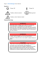
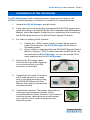
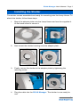
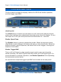
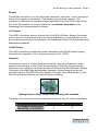
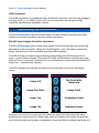
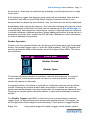
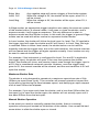
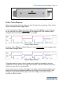
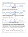
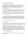
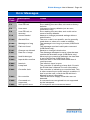
Page 2 · EQ-99 Manager User’s Manual Table of Contents Introduction ..................................................................................... 3 Safety Terms and Symbols ............................................................ 3 Installation ....................................................................................... 5 Installing the Shutter ....................................................................... 7 Front and Rear Panel ...................................................................... 8 Operating the Instrument.............................................................. 10 Menu Settings ............................................................................... 15 Specifications ................................................................................ 16 Remote Operation ........................................................................ 17 The USB Interface ......................................................................... 19 Alphabetical List of Commands ................................................... 20 Error Messages ............................................................................. 29 Maintenance and Service ............................................................. 30 Warranty ........................................................................................ 31 EQ-99 Manager User’s Manual · Page 3 Introduction The Energetiq EQ-99 Manager is a smart control system for operating the EQ99 Laser Driven Light Source and optional shutter. The front panel has LED indicators for the lamp on/off state and shutter position, and the VFD display provides additional status indication as well as the ability to change the operation of the instrument by adjusting the instrument settings through the menu. A trigger input on the front panel allows for synchronization of the shutter with other instruments, with exposure mode control or simply open/close operation. A USB interface is available for full operation from a computer. The Energetiq EQ-99 Manager also provides the 12VDC power needed by the EQ-99 Power Supply Controller. Safety Terms and Symbols The following safety-related terms are used in this manual: Warnings (noted by the WARNING heading) explain dangers that could result in physical injury or death; Cautions (noted by the CAUTION heading) explain conditions that could result in damage to the instrument, other equipment, or your device. Notes (noted by the NOTES heading) are not safety-related, and are intended simply to point out important information. If, at any time, any of the following conditions exist, or are suspected of existing, discontinue use of the unit until it can be inspected by qualified service personnel: Visible damage to the unit, including damage or stress caused during product shipment; Storage of the unit outside the standard storage temperature or humidity rating, or prolonged storage under harsh conditions; Failure to operate properly. If needed, contact your distributor or Energetiq for service or repair to ensure the safety of the product is maintained. Page 4 · EQ-99 Manager User’s Manual Symbols Power Off Power On Caution, refer to manual Earth ground Caution, risk of electric shock General Warnings WARNING Potentially lethal voltages exist within this instrument. This instrument is intended for use by qualified personnel who understand the shock and laser hazards and are familiar with safety procedures required to avoid injury. Read this manual completely before attempting to use this product. WARNING To avoid electrical shock, ensure a 3-prong power cord is used, and is plugged into an earth-grounded receptacle. Failure to do so can result in severe injury or death. CAUTION There are no user-serviceable parts inside. All service and repair work shall be done by Energetiq or personnel authorized by Energetiq. Modifications done by non-authorized personnel will void the warranty. Please see the Service section later in this manual for instructions on how to obtain service for this instrument. EQ-99 Manager User’s Manual · Page 5 Installation of the Controller The EQ-99 Manager uses a switching power supply which supports 100240VAC, 50/60Hz operation, so there is no need for AC voltage selection. 1. Unpack the EQ-99 Manager and all cables. 2. If you have not done so already, unpack the EQ-99 LDLS system and setup according to the Model EQ-99 LDLS Operation and Maintenance Manual, which has specific instructions on unpacking and connecting the EQ-99 Lamp House to the EQ-99 Power Supply Controller. 3. For users of existing LDLS systems: a. b. Unplug any 12VDC power supply currently being used to power the controller. The EQ-99 Manager will provide all necessary power. If your system is equipped with the EQ-99-RC Remote Control Module, unplug it. The I/O cable used with the EQ-99-RC can be used with the EQ-99 Manager, or you can use the HD15 cable supplied with the EQ-99 Manager. 4. Connect the DC power cable. This has the 2-pin 2W2 connector on one end and the 4-pin DIN connector on the other. 5. Connect the I/O cable. This has a HD15 male connector on each end. If you were previously using the EQ-99-RC Remote Control Module, the cable for that module can also be used. 6. Connect the interlock. The system ships with an interlock plug already pre-shorted (a wire connecting the two pins), however, if you have an interlock system, remove the wire and connect your interlock into it. Insert the plug into the interlock socket. Page 6 · EQ-99 Manager User’s Manual 7. 8. Optional: if you have purchased a shutter, see Installing the Shutter, below, for shutter installation instructions. Plug the AC cord into the unit and into the wall outlet. Turn on the power switch located on the rear panel next to the AC socket, and both the EQ-99 Manager and the EQ-99 Power Supply Controller will power up. If you wish to control the instrument from your computer, connect the instrument to your computer and install the USB drivers. When the Add New Hardware wizard appears, if your computer is Internet-connected, you can use Windows Update to load the driver; otherwise, insert the CD you received with the instrument. Follow the on-screen instructions. Once the drivers are installed, a COM port number will automatically be assigned to the controller, typically the highest COM port in the system. Ventilation The EQ-99 Manager has vent holes on both sides of the unit. You must not block these vent holes or overheating may occur, causing damage to the unit. CAUTION Do not operate the unit above +40°C ambient, and ensure the instrument is properly ventilated, or the unit may overheat and possible damage to the unit may occur. Rack Mounting Rack mounting kits (p/n 1401-RM-1 or p/n 1401-RM-2) for standard 19” racks are available for the EQ-99 Manager, and supports the rack mount of one (1401-RM-1) or two (1401-RM-2) units in a 2U (3.5”) high opening. EQ-99 Manager User’s Manual · Page 7 Installing the Shutter The shutter comes assembled and ready for mounting onto the Lamp House. To attach the shutter, follow these steps: 1. Mount the adapter plate onto the Lamp House and use the supplied 440 flat head screw to secure it: 2. Next mount the shutter housing onto the adapter plate: 3. Finally, secure the shutter to the adapter plate by tightening the retaining screw: 4. Plug the cable into the EQ-99 Manager. The shutter is now ready for use. Page 8 · EQ-99 Manager User’s Manual Front and Rear Panel The front panel includes the display, buttons for LDLS and shutter operation, and the trigger input BNC: LDLS Control Interface Front Panel LDLS On/Off The LDLS button is used to turn the lamp of or off, and is also used to exit the menu when making menu adjustments and clear errors from the display. To turn the output on or off, you must press and hold the button for ½ second. Shutter Open/Close The Shutter button is used to operate the shutter. When the exposure mode (Exp Mode) is set to Manual, the button will open or close the shutter. When the exposure mode is set to Exposure, the button will act as a trigger, causing one exposure to be taken. Shutter Trigger BNC This is a 0V to 5V level or edge sensitive input used to open and close the shutter remotely. The shell is ground and the center pin is the signal input. For more information on shutter operation, see Shutter Operation in the Operating the Instrument section below. All connections except the trigger input BNC are located on the rear panel: LDLS Control Interface Rear Panel EQ-99 Manager User’s Manual · Page 9 Shutter The shutter connector is a mini-XLR type connector, with pins 1 and 2 providing the control signals to the shutter. The remaining 3 pins are unused. This interface is used with the optional shutter attachment for the LDLS lamp house. For more information on shutter operation, see Shutter Operation in the Operating the Instrument section below. I/O Control This HD15 connector mirrors the pin-out of the EQ-99 Power Supply Controller, and is used to monitor and control the lamp operation. For more details on the pin-out and operation of this interface, see the Model EQ-99 LDLS Operation and Maintenance Manual. 12VDC Power This 2W2 connector provides the power needed by the EQ-99 Power Supply Controller for operation. Pin 1 is ground, and pin 2 is 12VDC. Interlock The interlock input is a 2-pin Phoenix connector, and provide access to the interlock functionality of the EQ-99 Power Supply Controller. By connecting these two pins together, the external interlock input to the EQ-99 Power Supply Controller is brought high and enables operation. When these pins are not shorted together, the EQ-99 Power Supply Controller Fault LED will be lit, and the front panel will indicate an interlock open condition. Mating Phoenix Plug - shown with shorting wire installed The pins of the interlock are connected to the pins of the I/O Control as follows: Function EXTERNAL INTERLOCK ISOLATED +5V SUPPLY Interlock Pin 1 2 I/O Control Pin 13 5 Connection between Interlock and I/O Control Page 10 · EQ-99 Manager User’s Manual USB Connector The USB connector is a standard Type B female connector, and can be plugged into any USB 1.1 or USB 2.0 port. For more information on using the USB interface, see Remote Operation, below. Operating the Instrument The EQ-99 Manager can be broken down into two sections: the EQ-99 Power Supply Controller operation and the shutter operation. EQ-99 Power Supply Controller Operation The EQ-99 Manager both controls the output of the lamp as well as monitoring the status of the controller. Using the On/Off button, you can easily control the lamp, and control is also available over the USB interface. The LDLS lamp is turned on by pressing and holding the LDLS button for at least 1 second then release. The green On LED will illuminate, and the lamp will start the turn-on process. Likewise, to turn off the lamp, press and hold the LDLS button for 1 second then release. The VFD display will indicate the state of the lamp with one of the following icons: Icon Normal States Icon Fault States Lamp Off No Controller Detected Lamp Pre-Start Lamp Fault Laser On Controller Fault Lamp On Interlock Open During a normal turn-on process, the lamp will start from the Lamp Off state, briefly move to the Lamp Pre-Start state, then will dwell at the Laser On state for up to two minutes as the laser is stabilized. Once the laser is stable, the lamp will EQ-99 Manager User’s Manual · Page 11 be turned on, the Lamp On state will be indicated, and the light source is ready to be used. If the interlock is open, the interlock open state will be indicated. Note that the Controller Fault LED on the EQ-99 Power Supply Controller will be lit, but because fault is caused by the interlock, only the interlock icon will be displayed. Immediately after closing the interlock, the controller interface will indicate a fault for a brief period of time until the fault can be cleared by the EQ-99 Manager. A controller fault that persists for more than a couple of seconds after the interlock is closed indicates a different problem. When dealing with either a lamp fault or a persistent controller fault, consult the EQ-99 User’s Manual for more information on how to address this problem. Shutter Operation Control over the optional shutter can be done one of three ways: the front panel button, the shutter trigger input, or over the USB interface. The VFD display will actively remote the state of the shutter, as will the Open/Close LEDs. The icons are as follows: Icon Shutter State Shutter Closed Shutter Open The shutter offers two modes of operation: manual and exposure. In manual mode, a press of the shutter button will open or close the shutter, and the shutter will remain in that state. In exposure mode, the shutter is opened for a defined exposure time and then closed. Pressing the shutter button when the shutter is closed will open the shutter and automatically close the shutter after the programmed exposure time. Pressing the shutter button while the shutter is open will immediately close the shutter. The Shutter Trigger input BNC on the front of the unit provides an external trigger input for synchronizing the shutter with external events. The trigger can be configured for either edge or level sensitivity. There are four trigger modes: Edge, Pos Any positive edge will cause a trigger of the shutter system. Page 12 · EQ-99 Manager User’s Manual Edge, Neg Level, Pos Level,Neg Any negative edge will cause a trigger of the shutter system. When the voltage is 5V, the shutter will be open, when 0V, it will be closed. When the voltage is 0V, the shutter will be open, when 5V, it will be closed. In Edge modes, an appropriate trigger transition acts nearly the same as a press of the shutter button: in manual mode, it will open or close the shutter, and in exposure mode, it will trigger an exposure. The only difference is when in exposure mode and the shutter is open: in this case, the trigger is ignored. Edge modes can be used with either manual or exposure shutter modes. In Level modes, the shutter will follow the level input. In Level, Pos, 5V applied to the trigger input will open the shutter and 0V will close it. In Level, Neg, the logic is reversed. When in either Level mode, the shutter button can be used to manually override the trigger level, but at the next transition, the manual override will be cleared and the trigger will again operate normally. Level modes can only be used in manual shutter mode. For example, if the instrument is configured for Level, Pos and 5V is applied to the trigger input, the shutter will open. If the user then presses the shutter button, the shutter will close, and remain closed, even though the trigger input is at 5V; this is considered a manual override. However, once the trigger input goes to 0V, the manual override will be cleared, and the next transition to 5V will open the shutter. Maximum Shutter Rate The shutter is only designed to operate at a maximum open/close rate of 2Hz (500ms per open/close cycle). The controller will prevent operation beyond this cycle rate by monitoring the time between opens, and delaying an open request until at least 500ms has elapsed. For example, if you open and close the shutter, and in less than 500ms after the last open, try to open the shutter again, the shutter will not actually open until it has been 500ms since the last open. Manual Shutter Operation In the event you need to manually operate the shutter, there is a manual operation access port located on the bottom of the shutter. Use a small flat-bad screw driver to slide the shutter open or closed. EQ-99 Manager User’s Manual · Page 13 Manual Operation Port and three post-mounting holes Shutter Timing Diagrams Below are a series of timing diagrams that illustrate the operation of the shutter when controlled by the trigger input. In this first diagram, Trig is set to Pos, Edge, and the Shutter is set to Manual. As you can see, for every rising edge of the trigger input, the shutter output changes state (closed to open or open to closed): Shutter Open Shutter State Shutter Closed 5V Trigger Input 0 200 400 600 800 1000 1200 1400 1600 1800 0V 2000 Positive Edge, Manual Likewise, with a Trig set to Neg, Edge, for every falling edge of the trigger input, the shutter changes state: Shutter Open Shutter State Shutter Closed 5V Trigger Input 0 200 400 600 800 1000 1200 1400 1600 1800 0V 2000 Negative Edge, Manual The graphs above show a much longer pulse width for readability, but the instrument is very sensitive to trigger input pulses and can operate with pulse widths as short as 10 microseconds. Level modes do not monitor the edges, but rather the level of the trigger input, opening or closing the trigger based on the voltage. For positive level, if the voltage is high, the shutter is open, and if the voltage is low, the shutter is closed, as shown below: Page 14 · EQ-99 Manager User’s Manual Shutter Open Shutter State Shutter Closed 5V Trigger Input 0 200 400 600 800 1000 1200 1400 1600 1800 0V 2000 Positive Level Likewise, with a negative level, the logic is reversed, and the shutter is open when voltage is low and closed when voltage is high: Shutter Open Shutter State Shutter Closed 5V Trigger Input 0 200 400 600 800 1000 1200 1400 1600 1800 0V 2000 Negative Level When using the timed exposure mode, you specify how long the shutter is to remain open for each trigger. Exposure timing is only valid for edge (positive or negative) trigger modes. Below is a timing diagram of positive edge trigger mode and an exposure time of 200ms: Shutter Open Shutter State Shutter Closed 5V Trigger Input 0 200 400 600 800 1000 1200 1400 1600 1800 0V 2000 Positive Edge, Exposure = 200ms Care should be taken to ensure your trigger input does not exceed the 2Hz (500ms) operating speed of the shutter. Operating above that rate will lead to unexpected exposure times. Below is an example of shutter operation with a positive edge input in manual mode. As you can see, the shutter does not open on every other pulse, as you would expect, but rather, the instrument delays the opening until the 500ms after the last open trigger, leading to the varied exposure times: Shutter Open Shutter State Shutter Closed 5V Trigger Input 0 200 400 600 800 1000 1200 1400 1600 1800 0V 2000 Positive Edge, Manual, Trigger Speed Exceeds Shutter Capability EQ-99 Manager User’s Manual · Page 15 Menu Settings The EQ-99 Manager has a very simply menu interface, but it does allow changes in operation without needing a PC to make the adjustment. To enter the menu, press and hold the Shutter button. Once the menu is displayed, you can release the button. To cycle through the menu items, press and release the Shutter button. To change a menu setting, press and hold the Shutter button until an asterisk (*) shows up to the right of the setting, then release the button. Once the asterisk is display, you can change settings by pressing and releasing the shutter button. Once you have changed the setting to the desired value, again press and hold the shutter button until the asterisk disappears. You can continue to cycle through the menu. Pressing the LDLS button at any time will exit the menu. If you were in the middle of making a setting change, it will be saved. The following menu settings are available (default values are indicated in bold): Setting Trig Shutter Exp Time Shutter Init Lamp Time Reset Lamp Time S/N Description Trigger Mode – selects the sensitivity of the trigger input BNC. Shutter Mode – selects manual or time controlled exposure. Exposure Time This is only displayed if Shutter Mode is set to Exposure) The initial state of the shutter on power-up. The cumulative number of hours the LDLS has been on. Resets the lamp time to zero. Serial number of the instrument. Value Range Edge, Pos Edge, Neg Level, Pos Level, Neg Manual or Exposure 100ms to 30000ms Closed or Open 0.00 to 9999.00 No or Yes Page 16 · EQ-99 Manager User’s Manual Specifications Description EQ-99 Manager Power Voltage Maximum Current Connector I/O Control Connector Interlock Mating Connector Specifications 12V 10A 2W2 Female HD15 Female Phoenix 1827703 Shutter Control Connector Voltage Current Maximum Cycle Rate Exposure Window Trigger Connector Voltage Minimum Trigger Pulse Width Switchcraft Mini-XLR Female 10.7V 1.5A (typical) 2 Hz 100 ms to 30 s BNC, center positive 0V or 5V 10 microseconds General Indicators Display Computer Interface AC Power Size (H x W x D) [inches (mm)] Operating Temperature Storage Temperature Weight LEDs for LDLS and shutter status VFD, 2x20 USB 2.0 Full Speed (Type B) 84-264VAC, 50/60Hz, 150W 1.82(47) x 8.5(215) x 11(280) +10°C to +40°C -20°C to +60°C 3.4 lbs (1.6kg) EQ-99 Manager User’s Manual · Page 17 Remote Operation While the instrument does not have a GPIB interface, the command structure and parsing were developed around the IEEE-488.2 standard, and the command/response format is consistent with the standard. When sending commands to the instrument, you must terminate the command string with a carriage return (ASCII 13) or line feed (ASCII 10), or both. The instrument will not start processing a command, or go into remote mode until it has received a carriage return or feed command terminator. Commands are grouped into two major categories: device-independent and device-dependent commands. Device-independent commands include all the IEEE-488.2 supported commands plus other commands that are universal across all instruments. Device-dependent commands are specific to a class of instruments, such as LDLS commands for the EQ-99 Power Supply Controller. Device-Independent Commands The following device-independent commands are supported: *IDN? *RST BEEP BEEP? BRIGHT BRIGHT? DELAY ERRors? ERRSTR? MESsage MESsage? REMERR REMERR? SN? TIME? TIMER? VER? Device-Dependent Commands Device-dependent commands are specific to a class of instruments, in this case, LDLS control. LDLS Command List LDLS:COND? LDLS:EVEnt? LDLS:EXPosure LDLS:EXPosure? LDLS:EXPMODE LDLS:EXPMODE? LDLS:OUTput LDLS:OUTput? LDLS:LAMPTIME LDLS:LAMPTIME? LDLS:SHUTINIT LDLS:SHUTINIT? LDLS:SHUTter LDLS:SHUTter? LDLS:TRIGMODE LDLS:TRIGMODE? Page 18 · EQ-99 Manager User’s Manual Command Syntax and Concatenation All commands use a common syntax for constructing the command and parameter passing. Commands are case-insensitive, and some commands have optional characters, which are denoted as lower-case characters in the command definition. For example, LDLS:EVEnt? can be shortened to LDLS:EVE? This allows for command abbreviation and therefore reduced communication times. The input buffer of the instrument allows for up to 128 characters to be received before a command overflow error occurs. If a command overflow does occur, the entire buffer is discarded and an E-102 (Message too long) error will occur. If a command requires one or more parameters, place a space between the command and the first parameter, then use a comma to separate additional parameters. For example, the lamp output on command might look like: LDLS:OUTPUT 1 It is also possible to concatenate multiple commands together as a single communication to the instrument. By using a semicolon, multiple commands can be sent to the instrument at once, but command processing will not start until all commands and the command terminator have been received. For example, to open the shutter and turn on the lamp, the command would look like: LDLS:SHUTTER 1;LDLS:OUTPUT 1 Command Paths The command set is structured in a tree-like organization, where commands for a common device or function are grouped together. For example, all commands specific to the LDLS start with a “LDLS:” prefix. This is called the command path. When issuing multiple concatenated commands to the instrument, it “remembers” the command path of the previous command, and allows you to omit the common path from the second command. Using the example above, where the shutter was opened and the output turned on, it could also be shortened by omitting the second “LDLS:” portion because when the OUTPUT command is processed, the command parser “remembers” it’s position in the command tree and starts looking for the command at that level. The command could therefore be shortened to this: LDLS:SHUTTER 1;OUTPUT 1 Removing the optional characters from the commands, you can further shorten the command to: EQ-99 Manager User’s Manual · Page 19 LDLS:SHUT 1;OUT 1 Numeric Substitutions For command readability, you can also substitute alternate values for zero (0) and one (1). “0” can be replaced by “CLOSED”, “OFF”, “NEW”, or “FALSE”. “1” can be replaced by “OPEN”, “ON”, “OLD”, or “TRUE”. The USB Interface Because of its speed, expandability, and commonality, the USB interface has become the interface of choice for newer PC-connected devices. Unlike GPIB, USB uses inexpensive cables and allows up to 127 devices to be connected to a single USB master. To keep complexity to a minimum, once you have installed the USB drivers, the instrument will appear as a virtual serial port that you can use just like a normal serial port. In this way, you can communicate to the instrument without requiring special software modifications to your existing applications. Unlike the RS232 interface, using the USB interface requires software drivers (provided on the CD with your instrument or available over the Microsoft Windows Update service) to be loaded onto your PC. Follow the instructions in your instrument manual for installing the USB drivers. Once a COM port has been assigned to an instrument, it will continue to use the same COM port unless it is reassigned through the Control Panel. Cable Connections and Interface Settings The EQ-99 Manager uses a full-size USB Type B socket. You may use any USB 1.1 or 2.0 certified cable. The baud rate is fixed at 38,400. Baud Rate Parity Data Bits Stop Bits Flow Control 38400 None 8 1 None Ensure to disable flow control. Failure to do so will prevent the instrument from sending data back to the PC. Page 20 · EQ-99 Manager User’s Manual Alphabetical List of Commands *IDN? Synopsis Query the instrument identification Syntax *IDN? Details Returns the identification string for the instrument in the following format: Energetiq Model SN Ver Build Response Model SN Ver Build Description The model number of the product, such as ‘EQ99-CONT’. The serial number. The firmware version. Internal build number. *RST Synopsis Reset command Syntax *RST Details Resets the instrument to factory defaults, and the output is shut off. The unit remains in remote mode. See Also *RCL BEEP Synopsis Set the beep enable Syntax BEEP [enable] Details Causes the instrument to beep, or enables or disabled the beep sound for error messages and other events that generate and audible response. If enable is omitted, it is the equivalent of doing a ‘BEEP 2’. Argument enable See Also Value 0 1 2 Description Disable the beep sound Enable the beep sound Generate one beep BEEP? BEEP? Synopsis Query the beep enable Syntax BEEP? Details Returns the value of the Beep register. EQ-99 Manager User’s Manual · Page 21 Response enable See Also BRIGHT Value 0 1 Description Disable the beep sound Enable the beep sound BEEP Synopsis Set the display brightness Syntax BRIGHT brightness Details Sets the display brightness level, from 0 to 100 percent. Argument brightness Value 0 to 100 Description Brightness level of the display There are only 8 brightness levels, and the brightness parameter will be used to select an appropriate level. See Also BRIGHT? BRIGHT? Synopsis Query the display brightness Syntax BRIGHT? Details Returns the value of the display brightness. See the BRIGHT command for more details. See Also BRIGHT DELAY Synopsis Causes a delay in command processing Syntax DELAY time Details Causes command processing to be delayed for the specified number of milliseconds. Argument time Value 1 to 30000 Description Delay, in milliseconds ERRors? Synopsis Query for errors Syntax ERRors? Details Returns a comma–delimited list of error codes. If no error has occurred, a 0 is returned. Page 22 · EQ-99 Manager User’s Manual A typical response might look like: 201,124 See Also ERRSTR? ERRSTR? Synopsis Query for errors with string descriptions Syntax ERRSTR? Details Similar to the ERR? query, but a string description is included with the error code. A typical response might look like: 201,“Out of range”,124,“Data mismatch” See Also ERR? LDLS:COND? Synopsis Query LDLS condition register Syntax LDLS:COND? Details Returns the LDLS condition register. The condition register reflects the state of the instrument at the time the condition register is read. Response conditions See Also Bit 0 1 2 3 4 5 6 7 8 Value 1 2 4 8 16 32 64 128 256 Description Interlock Controller not detected Controller fault Lamp fault Output on Lamp on Laser on Laser stable Shutter open LDLS:EVEnt? LDLS:EVEnt? Synopsis Query LDLS event register Syntax LDLS:EVEnt? Details Returns the LDLS event register. The event register reflects the occurrence of any condition since the last time the event register was read. For example, if the output was turned on and then turned off, the Output on bit in the condition register will be zero, but the same bit in the event register will be one. EQ-99 Manager User’s Manual · Page 23 Response events See Also Bit 0 1 2 3 4 5 6 7 8 Value 1 2 4 8 16 32 64 128 256 Description Interlock Controller not detected Controller fault Lamp fault Output on Lamp on Laser on Laser stable Shutter open LDLS:COND? LDLS:EXPosure Synopsis Set the exposure time Syntax LDLS:EXPosure time Details Exposure time is set in milliseconds. Exposure time is used when the shutter exposure mode is set Exposure (1). An exposure is triggered by a shutter button press or the shutter trigger input. Argument time See Also Value 100 to 30000 Description Exposure time, in milliseconds LDLS:EXPosure?, LDLS:EXPMODE LDLS:EXPosure? Synopsis Query the exposure time Syntax LDLS:EXPosure? Details Returns the exposure time, in milliseconds. See LDLS:EXPosure for more details. See Also LDLS:EXPosure LDLS:EXPMODE Synopsis Set the exposure mode Syntax LDLS:EXPMODE mode Details Set the exposure mode (same as the Shutter setting in the menu). Argument mode See Also Value 0 1 LDLS:EXPMODE? Description Manual mode Exposure mode Page 24 · EQ-99 Manager User’s Manual LDLS:EXPMODE? Synopsis Query the exposure mode Syntax LDLS:EXPMODE? Details Returns the exposure mode. See LDLS:EXPMODE for more details. See Also LDLS:EXPMODE LDLS:OUTput Synopsis Turn the output on or off Syntax LDLS:OUTput enable Details Turns the lamp output on or off. Argument enable See Also Value 0 1 Description Turns the output off Turns the output on LDLS:OUTput? LDLS:OUTput? Synopsis Query the lamp output state Syntax LDLS:OUTput? Details Returns the output state. Will return true as soon as the turned on process has started, even if the lamp has not yet turned on. To determine the lamp and laser state, use the LDLS:COND? query. See Also LDLS:OUTput, LDLS:COND? LDLS:LAMPTIME Synopsis Set the lamp runtime Syntax LDLS:LAMPTIME time Details Resets the runtime to the new value. Useful for resetting the runtime to zero when the lamp has been serviced or replaced, or when moving the manager to a new LDLS system. Argument time See Also Value 0 to 999 LDLS:LAMPTIME? LDLS: LAMPTIME? Synopsis Query the lamp runtime Syntax LDLS: LAMPTIME? Description Runtime, in hours EQ-99 Manager User’s Manual · Page 25 Details Returns the number of hours accumulated while the lamp was on. Value is in hours. See Also LDLS:LAMPTIME LDLS:SHUTINIT Synopsis Set the power-up shutter state Syntax LDLS:SHUTINIT state Details Sets the initial state of the shutter on power-up of the manager. Argument state See Also Value 0 1 Description Shutter is closed on power-up Shutter is open on power-up LDLS:SHUTINIT? LDLS:SHUTINIT? Synopsis Query the power-up shutter state Syntax LDLS:SHUTINIT? Details Returns the power-up shutter state. See LDLS:SHUTINIT for more details. See Also LDLS:SHUTINIT LDLS:SHUTter Synopsis Open, close, or trigger the shutter Syntax LDLS:SHUTter state Details A close command (state equals 0) will always close the shutter, regardless of exposure mode. An open command (state equals 1) will open the shutter if exposure mode is set to Manual, or trigger a shutter if exposure mode is set to Exposure. Argument state See Also Value 0 1 Description Close the shutter Open or trigger the shutter LDLS:SHUTter? LDLS:SHUTter? Synopsis Query for errors with string descriptions Syntax LDLS:SHUTter? Details Returns the state of the shutter. Page 26 · EQ-99 Manager User’s Manual Response state See Also Value 0 1 Description Shutter is closed Shutter is open LDLS:SHUTter LDLS:TRIGMODE Synopsis Set the trigger mode Syntax LDLS:TRIGMODE mode Details The trigger mode controls how the shutter trigger input controls the operation of the shutter. For more information on trigger modes, see Shutter Operation in the Operating the Instrument section earlier in this manual. Argument mode See Also Value 0 1 2 3 Description Positive edge trigger Negative edge trigger Positive level trigger Negative level trigger LDLS:TRIGMODE? LDLS:TRIGMODE? Synopsis Query the trigger mode Syntax LDLS:TRIGMODE? Details Returns the trigger mode. See LDLS:TRIGMODE for more details. See Also LDLS:TRIGMODE MESsage Synopsis Set the message buffer Syntax MESsage string Details Sets the internal message buffer to the value of string, up to a maximum of 16 characters. See Also MESsage? MESsage? Synopsis Query the message buffer Syntax MESsage? Details Returns the value of the message buffer. See Also MESsage EQ-99 Manager User’s Manual · Page 27 REMERR Synopsis Set display of errors while in remote mode Syntax REMERR enable Details This command controls if the instrument will display errors while in remote mode. If set to zero, then errors will not be displayed. If set to one, errors will be displayed. Errors will always accumulate in the error queue. Argument enable See Also Value 0 1 Description No not display errors in remote mode Display errors in remote mode REMERR?, ERR?, ERRSTR? REMERR? Synopsis Query the display of errors while in remote mode Syntax REMERR? Details Returns the current REMERR setting. See the REMERR command for a complete definition of possible return values. See Also REMERR SN? Synopsis Query the serial number of the instrument Syntax SN? Details Returns the serial number of the instrument. This is the same information that is part of the *IDN? query. See Also *IDN? TERM Synopsis Set response terminator Syntax TERM terminator Details This command controls the termination characters used for responses to queries. Page 28 · EQ-99 Manager User’s Manual Argument terminator See Also Value 0 or 1 2 or 3 4 or 5 6 or 7 Description <CR><LF> <CR> <LF> no terminator TERM? TERM? Synopsis Query response terminator Syntax TERM? Details Returns the current response terminator setting. See the TERM command for a complete definition of possible return values. See Also TERM TIME? Synopsis Query run time Syntax TIME? Details Returns the elapsed time since the unit has been turned on. Format is in HH:MM:SS.ss, where HH is hours, MM is minutes, SS is seconds, and ss is hundredths of a second. See Also TIMER? TIMER? Synopsis Query time since last TIMER? Syntax TIMER? Details Returns the elapsed time since the last TIMER? query was received, or, if this is the first TIMER? query, the time since unit has been turned on. Format is in HH:MM:SS.ss, where HH is hours, MM is minutes, SS is seconds, and ss is hundredths of a second. See Also TIME? VER? Synopsis Query the firmware version Syntax VER? Details Returns the firmware version. This is the same information that is part of the *IDN? query. See Also *IDN? EQ-99 Manager User’s Manual · Page 29 Error Messages Error Code Description Cause E-3 E-4 Factory EE bad User EE bad E-5 User reset E-6 E-10 User EE bad, no recovery Access denied E-100 General Error E-102 Message too long E-123 Path not found E-127 E-201 Change not allowed Data out of range E-202 Invalid data type E-303 Input buffer overflow E-600 E-601 Interlock Lamp fault E-602 Controller fault E-603 No controller E-998 Command not supported Non-specific error Error reading the factory data. Error reading the user data, unit reset to factory defaults. Unit reset to factory defaults (not an error, notification only). Error reading the user data, and could not be reset to factory defaults. Attempt to change protected settings without authorization. The error code is non-specific, and is generally used when no other error code is suitable. The message is too long to process (USB/Serial only). The message used an invalid path command (USB/Serial only). Attempt to change locked value The message attempted to set a value that was outside the allowable range (USB/Serial only). When trying to parse the message, the data was in an invalid format (USB/Serial only). Data was sent to the instrument faster than it could process. The interlock input is open. The controller is indicating a lamp fault. Consult the EQ-99 User’s Manual for more information. The controller is indicating a controller fault. This is often caused by an open interlock condition. If that is not the case, consult the EQ-99 User’s Manual for more information. The EQ-99 Power Supply Controller was not detected. A command was recognized but not supported by the instrument. A non-specific error was encountered. E-999 Page 30 · EQ-99 Manager User’s Manual Maintenance and Service Maintenance The EQ-99 Manager requires no regular maintenance other than product calibration. To clean the instrument, use cotton cloth that is only damp (not wet) with a light solution of soap and water. Fuses Under normal operation, you should never need to replace a fuse. However, if either fuse does blow, use only T 250V, 2A, IEC 60127-2 5x20mm metric fuses as replacements. If, after replacing the fuse, it continues to blow, immediately discontinue use of the instrument and contact service for support. Service Service and repair for the EQ-99 Manager can be obtained by contacting the distributor from where you purchased the instrument, or directly from Energetiq. A complete list of distributors is available on the Energetiq web site. You can contact Energetiq through one of these methods: By mail: By phone: By fax: By email: On the web: Energetiq Technology, Inc. 7 Constitution Way Woburn, MA 01801 USA +1 (781) 939-0763 +1 (781) 939-0769 support@energetiq.com www.energetiq.com In all cases, Energetiq requires a return materials authorization (RMA) number. You must contact Energetiq and obtain an RMA number prior to returning your instrument, or the shipment may be rejected and sent back to you. EQ-99 Manager User’s Manual · Page 31 Warranty Energetiq Technology, Inc., warrants this product to be free from defects in material and workmanship under normal use and service for a period of one (1) year from date of shipment. It does not apply when the product has been misused, altered or damaged by accident or abnormal conditions of operation. If found to be defective during the warranty period, the product will either be repaired or replaced at Energetiq's option. THIS WARRANTY IS IN LIEU OF ALL OTHER WARRANTIES, EXPRESSED OR IMPLIED, INCLUDING IMPLIED WARRANTIES OF MERCHANTABILITY OR FITNESS FOR ANY PARTICULAR PURPOSE. ENERGETIQ SHALL NOT BE LIABLE FOR ANY INDIRECT, SPECIAL, OR CONSEQUENTIAL DAMAGES RESULTING FROM THE PURCHASE OR USE OF ITS PRODUCTS. Copyright © 2012, Energetiq Technology, Inc.. All Rights Reserved P/N 530-1035A