1
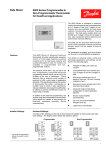
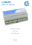
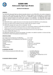
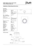
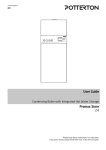
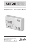
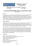
TP5E Electronic Programmable Room Thermostat USER INSTRUCTIONS INITIAL START-UP Slide the battery cover to the left to reveal the programming buttons (PROG, +, -). Slide the cover further left to reveal the battery compartment. Fig. 1 Fit the batteries (supplied) making sure the + ends align with the ⊕ symbols at the back of the compartment. RESET the TP5E as described below. The blank display changes to that shown in fig. 1. (If the actual air temperature in the proximity of the unit is higher than 20°C the flame symbol will not be displayed). Slide the battery cover to the right but leave the buttons visible. RESET The TP5E may be reset to the factory pre-set programme, 12:00 on day 1, and 20°C by pressing and holding down the four buttons, temperature s and t , time + and -, until the display becomes blank. This may be necessary after a severe electrical storm or serious fluctuations in the electricity supply, indicated by a malfunction or spurious information such as 18:88 on the display. SETTING THE CLOCK Press the PROG button once; the colon stops blinking, (see fig. 2). Use the + and - buttons to set the time. Pressing and releasing these buttons changes the time by one minute, holding these buttons down changes the time quickly. When the time is correct press the PROG button to start the clock; now only the colon and day number are displayed, (see fig. 3). Use the + and buttons to select the correct day number. (It is intended that day 1 is Monday, therefore days 6 and 7 are Saturday and Sunday - the weekend). Press PROG to display the first setting, (see fig. 4). REVIEWING THE EXISTING SETTINGS Now each press of the PROG button shows, in sequence, the twelve set times and their associated control temperatures, starting at setting 1, days 1 to 5, and finishing at setting 6, days 6 & 7, (see figs. 4 to 6). Pressing PROG while setting 6, days 6 & 7 is shown returns the TP5E to RUN mode. Fig. 2 The following table shows the factory pre-set programme, which may be re-instated at any time by performing a RESET. Days 1 to 5 (Weekdays) Setting 1 2 3 4 5 6 Time Temp. 6:30 8:30 11:30 13:30 16:30 22:30 20 15 20 15 21 15 Days 6 & 7 (Weekend) Setting Time Temp. 1 2 3 4 5 6 7:00 16:00 23:00 0:00 1:00 1:59 20 21 15 15 15 15 The factory pre-set programme for days 6 & 7 (Saturday and Sunday) provides full heating throughout the day until 23:00, after which the 15°C may be raised manually to the level required using the s button. The manual over-ride will last for up to one hour until midnight (0:00) after which it can be used up to twice again to provide full heating until 1:59 if required. CHANGING THE SETTINGS While reviewing the settings the switching time and control temperature may be changed using the + and (time) and s and t (temperature) buttons. When changing the switching times it is not possible to set the times out of sequence. This important feature works like this: Fig. 3 Both number 1 time settings can be placed at any time of the day, although they would usually be in the morning. Each of the time settings 2 to 6 can only be placed between the previous setting and 1:59. Fig. 4 Fig. 5 Fig. 6 When using the - button to change settings 2 to 6 the button stops responding when the previous setting time is reached. While using the + button to change settings 2 to 5, as later settings in the sequence are reached the time continues to advance, (until 1:59 if the button is held down), and all later settings reached are then changed to the same time as the one being set. Should this happen unintentionally and settings 2 to 6 are all at the same undesirable time, use the PROG button to get back to setting 1, days 1 to 5, then review and change all the times and temperatures to the required settings. If any times are intentionally set to the same time then the temperature associated with the higher setting number will be used to control the room temperature. 1 NOTE While in programming mode (but not in time setting), if no buttons are pressed for 2 to 3 minutes the TP5E automatically returns to RUN mode, and the programme set up to that moment will be active. This programme may not be the one intended so review the settings again, before returning to RUN by pressing PROG at setting 6, days 6 & 7. EVERYDAY OPERATION When all twelve time/temperature settings have been checked and/or altered, ensure the TP5E is in the RUN mode, with the colon blinking, (see fig. 7), before sliding the cover shut. Fig. 7 TIME OR TEMPERATURE DISPLAY The TP5E will always display the time and required temperature after a RESET. Once the switching times and temperatures have been set and the Fig. 8 unit returned to the RUN mode, the actual room temperature can be displayed instead of the time. To change between time and temperature display press the + and - buttons together. Fig. 8 is a typical temperature display showing the actual temperature, the required temperature, and flame and thermometer symbols. The flame symbol appears in either time or temperature displays when the TP5E is calling for heat. MANUAL OVER-RIDE The programmed control temperature may be changed temporarily using the s and t buttons until the required Fig. 9 temperature is shown. An s or t arrow will appear in the display as a reminder that the programmed setting has been overridden, (see fig. 8 again). This over-ride is cancelled at the next programmed switching. WEEKEND into WEEKDAY OVER-RIDE To use days 6 & 7 settings during any of days 1 to 5 press the s and t buttons together, (see fig. 9). This over-ride is cancelled by selecting Constant Temperature Control (see below) or when the time reaches 2:00. CONSTANT TEMPERATURE OVER-RIDE To set the TP5E to control at a constant temperature of 5°C press the s and t buttons together, once from Weekend/Weekday over-ride or twice from RUN mode. The required constant temperature may now be set using the s and t buttons, and can be anywhere in the range 5°C to 30°C. At 5°C a snowflake symbol appears in the display (see fig. 10) indicating frost protection mode*; at all other temperatures an s arrow appears (see fig. 11) indicating a constant temperature selection. This over-ride is cancelled by pressing the s and t buttons together. 2 Fig. 10 Fig. 11 *NOTE The TP5E will only provide frost protection to the area in which it is fitted. It WILL NOT provide frost protection in unheated areas, and may not provide frost protection in heated areas not controlled directly by the TP5E. BATTERY REPLACEMENT When the batteries approach the end of their life, a battery symbol blinks in the display (see fig. 12). When this Fig. 12 symbol appears both batteries should be replaced with high quality alkaline cells. 15 days after the symbol appears the TP5E will switch off. While the battery symbol is blinking the batteries may be changed without loss of time or programme. Have the new batteries unwrapped and ready, slide the battery cover fully off to the left, remove the old batteries and fit the new ones WITHIN FIVE MINUTES. Replace and close the battery cover. The TP5E will continue to function according to the automatic programme. Should the display ever become blank during normal operation the batteries will have to be renewed, the unit RESET, and the time, day and programme re-set as required. INSTALLATION INSTRUCTIONS NEW INSTALLATION Choose a fixing position where the TP5E will sense the room temperature without being affected by draughts or heat sources such as radiators, open fires of direct sunlight, see fig. 13. Fix at a height of approximately 1·5 metres from the floor. Cable entry is from behind if fitted to a single gang flush box; or from above, below or from the left if surface fixed cabling is used. Fig. 14 shows the fixing hole dimensions and the clearance required for removal of the sliding battery cover. Standard M3·5 screws are used to fix the TP5E to a flush box, or No.6 woodscrews and wallplugs of adequate length should be used for surface fixing. REPLACING AN ORDINARY ROOM THERMOSTAT Switch OFF the power supply to the heating system. Carefully note which wire colours are connected to which terminal numbers of the existing thermostat, and note the function of each terminal. If the existing thermostat has no indication of the function of each of its terminals, then a qualified electrician should be called before proceeding further. Remove the existing thermostats mounting plate from the wall, if applicable, and prepare the wall to receive the TP5E. Refer to fig. 14 for dimensions. Connect the wires to the TP5E as shown in fig. 15. Fig. 13 110 mm minimum from nearest obstruction If the existing wires are too short to connect to the TP5E then a pattress (PT05) should be fixed to the wall and used to terminate the existing wiring. New wires can then be extended from the pattress to the TP5E, which can then be fixed to the pattress with the screws provided. 60 mm fixing centres Fig. 14 NOTE. Some existing thermostats will have a Neutral wire and/or an Earth wire connected. These are not required by the TP5E and must not be connected to any TP5E terminals, but should be made electrically safe and coiled in the recess at the back of the TP5E. If in doubt about the function of any existing wire, call a qualified electrician for advice. Selecting the control mode The TP5E can operate either in on/off control mode or in chrono-proportional control mode. This is selected by means of a small link on the rear of the product (see fig.15 for location) The unit is factory set to on/off control with the link in place. When in on/off mode the thermostat cycles the heating on and off within its switching differential. If chrono-proportional control is selected the thermostat learns and attempts to reduce the switching differential thus improving comfort. t s Fig. 15 3 WIRING CONVERSIONS (see key to manufacturer below) TP2, 3, 4, 5 PET1 (P) TP1 (R) ON 3 1 OFF 2 2 COM 1 L B C A - - 2 1 2 1 3 4 N - N E CM5000 (H) N N E E RD3, RD3A, (R) R504 (R) RTC, RTM (D) RSR/M (R) RADI (L) 1 2 3 2 3 1 - E RTE (D) T6060B, T6160B (H) 2 3 3 4 1 1 4 2 - ON OFF COM N E TP2, 3, 4, 5 3 2 1 - - T4160B (H) 3 - 1 2 - TLX 2259 (S) 1 - 3 4 E TLX 2356 (S) 1 2 3 - E SRT2 (SW) 3 2 1 - 5 PRT1 (P) H - L N - PRT2 (P) H - TL N - (D) (H) (L) (P) (R) (S) (SO) (SW) Drayton Honeywell Landis & Gyr Potterton Randall Satchwell/Sunvic Sopac Switchmaster TECHNICAL SPECIFICATION Power supply - 2 x AA/MN1500/LR 6 High Quality Alkaline Batteries Switch Action - 1 x SPDT, Type 1B Switch Rating - 220/240 Vac, 50/60Hz, 6(2)A Control Temperature Range - TP5E, 5-30°C Maximum Ambient Temperature - 45°C Temperature Accuracy - ± 1°C Timing Accuracy - ± 1 minute/month Overall Dimensions (mm) - 99W, 81H, 34D Enclosure Rating - IP20 Control Pollution Situation - Degree 2 Rated Impulse Voltage - 2.5KV Ball Pressure Test - 75°C Designed to meet BS EN60730-2-9 This product complies with the following EC Directives: Electro-Magnetic Compatibility Directive. (EMC) (89\336\EEC), (92\31\EEC) Low Voltage Directive. (LVD) (73\23\EEC), (93\68\EEC) Danfoss Randall can accept no responsibility for possible errors in catalogues, brochures and other printed material, and reserves the right to alter its products without notice. This also applies to products already on order provided that such alterations can be made without subsequent changes being necessary in specifications already agreed. Danfoss Randall Ltd. Ampthill Road, Bedford, MK42 9ER Telephone: 01234 364621 Facsimile: 01234 219705 Email: danfossrandall@danfoss.com Website: www.danfoss-randall.co.uk 4 Part No: 6147 Issue 10 07/01