1
LUDLUM MODEL 2350-1
DATA LOGGER
May 2015
Serial No. 126167 and Succeeding
Serial Numbers
CPU Software Version 37122N16
Interface Software Version 37123N04
LUDLUM MODEL 2350-1
DATA LOGGER
May 2015
Serial No. 126167 and Succeeding
Serial Numbers
CPU Software Version 37122N16
Interface Software Version 37123N04
Table of Contents
1. INTRODUCTION .................................................................................................................................... 1
2. UNPACKING AND REPACKING.......................................................................................................... 2
3. SPECIFICATIONS ................................................................................................................................... 3
4. DESCRIPTION OF CONTROLS AND FUNCTIONS ........................................................................... 6
MAIN DISPLAY ........................................................................................................................................... 7
PARAMETER DISPLAY ................................................................................................................................ 8
DETECTOR DISPLAY ................................................................................................................................. 10
ALARM DISPLAY ...................................................................................................................................... 11
LOGGED DATA DISPLAY .......................................................................................................................... 11
LOGGED DATA LOCATION DISPLAY ........................................................................................................ 12
RECYCLE DATA DISPLAY ......................................................................................................................... 13
RECYCLE SETUP DISPLAY ........................................................................................................................ 15
MAXIMUM VALUES DISPLAY ................................................................................................................... 15
ERROR MESSAGE DISPLAY ...................................................................................................................... 16
COMMAND VERIFICATION DISPLAY ........................................................................................................ 17
OPTIONAL KEYPAD CONTROL ................................................................................................................. 18
5. SAFETY CONSIDERATIONS AND WARNING MARKINGS .......................................................... 19
ENVIRONTMENTAL CONDITIONS FOR NORMAL USE ............................................................................... 19
CLEANING INSTRUCTIONS AND PRECAUTIONS ........................................................................................ 19
WARNING MARKINGS AND SYMBOLS ...................................................................................................... 20
6. QUICK START ...................................................................................................................................... 21
LOADING THE MODEL 2350-1 COMMUNICATIONS SOFTWARE................................................................ 21
STARTING THE MODEL 2350-1 COMMUNICATIONS SOFTWARE .............................................................. 21
LOGGING DATA AND DUMPING TO A SPREADSHEET ............................................................................... 22
7. OPERATING PROCEDURES ............................................................................................................... 24
INITIAL PROCEDURES ............................................................................................................................... 24
BATTERY INSTALLATION ............................................................................................................................ 24
COMPUTER CONTROL SETUP ...................................................................................................................... 25
OPTIONAL KEYPAD SETUP .......................................................................................................................... 25
DETERMINING INSTRUMENT PLATEAU ....................................................................................................... 26
SETTING OPERATING PARAMETERS .......................................................................................................... 27
SETTING THE TIME OF DAY ................................................................................................................... 28
SETTING THE DATE ................................................................................................................................ 28
SETTING THE LOCATION CODE .............................................................................................................. 28
SETTING THE USER ID ............................................................................................................................ 29
DETECTOR SETUP ................................................................................................................................... 29
ALARM SETUP ........................................................................................................................................ 31
RECYCLE DATA SETUP........................................................................................................................... 32
SETTING RESPONSE TIME........................................................................................................................ 33
SETTING THE SECURITY CODE ................................................................................................................ 33
SETTING ACESS LEVELS ......................................................................................................................... 34
OPERATION COMMANDS ................................................................................................................... 34
8. SAMPLE APPLICATIONS ................................................................................................................... 44
RECYCLE MODE APPLICATIONS ............................................................................................................... 44
MAXIMUM VALUE WITH LOGGING PUSHBUTTON ................................................................................... 45
9. RECYCLING.......................................................................................................................................... 47
Model 2350-1 Data Logger
1
Section
Introduction
The Model 2350-1 Data Logger is a portable microprocessor-based counting
instrument designed for use with Geiger-Mueller (GM), proportional, and/or
scintillation detectors for measurement of alpha, beta, gamma, and/or neutron
radiation. Radiation data is presented in four ways:
1. Auto-ranging digital ratemeter
2. Timed counter (scaler)
3. Integrated dose counter
4. Five-decade logarithmic bar graph
All readouts operate from a single input, and each display can be enabled or
disabled if desired.
Up to 16 different sets of detector parameters can be stored, allowing for quick
changing of detectors or operating parameters. Detector readings can be stored
in the 1000 data point memory with identifiers for the date, time, sample
number, detector number, and the type of count that was logged. There are also
eight different location code identifiers, which include seven five-character
alphanumeric codes and a five-digit location coordinate. Other features include
individual alarms for each readout, click-per-event audio with audio divide and
volume control, voltage sensitive amplifier, single channel analyzer, adjustable
detector high voltage, adjustable window and threshold, detector overload
sensing circuitry, adjustable dead time compensation, calibration constant, and
response time.
Controlling the Model 2350-1 can be done by connection to a PC, optional
keypad, and/or optional bar code reader. The Model 2350-1 also has built-in
calibration sub-routines for calculating the calibration constant and dead time of
detectors.
The instrument readout is an 8-line by 15-character alphanumeric liquid crystal
display (LCD). A display backlight can be turned on or off by a toggle switch on
the front panel of the instrument. Batteries are externally accessible from the
back of the instrument housing for quick and easy replacement when necessary.
Ludlum Measurements, Inc.
Page 1
May 2015
Model 2350-1 Data Logger
2
Section
Unpacking and Repacking
Remove the calibration certificate and place it in a secure location. Remove the
instrument and accessories (batteries, cable, etc.) and ensure that all of the items
listed on the packing list are in the carton. If more than one instrument (Model
2350-1 and detector(s)) is in a carton, refer to the calibration certificate(s) for the
serial number (S/N) match. The Model 2350-1 S/N is located on the front-panel
below the acknowledgeable button. Most LMI detectors have a label on the base
or body of the detector for the Model and S/N identification.
To return the instrument for repair or calibration, provide sufficient packing
material to prevent damage during shipment and appropriate warning labels to
ensure careful handling.
Every returned instrument must be accompanied by an Instrument Return
Form, which can be downloaded from the Ludlum website at
www.ludlums.com. Find the form by clicking the “Support” tab and selecting
“Repair and Calibration” from the drop-down menu. Then choose the
appropriate Repair and Calibration division where you will find a link to the form.
Ludlum Measurements, Inc.
Page 2
May 2015
Model 2350-1 Data Logger
3
Section
Specifications
Compatible Detectors:
Connector:
Display:
Series C (others available on request)
8-line LCD display with 15 characters per line
Backlight:
Scaler:
GM, proportional, scintillation
a two-position toggle switch to activate backlight
six-digit display
used in conjunction with scaler. Count time can be set from 1 to
65,535 seconds in one-second intervals.
Timer:
Ratemeter:
digital ratemeter, corrected for dead time and calibration
constant
Trend Indicator:
Linearity:
five-decade logarithmic bar graph
reading within 10% of true value with detector connected
can display rem/hr, Sv/h, R/hr, cpm, cps, dpm, dps, rad(r), Gray (G),
C/kg, Ci/cm2, or Bq/cm2
Scale:
counter provided to give total accumulated dose for up to
45 days (will display in the same units as the ratemeter)
Integrated Dose:
built-in unimorph speaker with volume control (greater than 60 dB at
0.61 m {2 ft}, full volume)
Audio:
Audio Divide:
operator selected divisions of 1, 10, or 100 events per click
separate alarms for digital ratemeter, scaler, and integrated dose can
be set at any point (audible and visual indicators)
Alarm:
pushbutton to silence audio after alarm has been indicated
and/or scrolled through the various displays
ACK/Scroll:
Ludlum Measurements, Inc.
Page 3
May 2015
Model 2350-1 Data Logger
capable of logging up to 1000 individual data points with
following identifiers for each point: eight location codes, time of day, month,
day, and year, detector number, count rate/scaler count/integrated dose,
count time, logging mode, sample number
Data Logger:
Detector Parameters: capable of storing the following parameters for 16
different detectors: model number, serial number, calibration constant, dead
time correction, high voltage, threshold, window, display range multiplier,
display time base, display units, overload current, ratemeter alarm setting,
scaler alarm setting, scaler count time, integrated dose alarm setting
a full duplex communication port that allows for instrument
setup by optional keypad or PC, also allows for data to be transferred to a PC
file
RS-232 Port:
Bar Code Reader (optional):
allows for setup of instrument by computer
generated bar codes
High Voltage:
Threshold:
Window:
Gain:
adjustable from 400 to 2500 volts
adjustable from -100 to -1000 mV
adjustable from 0 to 1000 above threshold
adjustable from 2 to 350 mV at threshold setting of 100
Dead Time:
adjustable to compensate for dead time of detector and
electronics
Fixed response is adjustable from 1 to 127 seconds in one-second
intervals. Variable response will vary according to the number of counts
present. FAST is typically 4 to 25 seconds, and SLOW is typically 4 to 60
seconds from 10% to 90% of final reading.
Response:
four each D cell batteries (housed in sealed compartment that is
accessible from back of instrument)
Power:
Battery Life:
greater than 75 hours (low-battery condition is automatically
indicated)
Battery Dependence:
Construction:
less than 3% change in readings to battery end point
cast-and-drawn aluminum with beige polyurethane enamel
paint
Temperature Range:
Ludlum Measurements, Inc.
0 to 50 °C (32 to 122 °F)
Page 4
May 2015
Model 2350-1 Data Logger
14.2 x 11 x 22 cm (5.6 x 4.3 x 8.8 in.) (H x W x L) without handle, 20.9
cm (8.2 in.) (H) with handle
Size:
Weight:
Ludlum Measurements, Inc.
2.4 kg (5.2 lb), including batteries
Page 5
May 2015
Model 2350-1 Data Logger
4
Section
Ludlum Measurements, Inc.
Description of
Controls and Functions
Page 6
May 2015
Model 2350-1 Data Logger
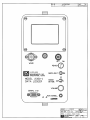
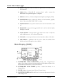
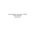
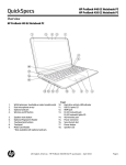
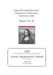
A. WAND: a plug that is used to connect an optional bar code reader want to
the instrument
B. SERIAL I/O: a 15-pin RS-232 connector that is used to connect the
instrument to the optional keypad to a computer
C. DISPLAY: an 8-line, 15-character alphanumeric liquid crystal display (LCD)
D. CONNECTOR: used to connect the detector to the instrument, typically
Series C, but can be BNC, MHV, UHF, or others
E. POWER SWITCH: a two-position switch used to turn the instrument on and
off
F. BACKILGHT: a two-position toggle switch that is used to turn the display
backlight on and off
G. AUDIO DIVIDE: a three-position toggle switch that is used to adjust the
audio divide between 1, 10, or 100 events per click
H. VOLUME: a one-turn potentiometer used to adjust the volume of the audio
I. ACK/SCROLL: a pushbutton that is used to silence the audible alarm
indicator and scroll through the various displays
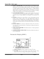
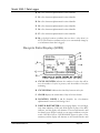
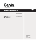
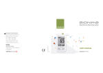
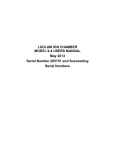
Main Display (SVD0)
A. INTEGRATED DOSE INDICATOR: provides total integrated dose
readout. In an alarm condition, the alarm indicator (ALM) displays in place of the
DOS indicator and alternates at one-second intervals.
B. INTEGRATED DOSE TIMER: provides a readout in minutes of an
integrated dose
C. CLOCK: displays the current time of day in 24-hours format
D. LOCATION CODES 1 & 2: identifies the five-character alphanumeric location
code settings 1 & 2
Ludlum Measurements, Inc.
Page 7
May 2015
Model 2350-1 Data Logger
E. DIGITAL RATEMETER: an auto-ranging display. Low and high-level alarm
indicators LOW and ALM appear in place of the RAT indicator, and the display
will alternate at one-second intervals until the alarm is reset. When overload or
over-range conditions occur, the words OVER LOAD or OVER RANGE
appear in place of the ratemeter, and the display will alternate at one-second
intervals until the condition is corrected. In the event an overload or over-range
condition occurs simultaneously, the overload message takes priority.
F. LOG BAR GRAPH DISPLAY: a bar-graph ratemeter display that is presented
in cps only and does not have dead time correction applied to it. The display
ranges from 1 cps to 100 kcps. (Note: The counting limit of the instrument is 50
kcps.
G. SCALER: a six-digit gross counter. When a count is being taken, the count
message (CNT) is shown in place of the scaler indicator (SCL). When the
instrument is in the data logging mode, the logging indicator (LOG) is displayed
in place of SCL. When in an alarm condition, the alarm indicator (ALM) displays,
and the display will alternate between the ALM and SCL indicators at one-second
intervals.
H. SCALER TIMER: The scaler timer is displayed on this line. The count time is
always displayed in seconds and will do a count-down to indicate the amount of
time left in the count.
I. DETECTOR IDENTIFIER: This identifies which set of detector parameters
is currently being used.
J. LOGGED READING INDICATOR: This indicator identifies the number of
the last reading logged.
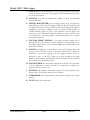
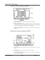
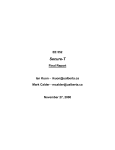
Parameter Display (SVD1)
A. HIGH VOLTAGE: provides a reading of the current HV setting
B. BATTERY: displays the current battery voltage. When the battery voltage
reads 4.4 volts or less, the message LOW replaces the voltage reading.
Ludlum Measurements, Inc.
Page 8
May 2015
Model 2350-1 Data Logger
C. CLOCK: displays the current time of day in 24-hour format. If the battery
voltage reads 4.4 volts or less, the message LO BAT alternates with the time
at one-second intervals.
D. USER ID: a 15-character alphanumeric display to allow for individual
operator ID codes
E. DIGITAL RATEMETER: an auto-ranging display. Low and high-level
alarm indicators LOW and ALM appear in place of the RAT indicator, and
the display will alternate at one-second intervals until the alarm is reset. When
overload or over-range conditions occur, the words OVER LOAD or
OVER RANGE appear in place of the ratemeter, and the display will
alternate at one-second intervals until the condition is corrected. In the event
an overload and over-range condition occurs simultaneously, the overload
messages takes priority.
F. LOG BAR GRAPH DISPLAY: a bar graph ratemeter display that is
presented in cps only and does not have dead time correction applied to it.
The display ranges from 1 cps to 100 kcps. Note: The counting limit of the
instrument is 50 kcps.
G. SCALER: a six-digit gross counter. When a count is being taken, the count
message (CNT) is shown in place of the scaler indicator (SCL). When the
instrument is in the data logging mode, the logging indicator (LOG) is
displayed in place of the SCL. When in an alarm condition, the alarm
indicator (ALM) displays, and the display will alternate between the ALM and
SCL indicators at one-second intervals.
H. SCALER TIMER: The scaler timer is displayed on this line. The count time
is always displayed in seconds and will do a count-down to indicate the
amount of time left in the count.
I. WINDOW: This identifies the window setting of the chosen detector. The
display reads OFF when the window is not activated.
J. THRESHOLD: This display indicates the threshold setting of the chosen
detector.
K. DATE: displays the current date
Ludlum Measurements, Inc.
Page 9
May 2015
Model 2350-1 Data Logger
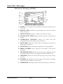
Detector Display (SVD2)
A. MODEL: used to identify the model number of the detector being used (442, 44-3, etc.)
B. DISPLAY UNITS: identifies the current display units used by the detector
(R, Sv, counts, etc.)
C. HIGH VOLTAGE: provides a reading of the current HV setting
D. SCALER COUNT TIME: displays the scaler count time in seconds for the
detector
E. CALIBRATION CONSTANT: indicates the current dead time
compensation factor that is being used for the detector
F. DEAD TIME: indicates the current dead time compensation factor that is
being used for the detector
G. DETECTOR: identifies which detector parameters are being displayed
H. SERIAL NUMBER: used to identify the serial number of the detector
being used
I. MULTIPLIER CODE: identifies the current range multiplier being used.
(The display multiplier can be auto-ranging, read in micro, milli, kilo, etc.)
J. TIME BASE: indicates the current time base being used (seconds, minutes,
or hours)
K. WINDOW: This identifies the window setting of the detector. The display
reads OFF when the window is not activated.
L. THRESHOLD: This display indicates the threshold setting of the detector.
Ludlum Measurements, Inc.
Page 10
May 2015
Model 2350-1 Data Logger
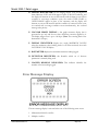
Alarm Display (SVD3)
A. DETECTOR: identifies which detector alarm settings are being
displayed
B. RATEMETER LOW ALARM: indicates the ratemeter alarm setting
C. RATEMETER LOW ALARM: indicates the low alarm setting for the
ratemeter. This alarm is used to identify a possible detector failure. When
the counts from the detector drop below the alarm set point, the alarm is
activated.
D. SCALER ALARM: indicates the scaler alarm setting
E. INTEGRATED DOSE ALARM: indicates the alarm setting for the
integrated dose counter
F. OVERLOAD: indicates the current overload current setting. When
disabled, the word OFF appears.
Logged Data Display (SVD4)
Ludlum Measurements, Inc.
Page 11
May 2015
Model 2350-1 Data Logger
A. DATA SOURCE: identifies the source of the logged data (i.e.
ratemeter, scaler, or integrated dose)
B. CLOCK: displays the current time of day in 24-hour format. If the
battery voltage reads 4.4 volts or less, the message LO BAT
alternates with the time at one-second intervals.
C. LOCATION CODES 7 & 8: identifies the preset Location Code 7
and Location Coordinate 8
D. SAMPLE NUMBER: identifies the sample number you are
viewing
E. LOCATION CODE 1 & 2: identifies the five-character
alphanumeric Location Codes 1 & 2 (These are the same codes that
appear on the normal display.)
F. DETECTOR NUMBER: identifies the detector used in the
logged sample
G. LOGGED COUNT: displays the actual count taken in exponential
format. When ratemeter count or integrated dose count is taken, the
exposure rate will display. If a scaler count is taken, the count time
will display.
H. DATE: This identifier indicates the current date.
Logged Data Location Display (SVD8)
This display provides the user with the eight different identifiers for each
location. L1-L7 are strings of five alphanumeric characters, and L8 is a
five-digit location coordinate.
A. L1: a five-character alphanumeric location identifier
Ludlum Measurements, Inc.
Page 12
May 2015
Model 2350-1 Data Logger
B. L2: a five-character alphanumeric location identifier
C. L3: a five-character alphanumeric location identifier
D. L4: a five-character alphanumeric location identifier
E. L5: a five-character alphanumeric location identifier
F. L6: a five-character alphanumeric location identifier
G. L7: a five-character alphanumeric location identifier
H. L8: a five-digit location coordinate that can have a value from 0 to
65535 (The location coordinate can be set to automatically change by
a set increment when data is logged.)
Recycle Data Display (SVD5)
A. CYCLE COUNTER: indicates the number of cycles that will be
run, the number of cycles in process, and the number of recycles
remaining
B. CYCLE DELAY: indicates the time delay between each cycle
C. CLOCK: displays the current time of day in 24-hour format
D. LOCATION CODES 1 & 2: identifies the five-character
alphanumeric Location Code Settings 1 & 2
E. DIGITAL RATEMETER: an auto-ranging display. Low and highlevel alarm indicators LOW and ALM appear in place of the RAT
indicator, and the display will alternate at one-second intervals until
the alarm is reset. When overload or over-range conditions occur, the
words OVER LOAD or OVER RANGE appear in place of the
ratemeter, and the display will alternate at one-second intervals until
Ludlum Measurements, Inc.
Page 13
May 2015
Model 2350-1 Data Logger
the condition is corrected. In the event an overload and over-range
condition occurs simultaneously, the overload message takes priority.
F. LOG BAR GRAPH DISPLAY: a bar graph ratemeter display that
is presented in cps only and does not have dead time correction
applied to it. The display ranges from 1 cps to 100 kcps. (Note: The
counting limit of the instrument is 50 kcps.)
G. SCALER: a six-digit gross counter. When a count is being taken, the
count message (CNT) is shown in place of the scaler indicator (SCL).
When the instrument is in the data logging mode, the logging
indicator (ALM) displays and the display will alternate between the
ALM and SCL indicators at one-second intervals.
H. SCALER TIMER: The scaler timer is displayed on this line. The
count time is always displayed in seconds and will do a count-down
to indicate the amount of time left in the count.
I. DETECTOR IDENTIFIER: This identifies which set of detector
parameters is currently being used.
J. LOGGED READING INDICATOR: This indicator identifies
the number of the last reading logged.
K. RECYCLE DISABLE: indicates that Recycle Mode has been
disabled. (Message replaces the Recycle Mode parameters.)
Ludlum Measurements, Inc.
Page 14
May 2015
Model 2350-1 Data Logger
Recycle Setup Display (SVD6)
A. IDENTIFIER: indicates that this is the Recycle Setup display
B. RECYCLE SETUP: displays the parameters for Cycles 1-6. When enabled,
the cycle number, detector number, delay time between recycles, and logging
mode (i.e. ratemeter, scaler, or integrated dose) are displayed.
C. RECYCLE COUNT: indicates the number of recycles that will run once
initiated
Maximum Values Display (SVD7)
A. SCALER: displays the maximum scaler count logged and the count time
used
B. CLOCK: displays the current time of day in 24-hour format
C. LOCATION CODES 1 & 2: identifies the five-character alphanumeric
Location Code Settings 1 & 2
Ludlum Measurements, Inc.
Page 15
May 2015
Model 2350-1 Data Logger
D. DIGITAL RATEMETER: an auto-ranging display. Low and high-level
alarm indicators LOW and ALM appear in place of the RAT indicator, and
the display will alternate at one-second intervals until the alarm is reset. When
overload or over-range conditions occur, the words OVER LOAD or
OVER RANGE appear in place of the ratemeter, and the display will
alternate at one-second intervals until the condition is corrected. In the event
an overload and over-range condition occurs simultaneously, the overload
message takes priority.
E. LOG BAR GRAPH DISPLAY: a bar graph ratemeter display that is
presented in cps only and does not have dead time correction applied to it.
The display ranges from 1 cps to 100 kcps. (Note: The counting limit of the
instrument is 50 kcps.)
F. DISPLAY IDENTIFIER: displays the words MAXIMUM VALUES
when the maximum values latching mode is off. When activated, the words
LATCHING VALUES display.
G. RATEMETER: displays the maximum ratemeter reading logged
H. DETECTOR IDENTIFIER: this identifies which set of detector
parameters is currently being used
I. LOGGED READING INDICATOR: This indicator identifies the
number of the last reading logged.
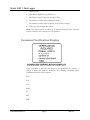
Error Message Display
The error message display is activated when one of the following errors occur:
1. Mathematical bit shift overflow
2. Multiply overflow
Ludlum Measurements, Inc.
Page 16
May 2015
Model 2350-1 Data Logger
3. Divide by zero
4. Dead time multiplied by recorded rate > 1
5. Dead time corrected count has exceeded 3 bytes
6. Accumulator overflow when adding new count
7. Accumulator overflow when correcting for new time constant
8. Counts per second larger than 4 bytes
Note: This screen cannot be called up. It appears alternately with whichever
screen is currently active until the error is corrected.
Command Verification Display
These commands require the instrument to save parameters to memory or
change or delete data required verification. The following commands require
command verification when executed:
SAA
SAC
SCA
SKD
SP
SSC
SSR
Ludlum Measurements, Inc.
Page 17
May 2015
Model 2350-1 Data Logger
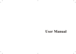
Optional Keypad Control
A. DISPLAY: 4-line by 20-character LCD display
B. FUNCTION KEYS: programmable multi-task function keys
C. KEYPAD: 40-key complete alphanumeric, soft-touch keypad
Ludlum Measurements, Inc.
Page 18
May 2015
Model 2350-1 Data Logger
5
Section
Safety Considerations and
Warning Markings
Environmental Conditions for Normal Use
Indoor and outdoor use
No maximum altitude
Temperature range of 0 to 50 °C (32 to 122 °F)
Maximum relative humidity of less than 95% (non-condensing)
Mains supply voltage range 95-250 Vac
Maximum transient voltage of 1500 Vac
Installation Category (Overvoltage Category) II (as defined by IEC 1010-1)
Pollution Degree 3 (as defined by IEC 644) (Conductive pollution or dry
nonconductive pollution that becomes conductive due to condensation to be
found in industrial environments or construction sites – harsh environments.)
Cleaning Instructions and Precautions
The Model 2350-1 may be cleaned externally with a damp cloth, using only
water as the wetting agent. Do not immerse the instrument in any liquid.
Observe the following precautions when cleaning:
1. Turn the instrument OFF.
2. Allow the instrument to sit for one minute before cleaning.
Ludlum Measurements, Inc.
Page 19
May 2015
Model 2350-1 Data Logger
Warning Markings and Symbols
Caution!
The operator or responsible body is cautioned that the protection
provided by the equipment may be impaired if the equipment is used in
a manner not specified by Ludlum Measurements, Inc.
Warning!
The operator is strongly cautioned to take the following precautions to
avoid contact with internal hazardous live parts that are accessible using
a tool:
1. Turn the instrument power OFF and disconnect the power cord.
2. Allow the instrument to sit for one minute before accessing internal
components.
The “crossed-out wheelie bin” symbol notifies the consumer that the product
is not to be mixed with unsorted municipal waste when discarding; each material
must be separated. See section 9, “Recycling,” for further information. Also
Ludlum Measurements, Inc.
Page 20
May 2015
Model 2350-1 Data Logger
6
Section
Quick Start
When the Model 2350-1 is purchased with one or more detectors, each detector
is set up, and the instrument should be ready to operate when received. The
following information explains how to set up and run the communications
software, along with some of the data-dumping features.
Loading the Model 2350-1 Communications Software
1. Insert the Model 2350-1 demo disk into drive A
2. At the C:\ type a:install a: c: and press enter.
3. Read and follow the instructions presented on the screen.
4. Highlight Programs and press enter.
5. Highlight Terminal and press enter.
6. Follow the instructions presented on the display.
Note: When the software is installed, the menu will come up automatically. The
following procedures only need to be followed after the program has been exited,
and the user wants to re-enter the program later.
Starting the Model 2350-1 Communications Software
1. At the root director, type CD\m2350-1exe\menu and press enter.
2. Type demo_v02 and press enter.
3. Highlight Programs and press enter.
4. Highlight Terminal and press enter.
5. Follow the instructions presented on the display.
Once the prompts have completed, the computer will ask if you want to view the
time-out status of the commands; answer yes or no. The instrument is now ready
to receive commands from the computer. The operating commands from the
Model 2350-1 are briefly explained in the following section starting on page 35 of
Ludlum Measurements, Inc.
Page 21
May 2015
Model 2350-1 Data Logger
this manual. For a complete description, please see the Command Descriptions
Manual.
Logging Data and Dumping to a Spreadsheet
The next example walks you through the process of logging data and dumping it
into a file that can be used in a spreadsheet program. In the following example of
the Model 2350-1, it is connected to a computer and uses the terminal emulation
software that is provided with the instrument.
1. Located the calibration certificate for your instrument and determine which
detector is designated “D0.”
2. Follow the procedures below to set up the instrument for “D0,” and then
connect the detector to the instrument.
Keystrokes
Response
SVD2 – ENTER
Changes the display to the detector
display.
D0 – ENTER
Sets detector zero as the active detector.
SVD0 – ENTER
Changes the display to the main display.
The following procedure will take a scaler count and then lot it.
Keystrokes
Response
Q1 – ENTER
Takes a scaler count and logs the count
to memory.
Repeat the above procedure until you have 10 or 15 pieces of logged data, and
then proceed to the next step.
1. Press the Esc key to leave the terminal emulator program.
2. Highlight the Download menu and press enter.
3. Highlight the Normal command and press enter.
4. Follow the instructions as displayed and the Model 2350-1 will begin
downloading the logged data as well as the detector parameters for the
detector used to take the data. The detector data will be stored in the
Det_raw sub-directory, and the logged data will be stored in the Log_raw
sub-directory and can be printed in their raw form by using the DOS print
command. A sample of each type of data is provided below.
Det_raw data
37122N21,129410,RICHARD
Ludlum Measurements, Inc.
Page 22
May 2015
Model 2350-1 Data Logger
0,100,1000,0,10,7,1,0,0.000000E+00,1.000000E+00, M44-2, PR-100000,
1.000000E+09,1000000,1.000000E+09,0.000000E+00,400,0,15
Format:
1st line-firmware #, 2350 serial #, userID
succeeding lines-HV, Threshold, Window, Window On/Off, Count Time
Read Units, Time Base, RngMult, Dead Time, Cal. Const., Det. Model #,
Det. Serial #, Rat Alm, Scaler Alm, Dose Alm, Low Count Alm, Overload
Alm, Overload On/Off, Det. Setup #
Log_raw data
37122N21,129410,RICHARD
0,ONE,1,14,90,3,41,32,15,0.000000e+00,0,0,TWO,THREE,FOUR,FIVE,SI
X,SEVEN,8888,0
1,ONE,1,14,90,3,42,38,15,0.000000e+00,0,0,TWO,THREE,FOUR,FIVE,SI
X,SEVEN,8888,0
2,ONE,1,14,90,3,43,8,15,0.000000e+00,10,1,TWO,THREE,FOUR,FIVE,SI
X,SEVEN,8888,0
Format:
1st line-firmware #, 2350 Serial #, userID
succeeding lines-sample #, location1, month, day, year, hour, minute,
second, detector #, count, scaler count time, logging mode, location2,
location3, location4, location5, location6, location7, location8, status byte
Database Formatted Log_Data.TMP
“ONETWO”,”129410”,”RICHARD”,PR-100000”,15,0,01/14/90,”03:41:32”,
0.000000e+00,0,0,0,0000000,”ONE”,”TWO”,”THREE”,”FOUR”,”FIVE”,”SIX”,”SEVEN
”,”8888”
“ONETWO”,”129410”,”RICHARD”,PR-100000”,15,1,01/14/90,”03:42:38”,
0.000000e+00,0,0,0,0000000,”ONE”,”TWO”,”THREE”,”FOUR”,”FIVE”,”SIX”,”SEVEN
”,”8888”
“ONETWO”,”129410”,”RICHARD”,PR-100000”,15,2,01/14/90,”03:43:08”,
0.000000e+00,10,1,0,0000000,”ONE”,”TWO”,”THREE”,”FOUR”,”FIVE”,”SIX”,”SEVE
N”,”8888”
Format:
location1+2, 2350 Serial #, userID, det. Serial #, det. #, sample #, date, time,
count, scaler count time, logging mode, window On/Off, scaler alarm,
location1, location2, location3, location4, location5, location6, location7,
location8
Ludlum Measurements, Inc.
Page 23
May 2015
Model 2350-1 Data Logger
7
Section
Operating Procedures
Initial Instrument Setup
Battery Installation
Ensure that the power switch is in the OFF position. Open the battery lid by
turning the thumb screw counter-clockwise one quarter of a turn.
Note: The battery compartment is accessible from the back side of the
instrument housing.
Install four D cell batteries in the compartment, making sure to align (+) and (-)
marks on the battery door with the markings on the batteries.
Note: Center post of the battery is positive (+).
Close the battery door and latch it by turning the thumbscrew one quarter of a
turn clockwise until it latches firmly. Turn the power switch on. The instrument
will perform an LCD check, causing the display to go black, then it will initiate a
memory check. Once this has been completed, the instrument will momentarily
display the current battery voltage and then the last screen that was active when
the instrument was turned off. Once this process is complete, turn the
instrument off and connect it to the optional keypad and/or bar code reader, or
connect it directly to a computer. When batteries need to be replaced, ensure
that the instrument is turned off and batteries are replaced as quickly as possible.
The parameter memory is protected by a back-up power supply for
approximately 15 minutes before data is lost.
Note:
The following three sections go through the process of setting up the
instrument with the keypad, computer, and/or bar code reader.
Ludlum Measurements, Inc.
Page 24
May 2015
Model 2350-1 Data Logger
Computer Control Setup
The Model 2350-1 is provided with a basic software package that allows the user
to control eh instrument by a computer. The software has a demonstration
program, a terminal emulator to allow for command entry, and a program to
format logged data so that it may be downloaded into a spreadsheet program.
Once the software is loaded onto the computer, the following procedures will
prepare you to control the Model 2350-1 by your computer.
Connect the computer interface cable to an available serial port on your
computer.
Connect the other end to the Model 2350-1 Data Logger.
Refer to the software user’s manual for instruction on starting the software and
follow the instructions in the program.
Note:
The terminal emulator software utilizes the same commands as the
optional terminal, which are entered the same way.
Optional Keypad Setup
Note: When keypads are purchased with instruments, the following
procedures are done at initial setup and calibration. If the keypad is
connected to the instrument and the batteries go dead, it is possible that the
keypad will have to be re-initialized. New keypads that are purchased after
the instrument will also need to be initialized.
To initialize the keypad:
1. Connect the keypad to the Model 2350-1.
2. Turn the Model 2350-1 ON.
3. Press the CNTRL, SHIFT, and F1 keys simultaneously to activate the
keypad parameter display. The following screen will appear on the
keypad display.
BAUD = 9600
F1-CHANGE PARAMETER
F2-NEXT
F3-PREVIOUS
F4-QUIT
F5-SAVE
4. Press the F2 button to scroll through the parameters until you find one
that needs to be changed.
Ludlum Measurements, Inc.
Page 25
May 2015
Model 2350-1 Data Logger
5. Press the F1 button to scroll through the parameter settings until the
correct setting appears.
6. Repeat the process until all parameters are correctly set as listed below.
7. When all parameters have been set, press the F5 button to store the new
parameters in the terminal memory.
Note: Terminal memory is non-volatile and will hold the parameters
even when the keypad is disconnected from the instrument and has no
power supply
8. The keypad will beep three times and prompt you with the question,
“ARE YOU SURE?” If you want to save the parameters as you have
selected, press F1, and the parameters will be saved and the keypad will
return to normal operating mode. If not, press F5 and the terminal will
return to normal operating mode without saving the changes.
The keypad parameters should be set as follows for proper operation
with the Model 2350-1 Data Logger:
BAUD = 9600
PARITY = IGNORE
ENABLE KEY CLICK
ENABLE CURSOR
DISABLE XON/XOFF
ENABLE ECHO
CR/LF MODE = NEWLINE
SHIFT LOCK DISABLE
VIEWING ANGLE MAX
BACKLIGHT TIMED
DATA BITS = 8
REPEAT = FAST
DISABLE KNP FUNCTION
ENABLE CURSOR BLINK
ENABLE HANDSHAKE
ESCAPE MODE = ANSI
DISABLE TEST
SCROLL ON 80
ENABLE BREAK CMND
Once the parameters are set as listed above, the instrument is ready for
operation, and the user can proceed to Section 7 for setting up the
instrument for specific applications.
Determining Instrument Plateau
The bar code reader utilizes the 3 of 9 code format. This code consists of a start
character, command characters, termination character, check sum character, and
a stop character. As an example, the symbols and code to activate the normal
display would be as follows:
Ludlum Measurements, Inc.
Page 26
May 2015
Model 2350-1 Data Logger
In this example, the “*” is the start and stop character. “SVD0” is the command
being executed. “$” is the command to execute the carriage return and lien feed,
and the “P” is the check sum character that is used to ensure that the data being
sent is correct.
The following instructions will explain how to install the bar code reader wand
and begin operation:
1. Connect the wand to the instrument by aligning the pins of the connector,
pressing down firmly, and twisting approximately a quarter of a turn
clockwise until the connector latches.
2. Turn the instrument on.
3. Hold the wand at about a 10 to 20-degree angle from vertical with the tip
touching the surface approximately one-fourth of an inch from the left side
of the bar code to be read.
4. Scan the bar cod rapidly with a uniform speed.
When the instrument recognizes the code, it will give a short beep. For first-time
users, it can sometimes be difficult to get good scans. For the most part when a
user has trouble getting the reader to work, the scanning speed is too slow.
Bar code reading can make routine procedures simple to do. In some cases,
though, the bar codes will need to be protected from surrounding elements by a
laminated covering. Below are a few things to keep in mind when laminating or
covering bar codes to protect them.
1. Make sure the laminate extends at least one-fourth of an inch from the ends
of the bar code.
2. When scanning a laminated code, make sure not to scan past the edge of the
laminate, as the reader may try to identify the edge as part of the code.
3. Extended outside applications may require an ultraviolet (UV) resistant
laminate to protect the label from fading.
Setting Operating Parameters
The following section provides examples for setting the various parameters
of the instrument. For clarification purposes, these examples all start by
activating a display where the various parameters can be viewed. System
programming allows for the operator to set individual parameters at any
time and any display. The displays are simply used as a method of
confirmation that the parameters are set correctly. In addition to the various
displays, all parameter settings can be individually displayed on a computer
screen or keypad by initiating the read commands. To initiate a read
Ludlum Measurements, Inc.
Page 27
May 2015
Model 2350-1 Data Logger
command, enter an R and then the command that you want to read, and the
current setting will be displayed.
Example: To read the current high-voltage setting:
KEYSTROKES
RESPONSE
RH – ENTER
The current setting will be displaying on
either the computer screen or keypad
display.
Setting the Time of Day
KEYSTROKES
RESPONSE
SVD0 – ENTER
The instrument will display the
main display.
ST9:25 – ENTER
Sets the instrument clock to 9:25 AM.
Setting the Date
KEYSTROKES
RESPONSE
SVD1 – ENTER
The instrument will display the
parameter display.
SD01/01/95 – ENTER
Sets the date to January 1, 1995.
Setting the Location Code
Ludlum Measurements, Inc.
KEYSTROKES
RESPONSE
SVD8 – ENTER
The instrument will display the logged
data location display.
L1BLDG1 – ENTER
Sets Location Code 1 to Building 1.
L2ROOM2 – ENTER
Sets Location Code 2 to Room 2.
L8123 – ENTER
Sets the location coordinate to Position
123.
Page 28
May 2015
Model 2350-1 Data Logger
The data location code is an eight-part identifier that allows the user to set up
seven different five-character alphanumeric codes and one five-digit coordinate
for each piece of logged data. The above example could be expanded to have
five other location identifiers of up to five characters, if desired to pinpoint the
location of a reading.
Setting the User ID
KEYSTROKES
RESPONSE
SVD1 – ENTER
The instrument will display the
parameter display.
IJOHN DOE – ENTER
Sets John Doe as the user ID.
Detector Setup
The following example will set up a Model 44-2 gamma scintillator with a serial
number PR 123456 as detector #00. The detector will display in cpm, high
voltage will be 800 volts, the threshold setting will be 100, and the window will
be off. The scaler count time will be 6 seconds, the calibration constant will be 1,
and the dead time will be set at 18 microseconds.
KEYSTROKES
RESPONSE
SVD2 – ENTER
The Model 2350-1 displays the detector
parameter screen.
Note: The Model 2350-1 will display
the detector parameters that are
currently being used by the instrument
(i.e. DET 00-15). If there are no
parameters stored in memory, the
display will show the default values of
DET 00.
Ludlum Measurements, Inc.
DO – ENTER
The instrument will display the
parameters for detector 00.
M44-2 – ENTER
The numbers 44-2 will display after
MODEL on line 2 of the display.
Page 29
May 2015
Model 2350-1 Data Logger
NPR123456 – ENTER
The numbers PR123456 will display
after serial number on line 3 of the
display.
SU7 – ENTER
Sets the display units to counts. The
display will read U=7.
SM0 – ENTER
Sets the multimeter to auto-ranging. The
display will read M=0.
SB1 – ENTER
Sets the display time base to minutes.
The display will read TB=1.
H800 – ENTER
Sets the detector high voltage to 800
volts. The display will read HV=800.
WOFF – ENTER
Turns the window off. The display will
read W=OFF.
F6 – ENTER
Sets the scaler count time to 6 seconds.
The display will read CT=6.
T100 – ENTER
Sets the threshold to 100. The display
will read T=100.
SC1 – ENTER
Sets the calibration constant to 1. The
display will read CC=1.000000e+00.
SL1.8E-5 – ENTER
Sets the dead time to 18 µs. The display
will read DT=1.799999e.05.
SP0 – ENTER
Saves the above parameters as detector
00.
Note: A verification screen will appear when this command is done. To execute
the command, answer “Y ENTER.” If you do not want to save the parameters
as DET 00, press “N ENTER” to cancel the command.
Note: When setting the dead time, the actual setting may be slightly different
than the one entered, due to rounding parameters used by the instrument.
Ludlum Measurements, Inc.
Page 30
May 2015
Model 2350-1 Data Logger
Alarm Setup
There can be a total of 16 different sets of alarm parameters. One for each set of
detector parameters:
Ludlum Measurements, Inc.
KEYSTROKES
RESPONSE
SVD3 – ENTER
The instrument will display the alarm
parameters for the detector that is
currently being used.
D0 – ENTER
The instrument will display the alarm
parameters for detector 00.
J1.0E+4 – ENTER
Sets the ratemeter alarm at 10,000 cpm.
The display will read RAT 1.00000e+04.
SVC1.0E+4 – ENTER
Sets the low ratemeter alarm at 10,000
counts. The display will read
1.00000e+06.
K1.0E+6 – ENTER
Sets the integrated dose alarm at
1,000,000 counts. The display will read
1.0000e+6.
P1.0E+6 – ENTER
Sets the integrated dose alarm at
1,000,000 counts. The display will read
1.0000e+6.
O200 – ENTER
Sets the detector overload alarm at 20
microamperes. The display will read
OVERLOAD=200.
OON – ENTER
Turns the overload alarm on.
SP0 – ENTER
Saves the above alarm parameters to
detector 00. (Please see the note on the
previous page about the verification
requirement of this command.)
Page 31
May 2015
Model 2350-1 Data Logger
Recycle Data Setup
The recycle mode can be set up with one count per cycle and be able to log a
maximum of 1000 samples, or up to six different counts per cycle with
approximately 166 cycles per count.
KEYSTROKES
RESPONSE
SVD6 – ENTER
The instrument will display the Recycle
Setup Display.
SR2 – ENTER
Enables the first two sets of count
parameters on the recycle display.
Note: Cycle #1 cannot be disabled and
will always show. When using the SR
command, any number between 1 and 6
can be used to activate that number of
counts.
SY25 – ENTER
Sets the number of recycles. The bottom
line of the display should read
# RECYCLES 25
SQ1 1 10 1 – ENTER
Sets count one of the cycle to use DET
01, with a 10-second delay between
counts, and logs a scaler count. Line one
of
the
display
will
read
1 DET 01
10 Q1
SQ2 2 25 1 – ENTER
Sets count two of the cycle to use DET
02, with a 25-second delay between
counts, and logs a scaler count. Line two
of the display will read
2 DET 02
25 Q1
Note: The delay time between the counts comes before the count is taken. In
the above example when the count is started the 10-second delay in count 1 will
occur before the count is taken. After count 1 is complete, then there will be a
25-second delay before count 2 is taken.
Ludlum Measurements, Inc.
Page 32
May 2015
Model 2350-1 Data Logger
Setting Response Time
KEYSTROKES
RESPONSE
G1 – ENTER
Sets the response time to the fast mode.
Note: The “1” after the “G” is the code
for fast response time. It can also be set
for slow response – 0, or fixed respond
time – 2.
When setting the fixed response time, the following procedures may be
followed:
KEYSTROKES
RESPONSE
G1 – ENTER
Sets the response time to the fast mode.
SXG30 – ENTER
Sets the time constant to 30 seconds.
Note: The time constant can be set at
any point from 1 and 127 seconds.
Setting the Security Code
The security code is used only when changing the access levels, or restarting the
access level and security code to their default values. To change the security
code, you must be in Access Level 1.
KEYSTROKES
RESPONSE
SAC1234 – ENTER
Sets the security code to 1234.
SAA1234 – ENTER
Sets the security code and access level to
their default settings. (SC = 0; AL = 1)
Note: The 1234 is an example of the
current security code.
Ludlum Measurements, Inc.
Page 33
May 2015
Model 2350-1 Data Logger
Setting Access Levels
The Model 2350-1 has eight different access levels for control of the instrument.
Level 1 allows for total control of the instrument, while Level 8 allows the user
to control data logging functions only. The following example will set the access
level to 3, which provides the user with some control of the instrument and
access to all of the read commands.
KEYSTROKES
RESPONSE
SAL3 0 – ENTER
The command access level is changed to
Level 3.
Note: The “0” is the default security
code. This can be changed by the user at
any time. A space must be between the
access level number and the security
code for the command to be properly
read.
To ensure that the access level has been properly changed, the following
procedure may be followed to read the current access level.
KEYSTROKES
RESPONSE
RCA – ENTER
Displays the current access level of the
instrument on the computer or keypad
display.
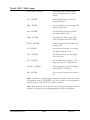
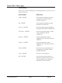
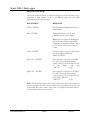
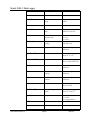
Operation Commands
There are 113 different commands that can be used to control the various
applications of the Model 2350-1 Data Logger.
A more detailed description of the commands is available in the command
reference manual. What follows is an alphabetized list of all of the commands
with a brief description of each and their adjustable parameters.
Ludlum Measurements, Inc.
Page 34
May 2015
Model 2350-1 Data Logger
Command
Description
C
Starts a scaler count
D(0-15)
Recalls a stored detector Any number between 0
setup
and 15
E
Stops a scaler count
F(1-65535)
Sets the scaler count Any number between 1
time
and 65535 seconds
G(0-2)
Sets
the
ratemeter 0 = slow
response time
1 = fast
2 = fixed
Sets the detector high Any number between 0
voltage
and 2500 volts
H(0-2500)
I(a)
Sets the user ID code
Up to 15 alphnumeric
characters
J(10-30 to 1030)
Sets the ratemeter alarm
Can be set at any point
from 10-30 to 1030
K(1-4294967295)
Sets the scaler alarm
Can be set at any point
from 1 and 4294967296
L(a)
Sets the location code
Up to 10 alphanumeric
characters
M(a)
Sets the detector model Up to 9 alphanumeric
number
characters
N(a)
Sets the detector serial Up to 9 alphanumeric
number
characters
O(0-400)
Sets the overload alarm
P(10-30 to 1030)
Sets the integrated dose Can be set at any point
alarm
from 10-30 and 1030
Q(0-2)
Logs a count
RBV
Ludlum Measurements, Inc.
Parameters
Can be set at any point
from 0 to 400
0 = ratemeter
1 = scaler
2 = integrated dose
Reads the battery voltage Will read from 0 and 6.2
Page 35
May 2015
Model 2350-1 Data Logger
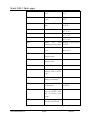
RCA
Reads the current access Displays a value from 1
level
to 8
RCB
Reads the bar graph Displays a value from 0
count
to 1e30
RCD
Reads the ID elapsed Displays a value from 0
time
to 64768
RCI
Reads the ID count
RCR
RCS
RCT
Ludlum Measurements, Inc.
Displays a value from
10-30 to 1030
Reads the ratemeter
Displays a value from
10-30 to 1030
Reads the ratemeter
Displays a value from
10-30 to 1030
Reads
the
time Displays a value from 0
remaining in scaler count to 65535
RD
Reads the detector setup Will display a number
in use
from 0 to 15
REC
Reads all detector setups
(binary format)
RED
Reads
the
detector setup
REF
Reads all detector setups
REL
Reads
the
logged
memory with L1 & L2
codes
REM
Reads
the
logged
memory (formatted)
REN
Reads the Model 2350-1 Displays a value from 0
serial number
to 999999
REO
Reads the logged data
with all location codes
and two-second time
stamp
REP
Reads the logged data
with all location codes
Page 36
current
May 2015
Model 2350-1 Data Logger
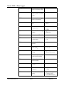
REQ
Reads
the
logged
memory in binary format
RES
Reads
the
logged
memory with L1 & L2
codes
RET
Reads
the
logged
memory (formatted)
RF
Reads the scaler count Displays a value from 0
time
to 65535
RG
Reads the ratemeter 0 = slow
response time
1 = fast
2 = fixed
Reads the detector high Displays a value from 0
voltage
to 2500 volts
RH
Ludlum Measurements, Inc.
RI
Reads the user ID code
RID
Reads the user
counter status
RIO
Reads the I/O firmware
number
RJ
Reads the
alarm setting
RK
Reads the scaler alarm Displays a value from 0
setting
to 4294967295 counts
RL
Reads
the
current
location code number
RM
Reads the detector
model number
RN
Reads the detector serial
number
RNI
Reads the
increment
RO
Reads the overload alarm Displays values x, y
setting
x = setting (0-400)
y = on/off status (0/1)
Page 37
ID 0 = off
1 = on
ratemeter Displays a value from
10e-30 to 1030
location Displays a number from
0 to 2500
May 2015
Model 2350-1 Data Logger
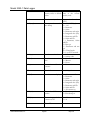
RP
Reads the ID counter Displays a value from
alarm setting
10e-30 to 10e30
RR
Reads the raw counts Displays a value from 0
from the detector
to 50000 cps
RSB
Reads the time base of 0 = seconds
the ratemeter
1 = minutes
2 = hours
Reads the calibration Displays a value from 1030
constant
to 1030
RSC
RSD
Reads the date
RSE
Reads which counters 0 = All counters off
are currently displayed
1 = Ratemeter
2 = Scaler
3 = Ratemeter and scaler
4 = Integrated dose (ID)
5 = Ratemeter and ID
6 = Scaler and ID
7 = All counters on
Reads the dead time Displays a value from
setting
10-12 to 1
RSL
RSM
RSN
RSP
RSQ(1-6)
Ludlum Measurements, Inc.
Reads the
multiplier
ratemeter 0 = Auto range
1 = micro
2 = milli
3 = None
4 = Kilo
5 = Mega
6 = Giga
7 = Tera
Reads the CP firmware
number
Reads the pushbutton 0 = Log ratemeter
logging operation
1 = Log scaler
2 = Log integrated dose
Reads the current cycle Displays values x, y, z
count
x = detector number
y = delay in seconds
z = logging mode (0-2)
0 = ratemeter
1 = scaler
2 = ID counter
Page 38
May 2015
Model 2350-1 Data Logger
RSR
Reads the number of Displays a number from
sub-cycles per recycle
1 to 6
RSS
Reads the instrument
alarm status
RST
Reads
format
RSU
Reads the
display units
RSY
Ludlum Measurements, Inc.
the
24-hour
ratemeter 0 = (r)ad
1 = (G)ray
2 = rem
3 = Sv
4=R
5 = C/kg
6=D
7=C
8 = Ci/cm2
9 = Bq/cm2
Reads the number of Displays a number from
recycles
0 to 1000
RT
Reads the detector Displays a number from
threshold setting
0 to 1000
RVC
Reads the low ratemeter Displays a value from
alarm setting
10-30 to 1030
RVM
Reads the maximum 0 = Off
values latching mode
1 = On
RVR
Reads the maximum Displays a value from
ratemeter value
10-30 to 1030
RVS
Reads the
scaler value
RW
Reads the detector Displays a value from 0
window setting
to 1000
RXG
Reads the ratemeter If the response time is set
response time
on fast or slow, the
display
reads
“VARIABLE.”
If the response time is
fixed, the display will
show a number from 1
to 127 seconds.
Page 39
maximum Displays a value from
10-30 to 1030
May 2015
Model 2350-1 Data Logger
SAA
Sets the access level and This command requires
security codes to default entry of the current
values
security code
SAC
Sets the security code
SAD(x y f)
SAL(x y)
SB(0-2)
SC(a)
SD
Sets the date
SE(1-7)
Sets the counter display
SHR(0-1)
Ludlum Measurements, Inc.
Any number from 0 to
65535
Sets up and starts the X = ON/OFF (1, 0)
auto dump
Y = 1-10
1 = Ratemeter
2 = Scaler
3 = Ratemeter and scaler
4 = Integrated dose (ID)
5 = Ratemeter and ID
6 = Scaler and ID
7 = Ratemeter, Scaler
and ID
8 = Raw cps
9 = Ratemeter and raw
cps
10 = Timed scaler
F = 1 to 65535 seconds
Sets the access level
x = 0-3
y = security code
Sets the ratemeter time 0 = Seconds
base
1 = Minutes
2 = Hours
Sets the calibration a = 10-30 to 1030
constant
mm/dd/yy format
0 = All counters off
1 = Ratemeter
2 = Scaler
3 = Ratemeter and scaler
4 = Integrated dose (ID)
5 = Ratemeter and ID
6 = Scaler and ID
7 = All counters on
Starts the HV ramp 0 = Data dump off
routine
1 = Data dump on
SID(0-1)
Turns integrated dose 0 = off
counter on/off
1 = on
SIZ
Resets ID counter
Page 40
May 2015
Model 2350-1 Data Logger
SKB
Starts CC and DT
routines
with
background subtract
SKD
Resets current detector
parameters to defaults
SL
Any number from 10-12
to 10 = off
Sets
the
ratemeter 0 = Auto range
multiplier
1 = micro
2 = milli
3 = none
4 = Kilo
5 = Mega
6 = Giga
7 = Tera
Sets the instrument serial Any number from 0 to
number
999999
SM(0-7)
SNE(x)
SNI(0-2500)
Sets the L8 location code Any number from 0 to
auto incremental value
2500
SP(0-15)
Saves a detector setup
SQ(w x y z)
Sets up a set of cycle w = cycle number (1-6)
parameters
x = detector no. (0-15)
y = delay in seconds
z = logging mode (0-2)
0 = ratemeter
1 = scaler
2 = integrated dose
Sets the number of Any number from 1 to 6
recycles per cycle
SR(1-6)
Ludlum Measurements, Inc.
Sets detector dead time
SSB
Starts
single
point
calibration routine with
background subtract
SSC
Clears
the
memory
SSD
Starts the dead time
routine with background
subtract
SSE
Stops the recycle mode
Page 41
Detector setup 0-15
logged
May 2015
Model 2350-1 Data Logger
SSF
Starts the recycle mode
SSG
Restarts a
recycle mode
SSK
Starts
calibration
constant and dead time
routines
SSP(0-2)
Sets logging pushbutton 0 = logs ratemeter
operation
1 = logs scaler
2 = logs integrated dose
Logs a count based on
SSP setup
SSQ
SSR
Resets all memory to
default values
SSS
Starts a single point
calibration routine
ST
Sets the time in 24-hour
format
SU(0-9)
Sets the ratemeter and 0 = (r)ad
integrated dose display 1 = (G)ray
units
2 = rem
3 = Sv
4=R
5 = C/kg
6 = (d)isintegrations
Sets the low ratemeter Any number from 10-30
alarm
to 1030
SVC(f)
SVD(0-7)
SVL(0-999)
SVM(0-6)
Ludlum Measurements, Inc.
stopped
Sets the instrument 0 = Main
display screen
1 = Parameters
2 = Detectors
3 = Alarms
4 = Logged data
5 = Recycle data
6 = Recycle setup
7 = Maximum values
Selects the logged data Any number from 0 to
sample to view
999
Sets
and/or
clears 0 = Latching mode off
maximum
values 1 = Latching mode on
latching mode and 2 = zeros ratemax & scalmax
Page 42
May 2015
Model 2350-1 Data Logger
displays
Ludlum Measurements, Inc.
SXG(0-127)
Sets the fixed response
SY(0-999)
Sets number of recycles
T(0-1000)
Sets the threshold
W(0-1000)
Sets the window
X
Resets the alarm
Y
Silences audible alarm
Z
Zeros the ratemeter
Page 43
3 = zeros ratemax
4 = zeros scalermax
5 = zeros scalmax & scalmax
6 = zeros ratemax & scalmax
& scal
Any number from 0 to
127 seconds
Any number from 0 to
999
Any number from 0 to
1000
Any number from 0 to
1000
May 2015
Model 2350-1 Data Logger
8
Section
Sample Applications
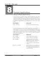
Recycle Mode Applications
The recycle mode in the Model 2350-1 is ideal for applications that require
repetitive counting processes over a grid layout, as in site decommissioning or
other related activities. The following example will demonstrate how to set up
and use the recycle mode to take an alpha survey of a site using a Ludlum Model
43-90 100 cm2 alpha scintillator. The grid is the floor of a 3 x 3 m (10 x 10 ft)
room.
KEYSTROKES
RESPONSE
SVD2 – ENTER
Sets the display to the detector display.
You can scroll through the detector setups using the D(x) command with (x) = a
number from 0 to 15. If you do not have a detector configuration already set up
for the Model 43-90, then find a blank setup (i.e. all parameters set to default
settings), and set the detector up according to the instructions on page 27 of this
manual. Once the detector is set up, save it to the active memory and proceed
with the following procedures.
Ludlum Measurements, Inc.
KEYSTROKES
RESPONSE
SSC – ENTER
Clears all logged memory registers.
SVD6 – ENTER
Displays the Recycle Setup Display.
SR1 – ENTER
Activates the first count sub-routine.
Note: The first routine is always active.
The SR1 command does, however,
ensure that only one count sub-routine
is active.
SQ1 0 15 1 – ENTER
Sets the count sub-routine parameters so
that it uses “0” for the count with a 15second delay between counts, and it will
log a scaler reading.
Page 44
May 2015
Model 2350-1 Data Logger
KEYSTROKES
RESPONSE
SY10 – ENTER
Sets the number of recycles to 10.
SVD5 – ENTER
Displays the Recycle Data Display.
SSF – ENTER
Activates the recycle routine. The
routine will start with a 15-second timeout to allow the user to position the
detector. It will then take a 10-second
scaler count and log it to the data
logging memory. It will then do another
15-second time-out to allow the user to
re-position the detector and prepare for
the next count.
The command SSE will stop a recycle routine in progress, and the command
SSG will restart a routine from the point it was stopped at.
A recycle routine can have up to six different count sub-routines performed in a
cycle. When more than one count sub-routine is performed, the logging memory
is divided by the number of sub-routines done.
Example: A recycle mode is set up with four different count sub-routines. The
maximum number of cycles that can be logged is (1000 / 4 = 2500).
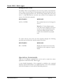
Maximum Value with Logging Pushbutton
The maximum value latching feature is useful when surveying an object, and the
user is only interested in the highest reading from the object. The instrument can
be set up with the optional pushbutton logging control in the handle and the
optional bar code reader for clearing the maximum value readings between each
count. The following description sets up the optional pushbutton and assumes
that the user is going to use a Model 44-10 5.1 x 5.1 cm (2 x 2 in.) NaI detector,
which is set up as Detector #4.
Ludlum Measurements, Inc.
KEYSTROKES
RESPONSE
SVD2 – ENTER
Displays the Detector Display.
D4 – ENTER
Places Detector #4 parameters into
active memory.
SSP0 – ENTER
Sets up the optional pushbutton so that
it will log a ratemeter reading when
pressed.
SVD7 – ENTER
Displays the Maximum Value Display.
SVM3 – ENTER
Clears the maximum ratemeter reading.
Page 45
May 2015
Model 2350-1 Data Logger
SVM1 – ENTER
Activates the latching maximum values
option.
After the above commands are completed, turn the instrument off, disconnect
the keypad or computer from the instrument, and connect the optional
pushbutton to the serial port and the bar code reader to its connector. Turn the
instrument on and connect the detector. You are now ready to survey. After each
survey, the bar code reader can be used to issue a command to clear the
maximum ratemeter reading.
Ludlum Measurements, Inc.
Page 46
May 2015
Model 2350-1 Data Logger
9
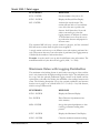
Section
Recycling
Ludlum Measurements, Inc. supports the recycling of the electronics
products it produces for the purpose of protecting the environment and to
comply with all regional, national, and international agencies that promote
economically and environmentally sustainable recycling systems. To this
end, Ludlum Measurements, Inc. strives to supply the consumer of its
goods with information regarding reuse and recycling of the many different
types of materials used in its products. With many different agencies –
public and private – involved in this pursuit, it becomes evident that a
myriad of methods can be used in the process of recycling. Therefore,
Ludlum Measurements, Inc. does not suggest one particular method over
another, but simply desires to inform its consumers of the range of
recyclable materials present in its products, so that the user will have
flexibility in following all local and federal laws.
The following types of recyclable materials are present in Ludlum
Measurements, Inc. electronics products, and should be recycled separately.
The list is not all-inclusive. Nor does it suggest that all materials are present
in each piece of equipment:
Batteries
Glass
Aluminum and Stainless Steel
Circuit Boards
Plastics
Liquid Crystal Display (LCD)
Ludlum Measurements, Inc. products, which have been placed on the market
after August 13, 2005, have been labeled with a symbol recognized
internationally as the “crossed-out wheelie bin.” This notifies the consumer that
the product is not to be mixed with unsorted municipal waste when discarding;
each material must be separated. The symbol will be placed near the AC
receptacle, except for portable equipment where it will be placed on the
battery lid.
Ludlum Measurements, Inc.
Page 47
May 2015