1
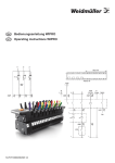
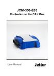
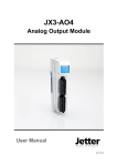
JX3-COM-PND Kommunikationsmodul Jetter AG Gräterstraße 2 D-71642 Ludwigsburg Germany Kontakte: E-Mail - Vertrieb: sales@jetter.de E-Mail - Hotline: hotline@jetter.de Telefon - Hotline: +49(0)7141/2550444 Installationsanleitung Artikel-Nr.: 60879893 | Version 1.01 August 2015 / Printed in Germany Laden Sie die Betriebsanleitung von www.jetter.de unter Support > Downloads herunter. 1x 1x 1x 10 x 1x 10000902 60870409 60870410 60870411 60879893 Lieferumfang JX3-COM-PND 2-poliger Stecker, Zugfederanschluss Kodierstifte Klemmenmarkierer Installationsanleitung Schnittstellen und Anschlüsse im Überblick Nr. Beschreibung Obere Rastlaschen LEDs des PROFINET IO Device (rechte Modulseite) 3 JX3-Backplane-Modul 4 Stecker 5 JX3-Modulgehäuse 6 X16, X17 sind Ethernet-Ports für PROFINET IO (rechte Modulseite) 7 Entriegelungslasche 8 Untere Rastlaschen (in Abbildung nicht sichtbar) 9 X10 für die Spannungsversorgung (linke Modulseite) 10 X14, X15 sind Ethernet-Ports für JetterEthernet-Systembus (linke Modulseite) 11 LEDs des Busknotens (linke Modulseite) 1 2 Montage auf Hutschiene EN 50022 Schritt 1 2 Vorgehen Setzen Sie das Modul JX3-COM-PND auf die Hutschiene oben auf. Lassen Sie das JX3-COM-PND auf der Hutschiene einrasten. Das JX3-COM-PND ist auf der Hutschiene montiert. Einstellen der IP-Adresse Schritt 1 2 Vorgehen Schalten Sie das Modul JX3-COM-PND spannungslos. Drücken Sie auf die obere und untere Rastlasche. 3 Ziehen Sie das JX3-Gehäuse des JX3-COM-PND nach vorne ab. 4 Auf dem JX3-BackplaneModul sind nun die DIP-Schalter (1) erreichbar. 1 Einstellen der IP-Adressen Schritt 5 Vorgehen Ändern Sie die IP-Adresse des Busknotens (Jetter-Ethernet-Systembus-Seite) über die DIP-Schalter (1 ... 12). IP-Adresse: 192.168.1.1 Auslieferungszustand ON 1 2 3 4 5 6 7 8 9 10 11 12 ON IP-Adresse: 192.168.10.15 Default IP-Adresse 1 2 3 4 5 6 7 8 9 10 11 12 6 7 8 Setzen Sie das JX3-Gehäuse des JX3-COM-PND wieder auf das JX3-Backplane-Modul. Versorgen Sie das JX3-COM-PND wieder mit Spannung. Stellen Sie in JetSym die Adresse des PROFINET IO Device ein. LEDs LED R E D1 D2 SYS SF BF Farbe grün Beschreibung Betriebssystem läuft Allgemeiner rot Fehler Spezielle rot Zustände Bootloader läuft rot grün-gelb System läuft (grüne LED leuchtet) Sammelfehler rot Busfehler rot LED-Zustände des JX3-COM-PND beim Einschalten Stufe 1 2 R E D1 D2 4Hz 4Hz 4Hz 4Hz 1Hz OFF OFF ON 3 1Hz OFF OFF OFF 4 1Hz ON OFF OFF 5 1Hz ON ON OFF 6 1Hz OFF OFF OFF Beschreibung Reset Der Bootloader lädt und überprüft das Betriebssystem. Das Betriebssystem liest den DIP-Schalter der Backplane und prüft das Vorhandensein des Ethernet-Switches. Das Betriebssystem initialisiert Ethernet-Schnittstelle und Dateisystem. Das Betriebssystem initialisiert den JetterEthernet-Systembus. Normaler Betriebszustand Status der LEDs des PROFINET IO Device nach erstmaligem Einschalten SYS ON SF BF ON OFF Beschreibung SYS-LED leuchtet grün. SF-LED ist aus. BF-LED ist leuchtet rot. Hinweis: Der LED-Status kann je nach Konfiguration abweichen. LED-Zustände des PROFINET IO Device LED SYS Zustand ON / 1Hz ON OFF SF OFF ON Beschreibung Die SYS-LED leuchtet grün. Das Betriebssystem läuft fehlerfrei. Die SYS-LED blinkt gelb/grün. Der Bootloader wartet auf Firmware. Die SYS-LED leuchtet gelb. Der Bootloader wartet auf Software. Die SYS-LED ist aus. Das Gerät hat keine Versorgungsspannung oder die Hardware ist defekt. Die SF-LED ist aus. Es ist kein Sammelfehler vorhanden. Die SF-LED leuchtet rot. Einer der folgenden Fehler liegt vor: Watchdog Timeout Channel-, Generische oder Erweiterte Diagnose vorhanden Systemfehler LED-Zustände des PROFINET IO Device LED Zustand 2Hz BF OFF ON 2Hz Beschreibung Die SF-LED blinkt zyklisch mit 2 Hz, 3 s lang. Ein DCP-Signal-Service wird über den Bus ausgelöst. Die BF-LED ist aus. Es ist kein Busfehler vorhanden. Die BF-LED leuchtet rot. Einer der folgenden Fehler liegt vor: Die Konfiguration fehlt Die physikalische Verbindung fehlt Die physikalische Verbindung ist zu langsam Die BF-LED blinkt zyklisch mit 2 Hz. Es ist kein Datenaustausch möglich. Anschlussbeschreibung X10 Klemmpunkt Funktion Versorgungsspannung X10.DC24V für das Modul JX3-COM-PND. X10.0V Bezugspotenzial Technische Daten X10 Spannungsbereich: Leistungsaufnahme: Potenzialtrennung: DC 24 V, -15 % ... +20 % Max. 0,27 A x 24,0 V = 6,5 W Keine Leiteranschluss X10 Technologie: Schraubendreher: AWG: Eindrähtig: Feindrähtig: Mit Aderendhülse: Aderendhülse mit Kragen: Zugfederanschluss SD 0,4 x 2,5 - DIN 5264-A 16 ... 28 H05(07) V-U 0,2 mm2 ... 1,5 mm2 H05(07) V-K 0,2 mm2 ... 1,5 mm2 0,2 mm2 ... 1,5 mm2 0,2 mm2 ... 1,0 mm2 Anschlussbeschreibung X14/X15 Teil X14 ETHERNET 1 2 3 4 X15 5 6 Funktion Buchse X14, Ethernet-Port Buchse X15, Ethernet-Port LED LINK: X14 ist mit dem Jetter-Ethernet-Systembus verbunden LED ACT: JX3-COM-PND sendet oder empfängt über X14 LED LINK: X15 ist mit dem Jetter-Ethernet-Systembus verbunden LED ACT: JX3-COM-PND sendet oder empfängt über X15 Technische Daten X14/X15 Übertragungsrate: Auto cross over: Klemmenart: Leitungsart: Schnittstelle/ Kommunikation: 10 MBit/s, 100 MBit/s Ja RJ45-Buchse Cat 5e, geschirmt Jetter-Ethernet-Systembus Anschlussbeschreibung X16/X17 Teil X16 LINK ACT 1 LINK ACT 2 3 X17 4 5 6 Funktion LED ACT: JX3-COM-PND sendet oder empfängt über X16 LED LINK: X16 ist mit PROFINET IO verbunden LED ACT: JX3-COM-PND sendet oder empfängt über X17 LED LINK: X17 ist mit PROFINET IO verbunden Buchse X16, Ethernet-Port Buchse X17, Ethernet-Port Technische Daten X16/X17 Übertragungsrate: Auto cross over: Klemmenart: Leitungsart: Schnittstelle/ Kommunikation: 100 MBit/s Ja RJ45-Buchse Cat 5e, geschirmt PROFINET IO JX3-COM-PND Communication Module Jetter AG Graeterstrasse 2 D-71642 Ludwigsburg Germany Communication: E-mail - Sales: sales@jetter.de E-mail - Hotline: hotline@jetter.de Phone - Hotline: +49(0)7141/2550444 Installation Manual Item # 60879893 | Revision 1.01 August 2015 / Printed in Germany Download the user manual from www.jetter.de, Support > Downloads. 1x 1x 1x 10 x 1x 10000902 60870409 60870410 60870411 60879893 Scope of delivery JX3-COM-PND 2-pin connector, spring-cage connection Keying pins Terminal labels Installation Manual Overview - Interfaces and connections No. Description Upper latches LEDs of the PROFINET IO Device (right hand side of the module) 3 JX3 backplane module 4 Connector 5 JX3 module enclosure 6 X16 and X17 are Ethernet ports for PROFINET IO (right hand side of the module) 7 DIN rail latch 8 Lower latches (not visible in the illustration) 9 X10 for power supply (left hand side of the module) 10 X14 and X15 are Ethernet ports for the Jetter Ethernet system bus (left hand side of the module) 11 LEDs of the bus node (left hand side of the module) 1 2 Installation on DIN rail to EN 50022 Step 1 2 Action Place the module JX3-COM-PND on the upper edge of the DIN rail. Snap the JX3-COM-PND into place on the DIN rail. Installation of the JX3-COM-PND on the DIN rail is completed. Setting the IP address Step 1 2 Action Remove power from the JX3-COM-PND. Press the upper and lower latches. 3 Pull off the JX3 enclosure of the JX3-COM-PND. 4 Now, the DIP switches (1) on the JX3 backplane module can be accessed. 1 Setting the IP address Step 5 Action Set the IP address of the bus node (on the side of the Jetter Ethernet system bus) using the DIP switches (1 ... 12). IP address: 192.168.1.1 Factory settings ON 1 2 3 4 5 6 7 8 9 10 11 12 IP address: 192.168.10.15 Default IP address Reattach the JX3 enclosure of the JX3-COM-PND to the JX3 backplane module. Restore power to the JX3-COM-PND. In JetSym, set the address of the PROFINET IO Device. ON 1 2 3 4 5 6 7 8 9 10 11 12 6 7 8 LEDs LED R E D1 Color Green Red Red D2 Red SYS SF Green/ amber Red BF Red Description OS is running Generic error Special conditions Boot loader is running System is running (green LED is lit) Accumulative error Bus error LED indications when the JX3-COM-PND is switched on Step 1 2 R E D1 D2 4Hz 4Hz 4Hz 4Hz 1Hz OFF OFF ON 3 1Hz OFF OFF OFF 4 1Hz ON OFF OFF 5 1Hz ON ON OFF 6 1Hz OFF OFF OFF Description Reset Boot loader is running and is checking the OS. The OS is reading the backplane DIP switch settings and checking if an Ethernet switch exists. The OS is initializing the Ethernet port and the file system. The OS is initializing the Jetter Ethernet system bus. Normal operating condition LED indications of the PROFINET IO Device after first power-up SYS ON SF BF ON OFF Description SYS is lit green. SF is off. BF is lit red. Note: Depending on the configuration, LED indications may vary. LED indications of the PROFINET IO Device LED SYS State ON / 1Hz ON OFF SF OFF ON 2Hz BF OFF Description SYS is lit green. The OS is running without errors. SYS is flashing amber/green. The boot loader is waiting for firmware. SYS is lit amber. The boot loader is waiting for software. SYS is off. Loss of power supply or defective hardware. SF is off. No accumulative error. SF is lit red. One of the following errors is present: Watchdog timeout Channel, generic, or extended diagnostics error System error SF is flashing at 2 Hz. Duration: 3 s. A DCP signal service has been triggered via bus. BF is off. No bus error. LED indications of the PROFINET IO Device LED State ON 2Hz Description BF is lit red. One of the following errors is present: Missing configuration Missing physical connection Physical connection is too slow. BF is flashing at 2 Hz. No data exchange possible. Connector X10 - Description Terminal point X10.DC24V X10.0V Description Power supply for module JX3-COM-PND Reference potential Connector X10 - Technical specifications Input voltage range: Power consumption: Electrical isolation: DC 24 V -15 % ... +20 % 0.27 A x 24.0 V = 6.5 W max. None Connector X10 - Wiring Technology: Screwdriver: AWG: Solid conductor: Flexible conductor: With wire end ferrule: Wire end ferrule with sleeve: Spring-cage connection SD 0.4 x 2.5 - DIN 5264-A 16 ... 28 H05(07) V-U 0.2 mm2 ... 1.5 mm2 H05(07) V-K 0.2 mm2 ... 1.5 mm2 0.2 mm2 ... 1.5 mm2 0.2 mm2 ... 1.0 mm2 X14, X15 - Description of connections ETHERNET X14 X15 Element Description 1 2 3 X14 - Ethernet port X15 - Ethernet port LED LINK: X14 is connected with the Jetter Ethernet system bus LED ACT: JX3-COM-PND is transmitting or receiving signals via X14 LED LINK: X15 is connected with the Jetter Ethernet system bus LED ACT: JX3-COM-PND is transmitting or receiving signals via X15 4 5 6 X14/X15 - Technical specifications Bit rate: Auto cross-over: Terminal type: Cable category: Interface/ communication: 10 Mbit/s, 100 Mbit/s Yes RJ45 Ethernet jack Cat 5e, shielded Jetter Ethernet system bus X16, X17 - Description of connections Element Function 1 LED ACT: JX3-COM-PND is transmitting or receiving signals via X16 LED LINK: X16 is connected with PROFINET IO LED ACT: JX3-COM-PND is transmitting or receiving signals via X17 LED LINK: X17 is connected with PROFINET IO X16 - Ethernet port X17 - Ethernet port LINK ACT X16 LINK ACT 2 X17 3 4 5 6 X16/X17 - Technical specifications Bit rate: Auto cross-over: Terminal type: Cable category: Interface/ communication: 100 MBit/s Yes RJ45 Ethernet jack Cat 5e, shielded PROFINET IO