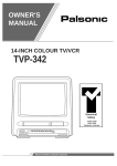
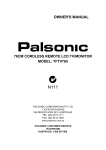
1
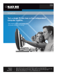
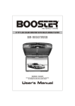
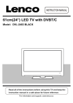
Super Video to WSXGA Converter
External Cable TV Tuner
OPERATION MANUAL
p/n CATV6
TABLE OF CONTENTS
Package Content
About The TV Tuner
…………………………………………………….………..…………. 1
……………………………………………………………………...…2
Front & Rear Panels…….………………………………………………………………….…3
Illustration of Basic Connection.…………………………………………………..……… …4
Setup Procedures….……………………………………..…………………………………5-7
Remote Controller Description………………….…………………………….………………8
Operations……………………………………………………………….………….………9-12
Specification ……………………………………………………..……………………………14
Trouble Shooting …………………………………………………………………..…………15
PACKAGE CONTENT
Before the installation, please check the package of content.
1. External Cable TV Tuner unit X 1
2. Vertical Stand X 1
3. Remote Control X 1
4. AC-DC Power Adaptor X 1
Main Unit
VGA Cable
Audio Cable
Plastic Stand
AC/DC Adaptor
1
Remote Control
ABOUT THIS VIDEO CONVERTER / TV TUNER MODULE
This external cable TV tuner unit doubles as a video upconverter and switcher. With the advanced
video processor built in, this multimedia unit delivers outstanding video quality that surpasses your
home TV display. Simply connect multiple video sources from CATV, DVD/VCR player, Camcorder,
Video Game Consoles, Satellite Receiver, Video Camera or PC together thru this unit via
AV/S-Video/VGA connections and select the desired input to watch any TV, DVD movies, computer
screen or play video games on a desktop monitor, projector or flat panel TV with sharp and clean
picture quality.
Features:
• Stand alone external NTSC TV tuner module for LCD TVs, Projection TV, LCD/CRT monitors or
projector without coax cable TV tuners built in.
• Great demodulator for converting coaxial cable TV signals into RCA video and stereo audio outputs
for TV, video recorders, A/V receivers, wireless transmitter kit, etc.
• Up-converts composite video or s-video signals into sharp progressive scan VGA signals.
• 7-level VGA output resolutions: 1680x1050, 1600x900, 1440x900 , 1280x1024, 1280x720,
1024X768 and 800x600 pixels.
• Supports PIP mode (Picture-In-Picture) for the benefit of users to watch cable TV or DVD movie
from a video sub-window while using computer at the same time.
• When in PIP mode, TV video sub-window can be resized and re-positioned to different location on
the monitor screen.
• Supports POP mode for cable TV channel preview up to 16 channels at a time in 4x4 matrix.
• Adjustable controls of video color elements for brightness, contrast, hue, saturation, color
temperature and picture modes.
• 4 video inputs(RF/Coaxial + composite video + s-video + PC VGA pass through )
• 2 video outputs( VGA + Demodulator output from coax in)
• Supports video inputs from all NTSC and PAL systems with automatic video mode detection.
• Selectable screen ratio of 4:3, 16:9 and 16:10.
• Stereo audio inputs and output.
• Supports sleep timer function for powering off the module after a pre-set time interval.
• Full-function remote controller.
Application:
• Turns any LCD monitor or projector into a LCD TV.
• Great add-on of analog cable tuner module for regular TVs, new HDTVs, Plasma flat panel,
computer monitor or projector without coax input.
• Watch DVD or VHS video on a desktop monitor.
• Converts coax analog CATV signals into composite video and audio via RCA jacks.
2
FRONT & REAR PANELS
Front Panels:
Power Button
Semi-transparent casing
Input Button
CH+/- Button
Volume+/- Button
Stereo Audio Input
Composite Video Input
S-Video Input
Rear Panels:
CABLE IN: Coax input for analog
antenna or coax CATV cable from
the wall.
Video Out:
This video converter tuner model
can also convert the coax CATV
signals and outputs in composite
RCA video signals through this port.
SPEAKER: Audio output in
3.5mm Stereo connector for
connection with multimedia
speaker or stereo system.
AUDIO IN:
VGA Pass Through: VGA
Audio input in 3.5mm Stereo
connector for connecting to the
audio output of PC sound card
input in D-sub 15-pin connector
for connection with PC. Signal
pass through only, no conversion
done on this VGA input.
MONITOR Port: VGA output
in D-sub 15-pin connector for
connection with VGA display like
CRT/ LCD/TFT monitor, projector
or LCD TV.
DC 5V: Power input connector for
AC/DC Adaptor supplied,
Please note using different rated
power supply will cause damage
to the unit.
3
ILLUSTRATION OF BASIC CONNECTION
Front View
DVD/VCD
GAMECUBE
TM
VCR
PS2
Camcorder
TM
TM
X-Box
Back View
Antenna or CATV
Audio Cable
Audio Cable
Sound Card
Speaker
VGA Card
VGA Cable
VGA Cable
Monitor or LCD
Power Adaptor
*All brand names and trademarks stated or illustrated are related to their respect owners.
4
PC Back Panel
SET UP PROCEDURE
(1.) Set up cable connection when using a LCD/CRT monitor (In this section you will
see TV pictures after finishing the installation)
a. Connect the coaxial CATV cable from the wall into the RF input (“CABLE IN” port) in the back
panel of TV tuner module.
b. Connect the VGA cable from the VGA output( “MONITOR” port) in the back panel of TV tuner
module to your VGA monitor or LCD TV monitor.
c. Run the 3.5mm audio cable from your multimedia speaker or stereo system to the audio output
(“SPEAKER” port) from the back panel of TV tuner module.
d. Connect the AC/DC power adapter of the TV tuner and power on the cable TV tuner module
using the supplied remote control or the push button on the module.
e. Set the TV tuner module at TV mode by pressing the “INPUT” button from the remote
controller or from the front control panel on the module unit itself. The “INPUT” button will
lead you to the desired video input channel from Coax(TV), Composite Video, S-Video
and PC VGA Pass Through. The video channel selection goes by a loop, i.e. CATV -> CV
-> SV -> PC -> CATV…
f. If the TV video screen is displayed on the CRT/LCD TV monitor or projector when you set the
TV tuner module at TV mode. Congratulation! You have finished the installation.
Rear
b
d.
Speaker
c.
e.
CRT or LCD
AC/DC
Adaptor
*All brand names and trademarks stated or illustrated are related to their respect owners.
5
(2)
Set up cable connection when connecting with a PC. (In this section, you will
watch TV while using your PC at the same time after finishing all the installation.)
a.
Connect the coaxial CATV cable from the wall into the RF input (“CABLE IN” port) in the
back panel of TV tuner module.
b.
Connect the VGA cable from PC video card output to the VGA input (“VGA IN” port) of TV
tuner module.
c.
Connect the VGA cable from the VGA output( “MONITOR” port) in the back panel of TV
tuner module to your VGA monitor or LCD TV monitor.
d.
Run the 3.5mm audio cable from your multimedia speaker or stereo system to the audio
output (“SPEAKER” port) from the back panel of TV tuner module.
e.
Connect the audio out from the PC sound card to the audio input (“AUDIO IN” port) in the
back panel of TV tuner module to your VGA monitor or LCD TV monitor.
f.
Connect the AC/DC power adapter of the TV tuner module and power on the cable TV
tuner module using the supplied remote control or the push button on the tuner module.
g.
Set the TV tuner module at TV mode by pressing the “INPUT” button from the remote
controller or from the front control panel on the module unit itself. The “INPUT” button will
lead you to the desired video input channel from Coax(TV), Composite Video,
S-Video and PC VGA Pass Through. The video channel selection goes by a loop, i.e.
CATV -> CV -> SV -> PC -> CATV…
h.
If the TV video screen is displayed on the CRT/LCD TV monitor or projector when you set
the TV tuner module at TV mode. Congratulation! You have finished the installation.
Rear
Sound Card
e.
VGA Card
c.
f.
*All brand names and trademarks stated or illustrated are related to their respect owners.
6
(3)
Connection with satellite receiver, set top box, video game console, DVD/VCR player or
another Video Appliances, Please use composite RCA video cable or s-video cable for
cable connection. (In this section, you can watch video showing on the screen while finishing
all the installation.)
a.
b.
c.
d.
e.
f.
g.
Follows the previous steps to connect the output from this TV tuner module to your monitor
display properly using VGA cable.
Connects the RCA video cable or s-video cable from the video output of your video source
such as satellite receiver, set top box, video game console or DVD/VCR player to the
composite video input or s-video input of the TV tuner module unit. (Please be noted that
the RCA composite cables are color-coded: yellow RCA for video, white RCA for
audio left channel and red RCA for audio right channel)
Connects the audio outputs from your video source to the RCA white and red jacks of this
TV tuner module for audio input.
Run the 3.5mm audio cable from your multimedia speaker or stereo system to the audio
output (“SPEAKER” port) from the back panel of TV tuner module.
Power on the TV tuner module.
Set the TV tuner module at the corresponding video input mode by pressing the
“INPUT” button from the remote controller or from the front control panel on the module
unit itself. The “INPUT” button will lead you to the desired video input channel from
Coax(TV), Composite Video, S-Video and PC VGA Pass Through. The video channel
selection goes by a loop, i.e. CATV -> CV -> SV -> PC -> CATV…
Play your video device now. If the picture and audio come on your monitor screen and
speaker, your installation is completed.
TM
X-Box
TM
GC
Camcorder / Video Camera
Satellite Receiver VCR/DVD
Set Top Box
PS2
TM
Media Player
All brand names and trademarks stated or illustrated are related to their respect owners.
7
REMOTE CONTROLLER DESCRIPTION
All Functions Of The IR Remote Controller
Power: Turn on/off this video
converter/TV tuner module or
used for TV <->PC mode
selection
MUTE: Press this button
to mute the audio output
from the 3.5mm mini
stereo phono jack.
Numeric Key: 0~9
PIP: Press this button to
1--: Entry for TV channel
start the TV video
sub-window at any time
over the PC Windows
screen. This function is
only active when a PC is
turned on and connected
to this video converter’s
VGA input. Users can
watch video or TV while
using the PC at the same
time by pressing this
button at any time.
number over 100. Users will
need to press this key first in
order to enter the 3-digit
channel number for higher
number TV channels.
RETURN: Last Channel
Recall (only valid in TV/CATV
mode)
MENU: Press this button to
display the setup menu on the
screen for adjustment and
configuration purpose.
INPUT: Press this
button to select the
desired video input
channel for display from
input of Coax/TV, CV,SV
or PC VGA source.
Pressing this button
repeatedly will toggle
through all different video
channel screens from
input devices connected
to this converter module.
CH+/-: TV Channel scrolling
up/down (only valid in
TV/CATV mode)
VOL+/-: Press this button to
adjust the audio output volume
RES: Press this button to
change the VGA output
resolution up to 1680x1050
pixels from this unit.
PICTURE: Press this
button for hot key for the
setting(TV function)
PREVIEW: Press this
button for TV channel preview
function
8
Using This TV Tuner For The First Time…
When the unit is powered up for the first time, the default input to the unit is TV(RF) input and there
are no TV channels available yet. Users must train the tuner by using the channel scan function
provided in the OSD operation menu to scan all the TV channels available in your area or from local
cable TV service provider. (Note: The channel scan function is available only when the input source is
set at TV mode)
Step 1: press the “MENU” button from the remote controller.
Step 2: press “CH+” or “CH-“ to scroll around all the categories until “Search” category is highlighted
and then press “VOL+” or “VOL-“ to get into the sub-menu of channel search/scan.
Step 3: In the sub-menu of channel search, there are options of “Auto Scan”, “Manual Scan” and
“TV SYS”. Move to “TV SYS” first for selection of your TV signal source. Select “CABLE” if you have
cable TV connection or select “AIR” if you have external antenna connected for analog broadcast TV
over the air.
Step 4: Next move upward to “Auto Scan” option by pressing “CH+” button from the remote.
Step 5: Once “Auto Scan” function is highlighted, press “VOL+” or VOL-“ to enter into the sub-menu.
In this sub-menu, there are options of “Fast Scan” and “Normal Scan”. User can press “CH-“ or
“CH+” button from the remote to perform either way of channel scan.
(Note: If the “Fast Scan” function could not find all the available TV channels, please change to use
“Normal Scan” function to perform the channel scan again. Normal scan function takes longer time
but with more detailed search for channel frequencies.)
Step 6: Once “Fast Scan” or “Normal Scan” is selected, press “VOL+” or “VOL-“ from the remote
control to perform the channel scan accordingly and wait for the scan process to be finished
completely.
Watching satellite video or DVD playing on your monitor
Step 1: make sure that the DVD/VCR player, satellite receiver or other video device is properly
connected to the video input of this external TV tuner module.
Step 2: press “INPUT” button on your remote controller or on the front control panel of this unit to
select composite video or s-video input channel.
Step 3: play your video device and you should see the video show up on your display.
OSD MENU OPERATION
When you press the “MENU” button on the remote control, an OSD(On-Screen-Display) menu will pop
up with 6 main category icons on the display screen as follows: “Picture”, “Search”, “Audio”, “Setup”,
“Time” and “Acces.”.
Note: All the selectable functions provided in the OSD menu can be accessed from using the
remote controller.
“MENU” button: For entering into the main menu, going back to the previous sub-menu or exiting the
menu.
“VOL+” / “VOL-“ buttons: For entering into each sub-menu, setting up parameters and selecting
function to be performed.
“CH+” / “CH-“ buttons: For moving around between the listed categories and items in the main menu
and each following sub-menu.
9
1. Picture: For Video Quality Adjustment
1.Picture
1.Bright
2.Search
2.Contrast
3.Audio
3.Saturation
4.Setup
4.Hue
5.Time
5.Color temp.
Normal /warm /cold
6.Access.
6.Picture mode
Normal/user/bright/soft
Bright: Adjust the brightness of the video output from the tuner.
Contrast: Adjust the contrast of the video output images.
Saturation: Adjust the color saturation of the video output images.
Hue: Adjust the color hue of the video output.
Color Temperature: Select the color temperature mode from Normal, Warm, and Cold modes.
Picture mode: 4 available screen picture modes up on selections (Normal/User/Bright/Soft modes).
2. Search : Available TV Channel Scan
1. Picture
2. Search
1.Auto Scan
Fast Scan
3. Audio
Normal Scan
4. Setup
5. Time
2.Manual Scan
6. Access.
Channel
1
Band
VHFL/VHFH/UHF
Search
3.TV SYS
Fine
>>>
Skip
ON/OFF
Cable/Air
Auto Scan: There are 2 methods for scanning the TV Channel.
Fast Scan: Scan and find the TV channels via channel mapping.
Normal Scan: Detailed TV channel scan by frequency step by step.
Manual Scan: This option is for analog broadcast TV use only. When users may need to scan
the channel via manual scan method, there are 5 items that you will need to do the scan.
•
Channel: You can use VOL+/- to choose the desired channel
•
Band: 3 bands of VHFL/VHFH/UHF. Use for countries with analog broadcast TV only.
•
Search: Scan for available frequency.
•
Fine: fine tune the frequency, add or decrease 0.1MHz /step
•
Skip: skip the channel
TV Sys: Select the input TV signal source from AIR Antenna or Coax Cable. If you connect this unit
to a CATV system, this option should be “CABLE”, if you connect to Free to Air Antenna you need to
set to “AIR”.
10
3 .Audio : For Audio Output Set-up And Controls
1. Picture
2. Search
3.Audio
1.volume
4. Setup
2.equalize
5.Time
3.stereo
6.Access
Volume: change the output audio volume level.
Equalize: change the balance of the audio output
Stereo: Activate stereo audio mode
4. Setup: System settings
1. Picture
2. Search
3. Audio
4.Setup
5. Time
6. Access.
1.OSD setting
Language
Bright
Mix
Background
Signal source
Colour system
2.Display mode
Monitor type
Browse mode
4:3 / 16:9 / 16:10
800*600 60/75Hz
1024*768 60/75Hz
1280*1024 60/75Hz
1280*720 60/75Hz
1440*900 60/75Hz
1600*900 60Hz
1680*1050 60Hz
Center/Bottom R
/Top R/Bottom L/Top L
4 / 9/ 16 pic.
De-noise
off/high/middle/low
Display ratio
POP mode
3.Advance
setting
English
Normal/Bright/Gloom
Normal/Heavy/Light
Gradual/Normal/Mix
TV / AV /SV
AUTO
BLE
Gamma
Display Mode
on/off
LCD / CRT /bright /off
Normal/4:3
4.Blue
background
5.Factory
mode
OSD setting: Selection of language, brightness degree, mix degree and background color for the
OSD menu display on the screen.
Display mode: Change parameter of the display mode, there are 6 items for setting.
Advance setting: Setting of the picture parameter.
11
BLUE Background: Activating screen to be blue when signal loss. There are 2 selections: ON/OFF
Factory mode: Reset all the previous setup back to the factory default settings.
Description of sub item.
Language: Fixed with English language only.
Bright: change the brightness of the OSD session.
Mix: mixture of OSD and background.
Background: Change the background style for the OSD session.
Signal Source : Change the input source. There are 3 input selections:
TV : CATV or Air TV
AV: Composite Video
SV: S-Video
Color System: Setting of the color system. The default is AUTO.
Monitor Type: Change the output aspect ratio, there are 3 selections, 4:3/16:9/16:10
Display ratio: Change the VGA output pixel resolutions at 12 different levels:
800X600
60Hz
800X600
75Hz
1024X768
60Hz
1024X768
75Hz
1280X720
60Hz
1280X720
75Hz
1280X1024 60Hz
1280X1024 75Hz
1440 X 900
60Hz
1440 x 900
1600 X 900
60Hz
1680 X 1050
75Hz
60Hz
( Note: The output resolution should be selected within the capacity of the monitor display. If you set
the output resolution of this unit beyond the maximum that your monitor can handle, there will be no
pictures showing on the screen. Use the included remote controller to power off the video converter
first and then press “0” button three times to revert the resolution back to 1024x768 pixels when the
above-mentioned did happen. )
POP-Mode: change the POP sub window position. There are 5 selections, Canter/Bottom R/Top
R/Bottom L/Top L
Browse Mode: Selection of the quick view windows number from 4, 9 to 16.
De-noise : Adjust the noise reduction level to match the best performance with your display. There are
4 selections, High, Middle, Low and Off. ( Note: If the de-noise level is set to high mode, there will be
lagging of video on some action themes so the choice should be made with caution. )
BLE: Enhance the black color level to make the video more vivid.
GAMMA: 4-Preset gamma correction level available for selection to match the performance of
different monitor type. There are 4 selections, LCD-CRT-Bright-Off
DISPLAY Mode: Change the output monitor type, there are 2 selections, Normal or 4:3
12
5 Time : Sleep Timer Setting
1. Picture
1. Sys off
00:00
no use/always/once
2. Search
2. Sys on
00:00
no use/always/once
3. Audio
3. Remind
00:00
no use/always/once
4. Setup
4. Reserve
00:00
5. Time
5. Time
00:00
6. Access.
This section is for users to configure the automation of system shutdown time or wake-up schedule.
6 .Access : Some useful software
1. Picture
2. Search
3. Audio
4. Setup
5. Time
6. Access.
Calendar
13
Product Specification
Item
Specification
CATV/TV Input
75 Ohm F female or IEC female
Frequency range
48~862MHz
Video Input
CV(Composite Video), SV(S-Video)
Audio Input (Signal Source)
Stereo RCA Left + Right Channels
Audio Input (PC)
3.5mm Stereo
VGA Input/Output Connector
D-sub HD-15 Pin Female
Power- AC/DC adaptor
5 V DC, 1A.
VGA Output Resolution
800 x 600 Pixels@ 60/75Hz
1024 x 768 Pixels@ 60/75Hz
1280 x 720 Pixels@ 60/75Hz
1280 x 1024 Pixels@ 60/75Hz
1440 x 900 Pixels@ 60/75Hz
1600 x 900 Pixels@ 60Hz
1680 x 1050 Pixels@ 60Hz
Audio Output
3.5 mm Stereo
Video Output
RCA jacket
Regulatory Compliance
FCC 15.225 FCC Part 15-Class B
ICES-003 CE, RoHS
*Specification subject to change without further notice
14
TROUBLE SHOOTING
Question : No Video ?
a.
b.
c.
d.
e.
f.
g.
h.
Please check all the cable connection first and make sure that you connect the cables
correctly between your video device, this video converter and your display unit according to
the diagram shown on page 4,5,6 and 7 in this manual.
Check the power connection and make sure that the power LED from the front panel of this
unit is turned green using the supplied power adapter from the package.
If you use a flat panel or regular TV for display, please make sure that you select the right
video input channel from your TV for screen display. Example: If the output from this video
converter/TV tuner was connected to video input #1 on the TV panel but you were expecting
and looking at video channel 2 on TV for video display, you will not see the picture from the
display because of the incorrect video channel being selected by mistake.
Make sure that you do not set the VGA output resolution of this video converter beyond the
maximum capacity that your monitor or projector can handle. Example: If your monitor
display supports up to 1280x1024 pixels but you set this video converter to output at
1600x1050 for output to the monitor, there will be no picture showing in this case and the
monitor will display an error message of “Out Of Frequency Range”. At this time please use
the remote control to power off the video converter box first and then press “0” button from
the remote three times continuously. Press the power button again, you shall see the picture
come back up again at 1024x768 pixels resolution. During this process, please do not
unplug the power adapter.
In case of compatibility issue with the VGA display you were using, you can test out this
video converter /TV tuner with a different VGA monitor or projector to find out more
information.
If you can not see TV channels from the tuner of this video converter, please do the channel
scan again as instructed on page 9. Also make sure that you select the right TV system
mode from the OSD menu of this TV tuner unit. Example : If you connect the coax cable
from the wall for CATV into the RF input of this unit, you must select TV system mode as
“CATV” from the OSD menu of this unit as stated on page 10. If you select “AIR TV “ mode,
this unit will not work correctly.
If you have digital cable TV service, you must use either a composite rca video cable or
s-video cable to connect from your digital cable box into the composite input or SV input of
this video converter. You can not connect the coax cable from your digital cable box into the
coax input of this CATV tuner. Our unit supports all the SD standard cable TV channels and
it can not decode the digital or HD channels for you. That is why you will be provided with a
digital set top box from your local cable company when you subscribe to digital cable TV
service.
If you have satellite video, you must use either a composite rca video cable or s-video cable
to connect from your satellite receiver’s output to the composite input or SV input of this
video converter as illustrated on page 7 in this manual. You can not connect the coax cable
from your satellite receiver to the coax input of this CATV. The coax input of our unit is
designed for cable TV signals only. Any other coax signals will not be decoded properly.
Question: No sound ?
a.
Please check all the audio cable connection first and make sure that you connect cables
correctly between your video device, this video converter and your display unit according to
the diagram shown in this manual.
b.
c.
Please check if your video device outputs audio properly first.
If you have accidentally muted the audio output on your video device or this video converter
15
or your display end, you will have no audio either. If that were the case, please un-mute the
audio out from your video device, video converter or display accordingly.
Question: No response from the remote controller ?
a. Make sure that you are pointing the remote controller of this video converter toward the IR
sensor window of this unit within 20 ft and +/- 15 degrees. The supplied remote control of this
unit uses infrared, not RF type like the ones used from your home TV.
b. Please check the batteries of the remote control and replace with new ones if necessary.
Question: How to reset the unit back to default ?
a. User can press the “MENU” button from the remote controller to show the configuration menu
on the screen. Then scroll to “Setup” section and select “Factory mode” to confirm reverting
all the current setting back to the default values as detailed on page 11.
16