1
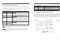
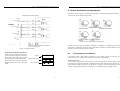
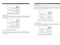
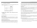
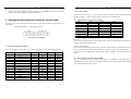
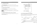
User’s Manual
For
807 8
High Performance Microstepping Driver
Version 1.0
©2000 All Rights Reserved
Attention: Please read this manual carefully before using driver!
807 8
High Performance Microstepping Driver V1.2
Table of Contents
807 8
High Performance Microstepping Driver V1.2
2. Specifications and Operating Environment
Electric Specifications (Tj = 25℃)
1. Introduction, Features and Applications ···································································2
2. Specifications and Operating Environment ······························································3
3. Driver Connectors P1 and P2 ···················································································4
4. Control Signal Connector (P1) Interface ····································································4
5. Driver Connection to Motors (P2) ············································································5
6. Power Supply and Driver Voltage and Current ···························································9
7. Selecting Microstep Resolution and Driver Current ···················································11
8. Changing Microstep Resolution on-the-fly ································································12
9. Connection Diagram for Driver, Motor, Controller ····················································13
10. Control Signal Waveform and Timing ······································································14
8078
Parameters
Min.
Peak Output Current
2.8A,/
Typical
Max.
by user
7.8A,
Supply voltage (DC)
+18V
+68V
+80V
Logic signal current
10mA
12mA
18mA
Pulse input frequency
0
By user
300Khz
Isolation resistance
500MΩ
Remark
By DIP switch
Operating Environment and Parameters
1. Introduction, Features and Applications
8078
are high performance microstepping driv ers based on most advanced technology in
the world today. They are suitable for driving any 2-phase and 4-phase hybrid step motors. By
using advanced bipolar constant-current chopping technique, they can output more speed and
power from the same motor, compared with traditional technologies such as L/R drivers. Its 3-state
current control technology allows coil currents to be well controlled, with relatively small current
ripple and results in less motor heating.
Features of this driver
High performance, low cost
Supply voltage up to +80VDC, current to 7.8A
Inaudible 20khz chopping frequency
TTL compatible and optically isolated input signals
Automatic idle-current reduction
Mixed-decay current control for less motor heating
14 selectable resolutions in decimal and binary
Microstep resolutions up to 51,200 steps/rev
Suitable for 4,6,8 lead motors
Over-current, over-voltage and short-circuit protection
Small size (119 x 97 x 48mm
Cooling
Natural cooling or forced convection
Environment
Space
Avoid dust, oil frost and corrosive gas
Temperature
0°- 50℃
Humidity
40 - 90%RH
Vibration
5.9m/s Max
Storge Temp.
2
-20℃ - +65℃
Weight
About 0.44kg
Mechanical Dimensions
Side View
Applications of this driver
Suitable for a wide range of stepping motors of size Nema 34 and 43, and usable for various kinds
of machines, such as X-Y tables, labeling machines, laser cutters, engraving machines, and
pick-place devices, particularly useful in applications with low vibration, high speed and high
precision requirements.
2
Figure 1: Mechanical dimensions
3
807 8
807 8
High Performance Microstepping Driver V1.2
3. Driver Connectors, P1 and P2
High Performance Microstepping Driver V1.2
Power connector P2 pins
The driver has two connectors, P1 for control signals, and P2 for power and motor connections.
The following is a brief description of the two connectors of the driver. More detailed descriptions
of the pins and related issues are presented in section 4, 5, 6, 9.
Control Signal Connector P1-pins
Pin No.
Signal
Functions
1
Pul﹢(+5V)
Pulse signal: in single pulse(pulse/direction) mode, this
input represents pulse signal, effective for each upward
2
Pul﹣(pulse)
– rising edge; in double pulse mode (pulse/pulse) this
input represents clockwise(CW)pulse. For reliable
response, pulse width should be longer than 3υs.
Direction signal: in single-pulse mode, this signal has
3
Dir﹢(+5V)
low/high voltage levels, representing two directions of
motor rotation; in double-pulse mode (set by inside
4
Dir﹣(Dir)
jumper JMPI), this signal is counter-clock (CCW) pulse,
effective on each rising edge. For reliable motion
response, direction signal should be sent to driver 2υs
before the first pulse of a motion direction reversal.
5
Ena+(+5V)
Enable signal: this signal is used for enable/disable, high
level for enabling driver and low level for disabling
driver. Usually left unconnected(enabled).
6
Ena- (Ena)
Pin No.
Signal
Functions
1
Gnd
DC power ground
2
+V
DC power supply, +18VDC - +80VDC, Including
voltage fluctuation and EMF voltage.
3, 4
Phase A
Motor coil A (leads A+ and A-)
5, 6
Phase B
Motor coil B (leads B+ and B-)
4. Control Signal Connector (P1) Interface
This driver uses differential inputs to increase noise immunity and interface flexibility.
Single-ended control signals from the indexer/controller can also be accepted by this interface. The
input circuit has built-in high-speed opto -coupler, and can accept signals in the format of line
driver, open-collector, or PNP output. Line driver (differential) signals are suggested for reliability.
In the following figures, connections to open-collector and PNP signals are illustrated.
Open-collector
signal (common-)
Remark 1: Pul/dir is the default mode, under-cover jumper JMP1 can be used to switch to
CW/CCW double-pulse mode.
Remark 2: Please note motion direction is also related to motor-driver wiring match.
Exchanging the connection of two wires for a coil to the driver will reverse motion
direction. (for example, reconnecting motor A+ to driver A- and motor A- to driver A+ will
invert motion direction).
4
5
807 8
807 8
High Performance Microstepping Driver V1.2
High Performance Microstepping Driver V1.2
5. Driver Connection to Step Motors
8078 driver can drive any 4, 6, 8 lead hybrid step motors. The following diagrams illustrate
connection to various kinds of motor leads:
PNP output (common anode)
Figure 3: Driver Connection to Step Motor
Note that when two coils are parallelly connected, coil inductance is reduced by half and motor
speed can be significantly increased. Serial connection will lead to increased inductance and thus
the motor can be run well only at lower speeds.
Figure 2: Signal Interface
Single Pulse and Double Pulse Modes
There is a jumper JMPI inside the driver
specifically for the purpose of selecting
Jumper
pulse signal mode. settings for one-pulse
mode (pulse/dir) and for double-pulse
double-pulse mode
mode (CW/CCW) are shown on the left.
Default mode out of factory is one pulse
one-pulse mode
Mode.
5.1
1 2 3 4 5 6
O O O O O O
Connecting to 8-Lead Motors
8 lead motors offer a high degree of flexibility to the system designer in that they may be
connected in series or parallel, thus satisfying a wide range of applications.
O O O O O O
Series Connection
A series motor configuration would typically be used in applications where a higher torque at
lower speeds is required. Because this configuration has the most inductance, the performance will
start to degrade at higher speeds. Use the per phase (or unipolar) current rating as the peak output
current, or multiply the bipolar current rating by 1.4 to determine the peak output current.
O O O O O O
6
7
807 8
High Performance Microstepping Driver V1.2
807 8
High Performance Microstepping Driver V1.2
Half Coil Configuration
As previously stated, the half coil configuration uses 50% of the motor phase windings. This gives
lower inductance, hence, lower torque output. Like the parallel connection of 8 lead motor, the
torque output will be more stable at higher speeds. This configuration is also referred to as bal
copper. In setting the driver output current multiply the specified per phase (or unipolar) current
rating by 1.4 to determine the peak output current.
Figure 4: 8 Lead Motor Series Connections
Parallel Connection
An 8 lead motor in a parallel configuration offers a more stable, but lower torque at lower speeds.
But because of the lower inductance, there will be higher torque at higher speeds. Multiply the per
phase (or unipolar) current rating by 1.96, or the bipolar current rating by 1.4, to determine the
peak output current.
Figure 6: 6 Lead Half Coil (Higher Speed) Motor Connections
Full Coil Confuguration
The full coil configuration on a six lead motor should be used in applications where higher torque
at lower speeds is desired. This configuration is also referred to as full copper. Use the per phase
(or unipolar) current rating as the peak output current.
Figure 5: 8 Lead Motor Parallel Connections
5.2
Connection to 6-Lead Motors
Like 8 lead stepping motors, 6 lead motors have two configurations available for high speed or
high torque operation. The higher speed configuration, or half coil, is so described because it uses
one half of the motor’s inductor windings. The higher torque configuration, or full coil, use the full
windings of the phases.
Figure 7: 6 Lead Full Coil (Higher Torque) Motor
8
9
807 8
5.3
High Performance Microstepping Driver V1.2
Connection to 4-Lead Motors
4 lead motors are the least flexible but easiest to wire. Speed and torque will depend on winding
inductance. In setting the driver output current, multiply the specified phase current by 1.4 to
determine the peak output current.
807 8
High Performance Microstepping Driver V1.2
used, one may use a power supply of lower current rating than that of motor (typically 50%~
70% of motor current). The reason is that the driver draws current from the power supply
capacitor of the unregulated supply only during the ON duration of the PWM cycle, but not
during OFF duration. Therefore, the average current withdrawn from power supply is
considerably less than motor current. For example, two 3A motors can be well supplied by one
power supply of 4A rating.
Multiple drivers:
It is recommended to have multiple drivers to share one power supply to reduce cost, provided
that the supply has enough capacity. To avoid cross interference, DO NOT dazy-chain the
power supply input pin of the drivers (connect them to power supply separately).
Higher supply voltage will allow higher motor speed to be achieved, at the price of more noise and
heating. If the motion speed requirement is low, it’s better to use lower supply voltage to improve
noise, heating and reliability.
NEVER connect power and ground in the wrong direction, as it will damage the driver.
6.2
Figure 8: 4 Lead Motor Connections
6. Power supply Selection, Driver Voltage and Current
Selection
6.1 Power Supply Selection
It is important to choose appropriate power supply to make the driver operate properly and
deliver optimal performance.
Maximum Voltage Input:
The power MOSFETS inside the driver can actually operate within +18V - +80VDC,
including power input fluctuation and back EMF voltage generated by motor coils during
motor shaft deceleration. Higher voltage will damage the driver. Therefore, it is suggested to
use power supplies with theoretical output voltage of no more than +95V, leaving room for
power line fluatuation and Back EMF.
Regulated or Unregulated power supply:
Both regulated and unregulated power supplies can be used to supply DC power to the driver.
However, unregulated power supplies are preferred due to their ability to withstand current
surge. If regulated power supply (such as most switching supplies.) is indeed used, it is
important to have large current output rating to avoid problems like current clamp, for example
using 4A supply for 3A motor-driver operation. On the other hand, if unregulated supply is
10
Driver Voltage and Current Selection
This driver can match small and medium size step motors (NEMA 34 and 43) made by Leadshine
or other motor manufactures from around the world. To achieve good driving results, it is
important to select supply voltage and output current properly. Generally, supply voltage
determines the high speed performance of the motor, while output current determines the output
torque of the driven motor (particularly at lower speed).
● Selecting Supply Voltage:
Higher supply voltage can increase motor torque at higher speeds, thus helpful for avoiding losing
steps. However, higher voltage may cause more motor vibration at lower speed, and it may also
cause over-voltage protection and even driver damage. Therefore, it is suggested to choose only
sufficiently high supply voltage for intended applications.
● Setting Proper Output Current
a. For a given motor, higher driver current will make the motor to output more torque, but at the
same time causes more heating in the motor and driver. Therefore, output current is generally
set to be such that the motor will not overheat for long time operation.
b.
Since parallel and serial connections of motor coils will significantly change resulting
inductance and resistance, it is therefore important to set driver output current depending on
motor phase current, motor leads and connection methods.
11
807 8
c.
High Performance Microstepping Driver V1.2
Phase current rating supplied by motor manufacturer is important to selecting driver current,
but the selection also depends on leads and connection.
807 8
High Performance Microstepping Driver V1.2
7.2 Current Setting
The first three bits (SW1, 2, 3) of the DIP switch are used to set the current during motion
(dynamic current ). Select a setting closest to your motor’s required current.
7. Selecting Microstep Resolution and Driver Current Output
DIP Setting for current during motion:
This driver uses an 8-bit DIP switch to set microstep resolution, and motor operating current, as
shown below:
Current during motion
Microstep resolution
8078
SW1
SW2
SW3
2.8A
on
on
on
3.5A
off
on
on
4.2A
on
off
on
4.9A
off
off
on
5.7A
on
on
off
6.4A
off
on
off
7.0A
on
off
off
7.8A
off
off
off
Remarks:
1) Due to motor inductance the actual current in the coil may be smaller than the dynamic current
settings, particularly at higher speeds.
7.1 Microstep Resolution Selection
Microstep resolution is set by SW5, 6, 7, 8 of the DIP switch as shown in the following table:
Microstep
ustep/rev.(for 1.8°motor)
SW5
SW6
SW7
SW8
2
400
on
on
on
on
4
800
on
off
on
on
8
1600
on
on
off
on
16
3200
on
off
off
on
off
32
6400
on
on
on
64
12800
on
off
on
off
128
25600
on
on
off
off
256
51200
on
off
off
off
5
1000
off
on
on
on
10
2000
off
off
on
on
25
5000
off
on
off
on
50
10000
off
off
off
on
125
25000
off
on
on
off
250
50000
off
off
on
off
2) Static current setting
The current automatically reduced to 60% of dynamic current setting 1 second after the last pulse.
This will, theoretically, reduce motor heating to 36% (due to I*I) of the original value. If the
application needs a different idle current, please contact Leadshine for minor modification of
circuit.
DIP setting for current during standstill:
SW4 is used for this purpose, current setting due to coil inductance. OFF meaning that the
standstill current is set to be half of the dynamic current, and ON meaning that standstill current is
set to be the same as dynamic current.
12
13
807 8
8.
High Performance Microstepping Driver V1.2
807 8
High Performance Microstepping Driver V1.2
Protection Functions
To improve reliability, the driver incorporates a number of built-in protections features.
a.
Over-voltage protection
When power supply voltage exceeds +80VDC, protection will be activated and power indicator
LED will turn red. When power supply voltage is lower than +18VDC, the driver will not works
properly.
b. Coil-ground Short Circuit Protection
Protection will be activated in case of short circuit between motor coil and ground.
c.
Over-current Protection
Protection will activated in case of short current which may otherwise damage the driver.
Attention: since there is no protection against power leads (﹢, ﹣) reversal, it is critical to
make sure that power supply leads are correctly connected to driver. Otherwise, the driver will be
damaged instantly.
Figure 9: Driver connection in a stepping system
9. Connection Diagram for Driver, Motor, Controller
A complete stepping system should include stepping motor, stepping driver, power supply and
controller (pulse generator).
A typical connection is shown below:
14
10. Control signal Waveform and Timing
This driver can accept pulse control signals up to 500khz. Before a direction reversal, direction
signal needs to be established at least 2 υs before the first pulse of the next pulse train. Please
examine time diagrams of the three control signals as follows.
15