1
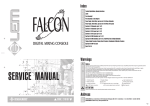
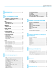
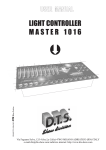
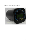
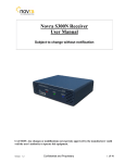
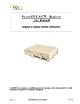
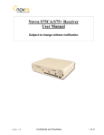
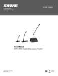
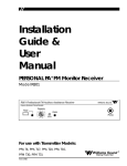
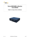
Premium 10501
05-07-00
P10501A06.DOC
User Manual Premium 10501
PHILIPS OPTICAL STORAGE
USER MANUAL
PREMIUM 10501
Philips Components
Premium 10501
05-07-00
P10501A06.DOC
draft
User Manual Premium 10501
Preface
This document gives some application information how to use the Premium 10501
The Starter kit Premium 10501 is intended to be used for high-end video/audio and Jukebox
applications. Using the kit and documentation should make it possible to provide a quickly start of the
design-in work.
The Premium 10501 is a complete functional module that consists of the CD engine, cables and
documentation. The CD engine is equipped with a PCB underneath the mechanism. The PCB contains
the electronics, and provides the necessary interface to connect the unit to the external application
circuit.
The unit can be controlled through the so-called DSA bus. Available DSA commands are described in
the Premium 10501 documentation. A floppy with DSA control software, which runs on an IBM
compatible PC, is available and is part of the documentation.
The Premium 10501 is not indented to be copied.
©Philips Electronics N.V. 2000
All rights reserved. Reproduction in whole or in part is prohibited without the written consent of the
copyright owner.
The information presented in this document does not form part of any quotation or contract, is believed
to be accurate and reliable and may be changed without notice. No liability will be accepted by the
publisher for any consequence of its use. Publication thereof does not convey nor imply any license
under patent- or other industrial or intellectual property rights.
Philips components
© 2000 Philips Electronics N.V. All rights reserved
Page 2
Premium 10501
P10501A06.DOC
05-07-00
draft
User Manual Premium 10501
PHILIPS LASER OPTICS
USER MANUAL
PREMIUM 10501
Author(s)
Phil Wu Arthur He
Philips Components
Optical Storage Shanghai
Keywords:
High-end Audio
Jukebox
DSA
CD10
VAU1254
Premium 10501
Note:
The publisher reserve the right to change the data mentioned in this document without prior notice.
Philips components
© 2000 Philips Electronics N.V. All rights reserved
Page 3
Premium 10501
05-07-00
P10501A06.DOC
draft
User Manual Premium 10501
Revision history
Version
Date
Version 0.1
draft version
05-07-00
Philips components
Remarks
© 2000 Philips Electronics N.V. All rights reserved
Page 4
Premium 10501
P10501A06.DOC
05-07-00
draft
User Manual Premium 10501
Table of Contents
1. Introduction........................................................................................................................................................... 6
1.1 Abbreviations used ........................................................................................................................................ 6
2. System overview................................................................................................................................................... 6
2.1 Features............................................................................................................................................................ 7
2.2 Some numbers ................................................................................................................................................ 7
3. PCB key component and connector placement............................................................................................... 8
4. Configuration options.......................................................................................................................................... 8
5. PCB connector interface description................................................................................................................. 9
5.1 The actuator connector (internal connection)........................................................................................... 9
5.2 The diode flex connector (internal connection)........................................................................................ 9
5.3 The DSA connector..................................................................................................................................... 10
5.4 The I2S/graphics connector....................................................................................................................... 10
5.5 The EBU connector..................................................................................................................................... 11
5.6 The power connector................................................................................................................................... 11
5.7 The line-out connector................................................................................................................................ 12
5.8 The 16 MHz clock output .......................................................................................................................... 12
6. The DSA control interface ................................................................................................................................ 12
6.1 DSA interface bus protocol........................................................................................................................ 13
6.2 DSA Commands .......................................................................................................................................... 13
6.3 Summary of DSA Control commands ..................................................................................................... 14
7. Micro Controller pinning .................................................................................................................................. 15
7.1 General........................................................................................................................................................... 15
7.2 Features.......................................................................................................................................................... 15
7.3 Micro controller Pinning............................................................................................................................. 15
8. Power requirements ........................................................................................................................................... 17
8.1 Switching the power on /off....................................................................................................................... 17
8.2 Rise time of the power supplies ................................................................................................................ 17
8.3 Ventilation..................................................................................................................................................... 17
9. Getting the best audio performance................................................................................................................. 18
9.1 Absolute audio phase.................................................................................................................................. 18
10. Connecting the Premium 10501..................................................................................................................... 19
11. Problem solving................................................................................................................................................ 20
12. General application information.................................................................................................................... 20
Philips components
© 2000 Philips Electronics N.V. All rights reserved
Page 5
Premium 10501
05-07-00
P10501A06.DOC
draft
User Manual Premium 10501
1. Introduction
Using the Premium 10501 module, the user will get a high performance CD-engine, which is designed
to deliver an extremely good playability and very low mechanical playing noise.
The module provides standard to high end audio quality output signals. For those customers who strive
for extreme high performance audio, fine tuning the audio output with additional post filtering can be
used. Using a special external DAC is still possible as the I2S signals are available.
Refer for all technical specifications to the data sheets only
1.1 Abbreviations used
BCCDAC
Bitstream Continuous Calibration Digital to Analog Converter
CD
Compact Disc
CD-DA
Compact Disc Digital Audio
CD10
SAA7324 Compact Disc Decoder & Digital Servo
DAC
Digital to Analog Converter
DSA
Data Strobe Acknowledge
EBU
European Broadcast Union
HF
High frequency (EFM) signal
LDGU
Laser Detector Grating Unit
OTP
One-time Programmable (Eprom controller).
QFP
Quad Flat Pack
VAM
Video Audio Module (CD Mechanism)
VAU
Video Audio Unit (Assembly of VAM and PCB)
2. System overview
Mechanism
PCB
HF signal
Diode
Amplifier
Laser
Supply
LF signals
TZA1022
HF Equalizer
Discrete circuit
Stereo
DAC
Digital
Servo
Control
and
CD-Decoder
TDA1305T
Left audio
Right audio
I2S
IEC958
SAA7324 M2
16MHz optional
Laser on/off
FocRa SleMo
us dialdgetor
Control
Micro
Controller
VAM1254
3-beam
Mechanism
DSA control
2x
Dual Servo
Drivers
Flash interface
TDA7073
Supply
Figure 1: Block diagram
The left part of this diagram shows the VAM1254 mechanism. The total assembly of VAM1254 and
the PCB is called the CD Engine. The Premium 10501 starterkit consist of the CD engine, some cables,
DSA interface, control software on floppy and documentation.
Philips components
© 2000 Philips Electronics N.V. All rights reserved
Page 6
Premium 10501
P10501A06.DOC
05-07-00
draft
User Manual Premium 10501
2.1 Features
•
•
•
•
•
•
•
•
The 8-bit pre-programmed micro controller provides the following functions (summary):
Execute DSA commands towards the VAM1254 mechanism and CD10 decoder.
Return subcode and status information to external controller via DSA bus.
Send sledge home at power up.
Flash new software into micro controller
The mechanism VAM1254 is three-beam mechanism with single focault focus error detection and
LDGU (Laser Detector Grating Unit) holographic pick-up.
Special S(ilent) version of digital servo controller with zero potmeters to fine-tune the application.
On board high performance Bitstream Continuous Calibration DAC with analogue stereo lineoutput.
Digital EBU output.
I2S output for connection to external DAC's or MPEG decoder
Optional 16 MHz clock output
Double (+5 and +9 V) power supply for normal operation and +12 V is needed during flash.
2.2 Some numbers
Software version:
Software ROM size:
Laser power :
HF signal amplitude:
Focus bandwidth:
Radial bandwidth:
Audio output level:
Audio output impedance:
Philips components
Version 4.x
About 32k bytes.
375 ìW.
I11 about 1.0 V pp (measured at HFIN)
1000 Hz.
1200 Hz.
1.5Veff
110 ohm
© 2000 Philips Electronics N.V. All rights reserved
Page 7
Premium 10501
05-07-00
P10501A06.DOC
draft
User Manual Premium 10501
3. PCB key component and connector placement
DSA
1
1
Driver
Audio
CD decoder + servo
DAC
1
Flash interface
1
16 Mhz (optional)
Micro P
Driver
1
1
Power IEC958
1
I2S/CDG
Figure 2: PCB component view
4. Configuration option
The PCB is prepared for the following option:
Option
16MHz output
Philips components
Function
Connector X1007 not stuffed (default)
Connector can be stuffed if 16 MHz is needed e.g. in case of Video applications
© 2000 Philips Electronics N.V. All rights reserved
Page 8
Premium 10501
05-07-00
P10501A06.DOC
draft
User Manual Premium 10501
5. PCB connector interface description
5.1 The actuator connector (internal connection)
The 6 pole Actuator connector is a Molex type 52207-0690 series connector.
PIN
Function
I/O
1
S1+
O
2
S1O
3
Home switch
I
4
GND
5
MO
6
M+
O
Table 1: Actuator connector pinning
Description
Control signal for sledge motor
Control signal for sledge motor
Home switch input
Ground for home switch
Control signal for disc motor
Control signal for disc motor
The signals SL+ and SL- form the connections to the sledge motor. The signals M+ and M- form the
connections to the turntable motor. The home switch gives the microprocessor information whether the
sledge is moved completely to the inner side. The "GND" supplies the other end of the home switch,
but as well functions as grounding wire for the ornamental plate.
5.2 The diode flex connector (internal connection)
The 16 pole flex connector is a Molex type 52207-1690 connector.
PIN
Function
1
Vsub
2
GND
3
VDD
4
RF
5
LDON
6
R2
7
R1
8
B3
9
B2
10
B1
11
FTC
12
RW
13
FOC+
14
FOC15
RAD+
16
RADTable 2: Flex connector pinning
Philips components
I/O
P
P
P
O
I
I
I
I
I
I
O
O
O
O
O
Description
+5V substrate for detector diodes
LDGU ground
Supply voltage for pre-amplifier
Not equalised HF signal
Laser on/off control H=laser on, L=laser off
Signal from detector diode (satellite diode)
Signal from detector diode (satellite diode)
Signal from detector diode (central hf diode)
Signal from detector diode (central hf/focus diode)
Signal from detector diode (central hf/focus diode)
NOT USED
Control of CD-DA and CD-RW
Control signal for focus actuator
Control signal for focus actuator
Control signal for radial actuator
Control signal for radial actuator
© 2000 Philips Electronics N.V. All rights reserved
Page 9
Premium 10501
05-07-00
P10501A06.DOC
draft
User Manual Premium 10501
5.3 The DSA connector
The 6 pole DSA connector is a JST PH series connector.
PIN
Function
1
ACK
2
DDA
3
DST
4
DRST
5
GND
6
LASER-OFF!
Table 3: DSA connector pinning
I/O
I/O
I/O
I/O
I
O
I
Description
Acknowledge
Data
Strobe
Reset
Ground
Control input for laser H=laser on, L=laser off
When controlling the Premium 10501 with an external PC, the reset line is unused.
Note that when the reset line is pulled high, this will reset the servo processor. CAUTION: Do not
connect the external reset line to ground directly. This will prevent the microprocessor from being reset
properly at power-up!
The 6th pin is added for safety requirements. The user can connect this pin to a "doorswitch" such that
whenever a user opens the lid of the cabinet, this will switch off the laser power. A "low" on this pin
will switch off the laser power. When not connecting this pin, it will float high. It is recommended
when using long external wiring to the laser_off pin to put a small 100 nF capacitor over the laser_off
input to prevent noisy glitches to switch off the jukebox module.
The mating (female) connector is an assembly of a JST type PHR-6 housing with 6 contacts type SPH002T-P0.5S. Recommended wire is type AWG24.
5.4 The I2S/graphics connector
The I2S/Graphics connector is a JST PH series connector. This is a 6 pole connector.
PIN
Function
1
MISC
2
SCLK
3
WCLK
4
DATA
5
GND
6
V4 (serial CDG output)
Table 4: Connector pinning
I/O
O
O
O
O
O
O
Description
C2 error flag
Serial clock
Word clock (word select)
Data
Ground
Serial CD Graphics output
When using the engine as a standard CD-DA module, without the MPEG option, an external DAC PCB
may be connected to this connector. This external DAC will only use the WCLK, SCLK, DATA and
ground lines of this connector. Note that for this application, the module has to be programmed for
audio mode via the DSA interface. Data will come out via the I2S connector in the I2S (default) or
EIAJ (programmable via DSA command) format.
Figure 3: I2S output timing.
Remark: The I2S output timing depends on the settings by software, see DSA commands.
The MISC/error pin is a multi-purpose pin. When the module is in "audio mode", this pin will supply a
clock at double the speed of the WCLK clock. In CD-ROM mode however, this "MISC/error" pin will
Philips components
© 2000 Philips Electronics N.V. All rights reserved
Page 10
Premium 10501
05-07-00
P10501A06.DOC
draft
User Manual Premium 10501
signal uncorrectables to the MPEG board. A logic "1" means that data output by the data interface is
incorrect. A logic "0" means data is OK.
Also an external CD-graphics decoder may be connected to this interface for karaoke applications. The
external CD-G decoder uses both the I2S signals as well as the V4 connector pin. The V4 pin provides
the QRSTUVW (Q-W channel) subcode flags in a serial way. The R-W flags can be used by the CD-G
decoder. A group of 96*6 bits forms one CD-G block.
The MISC pin is, or can be, used when the output of the Premium 10501 should be connected to a CDROM decoder or MPEG decoder. For audio applications this pin is not used.
The mating (female) connector is an assembly of a JST type PHR-6 housing with 6 contacts type SPH002T-P0.5S. Recommended wire is type AWG24.
5.5 The EBU connector
The EBU connector is a JST PH series connector. This is a 2 pole connector.
PIN
Function
1
Dig-GND
2
EBU dig data (IEC958)
Table 5: EBU connector pinning
I/O
O
O
Description
Ground
EBU output according IEC958 standard
Equipment using an EBU interface, or measurement equipment may be connected to this interface.
This interface uses an unbalanced line (two-wire transmission) as described in the IEC standard. The
interconnecting cable should be screened and have a characteristic impedance of 75 at 2.8224 MHz.
The signal amplitude should be 0.5V +/-20% peak-to-peak, when measured across a 75 ohm resistor
connected to the output terminal, without any interconnecting cable present. Rise and fall times are in
the order of 10 ns (under the same conditions).
The mating (female) connector is an assembly of a JST type PHR-2 housing with 2 contacts type SPH002T-P0.5S.
5.6 The power connector
The 4 pole power connector is a JST PH series connector.
PIN
Function
1
GND
2
+9 V supply
3
GND
4
+ 5 V supply
Table 6: Power connector pinning
I/O
I
I
I
I
Description
Ground pin 9V (not connected on PCB to ground pin 5V)!
9 volt supply for motor and actuator drivers TDA7073
Ground pin 5V (not connected on PCB to ground pin 9V)!
5 volt supply
Pin 1 and 2 function as a supply for the actuator drivers (+9V). Pin 3 and 4 supply the rest of the
circuitry (+5V). The GND connection must be connected together at the supply side to prevent
unwanted disturbance signals.
The mating (female) connector is an assembly of a JST type PHR-4 housing with 4 contacts type SPH002T-P0.5S. Recommended wire is type AWG24.
Philips components
© 2000 Philips Electronics N.V. All rights reserved
Page 11
Premium 10501
05-07-00
P10501A06.DOC
draft
User Manual Premium 10501
5.7 The line-out connector
The 4 pole line-out connector is a JST PH series connector.
PIN
Function
I/O
1
Right audio
O
2
A-GND
O
3
A-GND
O
4
Left audio
O
Table 7: Line-out connector pinning
Description
Audio output right channel
Ground
Ground
Audio output left channel
The mating (female) connector is an assembly of a JST type PHR-4 housing with 4 contacts type SPH002T-P0.5S. Recommended wire is type AWG24.
5.8 The 16 MHz clock output
The 3 pole clock output connector is a JST PH series connector. This connector is optional and not
stuffed on the PCB.
PIN
Function
I/O
1
Dig-GND
O
2
CLK16
O
3
Dig-GND
O
Table 8: Clock-out connector pinning
Description
Ground
16.9344 MHz clock output
Ground
This clock output provides a 16.9344 Mhz clock which can be used by MPEG boards which require a
clock synchronous with the CD decoder.
5.9 Flash interface
The 5 pole flash interface connector is a JST PH series connector.
PIN
Function
I/O
1
+12 V
I
2
PSEN
I
3
RXD
I
4
TXD
O
5
GND
I
Table 8: Flash interface connector pinning
Description
Power supply for programming
Program store enable
Receiver line in serial port
Transmitter line in serial port
Ground
The mating (female) connector is an assembly of a JST type PHR-5 housing with 5 contacts type SPH002T-P0.5S. Recommended wire is type AWG24.
6. The DSA control interface
The DSA (Data Strobe Acknowledge) interface is a serial interface used for communication between 2
processors. One processor is located on the CD engine PCB, the other one might be an external
processor on another PCB or a PC computer.
In this paper we call the external processor the "host".
Communication between host and CD engine uses a 16 bit structure. The 16 bits contain a
COMMAND byte followed by a DATA byte, transmitted in one string. Transmission is done with the
MSB first. Both processors can send commands to the other. The CD-engine for example can send time
information to the host.
Philips components
© 2000 Philips Electronics N.V. All rights reserved
Page 12
Premium 10501
05-07-00
P10501A06.DOC
draft
User Manual Premium 10501
6.1 DSA interface bus protocol
Each data communication consists of three phases:
• Synchronisation phase.
• Data transmission.
• Acknowledge phase.
A full description of the protocol is documented in a separate manual in the premium 10501 starterkit
documentation.
6.2 DSA Commands
The commands understood by the servo processor on the CD engine are documented in a separate
manual in the Premium 10501 DSA documentation. The table in next chapter gives an indication of the
commands to be expected.
The servo processor on the CD engine does not only receive commands, it will give back information
as well. The information to be output by the servo processor can be programmed by putting the servo
processor in a different mode. For instance, there is a mode, such that the servo processor gives no
information back at all, or another mode, where the processor gives back subcode information, and so
on. Attached at the end of this document, some examples are given.
Philips components
© 2000 Philips Electronics N.V. All rights reserved
Page 13
Premium 10501
05-07-00
P10501A06.DOC
draft
User Manual Premium 10501
6.3 Summary of DSA Control commands
The commands are divided into the following groups:
• Control commands
• Info retrieve commands
• Mode setting commands
• Service commands
A full description of the commands is given the Premium 10501 starterkit documentation.
Command name
Play title
Stop
Read TOC
Read long TOC
Clear TOC
Pause
Pause release
Goto time
Spin up
Play A till B time
Function
Play title number nn and respond with specified info according Set Mode
Stop playing, sledge move to the home position, disc is stopped
Reads the TOC of the specified session and sends info to the user processor
Reads the complete TOC and sends info to user processor
Clear the TOC stored in RAM
Stop playing the disc, present sledge position is maintained
Continue playing the disc at present sledge position
Jump to the absolute requested time location on disc and respond with found
Spin up the disc at the specified session and respond with found
Play from absolute requested time A till absolute time B
Summary Info retrieve commands
Command name
Function
Get tittle length
Send the time of the specified title to the user processor
Get complete time
Send the absolute disc time to the user processor
Get last error
Send the last encountered error to the user processor
Get disc status
Send the current disc status
Get session info
Send the number of finalised sessions on the disc
Summary of Mode setting commands
Command name
Function
Set Mode
Mode setting for speed, TOC info, and activates the AUDIO or ROM mode
Clear error
Clear the latest error code
Release A->B time
Releases the A till B time feature
Set volume
Set the volume level (only in audio mode) from 0 till 255 (full scale)
Set DAC mode
Set I2S output format and error correction for AUDIO
Summary of Service commands
Command name
Function
Service mode on
Switches the service mode on and gives the servo version number
Service mode off
Switches the service mode off and gives the servo version number
Sledge jump
Make a sledge jump of 300 ms
Sledge off
Switches the sledge movement off and go to the inner position
Focus on
Switches the focus on
Focus off
Switches the focus off
Turntable motor on
Switches the turntable motor on
Turntable motor off
Switches the turntable motor off
Radial on
Switches the radial control loop on
Radial off
Switches the radial control loop off
Laser on
Switches the laser on
Laser off
Switched the laser off
Philips components
© 2000 Philips Electronics N.V. All rights reserved
Page 14
Premium 10501
05-07-00
P10501A06.DOC
draft
User Manual Premium 10501
7. Micro Controller pinning
Remark:
Micro controller pinning given in this chapter, is for information only and can be used in case of
debugging. No guarantee can be given that NC (Non Connected) pins will not be assigned in future
software versions.
7.1 General
The micro controller is specially designed for the high-end CD engine, to control the mechanism and
CD10, and is based on the generic P89C51xx+ CMOS single-chip micro controller with internal 64K*8
ROM.
Device name:
Function:
Package:
P89C51RC+/ P89C51RD+
High-end Audio and Video CD applications with VAM1254 and CD10
44 pin QFP
7.2 Features
•
•
•
•
•
Controls the CD10 decoder/servo IC
Translate the high level DSA commands to low level CD-player commands
Provides subcode/time information and player status information
Use the DSA bus protocol as communication to an external processor
Flash new software into micro controller
7.3 Micro controller Pinning
Pin
1
2
3
4
5
6
7
8
9
10
11
12
13
14
15
16
17
18
19
20
21
22
23
24
25
27
Micro controller (P89C51RC+/P89C51RD+)
Package: QFP44
Name
I/O
Function
P1.5
DSA-DATA
I/O
DSA data
P1.6
DSA-STR
I/O
DSA strobe
P1.7
NC
RST
DSA-RST
I
HIGH: Microcontroller is in reset mode
P3.0/RxD
RXD
I
Serial port receiver
NC1
P3.1 /TxD
TXD
O
Serial port transmitter
P3.2/INT0!
Laser on
O
Laser power on-off control
HIGH = laser on, LOW = laser off
P3.3/INT1!
NC
P3.4
NC
P3.5
NC
P3.6
NC
P3.7
NC
XTAL2
O
Crystal Oscillator.
XTAL1
I
Crystal Oscillator (12 MHz)
GND
Ground
NC2
P2.0
DMSB
O
Audio enable of double speed input for DAC
P2.1
NC
P2.2
NC
P2.3
RW
NC
Control of CD-DA and CD-RW
P2.4
HOMESW!
I
LOW: Sledge of VAM1254 mechanism is in home
position
P2.5
NC
P2.6
NC
P2.7
F250
I
Factory design
ALE/PROG!
NC
Address Latch Enable.
Philips components
© 2000 Philips Electronics N.V. All rights reserved
Page 15
Premium 10501
05-07-00
P10501A06.DOC
draft
User Manual Premium 10501
This micro controller does not use any external RAM or
ROM. This pin should be left unconnected.
28
29
30
31
32
33
34
35
36
37
38
39
40
41
42
43
44
NC3
I
EA!/ Vpp
P0.7/AD7
P0.6/AD6
P0.5/AD5
P0.4/AD4
P0.3/AD3
P0.2/AD2
P0.1/AD1
P0.0/AD0
VCC
S2
S1
P1.0
P1.1
P1.2
P1.3
P1.4
DSA-ACK
Philips components
Reset
Mute
On_track
HFDET
SDA
SILD
SCL
O
O
NC
O
O
O
NC
I
NC4
I/O
NC
I/O
O
O
Not External Address. This pin should be held high to
ensure that the microcontroller uses internal program
memory only. +12V during flash.
Switching control for equaliser & filter
Switching control for equaliser & filter
Reset for CD10 SAA7324
Mute signal for DAC
Factory design
HF detector
+5V supply
DSA acknowledgement
Serial data for communication with CD10
R/W control and data strobe to CD10
Serial bit clock for communication to CD10
© 2000 Philips Electronics N.V. All rights reserved
Page 16
Premium 10501
05-07-00
P10501A06.DOC
draft
User Manual Premium 10501
8. Power requirements
The CD Engine PCB requires 2 external power supplies. This section shows the required supply levels
and currents.
Stop mode
+5V
120 mA
+9V
40 mA
Table 10: Power requirements
Spin up/down & jump
180 mA
600 mA
Normal play
190 mA
120 mA
The peak current of 600 mA for the +9V supply will be during spin up or down of the disc. This will
take about 1-2 seconds, then the power consumption will drop to the average normal play value.
8.1 Switching the power on /off
Between switching off the power of the module and switching it back on again, the user should wait 1
sec. (Just like in any other audio application). This to make sure that the microprocessor is properly
reset during power up. The max. RESET TIME is 1 sec. after the 5 V has been switched on. After this
time, commands (e.g. SPIN_UP) may be sent. If the sledge is - on this moment - not yet at the inner
position, the command will be executed on the moment the sledge is home!
If the user wants to avoid improper reset of the microprocessor on successive power on/power-off
cycling without waits, an external reset pulse can be given to the microprocessor via the DSA interface,
to guarantee that the microprocessor is reset.
8.2 Rise time of the power supplies
If the +9V power comes up faster than the +5V, the user may notice spurious movements of the
actuator upon power up. This is because in this situation, the drivers are powered up first by the +9V
supply, then after the drivers are powered up, the +5V is still rising. Now the driver will follow the
power up pattern of the +5V and put this waveform in an amplified way on the actuators. This will
cause movement of the actuators. If the +5V and +9V have the same rise time, the actuator movement
is reasonable. If the user does not allow any movement at all, the +5V supply should come up a little
faster ( 150 msec) than the +9V supply, at start-up. 150 msec is enough here, increasing this figure is
not necessary for normal supplies. Only when the rise time of the +5V is very slow, the 150 msec have
to be increased.
The same for switching of the power supply, only now it's the other way round:
When switching off the power supply, the +9V should be switched off first.
When switching the power on or off a "very low level" click may be heard through the audio output.
When using amplifiers with proper speaker protection during power up/down, this will cause no
trouble.
8.3 Ventilation
The +9 V terminal can be connected to a power supply level between 8.1 and 10.35V. It is possible to
operate it with higher supply levels, but this extra power will only be translated into extra heat which in
turn will decrease the lifetime of the product, so it is recommended to operate it at supply levels
between 8.1 and 10.35V. When operating the CD engine inside a closed cabinet on supply levels higher
then 10.35V, the temperature of the module will substantially rise, thus warming up the laser. This will
reduce the lifetime of the module. Therefore, when using higher supply levels, it is recommended to
provide some ventilation holes (or a fan) inside the cabinet in the neighbourhood of the two
TDA7073AT drivers. These two IC's can get very hot during operation, especially during spin up or
down and accessing a new song on the disc.
Philips components
© 2000 Philips Electronics N.V. All rights reserved
Page 17
Premium 10501
P10501A06.DOC
05-07-00
draft
User Manual Premium 10501
9. Getting the best audio performance
The usual audio software on CD-DA discs has a SNR of 98dB max. The output of CD10 is already deemphasised, and then again quantized to 16 bits again. This means at this stage, the theoretical max.
attainable SNR which can be get from the BCCDAC2 will be 98dB. Measured operational values are
about 97dB. THD at 0dB input signal will be -85dB, at -60dB input signal will be -35 dB.
For the best audio performance, the power supply wires should be type AWG24 wire. The PCB
should be connected to 2 independent power supplies. One for the +5V, the other for the +9V.
The ground terminals of the two power supplies must be connected at the supply side to reduce voltage
drop or ripple over the power wiring. The ground terminals of the supply connector are not connected
on the PCB!!!
9.1 Absolute audio phase
One of the properties of the BCCDAC2 is that the phase of the audio output has turned 180 degree.
For those customers who want to feature absolute phase in their design, an inverting amplifier should
be used between premium module and speaker/headphone output.
Philips components
© 2000 Philips Electronics N.V. All rights reserved
Page 18
Premium 10501
05-07-00
P10501A06.DOC
draft
User Manual Premium 10501
10. Connecting the Premium 10501
DSA
interface
To PC
Audio out
DSA
1
Audio
To PC
1
RS 232
FLASH Interface Pcb
Driver
CD decoder + servo
DAC
1
Flash interface
1
16 Mhz (optional)
MicroP
Driver
1
1
1
Power IEC958
+5 /+ 12V
External
Power
Supply
I2S/CDG
_
+ 9 V Power Supply
+
_
+ 5 V Power Supply
+
Figure 4: Connecting the Premium 10501.
Remark:
The grounds (-) of the +5V and +9V must be interconnected at the power supply side. These grounds
are not interconnected at the PCB side!!
Philips components
© 2000 Philips Electronics N.V. All rights reserved
Page 19
Premium 10501
05-07-00
P10501A06.DOC
draft
User Manual Premium 10501
11. Problem solving.
Some tips on servicing the Premium 10501, when the set does not work correctly.
•
At start-up the sledge does not move home, but the actuator starts ramping.
Probably the servo microprocessor is not running. Check microprocessor oscillator.
•
At start-up, the sledge moves wildly in both directions.
Homeswitch short circuit to ground.
•
Set gets into focus, but does not start spindle motor.
Check pin 26 of CD10. If there's a clock there, there must be something wrong in the spindle
motor driver stage. If there is no clock at pin 26 of CD10, check the oscillator christal
circuit of CD10.
•
At start-up the sledge moves home and then starts rattling.
The homeswitch wiring probably interrupted or dirty contacts of homeswitch.
•
At start-up the sledge moves home, then the set does not do anything at all.
Probably something wrong with the DSA wiring.
•
CDM does not ramp to catch focus. Software gives message "FOCUS ERROR/ NO DISC".
Check voltage across the safety resistor 3208
12. General application information
The application covers the high end-audio, Video and Jukebox applications
•
Speed n =1
•
Speed n = 2 (optional), design is functional prepared but not released.
Position of operation:
•
Horizontal is recommended
•
Vertical is allowed with preferred side A or B down, see VAM1254 data sheet
Safety:
• Special measures have been taken for safety reasons:
1. A laser off input is implemented
2. Safety resistors (NFR) have been applied
The Set maker is responsible for safety of the total application including the CD engine used
in this application
•
Radiation: Not valid, to be specified by the set maker
Although the setmaker is responsible, measures have been taken to reduce radiation by using
double sided PCB and SMD technology.
Shielding: If a metal shielding is used with a distance of less then 5 mm to the PCB, the shielding has
to be connected to the PCB ground.
Philips components
© 2000 Philips Electronics N.V. All rights reserved
Page 20