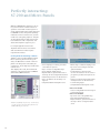
1
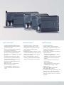
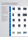
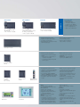
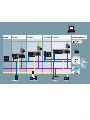
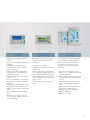
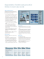
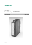
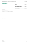
SIMATIC S7-200
Control technology a class of its own
SIMATIC Controller
Answers for industry.
Communicative, modular, compact:
So small – and so powerful
The Micro PLC SIMATIC S7-200 is truly in
a class of its own: it’s both compact and
highly powerful – especially in relation to
its real-time response – it’s fast, features
great communications options and comes
with really easy-to-operate software and
hardware.
But there’s more to it than that: the Micro
PLC SIMATIC S7-200 has a consistently
modular design – for customized solutions which aren’t too large for the
present but open-ended enough to be
expanded anytime in the future.
All this makes the SIMATIC S7-200 a real
economic alternative in open-loop control for the lower performance range. For
any applications in automation engineering that constantly depend on innovation
and optimum customer benefit.
2
SIMATIC S7-200 delivers consistently
economical solutions. The entire
system family features
• powerful performance,
• optimum modularity and
• open communications.
In addition, the SIMATIC S7-200 programming tool makes your job even easier: the
Micro PLC is very easy to program allowing fast and easy realization of applications – and the add-on libraries for the
software accelerate and facilitate your
work even more.
This Micro PLC has been in successful use
in millions of applications around the
world – in both stand-alone solutions and
networks.
Find out for yourself what the
SIMATIC S7-200 has to offer!
Open communication
Powerful performance
Optimal modularity
• Integrated standard RS 485 interface
with data transmission rates between
1.2 and 187.5 kbit/s
• PPI protocol functioning as system bus
for trouble-free networking
• Programmable mode with user-specific
protocols for any peripheral devices
• Fast connection to PROFIBUS via module
as a slave
• Powerful to AS-Interface as a master
• Communications anywhere thanks to
modem link (for remote maintenance,
teleservice or telecontrol)
• Connection to Industrial Ethernet via
Ethernet module
• With connection to the Internet by
means of Internet module
• S7-200 PC ACCESS – OPC Server for
simple connection to the PC environment
• Small and compact – ideal for any
applications where space is tight
• Integrated and comprehensive basic
functionality in all CPU models
• Large memory
• Outstanding real-time response – being
in total command of the entire process
at any time means increased quality,
efficiency and safety
• Easy to handle thanks to the userfriendly software STEP 7-Micro/WIN –
ideal for both beginners and experts
• Systems engineering:
• 5 distinct CPUs in the performance
range with comprehensive basic functionality and integrated Freeport communications interface
• A wide range of expansion modules for
various functions:
– Digital/analog expansions, scalable
to specific requirements
– PROFIBUS communications as a slave
– AS-Interface communications as a
master
– Exact temperature measurement
– Positioning
– Remote diagnostics
– Ethernet/Internet communications
– SIWAREX MS weighing module
• HMI functions
• STEP 7-Micro/WIN software with
Micro/WIN add-on library
• Compelling systems engineering – now
featuring precise dimensioning and
optimum solutions for a wide range of
different requirements for one automation task
3
Fast, intelligent and well-planned:
A system of endless possibilities
CPU 224
6/4 inputs/outputs
8/6 inputs/outputs (I/O)
+ max. 2 modules = 78 I/Os
14/10 inputs/outputs (I/O)
+ max. 7 modules = 168 I/Os
Input modules
Output modules
Digital and analog
expansions
CPUs
CPU 222
Input/output modules
RTD temperature
measurement
TC temperature
measurement
SIWAREX MS
weighing module
AS-Interface master
CP 243-2
max. 2 modules
PROFIBUS DP slave
EM 277
Ethernet module
CP 243-1
max. 1 module
Operating and
monitoring
Communication
Highlights
• Memory card for data logging,
recipe management, saving of
Micro/WIN project, storage of
documentation in various formats
• PID auto-tune function
• 2 interfaces onboard for extended
communication options, e.g. with
other manufacturers’ devices
(CPU 224 XP, CPU 226)
• CPU 224 XP with integral analog
inputs/outputs
CPU 221
Specific
expansions
Tried and tested worldwide thanks to:
• Compact design
• High basic functionality
• Modular expansion options
• Integral RS 485 interface for
use as system bus
• Excellent real-time behavior
• Extremely fast and precise process
and sequence control
• Seamless control of time-critical
processes by means of time interrupts
• Simple and user-friendly connection method thanks to removable
terminal strips on the CPU and
expansion modules – permanent
wiring
TD 100C
4
TD 200/TD 200C
TD 400C
CPU 224XPsi
CPU 226
14/10 inputs/outputs (I/O)
2/1 analog I/O
+ max. 7 modules = 168 I/Os
14/10 inputs/outputs
(current-sinking digital outputs)
2/1 analog inputs/outputs
+ max. 7 modules = 224 I/Os
24/16 inputs/outputs (I/O)
+ max. 7 modules = 248 I/Os
Software
CPU 224XP
STEP 7-Micro/WIN
• Easy handling
• Windows standard
• Configuration instead of
programming: the Wizards
• Powerful instruction set easy
to use via drag-and-drop
• Status for STL, LAD and CSF
• Modular buildingblock system
• Expansion modules can be scaled
according to requirements
• Digital expansion modules from 4/4 to
32/32 inputs/outputs
• Analog expansion modules from 4/0,
4/1 to 0/2 inputs/outputs
• Power modules for switching
loads: 5-A-DC or 10-A relay
• Modules for exact temperature
measurement to a tenth of a degree
Celsius:
– RTD module for measurement of
resistance temperature
– TC module for measurements with
thermocouples
• EM 253 positioning module for
controlling stepper motors and
servodrives
• SIWAREX MS, compact weighing
electronics for SIMATIC S7-200
• Integrated PPI interface as S7-200
system bus or as freely programmable
interface – for connecting printers,
barcode scanners, etc
• From CPU 222 upwards PROFIBUScapable via PROFIBUS DP slave module
• From CPU 222 upwards functionality as
AS-Interface master via AS-Interface
module
• EM 241 modem module with interated
complete functions for PLC communications such as remote maintenance,
telecontrol, remote diagnostics,
reporting, remote data transmission, etc.
• CP 243-IT, for communication via FTP,
e-mail or HTML
• SINAUT MD720-3 GSM/GRPS modem;
IP communication via GSM NET;
quadband
TD 200
• Backlit, 4-/2-line LC-Display
• 8 user-programmable function keys
TD 100C/TD 200C
• Backlit, 2-line LC-Display
• Up to 14/20 configurable keys
• Appearance and size of keys can be
configured individually
• User-interface layout selectable
TD 400C
• Backlit LC display, 4 lines
• Configuration of tactile keys – Up to
15 permanently assigned tactile keys.
Can be used for multiple functions.
• Audible and visible feedback at the
touch of a key In addition to tactile
feature of the keys
• User-selectable operator interface
layout
OP 73micro
• Pixel graphics 3” display
• Signaling system with definable signal
classes
• 5 online languages incl. Asian and
Cyrillic scripts
TP 177micro
• Pixel graphics 5.7” display, suitable for
vertical mounting (TP 177micro)
• Signaling system with definable signal
classes
• 5 online languages incl. Asian and
Cyrillic scripts
Input/output modules
Positioning module
EM 253
IT module
CP 243-1 IT
max. 1 module
OP 73micro
Modem module
EM 241
TP 177micro
GSM/GPRS Modem
SINAUT MD720-3
5
For service, maintenance, remote action and more:
Communication at every level
The communications possibilities of the
Micro PLC SIMATIC S7-200 are unique.
The integrated standard RS 485 interfaces can operate at data transmission rates
from 1.2 to 187.5 kbit/s functioning as
follows:
• As a system bus with a maximum of
126 stations. In this capacity, for example,
it is possible to network programming devices, SIMATIC HMI products and SIMATIC
CPUs without a problem. The integrated
PPI protocol is used for pure S7-200 networks. In a network consisting of TIA
components (SIMATIC S7-300/400 and
SIMATIC HMI etc), the S7-200 CPUs are
integrated as MPI slaves.
• In programmable mode (up to max.
115.2 kbaud) with user-specific protocols (e.g. ASCII protocol).
This means the SIMATIC S7-200 is open
for any connected device; for example,
it enables connection of a modem, barcode scanner, PC, non- Siemens PLC
and much more.
By means of the USS protocol for drives,
as many as 31 SINAMICS frequency converters can be controlled without additional hardware.
• The Modbus RTU Library included in the
package also enables connection to a
Modbus RTU network.
6
The perfect new connection with
PC Access
PC Access is the perfect basis for data exchange between S7-200 and PC – regardless of the communication link selected
(PPI, modem, Ethernet/IT CP). As an OPC
Server, PC Access offers you the option of
writing or reading S7-200 data with Microsoft Excel. As an OPC Client, it can be
used for ProTool Pro, WinCC flexible RT,
Win CC, etc. With an interface for the visualization via as many as 8 connections,
the configuration, programming and
monitoring can be implemented from a
central location, saving both time and
money.
The Internet module CP 243-1 IT also offers you fast access by permitting a simple universal connection of the PLC to different computers by means of FTP. The
Ethernet module CP 243-1 allows you to
access S7-200 process data quickly via
Ethernet for archiving or further processing. The configuration support from
STEP 7-Micro/WIN ensures simple commissioning and convenient diagnostic
options.
Modem communications
The S7-200 CPUs can be accessed nearly anywhere in
the world by modem via wired network or radio.
• Teleservice: the modem communication option is
useful for avoiding expensive service calls. Two
modems are all you need for remote use of the
complete range of functions such as program transfer,
status or control; the communications tools are
integrated as a standard feature. External PCMCIA
modems can be used as local modems.
• Telecontrol: you can call up messages and measured
values via modem as well as define new setpoints or
commands. In this case, one head-end can control a
nearly unlimited number of tributary stations. The
protocols for data transmission are freely selectable,
e.g. for text messages directly to a cell phone, error
messages to a fax machine or Modbus RTU.
Speedy PROFIBUS connection
All 222-series CPUs or later can be run via the EM 277
communications module as a norm slave on the
PROFIBUS DP with a transmission rate of up to 12 Mbit/s.
This open feature of the S7-200 to higher-level
PROFIBUS DP control levels ensures you can integrate
individual machines into your production line. With the
EM 277 expansion module, you can implement
PROFIBUS capability of individual machines equipped
with S7-200.
Powerful AS-Interface connection
The CP 243-2 turns series-222 CPUs or later into
powerful masters on the AS-Interface. According to the
new AS-Interface specification V 2.1, you can connect
up to 62 stations, making even analog sensors easy to
integrate. In accordance with the new AS-Interface
specification, you can also connect up to 248 DIs +
186 DOs in the maximum configuration. The max.
number of 62 stations can include up to 31 analog
modules. The configuration of the slaves and reading/
writing of data is supported by the handy AS-Interface
Wizard.
7
So easy to use:
The software for plug & play
The STEP 7-Micro/WIN programming software features especially time-saving and
powerful tools – and that means great
cost savings in your day-to-day work. Operation of the programming software is
the same as standard Windows applications. Micro/WIN contains all the necessary tools for programming the entire
S7-200 range of controllers. You have the
powerful SIMATIC instruction set at your
disposal and you can program in accordance with IEC 1131!
A host of new functions such as Trend
Charts and wizards now make programming even easier. And STEP 7-Micro/WIN
4.0 has even more to offer: e.g. segmented data memories, improved handling of
the program and command structure or
diagnostic functions such as a user-specific LED, error history or runtime edit
and online download.
1
Integrated online functions:
• Runtime edit
• Online status.
2
Context-sensitive online help is possible
for all functions.
3
Clear and informative symbols and
symbol table
• Standard symbol table
• User-defined table.
4
Structured programming with
libraries
• USS protocol for actuating drives
• Modbus library
• Self-defined libraries.
5
Structured programming with
subroutines
• Parameterizable subroutines
• Password-protected subroutines
• Multiple calls of subroutines in user
program
• Import/export of subroutines possible.
6
Debugging
• Fast online debugging
• Fault localization at the click of a
mouse.
Programming in the standard editors
LAD/FBD and STL – and it’s easy to
change between them.
Software add-ons
SIMATIC WinCC flexible –
OP 73micro and TP 177micro
A special, low-cost engineering package
has been bundled for configuration of
the OP 73micro, TP 177micro with WinCC
flexible:
WinCC flexible Micro. It goes without saying that the Compact/Standard/Advanced
versions can also be used. Simple and
quick configuration possible by means of
a clear user interface, pre-generated
graphics objects, intelligent tools for
graphic configuration and support of
8
1
6
4
multilingual configurations. A PC/PPI
adapter cable is required for downloading
the configuration.
SINAUT Micro SC –
GRPS modem SINAUT MD720-3
Wireless bidirectional communication between S7-200 controllers and the SINAUT
MD720-3 modem is provided via GRPS
and the new GRPS management with the
aid of the OPC routing software SINAUT
Micro SC. Thanks to quadband modem
technology, most mobile radio providers
with GRPS network can be utilized. GRPS
2
3
and the Internet guarantee worldwide,
fast communication and short transmission times – at low costs, as only the
transferred data volume is charged.
SIWATOOL MS –
SIWAREX MS weighing module
SIWAREX MS is integrated into the plant
software with the aid of STEP 7-Micro/
WIN. To do this and as a basis for further
application programming, the ready-touse software SIWAREX MS “Getting Started” is available, free of charge – in addition to the configuration package. The
5
SIWATOOL MS software allows to set
SIWAREX weighing modules while benefiting from Windows comfort – even
without specific SIMATIC knowledge.
Fast troubleshooting is ensured in online
mode with a host of diagnostic options
provided by the SIWATOOL MS.
9
Easier than ever:
Convenient wizards
STEP 7-Micro/WIN supports even the most
complex automation solution with the
following user-friendly wizards:
• TD 100C, TD 200, TD 200C, TD 400C
• PID loops
• High-speed counters
• NetRead-NetWrite
• AS-Interface Wizard
• Ethernet/Internet Wizard
• Positioning Wizard
• Positioning Control Panel
• Modem
• Data Logging
• PID Auto-Tune Control Panel
• PTO (pulse outputs)
• Recipe management
• SIWAREX MS
• Modbus RTU
• USS protocol
The most important benefits of the
wizards
• Parameterization instead of programming
• Graphical parameterization of complex
tasks
• Automatic check of available memory area
• Generation of commented and
executable program blocks.
1
IT Wizard
• Configuring of access authorization, E-mail, and FTP
• Parameterization of data exchange over Ethernet i.e. CPU
to CPU
IT-Wizard
Control Panel
• Start-up tool for motion
applications
• Adaptation and testing of the position parameters
• Modification of traverse profiles
2
Control Panel
Positioning Wizard
• Parameterization of machine data
• Generation of different traverse
profiles
• Selection of different types of
reference point approaches
3
Positionier-Wizard
10
3
2
1
11
Perfectly interacting:
S7-200 and Micro Panels
With the SIMATIC Micro Panels we can offer you an excellent overall solution for
operator control and monitoring form a
single supplier that was specially designed
for SIMATIC S7-200. The panels perfectly
match the S7-200 controller. For you this
means less configuring expense. The panels’ plug & play functionality ensures perfect interaction of all components. You
decide which panel is right for you.*
For simple applications there are
TD panels which can be customized
and used whenever narrow space
requirements matter.
Coming with the matching software…
Thanks to the innovative WinCC flexible
Micro operating and monitoring software, the OP 73micro and TP 177micro
panels can easily and comfortably be
configured – at the highest possible automation level.
Text displays TD 100C, TD 200 and TD
200C are configured using the SIMATIC
STEP 7-Micro/WIN software.
* We take compatibility very seriously – for this reason,
you can of course connect any other panel from our
SIMATIC HMI range to the S7-200.
12
Text display
TD 100C
Text displays
TD 200 and TD 200C
• 4-line display for viewing text with
16 characters per line
• Up to 14 user-configurable keys
• User-defined display layout
• Representation, position and size of
the keys can be configured as desired
• Password protection of all functions
• Up to 40 alarms can be easily configured
• Simplified Asian and Cyrillic fonts
• Backlit high-contrast LC display, 2-line
• Up to 80 text messages with integrated variables
• Configuration is saved on the
S7-200: intervention in the control
program is possible via input of setpoints
• Setting of inputs and outputs (password protection of all functions)
• 5 online languages
• Simplified Asian and Cyrillic fonts
Extras for TD 200
• 8 user-configurable function keys in
fixed arrangement
Extras for TD 200C
• Up to 20 user-configurable keys
• User-defined display layout
• Representation, position and size of
the keys can be configured as desired
Text Display
TD 400C
• Backlit, high-contrast LC display,
4 lines
• Up to 80 text messages with integral
variables
• Configuration stored in S7-200:
Control program can be manipulated via setpoints
• Setting inputs and outputs (password protection for all functions)
• 6 online languages
• Simplified Asian and Cyrillic character sets
• Up to 15 permanently assigned tactile keys. Can be used for multiple
functions
• Audible and visible feedback can be
programmed with the TD 400C in
addition to the tactile feature of the
keys
• User-selectable operator interface
layout
• Design (colors, images, text, etc.)
of the operator interface can be defined individually
Graphics operator
panel OP 73micro
The compact kid among the panels.
Simple in detail, but full of functionality.
• Full graphics 3” display:
bitmaps, bars, different font sizes,
Cyrillic font
• End-to-end message system with
user-definable message classes (e.g.
for operating and fault messages)
and message history (128 entries)
• 5 online languages (incl. Asian and
Cyrillic fonts)
• Access protection (password system)
Touch Panel
TP 177micro
For demanding users who appreciate
a fully graphics-capable display as
well as touch functionality, the
TP 177micro is the right solution
containing all of the required basic
functions.
• Intuitive use via 6” touch screen
• More choices of application through
vertical installation
• Improved graphics options thanks to
vector graphics blue mode (4 levels
of blue)
• Efficient and flexible message system for increased plant transparency
• Display of machine and plant states
for defined message classes
• Transparent process visualization
• Optimal readability
• NEW: Curve display
13
Expandable, flexible and powerful:
Extras to meet any needs
TOP in real-time response
The advanced technology down to the
last detail ensures our CPUs deliver excellent real-time response rates:
• 4 or 6 independent hardware counters,
each with 30 kHz, 2 x 200 kHz with a
CPU 224 XP, e.g. for precise path monitoring with incremental encoders or for
high-speed counting of process events
• 4 independent alarm inputs, input filter
time 0.2 ms to program action – for
maximum process safety
• Pulse-capturing function for signals
> 0.2 ms for fast events from the application
• 2 pulse outputs, each 20 kHz, or
2 x 100 kHz with CPU 224 XP with
pulse-width modulation and pulseno-pulse setpoint – e.g. for controlling
stepper motors
• 2 time interrupts starting at 1 ms and
adjustable in increments of 1 ms – for
gapless control of rapidly changing
processes
• Fast analog inputs – signal conversion
with 25 µs, 12-bit resolution
• Real-time clock
Fast counters
• Operating independently of each other,
of other operations and of the program
cycle
• Interrupt triggering when userselectable
counted values are reached – reaction
time from the detection of an input signal to switching of an output is 300 µs
• 4-edge evaluation when incremental
position encoders are used for exact positioning
Time interrupts
• Between 1 and 255 ms, with a resolution of 1 ms
• For example: it is possible to record
and process signals during fastaction
insertion of screws at an RPM rate of
3000 1/min after just a quarter turn.
This enables very precise recording, for
instance, of tightening torques (M) to
ensure optimum fastening of the screw.
14
Alarm inputs
• 4 independent inputs
• For registering signals in rapid succession
• Response time of 200 µs–500 µs for signal detection/300 µs for signal output
• Response to positive-going and/or negative-going signal edge
• Max. 16 interrupts in one queue depending on prioritization
Feature
CPU 221
CPU 222
CPU 224
CPU 224XP
CPU 226
Independent hardware counters
4
4
6
6
Independent alarm inputs
4
4
4
4
Pulse outputs
2
2
2
2
Time interrupts
1 to 250 ms
1 to 250 ms
1 to 250 ms
1 to 250 ms
Real-time clock
optional
optional
integrated
integrated
Binary processing speed
0.22 µs
0.22 µs
0.22 µs
0.22 µs
Great well-rounded technology
Memory cartridge
Small and practical
SITOP smart – optimally matched
to SIMATIC S7-200
SITOP smart is one of the narrowest DIN
rail mounted power supply units and exhibits an impressive overload behavior.
Even high loads can be switched on without any problems. Nominal outputs of
continuous 120 percent position the
power supplies as the most reliable of
their class. Numerous certifications simplify their universal and worldwide use,
as well as their deployment under hazardous conditions.
EEPROM memory modules
A small optional EEPROM memory module
can save you a lot of time and costs. It
makes it very easy to copy, update or exchange your user program on the device.
And if necessary you can use this module to
send a program quickly and inexpensively to
your customers. You just shut off the power,
plug in the module, turn it all back on – and
the program is instantly updated.Whether
project documentation, recipe handling or
data logging – our new memory modules
are available with 64 KB or 256 KB.
Battery module
And to make sure no user data gets lost,
you can use the optional battery module
for long-term backups to extend backup
time from the roughly 5 days of internal
backup to, in general, a total of 200 days.
For tough customers: SIPLUS extreme
Operating under extreme conditions?
No problem! If you have to operate your
system in an extended temperature
range, require added condensation protection or demand other voltage ratings,
then SIPLUS extreme is the solution for
you. It lets you adapt your CPUs to your
special requirements.
Availables options
Project documentation
• Bitmap files, PDF files, DOC files
• Complete MW projects can be transferred to the memory card with the
S7-200 Explorer – giving you onsite
access to the current user data at all
times even without MW
Recipe handling
• Definition and download of the recipes,
e.g. production data, machine parameters, etc
• Better use of memory by occupying the
data memory in the CPU with only one
recipe: online updating and adaptation
Data logging
• Dynamic storage, e.g. of performance or
statistics data and fault or error messages
• Optionally with time stamp
• Log file transferable to PC via Explorer
Real-time clock
Whether you need to count operating
hours, warm up rooms or attach a time
stamp to messages: the integrated realtime clock on the S7-200 runs to the
minute and to the day via the software
according to your settings – even in leap
years. Including automatic daylight saving-time switchover.
Analog potentiometers
With the integrated analog potentiometers on the S7-200, you can optimize the
process sequence almost “according to
feel” without a PC or visualization. They
let you fine-tune the contents of data
registries, time values, preassigned counter values or other parameters without
meddling with the program. This is a
practical way, for example, to change a
welding time or delay time quickly and
directly.
15
Facts, facts, facts:
The CPUs
Identical technical specifications of the CPUs 221, 222, 224, 224XP, 224XPsi and 226:
Feature
CPU 221, 222, 224, 224 XP, 226
32-bit floating-point arithmetic in accordance with IEEE norm
yes
Fully configurable, integrated PID controller
yes, up to 8 independent PID controllers
Bit processing speed
0.22 µs
Time-controlled interrupts
2 (cycle time between 1 and 255 ms at 1 ms resolution)
Hardware interrupts (edge detection at inputs)
max. 4 inputs
Flags, timers, counters
256 each
High-speed counters
4–6 (depending on CPU), max. 30 kHz, or 200 kHz with CPU 224 XP
Pulse outputs (pulse-width- or frequency-modulated)
2 outputs, 20 kHz each (for DC versions), 100 kHz with CPU 224 XP
Program and data memory
retentive (non-volatile)
Storage of dyn. data in the event of a power failure
retentive: non-volatile via internal high-performance capacitor and/or additional battery
module: loading of data lock with STEP 7-Micro/WIN, TD 200C or by user program to
integrated EEPROM
Buffering of the dynamic data with battery module
typ. 200 days
Integrated communications interface
yes, RS 485 interface supporting the following operating modes: PPI master or slave/MPI
slave/Freeport (freely configurable ASCII protocol)
Max. baud rate
187.5 kbaud (PPI/MPI) or 115.2 kbaud (Freeport)
Programming software
STEP 7-Micro/WIN supports all standards such as STL, CSF or LAD
Optional program memory module
yes, programmable in CPU, for program transmission, data logging, recipe, documentation
DC/DC/DC version
yes
Supply voltage
24 V DC
Digital inputs
24 V DC
Digital outputs
24 V DC, max. 0.75 A, parallel connection possible for higher switching capacity
AC/DC/relay version
yes
Supply voltage
85–264 V AC
Digital inputs
24 V DC
Digital outputs
5–30 V DC or 5–250 V AC, max. 2 A (relay)
Accessories
Cable
RS 232 Smart Cable (Multimaster1, 2, 3)
USB Smart Cable (Multimaster4)
Isolation
yes
yes
Power supply
from CPU
from USB Port
Supported protocols
PPI and ASCII (Freeport); 10/11 bit
PPI; 10/11 bit
PPI communication
9.6 k; 19.2 k; 187.5 k
9.6 k; 19.2 k; 187.5 k
Communication setting
DIP switch; RS 232 automatically
unnecessary
LED display
yes
yes
Required software
STEP 7-Micro/WIN V3.2 from SP4
STEP 7-Micro/WIN V3.2 from SP4
1) as SIPLUS component also for extended temperature range –25...+70 °C and aggressive atmospheres/condensation (www.siemens.com/siplus)
2) RS 232 Smart Cable: for networks and external modems (including GSM and GPRS)
3) Settings, e.g. for modems, are stored permanently
4) USB Smart Cable: Multimaster for USB
16
Specific technical data on the CPUs:
Feature
CPU 2221
CPU 2211
CPU 2241
Integrated dig. inputs/outputs
6 DI/4 DO
8 DI/6 DO
14 DI/10 DO
Digital inputs/outputs/max. number of
channels with expansion modules
–
48/46/94
CPU 224XP1
CPU 224XPsi2
CPU 2261
14 DI/10 DO
24 DI/16 DO
114/110/224
114/110/224
128/128/256
32/28/44
Analog inputs/outputs/max. number of
channels with expansion modules
–
16/8/16
32/28/44
2 AI/1 AO integrated
32/28/44
Program memory
4 KByte
4 KByte
8/12 KByte
12/16 KByte
16/24 KByte
Data memory
2 KByte
2 KByte
8 KByte
10 KByte
10 KByte
Storage of dyn. data
via high-performance capacitor
typ. 50 h
typ. 50 h
typ. 100 h
typ. 100 h
typ. 100 h
High-speed counters
4x30 kHz,
of which 2x20 kHz
A/B counter usable
4x30 kHz,
of which 2x20 kHz
A/B counter usable
6x30 kHz,
of which 4x20 kHz
A/B counter usable
4 x 30 kHz, 2 x 200 kHz
f which 3 x 20 kHz +
1 x 100 kHz
A/B counter usable
6 x 30 kHz,
of which 4 x 20 kHz
A/B counter usable
Communications interfaces RS 485
1
1
1
2
2
both interfaces
both interfaces
yes
yes
yes
yes
yes
Supported protocols:
– PPI master/slave
– MPI slave
yes
yes
yes
yes
yes
– Freeport (freely config. ASCII protocol)
yes
yes
yes
yes
yes
Optional communications possibilities
not expandable
yes, PROFIBUS DP Slave
and / or AS-Interface
Master / Ethernet/
Internet / Modem
yes, PROFIBUS DP Slave
and / or AS-Interface
Master / Ethernet/
Internet / Modem
yes, PROFIBUS DP Slave
and / or AS-Interface
Master / Ethernet/
Internet / Modem
yes, PROFIBUS DP Slave
and / or AS-Interface
Master / Ethernet/
Internet / Modem
Integrated 8-bit analog potentiometer
1
1
2
2
2
(for commissioning, value change)
Real-time clock
optional
optional
yes
yes
yes
Integrated 24-V-DC sensor supply volt.
max. 180 mA
max. 180 mA
max. 280 mA
max. 280 mA
max. 400 mA
Removable terminal strip
–
–
yes
yes
yes
Dimensions (W x H x D in mm)
90 x 80 x 62
90 x 80 x 62
120,5 x 80 x 62
140 x 80 x 62
196 x 80 x 62
1) as SIPLUS component also for extended temperature range –25...+70 °C
and aggressive atmospheres/condensation (www.siemens.de/siplus)
2) CPU 224XPsi (current-sinking digital outputs)
17
Facts, facts, facts:
Digital expansions
Technical data:
Digital I/O modules
EM 2211
EM 2221
EM 2221
Number of inputs/outputs
8 DI (DC)
8 DO (DC)
8 DO (relay)
Number of inputs
8
–
–
Input type
24 V DC
–
–
Sinking/sourcing
x/x
–
–
Input voltage
24 V DC, max. 30 V
–
–
Isolation
yes
–
–
In groups of
4 inputs
–
–
Number of outputs
–
8
8
Output type
–
24 V DC
relay
Output current
–
0.75 A in group-parallel connection
possible for higher switching capacity
2A
Output voltage DC
–
20.4–28.8 V
5–30 V
(permissible range) AC
–
–
5–250 V
Isolation
–
yes
yes
In groups of
–
4 outputs
4 outputs
Removable terminal strip
yes
yes
yes
Dimensions (W x H x D in mm)
46 x 80 x 62
46 x 80 x 62
46 x 80 x 62
Digital I/O modules
EM 2211
EM 222
EM 222
Number of inputs/outputs
16 DI (DC)
4 DO (DC)
4 DO (relay)
Number of inputs
16
–
–
Type of input
24 V DC
–
–
Sinking/sourcing
x/x
–
–
Input voltage
24 V DC, max. 30 V
–
–
Isolation
yes
–
–
In groups of
4 inputs
–
–
Number of outputs
–
4
4
Output type
–
24 V DC
relay
Output current
–
5 A max. per output, switchable
in parallel for greater power
10 A max. per output
Output voltage DC (permissible range) AC
–
20.4–28.8 V
12–250 V
Isolation
–
yes
yes
In groups of
–
1 output
1 output
Removable terminal strip
yes
yes
yes
Dimensions (W x H x D in mm)
71,2 x 80 x 62
46 x 80 x 62
46 x 80 x 62
1) as SIPLUS component also for extended temperature range –25...+70 °C
and aggressive atmospheres/condensation (www.siemens.com/siplus)
18
Technical data:
Digital I/O modules
EM 2231
EM 2231
EM 2231
EM 2231
Number of inputs/outputs
4 DI (DC) / 4 DO (DC)
4 DI (DC) / 4 DO (relay)
8 DI (DC) & 8 DO (DC)
8 DI (DC) & 8 DO (relay)
Number of inputs
4
4
8
8
Input type
24 V DC
24 V DC
24 V DC
24 V DC
Sinking/sourcing
x/x
x/x
x/x
x/x
Input voltage
24 V DC, max. 30 V
24 V DC, max. 30 V
24 V DC, max. 30 V
24 V DC, max. 30 V
Isolation
no
no
yes
yes
In groups of
–
–
4 inputs
4 inputs
Number of outputs
4
4
8
8
Output type
24 V DC
relay
24 V DC
relay
Output current
0.75 A in
parallel connection
possible for higher
switching capacity
2A
0.75 A in groupparallel connection
possible for higher
switching capacity
2A
Output voltage DC
20.4–28.8 V
5–30 V
20.4–28.8 V
5–30 V
(Permissible range) AC
–
5–250 V
–
5–250 V
Isolation
no
no
yes
yes
In groups of
–
–
4 outputs
4 outputs
Removable terminal strip
yes
yes
yes
yes
Dimensions (W x H x D in mm)
46 x 80 x 62
46 x 80 x 62
71,2 x 80 x 62
71,2 x 80 x 62
Digital I/O modules
EM 2231
EM 2231
EM 223
EM 223
Number of inputs/outputs
16 DE (DC) & 16 DA (DC)
16 DE (DC) & 16 DA (Rel.)
32 DE (DC) & 32 DA (DC)
32 DE (DC) & 32 DA (Rel.)
Number of inputs
16
16
16
16
Input type
DC 24 V
DC 24 V
DC 24 V
DC 24 V
Sinking/sourcing
x/x
x/x
x/x
x/x
Input voltage
DC 24 V, max. 30 V
DC 24 V, max. 30 V
DC 24 V, max. 30 V
DC 24 V, max. 30 V
Isolation
yes
yes
yes
yes
In groups of
8 inputs
8 inputs
16 inputs
16 inputs
Number of outputs
16
16
16
16
Output type
DC 24 V
relay
DC 24 V
relay
Output current
0.75 A in group parallel
connection possible for
higher switching capacity
2A
0.75 A in group parallel
connection possible for
higher switching capacity
2A
Output voltage DC
20.4–28,8 V
5–30 V
20.4–28,8 V
5–30 V
(Permissible range) AC
–
5–250 V
–
5–250 V
Isolation
yes
yes
yes
yes
In groups of
4/4/8 outputs
4 outputs
16 outputs
11/11/10 outputs
Removable
terminal strip
yes
yes
yes
yes
Dimensions (W x H x D in mm)
137.3 x 80 x 62
137.3 x 80 x 62
196 x 80 x 62
196 x 80 x 62
19
Facts, facts, facts:
Analog expansions
Technical data:
Analog I/O modules
EM 2311
EM 231
EM 2321
EM 232
EM 2351
Number of inputs/outputs
4 AI
8 AI
2 AO
4 AO
4 AI & 1 AO
Number of inputs
4
8
–
–
4
Input type
0–10 V/0–20 mA
0–10 V/0–20 mA
–
–
0–10 V/0–20 mA
Voltage ranges
0–10 V, 0–5 V,
+/–5 V, +/–2,5 V
0–10 V, 0–5 V, +/–5 V,
+/–2,5 V (Ch 0 – 5)
0–10 V, 0–5 V, +/–5 V,
+/–2,5 V, 0–20 mA
(Ch 6 – 7)
–
–
0–10 V, 0–5 V
Resolution
12 bit
12 bit
–
–
12 bit
Isolation
no
no
–
–
no
Number of outputs
–
–
2
4
1
Output type
–
–
+/–10 V, 0–20 mA
+/–10 V, 0–20 mA
+/–10 V, 0–20 mA
Resolution
–
–
–
–
12 bit volt.,
11 bit current
12 bit volt.,
11 bit current
12 bit volt.,
11 bit current
Isolation
–
–
no
no
no
Removable terminal strip
no
no
no
no
no
Dimensions (W x H x D in mm)
71,2 x 80 x 62
71,2 x 80 x 62
46 x 80 x 62
71,2 x 80 x 62
71,2 x 80 x 62
Temperature measurement
modules
EM 231 TC
Thermocouples
EM 231 TC
Thermocouples
EM 231 RTD
resistance-type sensors1
EM 231 RTD
resistance-type sensors
Number of inputs/outputs
4 AI
8 AI
2 AI
4 AI
Number of inputs
4
8
2
4
Input type
Thermocouples
Type S, T, R, E, N, K, J
Voltage +/–80 mV
Thermocouples
Type S, T, R, E, N, K, J
Voltage +/–80 mV
Pt 100, 200, 500, 1000 ohm,
Pt 10.000,
Ni 10, 120, 1000 ohm,
R 150, 300, 600 ohm
Pt 100, 200, 500, 1000 ohm,
Pt 10.000,
Ni 10, 120, 1000 ohm,
R 150, 300, 600 ohm
Resolution
15 bit + sign
15 bit + sign
15 bit + sign
15 bit + sign
Isolation
500 V AC
500 V AC
500 V AC
500 V AC
Cold-junction compensation
yes
yes
not nec.
not nec.
Wiring
two-wire
two-wire
two-, three- or four-wire
two-, three- or four-wire
Max. wire length to sensor
100 m
100 m
100 m
100 m
Removable terminal strip
no
no
no
no
Dimensions (W x H x D in mm)
71,2 x 80 x 62
71,2 x 80 x 62
71,2 x 80 x 62
71,2 x 80 x 62
Temperature values in Centigrade or degrees Fahrenheit are available in the program as values with one decimal place.
1) as SIPLUS component also for extended temperature range –25...+70 °C and aggressive atmospheres/condensation (www.siemens.com/siplus)
20
Technical data:
Positioning module EM 253
Number of inputs
5 points (RP, LMT–, LMT+, ZP, STP)
Type of inputs
active high/active low (IEC Type 1 sink, except ZP)
Number of integrated outputs
6 points (4 signals)
Type of outputs
P0+, P0–, P1+, P1–
P0, P1+, DIS, CLR
RS -422-driver
Open drain
Switching frequency
P0+, P0–, P1+, P1–
200 kHz
Power supply:
L + supply voltage
Logic output voltage
L + supply current VS, 5 V DC load
Load current
0 mA (no load)
200 mA (rated load)
11 to 30 V DC
+5 V DC +/–10%, max. 200 mA
12-V-DC-input
120 mA
300 mA
Dimensions (W x H x D in mm)
71,2 x 80 x 62
Weight
0.190 kg
Dissipation
2.2 W
V-DC-requirements
+5 V DC
+24 V DC
190 mA
70 mA
24-V-DC-input
70 mA
130 mA
SIWAREX MS weighing module
Communication interfaces
Measuring properties
• Fault limit acc. to DIN 1319-1 of the
measuring range end value at 20° ±10 K
• Internal resolution
data format of weight values
Number of measurements/second
SIMATIC S7 bus, RS 232, TTY
0,05 %
65,535
2 byte (fixed point)
50 or 30
Load cells
DMS in 4- oder 6-conductor technology
Load cell identifier
1 mV/V up to 4mV/V
Max. distance of load cells
500 m
Ex approvals and safety
CE, ATEX 100, FM, UL, cULus Haz. Loc.s
Degree of protection acc. to DIN EN 60529; IEC 60529
IP20
21
Facts, facts, facts:
Human Machine Interface
Technical data:
Operator panels
TD 100C
TD 2002
Display
Reflective LC display
Backlit LC display
Number of lines
4
2
Characters per line (max.)
16 (ASCII/Cyrillic),
8 (Chinese)
20 (ASCII/Cyrillic),
10 (Chinese)
Resolution
132 x 65 pixels
181 x 33 pixels
Operator controls
Membrane keyboard
Membrane keyboard
Function keys (programmable)
14 user-configurable
8
System keys
6
5
Memory integrated (usable memory for user data)
User data on CPU
User data on CPU
Interfaces
1 PPI (RS 485)
for setup of a network with
max. 126 nodes
1 PPI (RS 485)
for setup of a network with
max. 126 nodes
Signals
(freely definable signal classes)
40
80
Signal buffer (number of entries)
–
–
Mimic diagrams
32
64
Variables
208
864
Graphics objects
–
–
Numeric/alphabetic input
•/–
•/–
Functionality
Password
•
•
Online languages
1
5
Bar charts (pixel graphics)
–
•
Degree of protection (front/rear)
IP 65, UL 50 Type 4X (when built in)
/ IP 20
IP 65, UL 50 Type 4X (when built in) /
IP 20
89,6 x 76
148 x 76
Dimensions
Front panel (W x H in mm)
Depth of device in mm
35,7 (max. 44 with fittings)
28
Certification
CE, cULus, FM, C-Tick, ATEX
CE, cULus, FM, C-Tick, ATEX
Supply voltage
24 V DC (from S7-200)
24 V DC
Ambient conditions
Operating temperature
• vertical mounting
• max. angle of inclination
Transport/storage temperature
0 ºC to 60 ºC
0 ºC to 60 ºC
–20 ºC to 60 ºC
0 ºC to 60 ºC
0 ºC to 60 ºC
–20 ºC to 60 ºC
Weight
0.26 lb
0.42 lb
Configuration/programming
Micro/WIN 4.0 SP2
Micro/WIN 4.0
1) MTBF for backlighting (at 25 ºC): OP 73micro about 100,000 h, TP 177micro about 50,000 h
2) as SIPLUS component also for extended temperature range –25...+70 °C and aggressive atmospheres/condensation (www.siemens.com/siplus)
• possible
– not possible
22
TD 200C
TD 400C
OP 73micro
TP 177micro
Backlit LC display
Backlit LC display
LC display 3”
2
4
–
–
20 (ASCII/Cyrillic),
10 (Chinese)
32 (ASCII/Cyrillic),
16 (Chinese)
–
–
181 x 33 pixels
192 x 64 pixels
160 x 48 pixels
320 x 240 pixels
(240 x 320 pixels for vertical
configuration of TP 177micro)
Membrane keyboard
Membrane keyboard
Membrane keyboard
Touch screen
20 freely configurable
15 freely configurable
4
–
7
7
8
–
User data on CPU
User data on CPU
128 KB Flash
256 KB Flash
1 PPI (RS 485)
for setup of a network with
max. 126 nodes
1 PPI (RS 485)
for setup of a network with
max. 126 nodes
1 x RS 485
1 x RS 485
80
80
250
500
–
–
128 (no battery backup)
128 (no battery backup)
1
LC display 5.7”, STN,
Blue Mode, 4 blue stages1
64
64
250
250
864
864
500
250
icons
icons
bitmaps / icons / background images
bitmaps / icons / background images
•/–
•/–
•/•
•/•
•
•
•
•
5
5
5
5
•
•
•
•
IP 65, UL 50 Type 4X (when built
in) / IP 20
IP 65 (when built in) /
IP 20
IP 65 (when built in),
NEMA 4, NEMA 4X, NEMA 12 / IP 20
IP 65 (when built in),
NEMA 4, NEMA 4X, NEMA 12 / IP 20
148 x 76
174 x 102
154 x 84
212 x 156
28
31
27
42
CE, cULus, FM, C-Tick, ATEX
CE, cULus, C-Tick
CE, cULus, C-Tick
CE, cULus, FM, C-Tick, ATEX
24 V DC
24 V DC
24 V DC
24 V DC
0 ºC to 60 ºC
0 ºC to 60 ºC
–20 ºC to 60 ºC
0 ºC to 50 ºC
0 ºC to 50 ºC
–20 ºC to 60 ºC
0 ºC to 50 ºC
0 ºC to 40 ºC
–20 ºC to 60 ºC
0 ºC to 50 ºC
0 ºC to 40 ºC
–20 ºC to 60 ºC
0.44 lb
0,31 kg
0.66 lb
1.54 lb
Micro/WIN 4.0
Micro/WIN 4.0 SP6
from WinCC flexible Micro
from WinCC flexible Micro
23
Facts, facts, facts:
The communications module
Technical data
CP 243-2 AS-i master module
Communications module
EM 277 PROFIBUS DP module1
Interface
1 communications interface RS 485
AS-Interface
Supported protocols:
– MPI slave
– PROFIBUS DP slave
AS-Interface
Transmission rate
9,600 baud up to 12 Mbaud
adaptive
– max. 5 ms cycle time with 31 slaves
– max. 10 ms cycle time with 62 slaves
Connectable stations:
– Text display TD 200, V2.0 or later
– Operator panels, touch panels
– PG/PC with MPI interface (CPU download/
status via Micro/WIN possible)
– CPU S7-300/400
– PROFIBUS DP master or slaves
max. 62 AS-Interface slaves
Status displays
CPU error, power, DP error, DX mode
Status displays for slaves, error displays
Station address
Adjustable on module (0–99)
Not necessary
Galvanic isolation
500 V AC
no
Max. cable length (without repeater)
1200 m (at 93,75 kbaud)
100 m
Removable terminal strip
no
yes
Dimensions (W x H x D in mm)
71 x 80 x 62
71.2 x 80 x 62
Weight in g
175 g
210 g
Dissipation in W
2.5
1.8
Modem communication modules
EM 241 modem module
SINAUT MD 720-32
Phone connection:
GPRS/GSM modem
1500 V AC (galvanic)
–
Isolation
(phone line against Logic and …)
Cable connector
RJ11 (6 points, 4-wire)
SMA/50 ohm (antenna) RS 232, jack: D-SUB 9-pin
Modem standards
Bell 103, Bell 212, V.21, V.22, V.22 bis,
V.23c, V.32, V.32 bis, V.34 (standard)
GPRS/CSD/quadband 850/900/1800/1900 MHz
V.24/V.28 (standard)
Safety features
Password, callback
–
Calling method
Pulse or tone dialing
–
Messaging protocols
(SMS)
Numerical
TAP (alphanumeric)
UCP commands 1, 30, 5
SMS/AT commands
–
Industrial standard protocols
Mode RTU, PPI,
integrated functions for data exchange
–
Dimensions (W x H x D in mm)
71.2 x 80 x 62
114 mm x 22.5 mm x 99 mm
Weight
0.190 kg
0.150 kg
Dissipation
2.1 W
5.5 W
V-DC requirements
+5 V DC
+24 V DC
80 mA
70 mA
12–30 V DC (24 V DC nominal)
1) as SIPLUS component also for extended temperature range –25...+70 °C and aggressive atmospheres/condensation (www.siemens.com/siplus)
2) Quadband antenna ANT 794-4MR required
24
Ethernet communications modules
CP 243-1
CP 243-1 IT
Transmission rate
10/100 Mbit/s
10/100 Mbit/s
Interfaces (connection Industrial Ethernet)
RJ45
RJ45
Supply voltage
24 V DC
24 V DC
Power consumption via backplane/via 24 V DC external
55 mA / 60 mA
55 mA / 60 mA
Dissipation 24 V DC
1.75 W
1.75 W
Dimensions (W x H x D in mm)
71.2 x 80 x 62
71.2 x 80 x 62
Weight
150 g
150 g
Number of operable connections
8 S7 connections + 1 PG connection
8 S7 connections + 1 PG connection
Configuration
With STEP 7-Micro/WIN (V3.2 SP1 or later)
With STEP 7-Micro/WIN (V3.2 SP3 or later)
Number of connections to an E-mail server
–
1
E-mail client
–
32 E-mails with max. 1024 characters
Number of FTP/HTTP connections
–
1/4
S7/PG communication
IT communications
Adjustable access protection
–
8 users
Memory capacity of the file system
–
8 MByte
25
Facts, facts, facts:
Ordering data
Product
Order No.
Product
Order No.
Specific expansions
CPUs
Analog input module RTD, 2 AI,
PT100/200/500/1000,
Ni100/120/1000, Cu10,
resist. 150/300/600 ohm, 16 bit
6ES7 231-7PB22-0XA0
Analog input module RTD,
4 AE, PT100/200/500/1000,
Ni100/120/1000, Cu10,
Wdst. 150/300/600 Ohm, 16 bit
6ES7 231-7PC22-0XA0
6ES7 214-2BD23-0XB0
Analog input module TC, 4 AI, ± 80 mV and
thermocouples, type J, K, S, T, R, E, N, 16 bit
6ES7 231-7PD22-0XA0
CPU 224XPsi DC/DC/DC
(current-sinking digital outputs)
6ES7 214-2AS23-0XB0
Analog input module TC, 8 AE, ± 80 mV and
thermocouples, Typ J, K, S, T, R, E, N, 16 bit
6ES7 231-7PF22-0XA0
CPU 226 DC/DC/DC
6ES7 216-2AD23-0XB0
CPU 226 AC/DC/relay
6ES7 216-2BD23-0XB0
Expansion modules
Positioning expansion module (EM) ,
200 kHz, for controlling stepper motors or
servo drives, open-loop control,
parameterization via Micro/WIN
6ES7 253-1AA22-0XA0
Digital and analog expansions
SIWAREX MS Micro Scale weighing module
7MH4930-0AA01
CPU 221 DC/DC/DC (not expandable)
6ES7 211-0AA23-0XB0
CPU 221 AC/DC/relay (not expandable)
6ES7 211-0BA23-0XB0
CPU 222 DC/DC/DC
6ES7 212-1AB23-0XB0
CPU 222 AC/DC/relay
6ES7 212-1BB23-0XB0
CPU 224 DC/DC/DC
6ES7 214-1AD23-0XB0
CPU 224 AC/DC/relay
6ES7 214-1BD23-0XB0
CPU 224XP DC/DC/DC
6ES7 214-2AD23-0XB0
CPU 224XP AC/DC/relay
1)
Input module 8 x DI 24 V DC
6ES7 221-1BF22-0XA0
Communication
Input module 8 x DI 120 / 230 V
6ES7 221-1EF22-0XA0
PROFIBUS DP module EM 2771
6ES7 277-0AA22-0XA0
Input module 16 x DI 24 V DC
6ES7 221-1BH22-0XA0
AS-Interface Master-Modul CP 243-2
6GK7 243-2AX01-0XA0
Output module 8 x DO 24 V DC
6ES7 222-1BF22-0XA0
Output module 8 x DO relay
6ES7 222-1HF22-0XA0
Output module 8 x DO 120 / 230 V
6ES7 222-1EF22-0XA0
Modem EM1), modem expansion module for
analog telephone networks for remote control
centers, signaling, CPU-to-CPU, CPU-to-PC
communication
6ES7 241-1AA22-0XA0
Output module 4 x DO 24 V DC 5 A
6ES7 222-1BD22-0XA0
Output module 4 x DO relay 10 A
6ES7 222-1HD22-0XA0
Industrial Ethernet CP 243-1,
S7-200 interface to Industrial Ethernet
6GK7 243-1EX00-0XE0
6ES7 223-1BF22-0XA0
Industrial Ethernet CP 243-1-IT; function same
as CP 243-1 in addition: FTP, e-mail, HTML
6GK7 243-1GX00-0XE0
GPRS modem SINAUT MD 720-3
6NH9720-3AA00
Antenna ANT 794-4 MR
6NH9860-1AA00
Input/output module
4 x DI 24 V DC / 4 x DO 24 V DC
Input/output module
4 x DI 24 V DC / 4 x DO relay
Input/output module
8 x DI 24 V DC / 8 x DO 24 V DC
Input/output module
8 x DI 24 V DC / 8 x DO relay
6ES7 223-1HF22-0XA0
6ES7 223-1BH22-0XA0
6ES7 223-1PH22-0XA0
Input/output module
16 x DI 24 V DC / 16 x DO 24 V DC
6ES7 223-1BL22-0XA0
Input/output module
16 x DI 24 V DC / 16 x DO relay
6ES7 223-1PL22-0XA0
Input/output module
32 x DI 24 V DC / 32 x DO 24 V DC
6ES7 223-1BM22-0XA0
Input/output module
32 x DI 24 V DC / 32 x DO relay
6ES7 223-1PM22-0XA0
Analog input module 4 AI 12 bit
6ES7 231-0HC22-0XA0
Analogeingangsmodul 8 AE 12 bit
6ES7 231-0HF22-0XA0
Analog output module 2 AO 12 bit
6ES7 232-0HB22-0XA0
Analogausgangsmodul 4 AA 12 bit
6ES7 232-0HD22-0XA0
Analog input/output module 4 AI / 1 AO 12 bit
6ES7 235-0KD22-0XA0
26
Manuals
S7-200 system manual
6ES7 298-8FA24-8AH0
OP 73micro/TP 177micro operating instructions
6AV6 691-1DF01-0AA0
User manual, WinCC flexible Micro
6AV6 691-1AA01-0AA0
CP 243-2 communications processor manual
6GK7 243-2AX00-8AA0
Product
Order No.
HMI
Order No.
Software
TD 100C text display with individual user interface 4-line, and fitting accessories, 187.5 kbaud
6ES7 272-1BA10-0YA0
TD 200 text display, 2 lines with cable (2.5 m)
and fitting accessories, 187.5 kbaud
6ES7 272-0AA30-0YA0
TD 200C text display with individual user
interface, 2 lines with cable (2.5 m) and
fitting accessories, 187.5 kbaud
6ES7 272-1AA10-0YA0
TD 400C text display with customized operator
interface, 4 lines with cable (2.5 m) and fitting
accessories, 187.5 kbaud
Product
6AV6 640-0AA00-0AX1
STEP 7-Micro/WIN programming software,
V4 for Win 2000, XP, 6 languages, incl.
documentation on CD; single-user license
6ES7 810-2CC03-0YX0
STEP 7-Micro/WIN programming software, V4
for Win 2000, XP, 6 languages, incl. documentation on CD; upgrade from Micro/DOS and
Micro/WIN Vx.x to V4
6ES7 810-2CC03-0YX3
STEP 7-Micro/WIN add-on Instruction library
V1.1, control of drives (USS protocol) and data
transmission via Modbus protocol,
for STEP 7-Micro/WIN, V4
6ES7 830-2BC00-0YX0
6AV6 610-0AA01-2CA8
OP 73micro, operator panel, pixel graphics
3” display, configurable with WinCC flexible Micro
6AV6 640-0BA11-0AX0
TP 177micro, touch panel, pixel graphics
5.7” display, configurable with WinCC flexible Micro
6AV6 640-0CA11-0AX0
WinCC flexible 2004 Micro: Single license on
CD-ROM, without authorization: Engineering
software for the configuration of the micro
panels OP 73micro, and TP 177micro
6ES7 840-2CC01-0YX0
6ES7 840-2CC01-0YX1
Accessories
6ES7 291-8BA20-0XA0
S7-200 PC Access V1.0 (OPC sserver)
(single license)
Data logger cartridge, 64 KB
(from CPU ... 23 0XB0)
6ES7 291-8GF23-0XA0
S7-200 PC Access V1.0 (OPC server)
(multi-copy license –15)
Data logger cartridge, 256 KB
(from CPU ... 23 0XB0))
6ES7 291-8GH23-0XA0
Clock module, incl. battery
(221, 222 from ... 23 0XB0)
6ES7 297-1AA23-0XA0
Extension cable for expansion module, 0.8 m
6ES7 290-6AA20-0XA0
Battery module
PC/PPI cable, RS 232/485 cable for PC/laptop/
modem/xxx to S7-200, max. 187.5 kbit/s,
Multimaster, ASCII, Freeport
6ES7 901-3CB30-0XA0
PC/PPI cable, USB/485 cable for PC/laptop to
S7-200, max. 187.5 kbit/s, Multimaster
6ES7 901-3DB30-0XA0
MPI cable
6ES7 901-0BF00-0AA0
TD 100C connecting cable to CPU
6ES7 901-3EB10-0XA0
SITOP smart 24 V / 2.5 A (3 A up to +45 ºC)
6EP1 332-2BA10
SITOP smart 24 V / 5 A (6 A up to +45 ºC)
6EP1 333-2AA01
SITOP smart 24 V / 10 A (12 A up to +45 ºC)
6EP1 334-2AA01
Blank template sheets for the front panel of
the TD 100C (DIN A4, 10 sheets, each with
6 templates, perforated)
6ES7 272 1BF00 7AA0
Blank template sheets for the front panel of
the TD 200C (DIN A4, 10 sheets, each with
3 templates, perforated)
6ES7 272-1AF00-7AA0
Blank template sheets for the front panel
of the TD400C (DIN A4, 10 sheets each with
2 templates, perforated)
6AV6 671-0AP00-0AX0
SIWATOOL connecting cable between SIWAREX
MS and PC
7MH4 702-8CA
Grounding terminal for MS module, 10 pcs./unit
6ES5 728-8 MA11
SIWAREX MS configuration software
7MH4 930-0AK01
SINAUT Micro SC (license for 8 stations)
6NH9910-0AA10-0AA3
SINAUT Micro SC (license for 64 stations)
6NH9910-0AA10-0AA6
SINAUT Micro SC (license for 256 stations)
6NH9910-0AA10-0AA8
Complete systems
SIMATIC S7-200 entry-level box with CPU 222,
software STEP 7-Micro/WIN, V4 on CD incl.
manual, 1-hour manual, PC/PPI data
transmission cable, simulator, motor module
6ES7 298-0AA20-0AA3
Starter pack OP 73micro (OP 73micro, WinCC
flexible Micro, manual collection on CD-ROM,
MPI cable 5 m)
6AV6 650-0BA01-0AA0
Starter pack TP 177micro (TP 177micro, WinCC
flexible Micro, manual collection on CD-ROM,
MPI cable 5 m)
6AV6 650-0DA01-0AA0
27
Further information …
… about SIMATIC S7-200
on the Internet: www.siemens.com/s7-200
• Command list (Quick Reference Card)
• Tips & tricks
• Demo software
• Free software updates
• Download manuals
… about SIPLUS extreme –
Ruggedizing and refining
on the Internet: www.siemens.com/siplus
– Extended temperature range
– Protection against aggressive atmospheres/condensation
… about SIMATIC panels
on the Internet: www.siemens.com/panels
… about Micro Automation
on the Internet: www.siemens.com/microset
… about SITOP
on the Internet: www.siemens.com/sitop
Infoservice – by post or fax:
Siemens AG, Infoservice, AD/Z 461
P.O. Box 23 48, D-90713 Fürth
Fax: +49 (0) 911/978-3321
Direct by phone:
You need assistance and are not sure who to contact?
We can assist you with our
Helpline +49 (0) 180 50 50 111
You can obtain technical assistance on the use of products
and systems from Automation and Drives by ringing:
Technical Support +49 (0) 180 50 50 222
Infoline Switzerland (01) 495 48 84
Siemens AG
Industry Sector
Industry Automation
Postfach 48 48
90026 NÜRNBERG
GERMANY
www.siemens.com/s7-200
Subject to change without prior notice 05/08
Order No. E20001-A1020-P272-X-7600
DISPO 06313
2100/11666 MK.AS.S2.S2S2.52.8.07 WS 05085.0
Printed in Germany
© Siemens AG 2008
SIMATIC® is a registered trademark of Siemens. Other
designations used in this publication may be trademarks
whose use by third parties for their own purposes could
violate the rights of the owners.
The information provided in this brochure contains merely
general descriptions or characteristics of performance
which in actual case of use do not always apply as
described or which may change as a result of further
development of the products. An obligation to provide
the respective characteristics shall only exist if expressly
agreed in the terms of contract.