1
Operating manual
PME industrial
measurement electronics
linked to a field bus
MP01 module
A0598-6.6 en
PME MP01
Contents
3
page
Safety instructions . . . . . . . . . . . . . . . . . . . . . . . . . . . . . . . . . . . . . . . . . . . . .
4
1 Introduction . . . . . . . . . . . . . . . . . . . . . . . . . . . . . . . . . . . . . . . . . . . . . . . . .
1.1 List of components and accessories supplied . . . . . . . . . . . . . . . .
1.2 General information . . . . . . . . . . . . . . . . . . . . . . . . . . . . . . . . . . . . . . .
7
7
7
2 Selecting amplifier settings with DIP switches . . . . . . . . . . . . . . . . .
9
3 Fitting/removing the MP01 . . . . . . . . . . . . . . . . . . . . . . . . . . . . . . . . . . .
3.1 Connecting several modules . . . . . . . . . . . . . . . . . . . . . . . . . . . . . . .
13
14
4 Connections . . . . . . . . . . . . . . . . . . . . . . . . . . . . . . . . . . . . . . . . . . . . . . . .
4.1 Functional overview of MP01 . . . . . . . . . . . . . . . . . . . . . . . . . . . . . . .
4.2 Voltage supply and control inputs/outputs . . . . . . . . . . . . . . . . . . . .
4.2.1 External voltage supply for control outputs . . . . . . . . . . . . . .
4.3 Sensors . . . . . . . . . . . . . . . . . . . . . . . . . . . . . . . . . . . . . . . . . . . . . . . . .
4.4 CAN interface . . . . . . . . . . . . . . . . . . . . . . . . . . . . . . . . . . . . . . . . . . . .
4.5 Synchronisation . . . . . . . . . . . . . . . . . . . . . . . . . . . . . . . . . . . . . . . . . .
15
15
16
17
17
20
21
5 Setting up and operation . . . . . . . . . . . . . . . . . . . . . . . . . . . . . . . . . . . . .
5.1 Operating principles . . . . . . . . . . . . . . . . . . . . . . . . . . . . . . . . . . . . . .
5.2 Commissioning . . . . . . . . . . . . . . . . . . . . . . . . . . . . . . . . . . . . . . . . . . .
5.3 Guide to all groups and parameters . . . . . . . . . . . . . . . . . . . . . . . . .
5.3.1 Set up all parameters . . . . . . . . . . . . . . . . . . . . . . . . . . . . . . . .
22
22
25
26
27
6 Declaring the significant parameters . . . . . . . . . . . . . . . . . . . . . . . . . .
31
7 CAN interface description . . . . . . . . . . . . . . . . . . . . . . . . . . . . . . . . . . . .
7.1 General . . . . . . . . . . . . . . . . . . . . . . . . . . . . . . . . . . . . . . . . . . . . . . . . .
7.2 Cyclical data transmission . . . . . . . . . . . . . . . . . . . . . . . . . . . . . . . . .
7.3 Parameter assignment . . . . . . . . . . . . . . . . . . . . . . . . . . . . . . . . . . . .
7.4 Emergency objects . . . . . . . . . . . . . . . . . . . . . . . . . . . . . . . . . . . . . . .
7.5 Object directory: communications profile section
as per CANopen (CIA-DS301) . . . . . . . . . . . . . . . . . . . . . . . . . . . . .
7.6 Object directory: manufacturer-specific objects . . . . . . . . . . . . . . .
7.7 Manufacturer-specific objects in floating data format . . . . . . . . . .
7.8 Examples . . . . . . . . . . . . . . . . . . . . . . . . . . . . . . . . . . . . . . . . . . . . . . .
38
38
38
39
41
42
45
55
57
8 Error messages/operating status (LED) . . . . . . . . . . . . . . . . . . . . . . .
58
9 Technical data . . . . . . . . . . . . . . . . . . . . . . . . . . . . . . . . . . . . . . . . . . . . . .
61
10 Index . . . . . . . . . . . . . . . . . . . . . . . . . . . . . . . . . . . . . . . . . . . . . . . . . . . . . . .
65
A0598-6.6 en
HBM
4
PME MP01
Safety instructions
Use in accordance with the regulations
The MP01 module and its connected sensors are to be used exclusively for
measurement tasks and directly related control tasks. Use for any additional
purpose shall be deemed to be not in accordance with the regulations.
In the interests of safety, the instrument should only be operated as described
in the User Manual. It is also essential to observe the appropriate legal and
safety regulations for the application concerned during use. The same applies
to the use of accessories.
The device must not be connected directly to the mains supply. The
voltage supply may be a maximum of 18 - 30 V DC.
General dangers of failing to follow the safety instructions
The MP01 module is a state of the art unit and as such is safe to operate. The
instrument can give rise to further dangers if it is inappropriately installed and
operated by untrained personnel.
Everyone involved with the installation, commissioning, maintenance or repair
of the instrument must have read and understood the User Manual and in
particular the technical safety instructions.
Conditions on site
Protect the device from direct contact with water (IP20).
Maintenance and cleaning
The MP01 module is maintenance-free. Please note the following points when
cleaning the housing:
- Before cleaning, disconnect the devices from the power supply.
- Clean the housing with a soft, slightly damp (not wet!) cloth. You should
never use solvent, since this could damage the labelling on the front panel
and the display.
- When cleaning, ensure that no liquid gets into the device or connections.
HBM
A0598-6.6 en
PME MP01
5
Residual dangers
The scope of supply and list of components provided with the MP01 covers
only part of the scope of measurement technology. In addition, equipment
planners, installers and operators should plan, implement and respond to the
safety engineering considerations of measurement technology in such a way
as to minimise residual dangers. Prevailing regulations must be complied with
at all times. There must be reference to the residual dangers connected with
measurement technology.
Any risk of residual dangers when working with the MP01 is pointed out in this
introduction by means of the following symbols:
Symbol:
WARNING
Meaning: Possibly dangerous situation
Warns of a potentially dangerous situation in which failure to comply with
safety requirements can lead to death or serious physical injury.
CAUTION
Symbol:
Meaning: Potentially dangerous situation
Warns of a potentially dangerous situation in which failure to comply with
safety requirements can lead to death or serious physical injury.
NOTE
Symbol:
Indicates that important information is given about the product or how to
handle it.
Symbol:
Meaning: CE mark
The CE mark enables the manufacturer to guarantee that the product
complies with the requirements of the relevant EC directives (the declaration
of conformity is available at http://www.hbm.com/support/dokumentation).
A0598-6.6 en
HBM
6
PME MP01
Working safely
Error messages should only be acknowledged if the cause of the error is
removed and no further danger exists.
The instrument complies with the safety requirements of DIN EN 61010, Part
1 (VDE 0411, Part 1); Protection Class I.
To ensure adequate immunity from interference, use only Greenline shielded
ducting (place the shield of the transducer cable onto the connector housing).
The MP01 module must be operated with an extra-low, safe voltage (voltage
supply 18 to 30 V DC).
Conversions and modifications
The MP01 module must not be modified from the design or safety engineering
point of view except with our express agreement. Any modification shall
exclude all liability on our part for any damage resulting therefrom.
In particular, any repair or soldering work on motherboards is prohibited.
When exchanging any modules, only original HBM parts must be used.
Qualified personnel
This instrument is only to be installed and used by qualified personnel strictly
in accordance with the technical data and with the safety rules and regulations
which follow. It is also essential to comply with the appropriate legal and
safety regulations for the application concerned during use. The same applies
to the use of accessories.
Qualified personnel means persons entrusted with the installation, assembly,
commissioning and operation of the product who possess the appropriate
qualifications for their function.
Maintenance and repair work on an open device with the power on must only
be carried out by trained personnel who are aware of the dangers involved.
HBM
A0598-6.6 en
PME MP01
1
7
Introduction
1.1 List of components and accessories supplied
List of components supplied:
D 1 MP01 module
D 3 x 6-pin terminal plugs, coded, Order No.: 3-3312.0222
D 3 x 6-pin terminal plugs, coded
Order No.: 3.3312-0251 (terminal plug 3);
3.3312-0252 (terminal plug 4); 3.3312-0250 (terminal plug 1)
D 2x SubCon5 connector (1 set); Order N.: 2-9278.0347
D 1 x 10-pin ribbon cable jack-connector
D 1 operating manual for MP01 module
Accessories:
D Standard ribbon cable, 10pin, 1.27 mm pitch
D Lemosa connector FFA. 0S.302 CLA C27
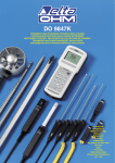
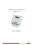
1.2 General information
MP01 module:
The MP01 module from the PME product line is a multi-channel DC amplifier
suitable for connection to DC voltage sources ("10 V), direct current sources
("20 mA; 4 - 20 mA), Pt100 resistance thermometers, and thermocouples. 4
channels are provided for voltage, current and thermocouples, plus 2
channels for Pt100 resistance thermometers or resistors (4-wire
measurement). The MP01 module is set up and parameters assigned via the
keyboard and display or with the aid of the PME Assistent program. The PME
Assistent program gives you a simple operator interface under MS-Windows
for assigning parameters to the modules (described in the ”PME Assistent”
online help).
I
DC transducer
excitation
U
A
D
Power supply
galvanically isolated
µP
D
Intelligent signal
conditioning,
e.g. limit value switch
Keyboard and display
A
24 V voltage supply
Scalable Analogue output
Control inputs and outputs
CANopen interface
MP01
A0598-6.6 en
HBM
8
Fig. 1.1:
PME MP01
Block diagram of MP01 module
The amplifier (MP01) uses a multiplex process. Channels can be selected or
switched off as required, so that a max. of 4 active channels are available.
NOTE
In the event of current measuring, an open input will result in a
measured value of 0. In all other cases, an open input can result in any
measured values.
HBM
A0598-6.6 en
PME MP01
2
9
Selecting amplifier settings with DIP switches
NOTE
The adjustment/alteration of DIP switch settings must take place before
fitting the PME.
Various settings are made with DIP switches and can be read off using the
display (see Chapter 5.3). These are the settings for
Sensor type, Analogue output, Synchronisation, Terminating bus
impedance, Edge steepness.
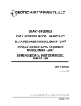
To set the DIP switches, you must proceed as shown in Fig. 2.1.
DIP switch layout plan
1
2
Screw off
cover
S4
S8
S9
S10
S11
S12
S6
S7
S5
S6-S9
Fig. 2.1:
Open housing, position of DIP switch
NOTE
Marking of switches:
The instructions of this manual and the marking inside the cover are
authoritative for the switches. The marking on the boards is to be
ignored.
A0598-6.6 en
HBM
10
PME MP01
Factory settings:
Amplifier type MP01; thermocouple sensor type; analogue
output "10 V
Bottom S10, S11 and S12
circuit
Sensor type
board:
S4, S6, S7, S8, S9;
ON
1
Top
2
circuit (S5 is mounted onto
3
board: the upper board from
the bottom side)
1
2
3
1
2
3
4
5
6
ON
S4
ON
S9
S6 - S9
1 2 34 5 6
ON
ON
S6
6
5
4
3
2
1
S7
ON
S5
3
2
1
S12
1
2
3
4
5
6
ON
Sensor type
1
2
3
4
5
6
ON
S11
ON
S10
S8
6
5
4
3
2
1
ON
1
2
3
4
5
6
1
2
3
4
5
6
ON
ON
Analogue
output
1 2 3
ON
S10
1 2 3456
Master/
Slave
ON
S11
12 34 56
Analogue
output
Sensor
type
No
function
HBM
ON
S12
1 23456
Amplifier type MP01
No
function
WARNING
Switch positions must not be
changed!
A0598-6.6 en
PME MP01
11
Factory setting:
S8
S4
S9
S6
S11
S7
S5
Sensor type 1)
ON
DC voltage
ON
ON
12 3 4 56
1 23456
ON
ON
2-wire
transmitter
1 23456
ON
ON
S4
S6 - S9
12 3 4 56
1 23456
ON
ON
123
ON
S11
S4
S6 - S9
12 3 4 56
1 23456
ON
ON
123
ON
S4
S6 - S9
S11
12 3 4 56
123
ON
S11
Thermocouple
S4
S6 - S9
12 3 4 56
Pt100
123
ON
S11
Direct current
S4
S6 - S9
S11
1 23456
123
Analogue output2)
ON
"10 V
ON
S11
V
1 23456
S5
123
ON
"20 mA
S11
ON
1 23456
mA
ON
4 - 20 mA
S11
S5
123
1 23456
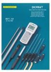
Fig. 2.2:
1)
2)
Setting up the amplifier
View/check on the display under the TRANSDUCER group, parameter ”TrnsdTyp”; see Page 27
Viewing/checking on display under the ANALOGUE OUTPUT group, parameter ”Mode Vo”, see Page 27
A0598-6.6 en
HBM
12
PME MP01
ON
Synchronisation
S10
Master
1 23456
S10
ON
Slave
S10
1 23456
Fig. 2.3:
Setting up the amplifier (continued)
Terminating bus resistor
S14
Toggle switch for termination resistor
(see page 20)
ON
Fig. 2.4:
HBM
OFF
Toggle switch for termination resistor
A0598-6.6 en
PME MP01
3
13
Fitting/removing the MP01
Fig. 3.1:
Fitting on a support rail
Fig. 3.2:
Removing
CAUTION
The support rail must lie on protection circuit potential
A0598-6.6 en
.
HBM
14
PME MP01
3.1 Connecting several modules
Ribbon cable jack-connector
Subsequent devices are
interconnected via this
connector.
Colour coding
at Pin 1
1.
2.
3.
58mm
Recommended
spacing of ribbon cable
jack-connectors
Fig. 3.3:
Connecting the ribbon cable
You can connect several MP01 modules with a ribbon cable. This cable is
used for local connection of the voltage supply and synchronisation between
the modules. You should not interconnect more than 8 modules with one
ribbon cable.
HBM
A0598-6.6 en
PME MP01
4
15
Connections
Warning
Please take note of the safety instructions before putting the device into
operation.
The following maximum input values (levels) may be applied at the input
terminals (higher values could result in damage to the device):
Operating mode
max. Input value
Voltage, Thermocouples, Pt100
Current
"30V
"100mA
4.1 Functional overview of MP01
Local linking of CAN bus, voltage supply and synchronisation between the modules
Plug-in terminal 1:
24 V power supply with potential separation,
CAN bus, synchronisation
LED
Terminal plug 2:
CAN adapter for PC/laptop connection,
assigning parameters via CAN bus
Two line LCD display
S
E
N
S
O
R
1
3
2
4
Touch-sensitive control
buttons
Sensor connection SENSOR 3/4 (5-pin
terminal plug); Channel 3 and Channel 4
Plug-in terminal 3:
Potential-separated1) Control inputs (24 V level),
Analogue output
Sensor connection SENSOR 1/2 (5-pin
terminal plug); Channel 1 and Channel 2
1)
Plug-in terminal 4:
Potential-separated control outputs (24 V level),
external power supply of control outputs
Potential separation in relation to amplifier (measuring circuit) and voltage supply
Control inputs and outputs have the same reference potential
A0598-6.6 en
HBM
16
PME MP01
4.2 Voltage supply and control inputs/outputs
There are four removable terminal plugs provided for making connections.
Connect power supply:
Warning
The MP01 module must be connected to a power supply
of 18-30 V (24 Vnom).
D Twist wires of the power supply and fit end sleeves.
D Screw ends of conductors to terminal plug 1.
D Insert terminal plug in top jack socket.
D Switch on power supply.
Power supply
0V
24 V
Terminal plug 2
SYN
Label
Terminal plug 1
Terminal plug 3
S
E
N
S
O
R
CAN_L CAN_H
1
3
2
4
Terminal plug 4
Label
Label
0V
24 V
OUT
±10 V
±20 mA
4 - 20 mA
OUT1
IN3
IN2
IN4
OUT2
OUT3
IN1
IN = Digital input
OUT4
OUT = Digital output
You will find more about inputs and outputs in Chapter 6, Page 31.
CAUTION
Fig. 4.1:
In the event of a power failure at the MP01 module, all
control outputs will be set to 0 V.
Pin assignment for terminal plugs
The 4 terminal plugs are coded, so they can be inserted in the 4 jacks with no
danger of a mix-up. The jacks are provided with coded lateral guides and the
terminal plugs with coded pins.
HBM
A0598-6.6 en
PME MP01
17
4.2.1 External voltage supply for control outputs
Example: PLC connection
MP01 module
OUT3
max. 0.5 A
PLC
Relay
max. 0.5 A
OUT1
24 V*
=0 V*
24 V
=0 V*
Terminal plug 4
Fig. 4.2:
Connection to a PLC
Control inputs are provided at terminal plug 3, and control outputs at
terminal plug 4 and are internally electrically insulated from the supply voltage
(see also Chapter 6, ”Declaring the significant parameters” Page 31).
*) The control outputs must be supplied with an external voltage (ground and
24 V [maximum +30 V]).
4.3 Sensors
MP01:
A maximum of 4 sensors can be be connected to the sensor connection
terminals SENSOR 1/2 and SENSOR 3/4. The individual sensors are
assigned parameters via Channels 1-4.
4 channels are provided for connecting voltage/current and thermocouples;
for instance, you could connect 4 DC power supplies. 2 channels (Channel1
at SENSOR1/2 and Channel2 at SENSOR3/4) are supplied for Pt100
resistance thermometers; you can connect a maximum of two Pt100s (using a
four-wire connection).
S
E
N
S
O
R
1
NOTE
The labelling on the front of the MP01 refers to sensors 1 to 4
and is not identical to the terminal labels.
2
A0598-6.6 en
You will find the terminal assignment in Fig. 4.4.
HBM
18
PME MP01
Sensor connection terminal
SENSOR 3/42 (for Channel 3 and
Channel 41))
Sensor connection terminal
SENSOR 1/2 (for Channel 1 and
Channel 21))
S
E
N
S
O
R
S
E
N
S
O
R
Terminal:
1+
23
4+
5-
Terminal:
1+
23
4+
5-
Measurement on Channel 1 or Channel 3
DC voltage sources ("10 V)
1
(+) Measuring
signal (+)
U
I
Measuring
(-)
signal (-)
Cable shielding
DC power supplies ("20 mA; "4 - 20 mA)
2
(-)
Hsng.
1
(+) Measuring
signal (+)
(-)
Measuring
signal (-)
Cable shielding
Measuring
signal (-)
2
Cable shielding
Hsng.
Thermocouples
2-wire transmitter
I
Thermocouple
Extension wire
2
Hsng.
Extension wire
Type
Pt100
Supply current
Measuring signal (+)
R
Cable shielding
Measuring signal (-)
Supply current
1
4
J
K
T
S
Hsng
.
5
2
HBM
1 (+)
+ Measuring
signal (+)
Measuring
signal (-)
Cable shielding
1
2
Hsng
.
2 (-)
Iron
Nickel-Chrome
Copper
Rhodium-Platinum
Copper-Nickel
Nickel
Copper-Nickel
Platinum
Note regarding Pt100
Sensor connection: Channel 1 and Channel 3
Setup: Channel 1 and Channel 2
1)
Fig. 4.3:
1
(+) Measuring
signal (+)
Channel selection see Chapter 5.3.1
Sensor connection MP01
A0598-6.6 en
PME MP01
19
Measurement on Channel 2 or Channel 4
DC voltage sources ("10 V)
(+) Measuring
signal (+)
U
(-)
Measuring
signal (-)
Cable shielding
DC power supplies ("20 mA; "4 - 20 mA)
I
(-)
5
Hsng.
4
(+) Measuring
signal (+)
Measuring
(-)
signal (-)
Cable shielding
Measuring
signal (-)
Cable shielding
Hsng.
Thermocouple
Extension wire
+ Measuring
signal (+)
Measuring
signal (-)
Cable shielding
5
Hsng.
Extension wire
Type
Pt100
Supply current
Measuring signal (+)
R
5
Thermocouples
2-wire transmitter
I
4
(+) Measuring
signal (+)
4
Cable shielding
Measuring signal (-)
Supply current
1
4
J
K
T
S
1 (+)
4
5
Hsng
.
2 (-)
Iron
Nickel-Chrome
Copper
Rhodium-Platinum
Copper-Nickel
Nickel
Copper-Nickel
Platinum
Hsng
.
5
2
Note
Note regarding Pt100
Sensor connection: Channel 1 and Channel 3
Setup: Channel 1 and Channel 2
Fig. 4.4:
Measurement
on channel
1
2
3
4
Connect to terminal
1 and 2
4 and 5
1 and 2
4 and 5
Sensor connection MP01
NOTE
Use standard HBM cable for the transducer connection. When using
other shielded, low-capacitance measuring cable, connect the
transducer cable shielding to the connector housing in accordance with
the HBM Greenline concept (publication S1578). This ensures EMC
protection.
A0598-6.6 en
HBM
20
PME MP01
4.4 CAN interface
The CAN bus is connected via terminal plug 1. A maximum of 32 CAN users
can be connected in one bus segment - each with different CAN address- (in
accordance with the CANopen specification).
The CAN bus needs a 120 Ω terminating resistor in the first and last bus
users. A terminating resistor is integrated into the MP01 module which is
activated by the toggle switch S14 (see Page 12).
Low
Fig. 4.5:
High
Connect CANinterface
CAN high
CAN low
CAN
connection
in accordance
with Fig. 4.5
First device in
the bus line
Switch in terminating resistor in
the PME (see Page 12)
Fig. 4.6:
Last device in
the bus line
Do not switch in
terminating resistor
Switch in terminating
resistor in the PME
CAN bus operation with several modules (as per Standard maximum 32)
Note
If the first or last device in a bus circuit is not a PME module, then a
120 W resistor must be switched on at these pieces of equipment.
HBM
A0598-6.6 en
PME MP01
21
4.5 Synchronisation
Synchronisation of modules guarantees the simultaneous acquisition and
processing of measurement data.
S10
S10
ON
ON
Slave
Master
S10
1 2 3 45 6
Fig. 4.7:
1 2 34 5 6
Set up master/slave
Zur When synchronising several modules, one device is to be declared as the
master. Set up all the other instruments as slaves.
Synchronisation between modules should always - even if working without a
CANbus - be effected via the ribbon cable.
A0598-6.6 en
HBM
22
5
PME MP01
Setting up and operation
5.1 Operating principles
Display in measuring
mode:
-18.00
oC
Status field
↑
↓
Measured value
Unit
Flashes in status field, if parameter value is editable
These keys
+
-
are pressure-sensitive:
Hold key down - values run through (the harder you press, the faster they run
through)
Hold key down briefly - switch values one at a time
Functions of keys:
SET
1. Switching from measuring mode
to Set-up mode
2. Select the first parameter within
the group.
3. Confirm input
4. Return to measuring mode
(press for 2 secs.)
HBM
-
+
Select
parameter/group
+
-
A0598-6.6 en
PME MP01
23
Measuring mode
Password status inactive
(factory setting):
Password status active
SET 2 secs.
SET 2 secs.
PASSWORD
DIALOGUE
Set-up mode
Enter password:
SET
Password
SET
Input mode
+
↑
↓
Enter required password
(factory setting 0)
-
Confirm
SET
Example:
Change
settings:
+
SET
+
Enter numerical
value
Select
group
TRANSDUCER
Select first
parameter
Unit
Select required parameters
SET
+
SET
Return to
measuring
mode:
CONDITIONING
>0<
kN
Filter
_ _ Hz
↑
↓
Enter numerical value or
Select table value
2.000
0.5 Hz
Confirm
SET 2 secs PME queries: Save?
2x
Saving
A0598-6.6 en
Go to input mode
NVal mV/V/V
0.000
Select table
value
SET
YES
NO
SET
+/-
SET
Save?N
o
HBM
24
PME MP01
During measurement you can press + - - view on display:
1. Values of active channels
2. Analogue output value
2. status of digital I/Os
3. the error list
The symbol is displayed in the status field ! , this indicates an error which is
described in the error list.
Status field
-18.00
oC
Measured value
Unit
The first position in the status
field shows the channel
number.
Symbol in status
field
Display mode
no character
Gross signal
>T<
Net signal
Maximum peak value signal
+
-
every
4
times
Minimum peak value signal
if
active
Peak/peak signal
VIn1)
Input signal
V or mA
Analogue output signal
set,
Outp
Inpt
not set
Status of input and output
e.g.
ERRORS
Ch2StoreMax
Error messages
During measurement, the character !
indicates a module failure. Error messages
are channel-specific.
The current failures which have occurred are
automatically displayed one after another in
display mode ”ERRORS Ch1...4” (can be
reached with + ).*)
Status field
1)
!
Failure occurred
or mAin, mV, Ω
*) see Chapter 8 ”Error messages”, Page 58
HBM
A0598-6.6 en
PME MP01
25
5.2 Commissioning
D Set the DIP switches according to Chapter 2 (page 10 and 11) ein.
D Connect the power supply cable and transducers to the module as
described in Chapters 4.2 and 4.3.
CAUTION
Please note the safety instructions here!
D Switch on the power supply.
The device carries out a function test (approx. 15 secs.) and is then in
measuring mode, if everything runs correctly. During the function test,
the control outputs remain at 0V.
In addition, the yellow LED indicates that the MP01 is ready to start
measuring.
You will find the meanings of other LED signals in Chapter 8 ”Error
messages”.
A0598-6.6 en
HBM
5.3 Guide to all groups and parameters
SET
+
Up
-
Overview of parameters
Down
-
+
SET
Groups
DIALOGUE
PARAM.
SET
CHANNEL
DISPLAY
Ch1*)
TRANSDUCER
Ch1*)
TRANSD.CAL.
Password
Load ?
ChSelect
DecPoint
Enable
P1Meas.?
>0< Set ?
SourceVo
PassStat
Save ?
MAINGRP
Step
Unit
P1 Vin
>0< %1)
Language
MAINGRP
MAINGRP
TrnsdTyp
>T<Enable
P1
%1)
Linearis2) P2Meas.?
I.ParaS
CONDILIMIT
ANALOG
TION.
VAL.1..2
OUTPUT
Ch1*)
Ch1*)
Ch1*)
PEAKVAL.
STORE
Ch1*)
IN/OUT
CAN-BUS
ADDITION
FUNCTION
Enable
Enable
Output1
Baudrate
AmplType
Mode Vo
Source
InputMin
ModeOut1
Address
PrgVers
Zero %1)
SwtchDir
Output2
Profile
u0t Save
Level
InputMax
%1)
ClearPkV
ModeOut2
PDO Ch1...Ch4
uTt Save
MAINGRP
Output3
OutR. ms
Keyboard
>T< Set ?
Zero V
>T< %1)
FScl %1)
Hyst %1)
Filter
FScl V
OnDelay ms
ModeOut3
PDO-Frmt
SNo prior version
FiltChar
MAINGRP
OffDlay ms
Output4
MAINGRP
HW-Vers.
MAINGRP
ModeOut4
I.Displ.
Inp.Pola2)
I.Transd
ZeroVin3)
I.TrdCal
Zero
%1)3)
I.Condit
NVal Vin3)
I.Analog
NVal%1)3)
Zeroing 1...4
I.LimVal
MAINGRP
Tare 1...4
P2 Vin
P2
%1)
MAINGRP
MAINGRP
I.PStore
PkMomMx1..4
I.I/O
PkHldMx1...4
I.CAN
PkMomMn1..4
I.AddFnc
PkHldMn1...4
MAINGRP
ParaCo1
MAINGRP
ParaCo2
InpFunc
MAINGRP
Preset with DIP switches
MAINGRP:
SET
return to group
Depending on the unit selected 2) only in the case of thermocouples
Ch1 to Ch4, depending on the channel selected
3)
not in the case of thermocouples and not in the case of Pt100
a598-6.6 en
26
1)
*)
with
Meas. value
YES
Groups
NO
+
+
DIALOGUE
PARAM. SET
-
SET
SET
Password
SET
a598-6.6 en
PassStat
active
SET
PASSWORD
27
5.3.1 Set up all parameters
2sec
↑____
↓
Password
CHANNEL
-
SET
SET
↑
↓ ____
+/-
Load ?
PassStat
SET
Language
SET
↑ active
↓
inactive
SET
-
Transducer
+
DISPLAY
-
Ch1
*)
SET
↑
↓ ParaS.1
ParaS.2
ParaS.3
ParaS.4
FactSet
No
+
+/-
+
SET
Specify password
Enter password
+/-
+
.00000
DecPoint
↑ .0000
↓
.000
.00
.0
.
SET
+/-
+
+/-
I.ParaS
Continue with
DIALOGUE
+
Deutsch
↑ English
↓
Francais
-
+/-
Save ?
SET
I.Displ.
-
I.Transd
Back to
MAINGRP
SET
↑ ParaS.1
↓
ParaS.2
ParaS.3
ParaS.4
No
Step
+/-
ChSelect1)
I.Condit
Channl3
Channl4
+
I.Analog
I.LimVal
SET
free
↑
↓ locked
+/-
+/-
SET
Back to
MAINGRP
Parameter values
+
I.I/O
Select parameter
-
I.CAN
↑
↓ Flashes if parameter value editable
I.AddFnc
Back to
MAINGRP
0005
0010
0020
0050
0100
0200
0500
1000
+/-
I.PStore
SET
↑
↓ Channl1
Channl2
SET
↑
↓ 0001
0002
Back to
MAINGRP
SET
I.TrdCal
SET
*)
depending on the channel selected
1)
in the case of PT100: 2 channels only
Note:
If a group cannot be selected, check under DIALOGUE whether the group has been enabled.
Confirm input:
+/-
=
+
SET
or
press
-
Return to measuring mode:
SET
2sec
Groups
TRANSDUCER
Display
TRANSD.CAL. 4)
+
Ch1*)
-
Enable
↑ ON
↓
SET
Unit2)
OFF
SET
Preset5) with DIP switches
S6..S9 and S11
TrnsdTyp
SET
Linearis3)
SET
-
Inp.Pola3)
ZeroVin1)4)
Zero %1)4)
NVal mV/V4)
SET
%1)4)
SET
SET
SET
SET
SET
set
withswitches
J
↑
↓↑
↓ Type
Type K
+/-
Type S
Type T
↑
↓ normal
invert.
+/-
↑
↓ 0.00000
↑ 0.00
↓
+/-
↑ 2.0000
↓
↑
↓ 10.00
Back to
MAINGRP
*)
depending on the channel selected
1)
depending on the unit selected
+/-
+/-
+/-
P1 mV/V
↑ No
↓
Yes
SET
>0<
P1
oC1)
SET
oC1)
↑
↓ No
Yes
SET
>T<Enable
+
>T< Set ?
+/-
↑ 0.00
↓
SET
↑ 0.0000
↓
↑ 0.0000
↓
↑ No
↓
Yes
SET
P2Meas.?
SET
↑
↓ No
Yes
+/-
P2 mV/V
SET
-
oC1)
SET
Preset with
DIP switches S11 and S5
Mode Vo
10V
+/-
↑ Bessel
↓
Butterw
SET
+/-
+/-
+
SET
Back to
MAINGRP
SET
set
withswitches
Zero oC1)
SET
Zero V
SET
↑ 0.00
↓
FScl oC1)
SET
↑
↓ 10.00
+/-
FScl V
SET
↑
↓ 10.00
+/-
↑ 0.00
↓
+/-
SET
↑ 0.0000
↓
-
+/-
+
+/-
↑ 0.0000
↓
FiltChar
↑↓
↑Gross 1
↓
Gross 2
Gross 3
Gross 4
Net 1
Net 2
Net 3
Net 4
CAN
+/-
↑
↓ 0.00
SET
Filter
+/-
P2
oC1)
SET
+/-
↑ ON
↓
OFF
SET
SourceVo
+/-
>T<
-
SET
>0< Set ?
+/-
2)
↑ 0.05Hz
↓
0.1Hz
0.2Hz
0.5Hz
1Hz
2Hz
5Hz
10Hz
20Hz
50Hz
100Hz
200Hz
+/-
+/-
SET
Back to
MAINGRP
Back to
MAINGRP
SET
5)
see Page 11,
a598-6.6 en
28
in the case of Pt100/Thermocouple: Unit only
°C; °F; K
3) in the case of thermocouples only
4) not in the case of thermocouples and not in the
case of Pt100
SET
+/-
kg ↓
↑
T
kT
TON
lb
oz
N
kN
Bar
mBar
Pa
Pas
hPas
kPas
psi
µm
mm
cm
m
inch
Nm
kNm
FTLB
INLB
µm/m
M/S
M/SS
p/0
p/00
ppm
S
MP
MN
oC
oF
K
V
mA
g
-
Limit val.1
+
Ch1*)
SET
P1Meas.?
+/-
NVal
-
ANALOG OUTPUT
+
Ch1*)
SET
SET
+
CONDITION.
+
29
a598-6.6 en
Groups
Analog output
LIMIT VAL.1
LIMIT VAL.2
Ch1*)
+
Ch1*)
-
PEAKVAL. STORE
+
-
Enable
Source
SET
SET
↑ On
↓
Off
Enable
+/-
-
Gross
↑ Net
↓
InputMin
SET
+/-
SwtchDir
SET
↑ Higher
↓
Lower
+/-
InputMax
+
Level oC1)
SET
↑
↓ 0.00
↑ Ch1LmV1
↓
Ch1LmV2
SET
SET
SET
↑ On
↓
Off
↑ Gross
↓
Net
Gross
↑
↓ Net
CAN-Bus
+
-
SET
SET
+
IN/OUT
+
Ch1*)
+/-
+/-
Output1
SET
ModeOut1
SET
Zeroing 1...4
SET
Accordingly
Output 2..4
and ModeOut
2...4
+/-
Ch2LmV1
Ch2LmV2
Ch3LmV1
Ch3LmV2
Ch4LmV1
Ch4LmV
Error
inactive
Act. On
↑
↓ Act.Off
+/-
+/-
Tare 1...4
+/-
+
-
Hyst oC1)
OnDelay ms
SET
SET
↑
↓ 0.00
↑
↓ 0000.0
ClearPkV
+/-
SET
No
↑
↓ Yes
+/-
PkMomMx1...4
↑
↓ Input1
Input2
-
PkHldMx1...4
+/SET
+/-
Input3
Input4
NoInput
Back to
MAINGRP
PkMomMn1...4
OffDlay ms
SET
↑ 0000.0
↓
+/-
PkHldMn1...4
SET
ParaCo1
Back to
MAINGRP
ParaCo2
Same applies to Limit value 2
*)
depending on the channel selected
1)
depending on the unit selected
InpFunc
SET
Back to
MAINGRP
SET
↑ free
↓
locked
+/-
Groups
In/Out
+
CAN-Bus
ADDITIONFUNCTION
-
SET
Baudrate
SET
10 kB
↑
↓ 20 kB
+/-
50 kB
100 kB
125 kB
250 kB
500 kB
1000 kB
Address
SET
↑
↓
000
+
-
MEAS MODE
SET
SET
AmplType
Save ?
SET
↑ Yes
↓
No
+/-
PrgVers
+/-
+
>0< Save
SET
↑ Volatil
↓
+/-
>T< Save
SET
↑ Volatil
↓
+/-
Save
Meas. value
+
-
Profile
SET
↑ No Prof
↓
+/-
-
PDO Ch1...
PDO Ch4
SET
↑ Gross
↓
Net
PkVMax
PkVMin
PKV PP
OFF
HW Synchr
Slave
SET
+/-
Keyboard
SET
Save
Preset with
set
withswitches DIP switch S10
↑
↓ Slow
Fast
Medium
+/-
SNo
SET
OutR ms
SET
↑
↓
PDO-Frmt
SET
↑ Float
↓
Int 32
3.0
+/-
+/-
HW-Vers.
SET
Back to
MAINGRP
Back to
MAINGRP
30
a598-6.6 en
PME MP01
6
31
Declaring the significant parameters
Group
Parameters
Meaning
DIALOGUE
Password
Specifying (changing) a password, 0000 - 9999
(Factory preset password: 0000)
PassStat
Define password status:
active=password must be entered;
inactiv=PME can be operated without a password
I.ParaS to
I.AddFnc
Access to group via keyboard free or locked.
Load ?
You can either load the factory settings (into all 4 channels
simultaneously) or one of the four stored parameter sets.
Save ?
All device settings can be saved in four parameter sets and
not be affected by a power failure. Every time you switch
from Setup to Measuring mode, you are asked whether or
not the change is to be saved. The data is backed up
permanently if you confirm the query with ”Yes” on quitting
Setup mode.
ChSelect
Specify channel to which parameters are to be assigned.
Note: channels (maximum 4) can be selected and switched
off as required.
PARAM. SET
CHANNEL
A0598-6.6 en
HBM
32
PME MP01
Group
Parameters
Meaning
TRANSDU
CER
TrnsdTyp
Selection of sensor type:
DC voltage, direct current, transmitter with 2-wire
connectivity, Pt100, thermocouple
Zero VIn
Zero %1)
NVal VIn
NVal %1)
Setting up in accordance with
transducer characteristics
Display (%)
Example:
NVal %
-10
70
NomValue
50
Zero (V)
10
Input signal (V)
ZeroVin
Information on scaling
Input characteristics:
The range of values of scale factors is limited. Scaling
depends on the resolution selected. In the event of settings
which lead to exceeding the respective limits, the message
”Scaling error” appears (see Page 59).
maximum display resolution:
minimum display resolution:
TRANSD.CAL.
P1Meas.?
P1 V
P1 %1)
999 999 digits at 6.67 % of
amplifier input range
10 digits at 100 % of
amplifier input range
Acceptance of signals emitted by sensor in case of defined loading
%
p2
P1Meas.? YES
0V
P1
(allocate physic. unit)
enter 50 %
p1
V
P2Meas.? YES
P2
10 V
enter 70 %
Note: If the zero point or nominal value are modified, P1 and P2 will be lost.
1)
Depending on the unit selected
HBM
A0598-6.6 en
PME MP01
Group
33
Parameters
Meaning
Difference tare/zero: the zero (>0<) affects the gross and
net values. The Tare (>T<) only affects the net value.
CONDITION
>0< Set ?
Trigger zero balance; current value (physical unit) zero
>0< %1)
Enter zero value. Zeroing effects both, the gross value and
the net value.
>T< Enable
Tara value for indication on the display.
>T< Set ?
Trigger taring; net value set to 0
>T<
oC1)
Filter
FiltChar
Input tare value. Taring has an effect on the net value.
0.05 Hz
0.1 Hz
0.2 Hz
0.5 Hz
1 Hz
2 Hz
5 Hz
10 Hz
Impulse response
20 Hz
50 Hz
100 Hz
250 Hz
The diagram shows an impulse
response with an overshoot of approx.
10 %. The amplitude response drops
off steeply.
Time
Best frequency
response
(Butterworth)
Impulse response
The diagram shows an impulse
response with a very small overshoot
(<1 %) or none at all. The amplitude
response drops off less steeply.
Time
Best course over time
(Bessel)
1)
Depending on the unit selected
A0598-6.6 en
HBM
34
PME MP01
Group
Parameters
Meaning
ANALOG
OUTPUT
SourceVo
You can choose the gross or net values, as well as the peak
value as the source of the analog signal.
Mode Vo
With DIP switches S11 and S5, you specify the signal mode
for the analog output. The following options are available:
"10 V, "20 mA, 4...20 mA
V
Zero oC1)
Zero V
FScl oC1)
FScl V
FScl V
Zero V
0
Zero oC
FScl oC
Physical unit
Information on scaling
Output characteristics:
The scale factor for the analog output is a result of the input
and output characteristics. If the set nominal value
corresponds to the measuring range of, for example, 10 V,
then the minimum output voltage to be set is 0.5 V. In the case
of settings which lead to exceeding the respective limits, you
are given the message ”Analog scaling error” (see Page 59).
Scale range analog output min.: 0.5 V at 100 % of input measuring range
Scale range analog output max.: 10 V at 3.5 % of input measuring range
1)
Depending on the unit selected
HBM
A0598-6.6 en
PME MP01
35
Group
Parameters
Meaning
LIMIT VAL.
1...2
Source
You can select one of the following as the source of the limit
value signal: Gross, Net, Peak value Max/Min/Peak-to-peak
SwtchDir
Level
Hyst
Functions and parameters of limit values
Limit1, ON
Level
Over limit
Below limit
Hyst
OFF
OFF
Hyst
Limit2, ON
24 V
0V
Level
Limit1 ON
24 V
0V
Limit2 ON
PEAKVAL.
STORE*)
A0598-6.6 en
OnDelay
ms
Starting delay; if the limit value level is exceeded, this change
only has an effect at the output after the delay time (OnDelay).
OffDlay
ms
Cut-off delay, as OnDelay
InputMin/
Max
You can select one of the following as the source of the peak
value signal: gross, net
ClearPkV
The peak value can be deleted.
HBM
36
PME MP01
Inputs /Outputs
Terminal plug 3: provided here for the control of PME functions
are 4 inputs.
Terminal plug 4: here you have 4 outputs at your disposal.
Group
IN/OUT
Parameters
Meaning
Output1...4 Outputs 1 - 4 can be assigned the following functions for each
channel:
Limit value 1 to 2, error, inactive
ModeOut
1...4
Output signal is inverted (Act. On) or not inverted (Act.Off).
The functions listed can be freely allocated to the remotes
(I/Os).
Functions
Input value 0 V
Taring
Taring is started upon alternation from 0 V to 24 V
Zero
balance
Current measuring signal is set to zero upon alternation from
0 V to 24 V
PkMomMx
”Peak value” operating mode
for PkMax
”Current value” operating
mode for PkMax
PkMomMn
”Peak value” operating mode
for PkMin
”Current value” operating
mode for PkMin
PkHldMx
Memory contents of PkMax
are updated
Memory contents of PkMax
are frozen
PkHldMn
Memory contents of PkMin
are updated
Memory contents of PkMin
are frozen
ParaCo1
Selection of parameter sets and binary
coded inputs
ParaCo2
HBM
Input value 24 V
Parameter set
ParaCo2
ParaCo1
1
0
0
2
0
1
3
1
0
4
1
1
A0598-6.6 en
PME MP01
37
Parameters
IN/OUT
PkMomMx
PkMomMn
PkHldMx
PkHldMx
PkHldMn
Meaning
”Peak value” operating mode
Measuring signal
Amplitude
Group
Function
Operating mode
Trend of stored
value
Hold
Run
Peak value (Store1)
t
Hold
Run
Current
value
t
”Current value” operating mode
Amplitude
Measuring signal
Function
Operating mode
CAN -Bus
ADDITION
FUNCTION
*)
1)
2)
3)
Run
Hold
Current value
t
Run
Run
Baud rate
10 kB, 20 kB, 50 kB, 100 kB, 125 kB, 250 kB, 500 kB, 1000 kB
Address
From 1 to 127 (8 data bits)
Profile
DS401 (Device profile for I/O modules)
or DS404 (Device Profile for Measuring Devices and Closed
Loop Controller) in preparation
PDO
Ch1...
PDO Ch4
The signal output via the CAN bus is selected: Gross, Net or
Peak value max/min; Peak-to-peak; OFF1)
PDO Ch1: 1.PDO (sends the selected signal from Channel 1
as the first PDO)
PDO Ch2: 2.PDO (sends the selected signal from Channel 2
as the 2nd PDO)
PDO Ch3: 3.PDO (sends the selected signal from Channel 3
as the first PDO at the next higher ID)3)
PDO Ch4: 4.PDO (sends the selected signal from Channel 4
as 2nd PDO)2)3)
OutR. ms
Output rate. Specifies the interval (in ms) at which PDOs are
sent via the CAN interface.
>0< Save*)
With each zeroing procedure, the zero value is adopted into
the EEPROM (service life 100,000 cycles)
>T< Save*)
Save tare value immediately after taring
For all four channels simultaneously
In the case of OFF, the PDO is not transferred (PDO not valid)
Device address 127: 3rd and 4th PDO is sent to Address 1
If PDO Ch3 and/or PDO Ch4 are selected, the module address following the module must be left free
without fail.
A0598-6.6 en
HBM
38
PME MP01
7
CAN interface description
7.1 General
The MP01 module has a built-in CAN interface, via which both measured
values (data) can be transferred and parameters can be assigned to the
module. You are free to select the baud rate, but the maximum is 1 MBaud.
The protocol of the interface is orientated towards CANopen Standard.
7.2 Cyclical data transmission
Cyclical data is transferred in the form of “Process Data Objects” (PDOs,
according to CANopen specifications). Data which is of interest is sent
cyclically without further labelling under a CAN identifier specified previously.
A prompt message is not needed. How often PDOs are sent is set up as a
parameter (see object directory). Data formats with a length of more than one
byte are always sent in the sequence LSB-MSB.
Send PDO:
CAN identifier
1st - 4th data byte
5th data byte
384 (180 Hex) + module address
Measured value (LSB-MSB)
Status (object 2010)
Receive PDO:
CAN identifier
1st data byte
512 (200 Hex) + module address
Control word (object 2630)
Apart from these predefined PDOs, others can be set up according to
CANopen specifications (CIA-DS301) using mapping. Appropriate tools for
this are commercially available.
The exchange of cyclical PDOs is only started after the module has been put
into ”Operational” status. This takes place using the message
”Start_Remote_Node”
CAN identifier
1st data byte
2nd data byte
HBM
0
1
Module address (0 = all)
A0598-6.6 en
PME MP01
39
You can exit ”Operational” status again by means of the message
”Enter_Pre_Operational_State”:
CAN identifier
1st data byte
2nd data byte
0
128
Module address (0 = all)
7.3 Parameter assignment
Messages for assigning parameters to the module are transferred as
so-called “Service Data Objects” (SDOs, as per CANopen specifications). In
this case, the different parameters are addressed via an index number as well
as a sub-index number. Please see the object directory regarding the
allocation of these index numbers. Data formats with a length of more than
one byte are always sent in the sequence LSB-MSB.
Reading a parameter:
Query (PC or PLC at MP01)
CAN identifier
1st data byte
2nd + 3rd Data byte
4th data byte
5th - 8th data byte
1536 (600 Hex) + module address
64 (40 Hex)
Index (LSB_MSB)
Sub-index
0
Response (MP01 at PC or PLC)
CAN identifier
1st data byte
2nd + 3rd Data byte
4th data byte
5th - 8th data byte
1408 (580 Hex) + module address
79 (4F Hex); 1 byte data
75 (4B Hex); 2 bytes data
67 (43 Hex); 4 bytes data
Index (LSB-MSB)
Sub-index
Value (LSB-MSB)
Writing a parameter:
Send value (PC or PLC at MP01)
CAN identifier
1st data byte
2nd + 3rd Data byte
4th data byte
5th - 8th data byte
A0598-6.6 en
1536 (600 Hex) + module address
47 (2FHex) = 1Byte write
43 (2BHex) = 2Byte write
35 (23Hex) = 4Byte write)
Index (LSB-MSB)
Sub-index
Value (LSB-MSB)
HBM
40
PME MP01
Acknowledge (MP01 at PC or PLC)
CAN identifier
1st data byte
2nd + 3rd Data byte
4th data byte
5th - 8th data byte
1408 (580 Hex) + module address
224 (E0Hex)
Index (LSB_MSB)
Sub-index
0
Response in the event of an error when reading or writing parameters:
Error acknowledge (MP01 at PC or PLC)
CAN identifier
1st data byte
2nd + 3rd Data byte
4th data byte
5th - 6th data byte
7th data byte
8th data byte
HBM
1408 (580 Hex) + module address
128 (80Hex)
Index (LSB_MSB) or 0
Sub-index or 0
Additional error code:
10H: parameter value invalid
11H: Sub-index does not exist
12H: Length too big
13H: Length too small
20H: This service currently not executable
21H: - Due to local control
22H: - Due to device status
30H: Value range of parameter exceeded
31H: Value of parameter too large
32H: Value of parameter too small
40H: Value is incompatible with other settings
41H: Data cannot be mapped
42H: PDO length exceeded
43H: General incompatibility
Error code:
1: Object access not supported
2: Object does not exist
3: Parameters inconsistent
4: Prohibited parameter
6: Hardware failure
7: Type conflict
9: Object attributes inconsistent (sub-index does not exist)
Error class:
5: Service defective
6: Access error
8: Other error
A0598-6.6 en
PME MP01
41
7.4 Emergency objects
Byte
Conte
nts
0 byte
1st
byte
Emergency
error code
2nd byte
3rd byte
6th
byte
Manufacturer-specific error field
Error
register
(Object
1001H)
Error
code
4th byte
5th byte
7th
byte
Meaning
0
1000
5032
6311
6312
F001
F002
F020
FF03
FF06
FF07
No error
Fatal error (original calibration error)
ADC overflow (cable break in case of thermocouples)
Scaling error
Scaling error analog output
Measuring range overflow
Analog output overflow
Net overflow
Gross overflow
Peak value min.
Peak value max.
It is defined in the 3rd byte in which channel the error has occurred:
3rd
byte
1
2
3
4
0
Channels 1 to 4
total device
A0598-6.6 en
HBM
42
PME MP01
7.5 Object directory: communications profile section
as per CANopen (CIA-DS301)
Index
(hex)
Subindex
Name
Data type
Attr.
1000
1001
0
0
Device type
Error register
unsigned32
unsigned8
ro
ro
1003
1003
0
1..7
Predefined error array
Predefined error array
unsigned8
unsigned32
rw
ro
1005
1008
0
0
unsigned32
Vis string
rw
ro
I=8
1009
0
Vis string
ro
I=8
100A
0
Vis string
ro
I=15
100B
1012
0
0
Unsigned32
Unsigned32
ro
rw
1200
0..2
ro
1400
0..2
1. Receive PDO parameter
1401
0..2
2. Receive PDO parameter
1402
0..2
3. Receive PDO parameter
1403
0..2
4. Receive PDO parameter
1600
0..2
1. Receive PDO mapping
1601
0..2
2. Receive PDO mapping
1602
0..2
3. Receive PDO mapping
SDOParam
eter
PDOComm
Par
PDOComm
Par
PDOComm
Par
PDOComm
Par
PDO
mapping
PDO
mapping
PDO
mapping
HBM
Identifier SYNC message
Manufacturer’s device
designation.
Manufacturer’s hardware
version
Manufacturer’s software
version
Device address
Identifier EMERGENCY
message
Server SDO parameter
Values
Bit 0: Fatal error
Bit 4: Communication error
Bit 7: Manufacturerspecific
Number of errors
Byte 0..1:Error code:
corresponds to bytes
0 and 1 of
emergency object
Byte 2..3:
corresponds to bytes
3 and 4 of
emergency object
rw
rw
rw
rw
rw
rw
rw
A0598-6.6 en
PME MP01
43
1603
0..2
4. Receive PDO mapping
1800
0..2
1. Send PDO parameter
1801
0..2
2. Send PDO parameter
1802
0..2
3. Send PDO parameter
1803
0..2
4. Send PDO parameter
1A00
0..2
1. Send PDO mapping
1A01
0..2
2. Send PDO mapping
1A02
0..2
3. Send PDO mapping
1A03
0..2
4. Send PDO mapping
PDO
mapping
PDOComm
Par
PDOComm
Par
PDOComm
Par
PDOComm
Par
PDO
mapping
PDO
mapping
PDO
mapping
PDO
mapping
rw
rw
rw
rw
rw
ro
rw
rw
rw
Data structures:
PDO CommPar:
Index
Sub-index
0020
0
1
2
3
4
Name
Number of entries
CAN identifier for PDO
Transmission type
Off-time
Priority group
Data type
unsigned 8
unsigned32
unsigned8
unsigned16
unsigned8
CAN identifier for PDO (Sub-index 1):
Bits
Value
31 (MSB)
0
1
0
1
0
1
X
30
29
28..0
Meaning
PDO valid
PDO invalid
RTR allowed
RTR not allowed
11 bit ID
29 bit ID
CAN ID
PDO mapping:
Index
Sub-index
0021
0
1
2
...
A0598-6.6 en
Name
Number of mapped objects
1. mapped object
2. mapped object
...
Data type
unsigned8
unsigned32
unsigned32
unsigned32
HBM
44
PME MP01
Structure of a PDO mapping entry:
Index (16 bit) Sub-index (8 bit) Object length in bits (8 data
bits)
SDO parameter:
Index
Sub-index
0022
0
1
2
3
HBM
Name
Number of entries
COB ID client->server
COB ID server->client
node ID (optional)
Data type
unsigned8
unsigned32
unsigned32
unsigned8
A0598-6.6 en
PME MP01
45
7.6 Object directory: manufacturer-specific objects
Parameters relating to measured values are coded with figures scaled in the
appropriate range as Long (32 bit integer). The position of the decimal point is
defined in the object 2120Hex. Alternatively, these quantities are also
available as floating decimal point values (IEEE754-1985 32 Bit format) (see
Page 55).
Note: rop, rwp: PDO mappable
Index
(hex)
Subindex
2000
2001
2002
2003
2004
2005
1-4
1-4
1-4
1-4
1-4
1-4
2006
2010
1
1-4
2011
1-4
2020
1
A0598-6.6 en
Name
Measured values:
Gross measured value
Net measured value
Maximum
Minimum
Peak-to-peak
Measured value as
input quantity
Analog output value V
Measured value status
Measured value
status_2
I/O status
Format
integer32
integer32
integer32
integer32
integer32
integer32
integer32
unsigned8
Attr.
Values
rop
rop
rop
rop
rop
rop 5 Decimal places
depending on type
rop 3 Decimal places
rop Bit 0: Meas. value
Overflow
Bit 1: Analog output Overfl.
Bit 2: Scaling defective
Bit 3: EEPROM error
Bit 4: Limit value 1
Bit 5: Limit value 2
unsigned32 rop Bit 0: Channel OFF
Bit 1: Overfl. ADC
Bit 2: Overfl. Gross
Bit 3: Overfl. Net
Bit 4: Overfl. Analog output
Bit 5: Overfl. Maximum
Bit 6: Overfl. Minimum
Bit 7: Negative Overfl.
Bit 8: Limit value 1
Bit 9: Limit value 2
Bit 12: Scaling input
Bit 13: Scaling output
Bit 14: Nom.val. excdd.
Bit 15: Orig. cal. error
Bit 17: CAN bus Off
Bit 18: CAN Tx error
unsigned8 rop Bit 0..3: Inputs 1...4
Bit 4...7: Outputs 1...4
HBM
46
PME MP01
Index
(hex)
Subindex
2080
0
2081
2082
2083
Format
Attr.
Edit mode
unsigned8
ro
0
Restart executed
unsigned8
0
0
Serial number
Exit edit mode
vis. string
unsigned8
2101
0
Dialogue:
Dialogue language
unsigned16
2103
2104
0
1
2110
1
2111
2112
1
1
HBM
Name
Password
Enable keyboard and
menu
Parameter sets
Enable parameter set
Save parameter set
Number of enabled
parameter set
integer16
unsigned16
unsigned16
unsigned16
unsigned16
Values
1: Edit mode ON
0: Edit mode OFF
rw 1: Restart executed
0: Write = Delete
ro 12 characters
wo Write any value to
measured value display
afterwards
rw 1500 deutsch
1501 English
rw
rw 0:
Enable input
1:
Input locked
Bit 0: Password entry
Bit 1: Dialogue
Bit 2: Parameter set
Bit 3: Display
Bit 4: Sensor
Bit 5: Conditioning
Bit 6: Analog output
Bit 7: Limit values
Bit 8: Peak values
Bit 9: Inputs/outputs
Bit 10: CAN
Bit 11: Additional functions
Bit 12: Calibrate
Bit 13: Channel selection
Bit 15: Keyboard lock
rw 6600: Factory setting
6601: Parameter set 1
6602: Parameter set 2
6603: Parameter set 3
6604: Parameter set 4
rw See above
ro See above
A0598-6.6 en
PME MP01
Index
(hex)
2120
2121
2122
Subindex
47
Name
Format
Attr.
1
1
Display adaptation
Decimal point position
Step
unsigned16
unsigned16
rw
rw
0..5
110:
111:
112:
113:
114:
115:
116:
117:
118:
119:
1
Sensor
Physical unit
unsigned16
rw
1601:
1602:
1603:
1604:
1605:
1606:
1607:
1608:
1609:
1610:
1611:
1612:
1613:
1614:
1615:
1616:
1617:
1618:
1619:
1620:
1621:
1622:
1623:
A0598-6.6 en
Values
1
2
5
10
20
50
100
200
500
1000
V
mA
g
kg
T
kT
TON
lb
oz
N
kN
bar
mbar
Pa
Pas
hPas
kPas
psi
µm
mm
cm
m
inch
HBM
48
Index
(hex)
2122
HBM
PME MP01
Subindex
1
Name
Sensor
Physical unit
Format
Attr.
unsigned16
rw
Values
1624:
1625:
1626:
1627:
1628:
1629:
1630:
1631:
1632:
1633:
1634:
1635:
1636:
1637:
1638:
1639:
1640:
Nm
kNm
FTLB
INLB
µm/m
m/s
m/s2
percent
per mille
ppm
S
MPas
MN
Blanks
oC
oF
K
A0598-6.6 en
PME MP01
Index
(hex)
Subindex
2130
1
2132
49
Format
Attr.
Sensor type
unsigned16
ro
1-4
Linearisation
unsigned16
ro
2133
1-4
unsigned16
rw
2134
1-4
Inverting input signal in
the case of
thermocouple
Enable channel
unsigned16
rw
2140
2141
2142
2143
5
1-4
1-4
1-4
1-4
unsigned16
integer32
integer32
integer32
integer32
ro
rw
rw
rw
rw
2150
1-4
integer32
rw
Value as input quantity
2151
1-4
integer32
rw
Value as input quantity
2160
1-4
integer32
rw
Value as physical unit
2161
1-4
Enable reference point
Transducer null
Transducer null
Transducer sensitivity
Transducer nominal
value
Input characteristic
1. Point
Input characteristic
2. Point
Input characteristic
1. Point
Input characteristic
2. Point
integer32
rw
Value as physical unit
A0598-6.6 en
Name
Values
420: Volt
421: mA
422: 2-wire
transmitter
449: Thermocouple
501: Pt100
450: Type J
451: Type K
452: Type T
453: Type S
1: inverted
0: not inverted
1:
0:
Yes
No
Value as input quantity
Value as physical unit
Value as input quantity
Value as physical unit
HBM
50
Index
(hex)
PME MP01
Subindex
Name
Format
Attr.
Conditioning
Tare value
Zero balance value
Memory mode for taring
integer32
integer32
unsigned16
rw
rw
rw
Memory mode for zeroing
unsigned16
rw
unsigned16
rw
unsigned16
rw
unsigned16
rw
2180
2181
2182
1-4
1-4
1
2183
1
2184
1-4
2190
1
Enable net signal (for
display only)
Filter frequency
2191
1
Filter characteristics
HBM
Values
6611: transient
6610: permanent
6611: transient
6610: permanent
1: Yes
0: No
908: 0.05Hz
914: 0.1Hz
917: 0.2Hz
921: 0.5Hz
927: 1Hz
931: 2Hz
935: 5Hz
941: 10Hz
945: 20Hz
949: 50Hz
955: 100Hz
959: 250Hz
141: Butterworth
142: Bessel
A0598-6.6 en
PME MP01
Index
(hex)
Subindex
51
Name
21C0
1
Analog output
Analog output mode
(voltage/current)
21C1
1
Signal at analog output
21D0
21D1
21D2
21D3
1-4
1-4
1-4
1-4
A0598-6.6 en
Zero point analog output
End value analog output
Zero point analog output
End value analog output
Format
Attr.
Values
unsigned16
ro
unsigned16
rw
integer32
integer32
integer32
integer32
rw
rw
rw
rw
290: ±10V
291: ±20mA
292: 4..20mA
214: Gross Ch1
280: Gross Ch2
281: Gross Ch3
282: Gross Ch4
215: Net Ch1
285: Net Ch2
286: Net Ch3
287: Net Ch4
204: Max Ch1
260: Max Ch2
261: Max Ch3
262: Max Ch4
205: Min Ch1
265: Min Ch2
266: Min Ch3
267: Min Ch4
218: Peak-to-peak Ch1
270: Peak-to-peak Ch2
271: Peak-to-peak Ch3
272: Peak-to-peak Ch4
Value as physical unit
Value as physical unit
Value in V or mA
Value in V or mA
HBM
52
Index
(hex)
PME MP01
Subindex
Name
Format
Attr.
Values
unsigned16
rw
1: Yes
0: No
214: Gross 1-4
215: Net 1-4
204: Min 1-4
205: Max 1-4
218: Peak-to-peak 1-4
130: Above limit
131: Below limit
ms
ms
2210
1-4
Limit switches
Enable Limit value 1
2211
1-4
Input signal Limit value 1
unsigned16
rw
2212
1-4
SwtchDir Limit value 1
unsigned16
rw
2214
2215
2216
2217
2218
2220
1-4
1-4
1-4
1-4
1-4
1-4
Starting delay LVS 1
Cut-off delay LVS 1
Switching level Limit value 1
Hysteresis Limit value 1
Status Limit value 1
Enable Limit value 1
integer32
rw
integer32
rw
integer32 rwp
integer32
rw
unsigned8 rop
unsigned16 rw
2221
1-4
Input signal Limit value 1
unsigned16
rw
2222
1-4
SwtchDir Limit value 1
unsigned16
rw
2224
2225
2226
2227
2228
1-4
1-4
1-4
1-4
1-4
integer32
integer32
integer32
integer32
unsigned8
rw
rw
rwp
rw
rop
2260
1-4
Starting delay LVS 1
Cut-off delay LVS 1
Switching level Limit value 2
Hysteresis Limit value 2
Status Limit value 1
Peak values
Input signal Min store
unsigned16
rw
2261
1-4
Input signal Max store
unsigned16
rw
2263
1-4
Enable peak store
unsigned16
rw
Additional functions
Keyboard sensitivity
unsigned16
rw
2272
HBM
0
1: Yes
0: No
214: Gross 1-4
215: Net 1-4
204: Min 1-4
205: Max 1-4
218: Peak-to-peak 1-4
130: Above limit
131: Below limit
ms
ms
214: Gross 1-4
215: Net 1-4
214: Gross 1-4
215: Net 1-4
1: enable
2: locked
7601: low
7602: medium
7603: high
A0598-6.6 en
PME MP01
Index
(hex)
Subindex
53
Name
Format
Attr.
Values
unsigned16
rw
2310
1
Digital I/Os
Function Output 1
2311
1
Mode output 1
unsigned16
rw
2312
2313
2314
2315
2316
2317
2320
1
1
1
1
1
1
1-4
Function Output 2
Mode output 2
Function Output 3
Mode output 3
Function Output 4
Mode output 4
Remote function taring
unsigned16
unsigned16
unsigned16
unsigned16
unsigned16
unsigned16
unsigned16
rw
rw
rw
rw
rw
rw
rw
2322
1-4
unsigned16
rw
2323
1-4
unsigned16
rw
see above
2324
1-4
unsigned16
rw
See above
2325
1-4
unsigned16
rw
See above
2326
1-4
unsigned16
rw
See above
2327
1
unsigned16
rw
See above
2328
1
unsigned16
rw
See above
2330
1
Remote function
max./current value
Remote function
min./current value
Remote function Hold
Max value
Remote function Hold
Min value
Remote function zero
balance
Remote function Select
parameter set 1
Remote function Select
parameter set 2
Enable remote contacts
200: No function
221: Limit value 1 Ch1
241: Limit value 1 Ch2
243: Limit value 1 Ch3
245: Limit value 1 Ch4
222: Limit value 2 Ch1
242: Limit value 2 Ch2
244: Limit value 2 Ch3
246: Limit value 2 Ch4
230: Error / Warning
135: Normal
136: Inverse
See above
See above
See above
See above
See above
See above
100: no input
101: Input 1
102: Input 2
103: Input 3
104: Input 4
See above
unsigned16
rw
5: free
4: locked
A0598-6.6 en
HBM
54
Index
(hex)
1)
PME MP01
Subindex
2400
0
2405
2410
0
1-4
2411
1
2412
1
Name
Format
Attr.
unsigned16
rw
Device address
unsigned8
PDO contents
unsigned16
(Channel 1 - PDO 1,
Channel 2 - PDO 2,
Channel 3 - PDO 3,
Channel 4 - PDO 4);
PDO 3 and PDO 4
send at the next highest
node ID ! 1)
Data transmission rate
integer32
rw
rw
Format measured
values
unsigned16
rw
unsigned8
unsigned8
unsigned8
rwp
rwp
rwp
CAN interface
Baud rate in CAN
rw
2600
2610
2620
1-4
1-4
1-4
Functions
Set zero
Tare
Delete Max store
2621
1-4
Delete Min store
unsigned8
rwp
2622
2623
2630
1-4
1-4
1-4
Hold Max store
Hold Min store
Control word
unsigned8
unsigned8
unsigned8
rwp
rwp
rwp
Values
1409: 10kBaud
1411: 20kBaud
1413: 50kBaud
1427: 100kBaud
1417: 125 kBaud
1419: 250kBaud
1421: 500kBaud
1424: 1000kBaud
1...127
214: Gross
215: Net
204: Max
205: Min
218: Peak-to-peak
200: Off
min. 2 ms during single
channel operation
min. 10 ms during
multi-channel operation
(per channel)
1253: Integer32
1257: Floating
1: Zero balance
1: Tare
1: Constant delete
2: 1x delete
1: Constant delete
2: 1x delete
1: Hold
1: Hold
Bit 0: Zero balance
Bit 1: Tare
Bit 4: Clear Max.
Bit 5: Clear Min.
Bit 6: Hold Max.
Bit 7: Hold Min.
If PDO Ch3 and/or PDO Ch4 are selected, the module address following the module must be left free
without fail.
HBM
A0598-6.6 en
PME MP01
55
7.7 Manufacturer-specific objects in floating data format
Index
(hex)
Format
Attr.
1-4
1-4
1-4
1-4
1-4
1-4
1
Measured values:
Gross measured value
Net measured value
Maximum
Minimum
Peak-to-peak
Measured value in mV/V
Analog output value V
floating
floating
floating
floating
floating
floating
floating
rop
rop
rop
rop
rop
rop
rop
3140
1-4
Sensor
Transducer null
floating
rw
3141
1-4
Transducer null
floating
rw
3142
1-4
Transducer sensitivity
floating
rw
3143
1-4
Transducer nominal value
floating
rw
3150
1-4
floating
rw
3151
1-4
floating
rw
3160
3161
1-4
1-4
Input characteristic 1. Point input
group
Input characteristic 2. Point input
group
Input characteristic 1. Point phys. unit
Input characteristic 2. Point phys. unit
floating
floating
rw
rw
floating
floating
rw
rw
floating
floating
floating
floating
rw
rw
rw
rw
3000
3001
3002
3003
3004
3005
3006
Subindex
3180
3181
1-4
1-4
31D0
31D1
31D2
31D3
1-4
1-4
1-4
1-4
A0598-6.6 en
Name
Conditioning
Tare value
Zero balance value
Analog output
Zero point analog output phys. unit
End value analog output phys. unit
Zero point analog output V
End value analog output V
Values
Value as input
quantity
Value as
physical unit
Value as input
quantity
Value as
physical unit
HBM
56
Index
(hex)
3216
3217
3226
3227
HBM
PME MP01
Subindex
1-4
1-4
1-4
1-4
Name
Limit switches
Switching level Limit value 1
Hysteresis Limit value 1
Switching level Limit value 2
Hysteresis Limit value 2
Format
Attr.
floating
floating
floating
floating
rw
rw
rw
rw
Values
A0598-6.6 en
PME MP01
57
7.8 Examples
Example 1:
Reading the net measured value as a floating value using SDO transfer from
the amplifier with Module address 3.
Protocol at the amplifier:
Identifier
0603
CAN
identifier
1st
byte
40
Read
2nd byte
3rd byte
4th byte
5th byte
01
Index low
byte
30
Index
high byte
01
Subindex
X
6th
7th
byte
byte
X
X
don’t care
8th
byte
X
Response from amplifier:
Identifier
1st byte
2nd byte
3rd byte
4th byte
5th byte
0583
43
01
CAN
Read
Index low
identifier Acknowl
byte
edgeme
nt
30
Index
high byte
01
Subindex
m0
Low byte
6th
7th
byte
byte
m1
m2
Measured
value as
floating
8th
byte
m3
High
byte
Example 2:
Setting the filter frequency to 250 Hz.
Protocol at the amplifier:
Identifier
1st byte
0603
CAN
identifier
2B
Write
2Byte
2nd byte 3rd byte
4th
5th byte
6th
byte
byte
90
21
01
BB
03
Index
Index
Sub- Low byte High byte
low byte high byte index
959 = (3BF Hex)
7th
8th
byte
byte
X
X
don’t care
Response from amplifier:
Identifier
2nd byte
3rd byte
4th byte
5th byte
0583
60
90
CAN
Write
Index low
identifier Acknowle
byte
dgement
21
Index
high byte
01
Subindex
X
A0598-6.6 en
1st byte
6th
7th
byte
byte
X
X
don’t care
8th
byte
X
HBM
58
PME MP01
8
Error messages/operating status (LED)
Depending on the display mode, the most varied error messages can appear
on the display instead of the measured value:
Signal status (mode)
-------
possible error message
HrdwOvfl
ADC+Ovf
ADC-Ovf
Grs+Ovfl
Grs-Ovfl
Scal.Err
OrCalErr
HrdwOvfl
ADC+Ovf
ADC-Ovf
Net+Ovfl
Net-Ovfl
Scal.Err
OrCalErr
PkMaxOvf
OrCalErr
PkMinOvf
OrCalErr
1!
Gross
-------
1!
>T<
Net
-------
1!
Max. Peak value signal
-------
1!
If enabled
Min. Peak value signal
-------
PkPk Ovf
OrCalErr
HrdwOvfl
ADC+Ovf
ADC-Ovf
OrCalErr
HrdwOvfl
ADC+Ovf
ADC-Ovf
AnlgOvfl
AScalErr
1!
Peak/peak signal
-------
1!
VIn*)
Input signal
-------
1!
OrCalErr
V
Analog output signal
*)
HBM
mV, mAIn, Ω
A0598-6.6 en
PME MP01
59
The current errors are continuously displayed for each channel (see also
Page 24). Dr press here + , until you get into ”ERROR” display mode.
Error message
Cause
Remedy
AD Conv
(ADC+Ovfl, ADC-Ovfl)
Input signal of AD converter too
large, cable break in the case of
thermocouples
adapt hardware measuring
range, replace thermocouple
cable
AnlgOutp
(AnlgOvfl)
analog output overflow
Check allocation of display value
analog output
StoreMin
(PkMinOvf)
Minimum peak value overflow
1. Delete peak value via external
remote or
2. In PEAK STORE group
”ClearPkV” Yes
StoreMax
(PkMaxOvf)
Maximum peak value overflow
1. Delete peak value via external
remote or
2. In PEAK STORE group
”ClearPkV” Yes
Net
(Net+Ovf; Net-Ovf)
Net value overflow1)
Decrease display by one decimal
place
Gross
(Grs+Ovf; Grs-Ovf)
Gross value overflow1)
Decrease display by one decimal
place
NomV over
Nominal value exceeded
Adapt measuring range
Sensor
Sensor not connected
No sensor conductors connected
Connect sensor
Connect sensor conductors
Scaling2)
(Scal.Err)
Input characteristic too steep
Change input characteristic
AnlgScal
(AScalErr)
Input or output characteristic too
steep
Change input or output
characteristic
(OrCalErr)
No valid original calibration values
Restart, send PME to
manufacturer (HBM)
CAN Tx
No PDO request on bus
Check CAN bus configuration
1)
±1 000 000 output at CAN bus
2)
see Page 32
A0598-6.6 en
HBM
60
PME MP01
Operating status:
LED
colour
Status
Meaning
Measuring mode
Bus mode
Green
Steady
light
Ready to take
measurements
CAN Operational (PDO transfer possible)
Green
Flashing
-
Data is transferred via the interface
Yellow
Steady
light
Ready to take
measurements
CAN bus Pre-operational (no PDO transfer
possible)
LED colour
Status
Red
Flashing
Meaning
Remedy
Measuring mode
Bus mode
Measured value
overflow
CAN transmission error
LCD error
Red
Steady
light
Initialisation phase: not
ready to take
measurements yet,
calibration error
No internal
synchronisation
Original calibration error
HBM
CAN bus not ready for
communication (CAN
bus OFF)
Adapt measuring
range
Restart
Please wait
Connect sensor, if
necessary Restart
Send PME to
manufacturer
(HBM)
A0598-6.6 en
PME MP01
9
61
Technical data
Description
MP01
Accuracy class
0.1
Supply voltage
VDC
24
Voltage supply range
VDC
18...30
Potential separation
Vrms
350 compared with measuring system,
type-tested as per EN61010-1:1993
W
W
4.5
6
Power consumption
without transducer excitation
with 4 excited transducers (each 20mA)
DC amplifier
Voltage source, current source, 2-wire
transmitter, Pt100, thermocouple (types J,
K, S, T)
4 channels
2 channels
Attachable process quantity transducer
Number of channels, maximum
in the case of Pt100
Measuring rate
in single channel operation
Total measuring rate in multi-channel
operation
1/s
1/s
1200 measured values
600 measured values (in the case of
thermocouples, the reference point is
caluclated as an additional channel)
Nominal measuring range
V
"10
Input signal range
V
"10.8
d
d
999 999 at 40 % of the nom. meas. range
10 at 100 % of the nom. measuring range
Nominal measuring range
mA
"20
Input signal range
mA
"20.5
d
d
999 999 at 40 % of the nom. meas. range
10 at 100 % of the nominal meas. range
Nominal measuring range
mA
4...20
Input signal range
mA
"20.5
d
d
V
999 999 at 40 % of the nom. meas. range
10 at 100 % of the nom. measuring range
14, typically
Nominal measuring range
Ω
Input signal range
Ω
18.5...390, accordingly -200...850 oC as
per IEC751
0...450
Voltage source
Scaling:
max. display resolution
min. display resolution
current
Scaling:
max. display resolution
min. display resolution
2-wire transmitter
Scaling:
max. display resolution
min. display resolution
Supply voltage
Pt100
A0598-6.6 en
HBM
62
PME MP01
Scaling
Supply current
Thermocouple
Nominal measuring range
Input signal range
Scaling
Linearisation
Type J
Type K
Type S
Type T
Effect of the line resistance
cold-spot compensation via internal
reference point at the connecting
terminal
Maximum permitted in-phase voltage
In-phase rejection
DC
50 Hz
60 Hz
Linearity variation
Low pass filter
Cut-off frequency at -1 dB:
Single channel operation which can be
set up
Multi-channel operation, which can be
set up
Effect of operating voltage in the event
of change in specified range
on zero point
on sensitivity
Effect of 10 K change in ambient
temperature
on zero point
voltage
current
Thermovoltage
Pt100
on sensitivity
1)
2)
mA
mV
oC
oC
oC
oC
fixed allocation of the input quantity to the
temperature, max. 2 decimal places
1
corresponds to the linearisation table of
the thermocouple type, see below
"100
fixed allocation of the input quantity to the
temperature, max. 2 decimal places
µV/kΩ
-200...+1000
-200...+1360
0...+1700
-260...+400
t35 typically1)
V
"10
dB
dB
dB
%
90, typically
80, typically
80, typically
0.05
Bessel or Butterworth filter characteristics
Hz
0.05...250
Hz
0.05...20
%
%
t0.01 of end value
t0.01 of end value
mV
mA
µV
Ω
%
3
0.01
501)
0.52)
0.1
50µV in the case of thermocouple J at 0oC corresponds to an error of approximately 1 oC
The actual measurement accuracy also depends on the thermocouple used and its tolerances (Class 1, 2
amongst others: see IEC-584-2).
0.5 Ω in the case of Pt100 at 0 oC corresponds to an error of approximately 1 oC
HBM
A0598-6.6 en
PME MP01
Long-term drift over 48 hours (30 mins.
after switching on)
voltage
current
Thermovoltage
Pt100
Running-in process in the event of
measurement with thermocouples
Analog output
Impressed voltage
permissible load resistance
Internal resistance
Impressed current
permissible load resistance
Internal resistance
Noise voltage
Long-term drift over 48 hours (30 mins.
after switching on)
Effect of 10K change in ambient
temperature (additional to the digital
value)
on zero point
voltage
current
on sensitivity
Scaling
Voltage, current,
2-wire transmitter
Pt100, Thermocouples
Limit value switch (per channel)
Balancing value
Hysteresis, adjustable
Adjustment accuracy
Response time
Address and drop-out time lag, adjustable
Peak store (per channel)
Function
Updating time in single channel mode
Updating time in multi-channel mode
Clear, reaction time
Capture, reaction time
1)
2)
63
mV
mA
µV
Ω
3
0.01
501)
0.52)
oC
typically 2.5
V
kΩ
Ω
mA
Ω
kΩ
mVPP
mV
"10 V
min. 10
max. 10
"20; +4...+20
max. 500
min. 100
10, typically
3
mV
µA
%
t3
t6
t0.1
V
%
%
ms
s
min. 0.5 at 100 % of the nominal
measuring range max. 10 at 3.5 % of the
nominal measuring range
min. 10 at 10 oC
max. 10 at 1000 oC
2
Gross, net, peak values
0...100
0.0033
3.4
0...50
ms
ms
ms
ms
2
Positive, negative, peak-to-peak
1
3.4
t5
t5
V
50µV in the case of thermocouple J at 0oC corresponds to an error of approximately 1 oC
The actual measurement accuracy also depends on the thermocouple used and its tolerances (Class 1, 2
amongst others: see IEC-584-2).
0.5 Ω in the case of Pt100 at 0 oC corresponds to an error of approximately 1 oC
A0598-6.6 en
HBM
64
PME MP01
Control outputs (you are free to assign
4
control outputs to individual channels)
Rated voltage
V
24; ext. Supply voltage
Permissible voltage supply
V
18...30
Output current max.
A
0.5
Short-circuit current typically
A
0.8
Short-circuit period
unlimited
Isolation voltage typically
Vrms
350
Control inputs (you are free to assign
4
control inputs to individual channels)
Input voltage range LOW
V
0...5
Input voltage range HIGH
V
10...30
Input current typically (HIGH level = 24V)
mA
12
CAN interface
Measuring rate in single channel mode
1/s
max. 500 measured values
Measuring rate in multi-channel mode
1/s
max. 100 values per
p channel
Protocol
CAN 2.0B, CAL/CANopen compatible
Hardware bus link up
in accordance with ISO 11898
20
10
Baud rate
kBit/s 1000 500 250 125 100 50
25 100 250 500 600 1000 1000 1000
max. Lead length
m
Parameter memory (EEPROM)
4 (plus factory setting)
Display
2-line, 8 character, alphanumeric; LCD
Keyboard
Buttons
Keypad with 3 touch-sensitive control
buttons
o
Rated temperature range
C
0...50
o
Service temperature range
C
-10...50
o
Storage temperature range
C
-20...70
Protection class as per DIN IEC 60529
IP20
Dimensions (W x H x D)
mm
approx. 55 x 146 x 156
Weight
g
approx. 750
HBM
A0598-6.6 en
65
PME-MP01
10
Index
A
Additional functions, 37 , 52
Address, 37
Amplifier settings, 9
Analog output, 34 , 51 , 55
Control inputs and outputs, 7 , 15
Control outputs, 15 , 17
Current measuring mode, 8
Current value, 37
Cyclical transmission of measured values, 38
Analogue output, 10 , 11 , 15 , 16
B
D
DC power supply, 7 , 18 , 19
Baud rate, 37
DC voltage source, 7 , 18 , 19
Bessel, 33
Dialogue, 46
Butterworth, 33
Digital I/Os, 53
C
CAN bus, 15 , 20 , 37 , 60
connecting, 15
CAN interface, 20 , 38 , 54
CAN interface description, 38
CANopen, 20
CANopen interface, connecting, 20
Channel, 15
Channel number, 24
Channel selection, 31
Coded lateral guide, 16
Coded pin, 16
Commissioning, 25
Conditioning, 50 , 55
Configure, 25
connecting
CAN interface, 20
Supply voltage, 16
Thermocouple, DC voltage source, DC
power supply, Pt100, 18 , 19
Digital input, 16
Digital output, 16
DIP switches, 9 , 10
Voltage, Current, Temperature, Resistance, 11
Display adaptation, 47
Display resolution, 32
E
Error, 24
Error acknowledgement, 40
Error message, 59
Error messages, 24
F
Factory setting, 11
Voltage, Current, Temperature, Resistance, Transmitter, 11
Factory settings, 10
Filter, 33
Fitting, 13
Connecting ribbon cable, 14
Function test, 25
Control inputs, 15 , 17 , 36
Functions, 54
A0598-6.6 en
HBM
66
PME-MP01
H
Hysteresis, 35
I
Input control contacts, 36
Inputs, 36
Interface, connecting, 20
P
Parameters, 26
Description, 31
Load, Save, 31
Read, Write, 39
Setting up, 27
Password, 23 , 31
PDO, 37
Peak value, 36 , 37 , 59
Peak values, 52
L
LED, 60
Level, 35
Limit switches, 52 , 56
Limit value, 35
Limit value level, 35
Load, 31
M
Pin assignment for terminal plugs, 16
PLC, 39
PLC connection, 17
Power supply, 15 , 16
Profile, 37
Pt100, 11 , 18 , 19
R
Remotes (control contacts), 36
Removing, 13
Master/Slave, 10 , 12 , 21
Resistance, 7
Measured quantity, Voltage, Current,
Temperature, Resistance, 11
Ribbon cable, 21
Measured value, 45
S
Measured values, 55
Save, 31
Measuring mode, 23
Scale factor, 32 , 34
Module address, 37
Scale range, 34
Multiplex process, 8
Scaling, 32 , 34
SENSOR, 17
O
object, 41
Sensor connection, 15
Thermocouple, DC voltage source, DC
power supply, Pt100, 18 , 19
Object directory, 42 , 45
Sensor connection terminal, 17
Operating direction, 35
Output characteristics, 34
Sensor type, 10 , 11 , 32
Voltage, Current, Temperature, Resistance, 11
Output control contacts, 36
Set-up mode, 23
Output rate, 37
Setting up, 25
Outputs, 36
Setting up , 22
HBM
A0598-6.6 en
67
PME-MP01
Setting up parameters, 27
Setting up the amplifier, Master/Slave,
Terminating bus resistance, Edge
steepness, 12
Power supply, CAN bus, Synchronisation, Control inputs, Control outputs,
15
Terminal wire assignment, 17
Setting up the amplifierV, mA, Pt100,
Thermocouples, 2-wire transmitter, 11
Terminating bus impedanz, 12
Setting zero, 33
Thermocouple, 7 , 18 , 19
Standstill, 24
Thermocouples, 11
Starting delay, 35
Transducer, 47 , 48 , 55
Supply voltage, 16
Two-wire transmitter, 11 , 18 , 19
Terminating resistor, 20
Synchronisation, 12 , 15 , 21 , 60
T
Z
Zero balance, 33
Tare, 33 , 37
Zero offset, 33 , 65
Terminal plug, 15 , 16
Zero value, 33
A0598-6.6 en
HBM
Modifications reserved.
All details describe our products in general form only.They are
not to be understood as express warranty and do not constitute
any liability whatsoever.
Hottinger Baldwin Messtechnik GmbH
A0598-6.6 en
Postfach 10 01 51, D-64201 Darmstadt
Im Tiefen See 45, D-64293 Darmstadt
Tel.: +49/61 51/ 8 03-0; Fax: +49/61 51/ 8039100
E-mail: support@hbm.com www.hbm.com