1
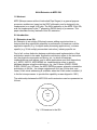
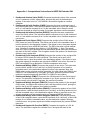
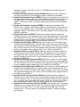
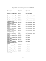
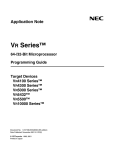
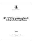
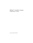
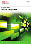
64-bit Extension to MIPS ISA
CSE 3322 Term Paper
Fall 1999
Name
:
Student ID
:
Login ID
:
Submitted
:
Nov 8, 1999
64-bit Extension to MIPS ISA
1.0 Abstract
MIPS (Microprocessor without Interlocked Pipe Stages) is a general-purpose
processor architecture, based on the RISC philosophy and is designed to be
implemented on a single VLSI chip. The 64-bit extension to the MIPS 32-bit ISA,
was first implemented in the 3rd generation R4000 family of processors. This
paper describes the key features of this ISA extension.
2.0 Introduction
2.1 Extension to an ISA
An Extension to an existing ISA simply means adding new instructions or
features that allow significant advances in performance. Extensions could be
application specific (e.g. for digital media processing applications), customer
specific (e.g. 32-bit multiply-accumulate instruction), industry specific etc.
First of all, a clear distinction between architecture and implementation of that
architecture needs to be made. Application architecture refers to the instruction
set, the physical components and timing, etc., to which all hardware
implementations must adhere, and to which applications must limit themselves,
e.g., MIPS I, MIPS II, MIPS MDMX etc. Implementation refers to specific
hardware designs using the architecture, e.g., the R-Series (R2000, R3000,
R4000, R6000, etc). Of these, the MIPS R4000 processor onwards, extends the
architecture to 64 bits – the integer registers and ALU are 64 bits wide, and
linear, 64-bit virtual addressing is available, when the 64-bit mode is enabled. (It
is the first microprocessor to provide this capability as was shipped in 1991.)
The relationship between the MIPS ISA and its extensions can be represented as
follows:
MIPS Extended ISA
MIPS
ISA
Fig 1.1 Extensions to the ISA
2
2.2 64-bit Systems
There are three fundamental requirements a computer system must meet, to be
called a 64-bit system. Firstly, it must have a processor that efficiently supports
64-bit data types including pointers. This implies the primary data paths for the
system is (at least) 64-bits wide. Secondly, there must be a compilation system
that can produce 64-bit executables. And the last requirement is an operating
system that can run 64-bit programs. Thus, it is plain that formulating the 64-bit
ISA, is a first step towards building 64-bit systems.
The emerging applications in the digital consumer market are handheld and palm
PCs, set-top boxes, Web TV, and satellite receivers. The common need in these
applications is finding ways to move data efficiently. According to MIPS
Technologies co-founder John Hennessy, “That’s where a 64-bit RISC
architecture gives you an overwhelming advantage because it provides the
bandwidth you need….. The growth in the level of performance will be much
faster in embedded systems than in general desktop machines.” The first highvolume consumer product to use a 64-bit RISC architecture was the Nintendo-64
video player, which is based on the MIPS R4000 microprocessor!
3.0 A Historical Perspective
The MIPS architecture originated with the MIPS I ISA, the R2000 being the first
microprocessor designed and shipped in the last week of 1985. Till date, this
architecture has been extended in a backward compatible fashion four times.
MIPS II extended MIPS I by providing 32 registers, for double precision math and
adding instructions to give. As applications required 64-bit addressing and data
capability, MIPS III added 64-bit data handling instructions. As processors
became faster due to advances in fabrication and technology, memory latency
became a bottleneck; also, 3-D visualization demanded more floating-point (FP)
performance. MIPS IV added new instructions to boost performance in these
areas. In recent years, however, the huge explosion of 32-bit and 64-bit
processors in embedded and consumer applications and the requirement of
supporting 3D, video, audio have led to the development of more super-set
architectures, like MIPS V for 3D applications and MDMX for digital media.
Another application specific extension is also defined, for cost-sensitive
embedded and consumer applications, MIPS16, announced jointly by LSI Logic
Corporation and MIPS Technologies Inc. are 16-bit instructions geared for having
compressed code. These 16-bit instructions use a lot less memory while
providing the functionality required for the embedded market. Table 1 below, [ref1] summarizes the history of the different ISAs and their respective year of
release.
3
Table 1 - Year of implementation of MIPS processors
ISA
Year
Processors that Implemented ISA
Announced
MIPS I
1984
R2000, R3000
MIPS II
1990
R6000
MIPS III
1991
R4000, R4200, R4300i, R4400, R4600, R4700
MIPS IV
1994
R5000, R8000, R10000 (superscalar processors)
MIPS V
MDMX
MIPS16
1996
1996
1996
TBA
TBA
LSI Logic Tiny RISC
4.0 Hardware Requirements for the 64-bit ISA
The MIPS64 architecture is a superset of the previous MIPS IV and MIPSV
Instruction Set Architectures (ISAs) and incorporates powerful new instructions
specifically for embedded applications as well as proven memory management
and privileged mode control mechanisms. To provide backward compatibility,
every implementation supports two addressing modes. The processor's
addressing mode determines whether it generates 32-bit or 64-bit memory
addresses. It incorporates the best features of previous 32- and 64-bit MIPS
processors, focusing on DSP, data-streaming, embedded applications, and
floating-point arithmetic.
MIPS64 is based on a fixed-length, regularly encoded instruction set, and it uses
a load/store data model. It is streamlined to support optimized execution of highlevel languages. Arithmetic and logic operations use a three-operand format,
similar to the core ISA, allowing compilers to optimize complex expressions
formulation.
4.1 Processor Resources
The CPU provides sixty-four 64-bit wide registers in any MIPS64 implementation.
Thirty-two of these registers, referred to as General Purpose registers (GPR’s)
are reserved for integer operations, while the other thirty-two registers, referred
to as Floating Point General Purpose Registers (FGR’s), are reserved for floating
point operations. The width of these registers depends on the mode of operation.
In 32-bit mode, they are treated as 32 bits wide. In 64-bit mode, they are treated
as 64 bits wide.
In the 32-bit ISA, the FPU has 16 floating-point registers. Each register can hold
either a single-precision (32-bit) or double-precision (64-bit) value. In case of a
double-precision value, $f0 holds the least-significant half, and $f1 holds the
4
most-significant half. All references to these registers in a 32-bit architecture, use
an even register number (for example,$f4, $f8…). But in MIPS64, one can
reference all 32 registers directly. Table 2 summarizes the usage conventions
and restrictions for these registers.
Table 2 – Names and Usage conventions of FGR’s in MIPS64 & MIPS 32.
Register Name
in MIPS64 ISA
Corresponding
MIPS32 Name
Use and Linkage
$f0, $f2
$f0..$f2
Hold results of floating-point type
function
$f1, $f3, $f4..$f11
$f4..$f10
$f12..$f19
$f12..$f14
$f20..$f23
$f16..$f18
Temporary registers, used for
expression evaluation; their values are
not preserved across procedure calls.
Pass single or double precision actual
arguments, whose values are not
preserved across procedure calls
Temporary registers, used for
expression evaluation; their values are
not preserved across procedure calls.
$f24..$f31
$f20..$f30
Saved registers, whose values must be
preserved across procedure calls.
In addition there are a minimum of 6 special purpose registers - PC (program
counter), HI and LO, floating point implementation and control registers FCR0
and FCR31 and a LOAD/LINK (LL) bit. However, unlike MIPS32, in MIPS64
architecture, the PC, HI and LO registers are 64-bits wide. Appendix 1 illustrates
this.
Also, in addition to a 64-bit on-chip FPU, 64-bit integer ALU and 64-bit integer
registers, a processor implementing the MIPS 64-bit architecture should also
provide 64-bit virtual address spaces and a minimum of a 64-bit system bus.
4.2 Data Formats
MIPS64 defines a 64-bit double-word, a 32-bit word, 16-bit half-word and an 8-bit
byte. The byte ordering is configurable in either Big-endian or Little-endian
format, depending on the implementation. e.g. R4300i uses the Little-Endian, and
most of the mainstream processors use Big-Endian. MIPS64 uses 32-bit
addressing and 64-bit data.
5
Data formats are to be used to specify addresses. MIPS CPUs use a byteaddressing scheme. Access to half-words requires alignment on even byte
boundaries, and access to words requires alignment on byte boundaries that are
divisible by four. Access to double words (for 64-bit systems) requires alignment
on byte boundaries that are divisible by eight. In general, any attempt to address
a data item that does not have the proper alignment ( except for “unaligned” load
and store instructions) causes an alignment exception, which is then handled by
the appropriate operating system exception service routine.
4.3 Memory Management Unit
The MMU of an implementation can deploy a Translation Lookup Buffer (TLB) or
a Block Address Translation (BAT) as a virtual-to-physical address translation
mechanism, with the TLB being the most popular. Mapped virtual addresses are
translated into physical addresses using an on-chip TLB1. Designated System
Control Coprocessor (CP0) registers provide the software interface to the TLB.
The processor virtual address can be either 32 or 64 bits wide, depending on
whether the processor is operating in 32-bit or 64-bit mode.
• In 32-bit mode, addresses are 32 bits wide. The maximum user process size
is 2GB (231)
• In 64-bit mode, addresses are 64 bits wide. The maximum user process size
is 1 terabyte (240).
A 32-bit address space can be restrictive for some of today's large database,
engineering, and scientific programs. The 2 GB usable main memory provided to
applications, may not be enough for data intensive applications. A 64-bit address
space may increase data base performance by permitting a huge data cache. A
64-bit engineering or scientific simulation permits problems to be solved that
would otherwise be too large for a 32-bit address space.
The down side of such an advantage is that 64-bit programs have secondary
costs that may increase their memory and cache requirements compared to a
32-bit version. Because pointers are represented as 64-bit values, the memory to
store pointers will double. 64-bit operating systems are very likely to support 64bit file systems. Some application areas like geophysics and particle physics may
require file sizes well in excess of two gigabytes (the general limit for 32-bit file
systems). While 64-bit pointers are manipulated as 64-bit quantities, in the
foreseeable future no machine will use this entire range which could address 16
billion gigabytes of data. Thus, MIPS64 uses 32-bit addressing and 64-bit data.
1
On-chip TLB’s have been implemented in most of the mainstream implementations, including R4400,
R10000 and R8000.
6
4.4 Operating Modes
There exist three operating modes, in which a system implementing the ISA
could operate. These modes, in order of decreasing system privilege are:
•
•
•
Kernel mode (highest system privilege): can access and change any register.
The innermost core of the operating system runs in kernel mode
Supervisor mode: has fewer privileges and is used for less critical sections of
the operating system.
User mode (lowest system privilege): prevents users from interfering with one
another.
Selection between the three modes can be made by the operating system (when
in Kernel mode) by writing into Status register's KSU field. The processor is
forced into Kernel mode when the processor is handling an error (the ERL bit is
set) or an exception (the EXL bit is set).
Appendix 2 shows how the selection of operating modes, instruction sets and
addressing modes are implemented in R10000, by enabling the Status register's
appropriate fields.
4.5 Other Issues
The architecture derives the privileged mode exception handling and memory
management functions from the R4000 and R5000 class processors, which
implemented the MIPS II & III. A set of registers reflects the configuration of the
caches, MMU, TLB, and other privileged features implemented in each core.
The flexibility of high-performance caches and memory management schemes is
a strong feature of the MIPS architecture. The MIPS64 architecture extends this
advantage with well-defined cache control options. The size of the instruction and
data caches can range from 256 bytes to 4Mbytes. The data cache can employ
either a write-back or write-through policy. A no-cache option can also be
specified. With all these features, MIPS 64 is an ISA tailor-made for heavy-duty
data-crunching applications.
5.0 Instruction Classes
In addition to the core instructions of the MIPS32 ISA, each of the instruction
classes have been enriched with new instructions to improve performance. The
five instruction classes of MIPS 64 are similar to MIPS 32 and are given below.
1. Data Transfer – Load and store Instructions
7
2. Computational – Arithmetic and logical operations
3. Jump and Branch Instructions – Change flow of control.
4. Coprocessor Interface - These instructions provide standard interfaces to the
co-processors.
5. Special Instructions - These instructions do miscellaneous tasks.
The most significant instructions of the 64-bit extension in each instruction class
have been dealt with in each of the sections below.
5.1 Extensions to the Data Transfer Instructions
As in MIPS32, load and store are immediate type instructions that move data
between memory and the general registers. However, in MIPS64 instructions are
needed to handle 64-bit data. The additional instructions to do this are listed in
Appendix 3. However, the two very significant integer instructions, which set
MIPS64 apart are Load Linked and Store Conditional. They provide the
mechanism for implementing interprocessor or intertask synchronization
primitives, such as Test-and-Set and Compare-and-Swap.
MIPS 64 architecture also interlocks load instructions, so if an instruction
attempts to use data loaded by the immediately preceding instruction, the
pipeline will stall. In MIPS 32, however, such an attempt will produce an incorrect
result, and a no-op instruction must be added after load unless a useful
instruction not depending on the load can be placed there. The MIPS 64 allows
the no-ops to be eliminated.
The Load linked instruction operates as a standard load instruction but has the
side effect of setting the “link” status bit2. As a part of the cache coherency
mechanism, the processor monitors accesses to the linked location and clears
the link status bit if another processor accesses that location.
Store Conditional performs a store operation only if the link bit is set, and it
provides a register in the destination register indicating if the store was
successful. The two instructions, combined with the hardware mechanism that
controls the link status bit, allow indivisible test-and-set and other semaphore
operations to be implemented without requiring bus locks.
Apart from these two instructions, the Pre-Fetch Instruction also is important. The
"Prefetch" instruction supplies an address and hint to the implementation about
the data. Hints include whether the data is likely to be read or written soon, likely
to be read or written only once, or likely to be read or written many times.
Prefetch does not cause exceptions. This instruction is also used in conjunction
with Branch Likely .
2
The Link status bit is a single bit special purpose register. Refer to Appendix 2.
8
5.2 Extensions to the Computational Instructions
There are general-purpose and coprocessor-specific( e.g., the floating-point coprocessor) computational instructions. Computational instructions perform
arithmetic, logical, shift, Multiply and divide operations on register values.
Fixed-point DSP-type (Digital Signal Processing) instructions further enhances
multimedia processing. These instructions that include Multiply (MUL), Multiply
and Add (MADD), Multiply and Subtract (MSUB), and "count leading 0s/1s,"
previously available only on some 64-bit MIPS processors, provide greater
performance in processing data streams such as audio, video, and multimedia
without adding additional DSP hardware to the system.
All the Arithmetic operations that were supported by the MIPS 32 ISA, have been
extended to operate on 64-bit registers. A comprehensive list, along with
description is provided in Appendix 4.
However, two of the most significant instructions, which have enhanced
efficiency in MIPS64 for handling FP as well as integers are shown in table 3.
Table 3 – MADD and MSUB instructions
Instruction
Operands
Description
MADD
MSUB
1.
2.
3.
4.
destination,
src1,
src2,
src3
1.destination,
2. src1,
3. src2,
4. src3
Multiply the contents of src2 and src3, then
add the result to src1 and store in the
destination register (MADD). The NMADD
instruction does the same multiply then add,
but then negates the sign of the result (This
instruction is for 64-bit values only)
Multiply the contents of src2 and src3, then
subtract the result from src1 and store in the
destination register (MSUB). The NMSUB
instruction does the same multiply then
subtract, but then negates the sign of the
result (This instruction is for 64-bit values
only)
5.3 Jump and Branch Instructions
Jump and branch instructions change the flow of a program. The MIPS 64 ISA
adds conditional Traps and special branch instructions called “likely” to the core
instructions. They are tabulated in Appendix 5.
9
The actual execution order depends on the processor's organization; in a typical
pipelined processor, instructions are executed only in program order. That is, the
next sequential instruction may begin execution during the next cycle, if all of its
operands are valid. Otherwise, the pipeline stalls until the operands do become
valid. Since instructions execute in order, stalls usually delay all subsequent
instructions. A clever compiler can improve performance by re-arranging
instructions to reduce the frequency of these stall cycles.
Although one or more instructions may begin execution during each cycle, each
instruction takes several (or many) cycles to complete. Thus, when a branch
instruction is decoded, its branch condition may not yet be known, as it requires
more information, which will only be available, some time in the future. For faster
execution however, the processor can predict whether the branch is taken, and
then continue decoding and executing subsequent instructions along the
predicted path. When a branch prediction is wrong, the processor must back up
to the original branch and take the other path. This technique is called
speculative execution. Whenever the processor discovers a wrongly predicted
branch, it aborts all speculatively executed instructions and restores the
processor's state to the state it held before the branch. (Side effects, for e.g., the
Cache State not being restored, is possible; but because cache coherency is
maintained, side-effects are harmless in these operations)
Branch prediction can be controlled by the CP0 Diagnostic register. Branch
Likely instructions are always predicted as taken, which also means the
instruction in the delay slot of the Branch Likely instruction will always be
speculatively executed. Since the branch predictor is neither used nor updated
by branch-likely instructions, these instructions do not affect the prediction of
"normal", i.e. the usual conditional branches.
Thus, Branch Likely Instructions are the same as an ordinary branch instruction
(without the "Likely"), except in a branch likely instruction, the instruction
in the delay slot is nullified if the conditional branch is not taken.
5.4 Coprocessor Interface
The Floating-Point Unit is the hardware implementation of Coprocessor 1 in the
MIPS IV Instruction Set Architecture. However, depending on the application and
functionality of the processor, the coprocessor unit could be designed as MDMX,
etc.. The MIPS ISA defines 32 logical floating-point general registers (FGRs), as
mentioned in section 4.1, above. Each FGR is 64 bits wide and can hold either
32-bit single-precision or 64-bit double-precision values. In R10000, the
hardware actually contains 64 physical 64-bit registers in the Floating-Point
Register File, from which the 32 logical registers are taken.
10
The MIPS64 ISA, supports a floating-point condition code register and also
optional paired single-precision floating-point instruction execution (SIMD).
5.5 Special Instructions
The main processor’s special instructions do miscellaneous tasks. Though most
of the following instructions are available in MIPS32, they are a part of the
extension in MIPS64.
1. Break (BREAK) Unconditionally transfers control to the exception handler.
The breakcode operand is interpreted by software conventions. The
breakcode1 operand is used to fill the low-order 10 bits of the 20-bit
immediate field in the BREAK instruction. The optional second operand,
breakcode2 fills the high-order 10 bits.
2. Exception Return (ERET) Returns from an interrupt, exception or error trap.
Similar to a branch or jump instruction, ERET executes the next instruction
before taking effect. (In place of RFE in MIPS32)
3. Move From HI Register (MFHI) Moves the contents of the HI register to a
general-purpose register. Move From LO Register (MFLO) Moves the
contents of the LO register to a general-purpose register.
4. Move To HI Register (MTHI) Moves the contents of a general-purpose
register to the HI register. Move To LO Register (MTLO) Moves the contents
of a general-purpose register to the LO register.
5. Syscall (SYSCALL) causes a system call trap. The operating system
interprets the information set in registers to determine what system call to do.
6.0 Applications of the MIPS64 ISA
Machines with implementation of the 64-bit ISA can operate on data in 64-bit
chunks instead of 32-bit. This results in more efficient processing and permit
programs to utilize huge virtual address spaces. Thus, systems can be designed
to handle enormous files far in excess of two gigabytes. The move to 64-bit
makes workstations more like traditional supercomputers. 64-bit systems make
true supercomputing and hugely data intensive applications feasible on
computers that are more like conventional workstations than highly specialized
and expensive supercomputers. Moreover, 64-bit systems are opening up new
computing possibilities, for e.g., huge-scale databases with sophisticated query
engines, real-time video services and faster and lifelike picture quality.
11
MIPS64 compatible 64-bit MIPS processors are well suited for applications
requiring very high-performance RISC processing and compact, system-on-achip (SOC) implementations3. Some of the areas in which MIPS64 is currently
used are:
Portable Computing Systems
•
•
Handheld and Palm-size PCs including Windows CE Applications
Information Appliances
Network Management
•
•
•
Routers
Switches
xDSL systems
Digital Consumer Devices
•
•
Game Platforms – like the Nintendo 64, Arcade games etc.
Set-top Boxes – for web TV applications
Office Automation
•
•
•
•
Printers
Copiers
Scanners
Multifunction Peripherals
Other
•
•
•
•
•
Industrial Controllers
Automotive Systems
Navigation (GPS) – military uses
Graphics Systems
Dedicated Terminals(POS, ATM, e-cash)
7.0 Conclusion
The megabillion-dollar computer market is always changing. An explosion of
communications technology fueled by the availability of inexpensive and
increasingly powerful RISC microprocessors is leading to increasing use of
embedded computers. Despite the millions of PCs shipped every year,
computers account for less than 10 percent of the total market of microprocessor
and microcontroller chips.
In January, 1999, NEC and Toshiba, two of the world’s leading chip makers,
acquired 64-bit RISC IP by securing 10-year licenses for MIPS Technologies’
Ruby processor4. Ruby, which will be the industry’s first 64-bit RISC to hit 1
3
4
From reference 12
From reference 5
12
billion instructions per second, will serve as an engine for intelligent consumer
devices, including set-top boxes, entertainment products, handheld devices,
Internet appliances, and data communications equipment. The 10-year
agreements are proof that 64-bit applications are real.
Thus, new classes of computer-based devices appear in the market every day.
Most will affect our lives in ways ranging from fun (Nintendo video games) to
significant (like palm top PC’s) to awesome (GPS mapping for computers in new
cars). Behind all this is the MIPS ISA, providing us with the power to efficiently
design complex systems.
13
References
1. MIPS RISC Architecture; Kane, Gerry and Heinrich, Joe; Prentice Hall 1992;
STL QA 76.8.M52K36 1992
2. A Guide to RISC Microprocessors; Slater, Michael; Academic Press; 1992; pp.
146-155; STK TK 7895.M5 G85 1992
3. Is your X code ready for 64-bit? - Mark J. Kilgard; Silicon Graphics Inc.; Oct
1997, http://reality.sgi.com/opengl/64bit/64bit.html
4. MIPSpro Assembly Language Programmer's Guide, MIPS Publications,
Document # 007-2418-001, (http://www.mips.com/publications/index.html)
5. An Interview with John Henessey, Embedded Processor Solutions- A special
issue of Silicon Strategies, Sept, 99 - http://www.s2mag.com/eps/
6. MIPS R4000 Microprocessor User’s Manual; Second Edition; Heinrich, Joe,
MIPS Technologies Publication, 1994.
7. Design of the R8000 Microprocessor, Peter Yan-Tek Hsu, MIPS Technologies,
(http://www.sgi.com/processors/r8000/design/r8000.html#intro)
8.Computer Architecture: Case Studies; Baron, Robert J. and Higbie, Lee;
Addison-Wesley; 1992; pp. 223-232; STL QA 76.9.A73 B3733
9. MIPS V Instruction Set, 1996, Silicon Graphics
(http://www.sgi.com/MIPS/arch/ISA5/#MIPSV_indx).
10.Survey of RISC Architectures; Web Extension I; Computer Organization and
Design: The Hardware/Software Interface, Second Edition; (COD:HSI 2e), by
Patterson, David A. and Hennessy, John L. ;
(ftp://ftp.mkp.com/COD2e/Web_Extensions/survey.htm#I.6)
11. Introduction to MIPS V, Silicon Graphics(http://www.sgi.com/MIPS/arch/ISA5)
12. Product brief on MIPS64 Architecture; MIPS Technologies;
(http://www.mips.com/products/s2p2.html)
14
Appendix 1 - Special Purpose Registers – MIPS 64 ISA
Program Counter (PC)
| 63
32 | 31
PC
0|
Multiply/Divide Registers
| 63
32 | 31
MultHI
0|
MultLO
Floating Point Registers : Impl/Rev (FCR0) & Control/Status (FCR31)
| 31
0|
FCR0
FCR31
Load Linked bit
0
15
Appendix 2 - Implementation of Operating and addressing modes in
R10000
The R10000 has three operating modes and two addressing modes. The three operating modes,
in order of decreasing system privilege are:
• Kernel mode (highest system privilege): can access and change any register. The innermost
core of the operating system runs in kernel mode
• Supervisor mode: has fewer privileges and is used for less critical sections of the operating
system.
• User mode (lowest system privilege): prevents users from interfering with one another.
Selection between the three modes can be made by the operating system (when in Kernel mode)
by writing into Status register's KSU field. The processor is forced into Kernel mode when the
processor is handling an error (the ERL bit is set) or an exception (the EXL bit is set). Table 16-1
shows the selection of operating modes with respect to the KSU, EXL and ERL bits. It also shows
how different instruction sets and addressing modes are enabled by the Status register's XX, UX,
SX and KX bits.
The R10000 processor was designed for use with the MIPS IV ISA; however, for compatibility
with earlier machines, the useable ISAs can be limited to either MIPS III or MIPSI/II.
Table 16-1 Processor Modes
The processor's addressing mode determines whether it generates 32-bit or 64-bit memory
addresses.
•
•
•
In Kernel mode the KX bit allows 64-bit addressing; all instructions are always valid.
In Supervisor mode, the SX bit allows 64-bit addressing and the MIPSIII instructions. MIPS IV
ISA is enabled all the time in Supervisor mode.
In User mode, the UX bit allows 64-bit addressing and the MIPS III instructions; the XX bit
allows the new MIPS IV instructions.
------------
16
Appendix 3 - Load/Store Instructions for MIPS 64 Extended ISA.
1. Load Doubleword (LD) Loads the destination register with the contents of the
doubleword that is at the memory location. The system replaces all bytes of the
register with the contents of the loaded doubleword. The system signals an address
error exception when the effective address is not divisible by eight.
2. Load Linked Doubleword (LLD) Loads the destination register with the contents of
the doubleword that is currently in the memory location. This instruction performs a
SYNC operation implicitly. Load Linked Doubleword and Store Conditional
Doubleword can be used to update memory locations atomically.
3. Load Word Unsigned (LWU) Loads the least-significant bits of the destination
register with the contents of the word (32 bits) that is at the memory location
specified by the effective address. Because the system treats the loaded word as an
unsigned value, it fills the four most-significant bytes of the destination register with
zeros. If the effective address is not divisible by four, the system signals an address
error exception.
4. Load Doubleword Left (LDL) Loads the destination register with the mostsignificant bytes of the doubleword specified by the effective address. The effective
address must specify the byte containing the sign. In a big-endian configuration, the
effective address specifies the lowest numbered byte; in a little-endian machine, the
effective address specifies the highest numbered byte. Only the bytes which share
the same aligned doubleword in memory are merged into the destination register.
5. Load Doubleword Right (LDR) Loads the destination register with the leastsignificant bytes of the doubleword specified by the effective address. The effective
address must specify the byte containing the least-significant bits. In a bid-endian
machine, the effective address specifies the highest numbered byte. In a little-endian
machine, the effective address specifies the lowest numbered byte. Only the bytes
which share the same aligned doubleword in memory are merged into the
destination register.
6. Unaligned Load Doubleword (ULD) Loads a doubleword into the destination
register from the specified address. ULD loads a doubleword regardless of the
doubleword’s alignment in memory.
7. Store Conditional (SC) Stores the contents of a word from the source register into
the memory location specified by the effective address. This instruction implicitly
performs a SYNC operation; all loads and stores to shared memory fetched prior to
the SC must access memory before the SC, and loads and stores to shared memory
fetched subsequent to the SC must access memory after the sc. If any other
processor or device has modified the physical address since the time of the previous
Load Linked instruction, or if an ERET (Exception Return) instruction occurs between
the Load Linked and this store instruction, the store fails. The success or failure of
the store operation (as defined above) is indicated by the contents of the source
register after execution of the instruction. A successful store sets it to 1; and a failed
store sets it to 0. The machine signals an address exception when the effective
address is not divisible by eight.
17
8. Store Doubleword (SD) Stores the contents of a doubleword from the source
register in the memory location specified by the effective address. The effective
address must be divisible by eight, otherwise the machine signals an address error
exception.
9. Store Conditional Doubleword (SCD) Stores the contents of a doubleword from
the source register into the memory locations specified by the effective address. This
instruction implicitly performs a SYNC operation. If any other processor or device has
modified the physical address since the time of the previous Load Linked instruction,
or if an ERET instruction occurs between the Load Linked instruction and this store
instruction, the store fails and is inhibited from taking place. The success or failure of
the store operation (as defined above) is indicated by the contents of the source
register after execution of this instruction. A successful store sets it to 1; and a failed
store sets it to 0. The machine signals an address exception when the effective
address is not divisible by eight.
10. Store Doubleword Left (SDL) Stores the most-significant bytes of a doubleword in
the memory location specified by the effective address. It alters only the doubleword
in memory which contains the byte indicated by the effective address.
11. Store Doubleword Right (SDR) Stores the least-significant bytes of a doubleword in
the memory location specified by the effective address. It alters only the doubleword
in memory which contains the byte indicated by the effective address.
12. Unaligned Store Doubleword (USD) Stores the contents of the source register in a
doubleword specified by the address. The machine does not require alignment for
the storage address.
18
Appendix 4 - Computational Instructions for MIPS 64 Extended ISA
1. Doubleword Absolute Value (DABS) Computes the absolute value of the contents
of src1, treated as a 64-bit signed value, and puts the result in the destination
register. If the value in src1 is –2147483648, the machine signals an overflow
exception.
2. Doubleword Add with Overflow (DADD) Computes the twos-complement sum of
two 64-bit signed values. The instruction adds the contents of src1 to the contents of
src2, or it can add the contents of src1 to the immediate value. When the result
cannot be extended as a 64-bit number, the system signals an overflow exception.
3. Doubleword Add without Overflow (DADDU) Computes the twos- complement
sum of two 64-bit values. The instruction adds the contents of src1 to the contents of
src2, or it can add the contents of src1 to the immediate value. Overflow exceptions
never occur.
4. Doubleword Divide Signed (DDIV) Computes the quotient of two 64-bit values.
DDIV treats src1 as the dividend. The divisor can be src2 or the immediate value. It
puts the quotient in the destination register. If the divisor is zero, the system signals
an error and may issue a BREAK instruction. The DDIV instruction rounds towards
zero. Overflow is signaled when dividing –2147483648 by -1. Note: The special
case DDIV $0,src1,src2 generates the real doubleword divide instruction and leaves
the result in the HI/LO register. The HI register contains the quotient. No checking for
divide-by-zero is performed.
5. Doubleword Divide Unsigned (DDIVU) Computes the quotient of two unsigned 64bit values. DDIVU treats src1 as the dividend. The divisor can be src2 or the
immediate value. It puts the quotient in the destination register. If the divisor is zero,
the system signals an exception and may issue a BREAK instruction. See note for
DDIV concerning $0 as a destination. Overflow exceptions never occur.
6. Doubleword Multiply (DMUL) Computes the product of two values. This instruction
puts the 64-bit product of src1 and src2, or the 64-bit product of src1 and the
immediate value, in the destination register.Overflow is not reported. Note: Use
DMUL when you do not need overflow protection. It is often faster than DMULO and
DMULOU. For multiplication by a constant, the DMUL instruction produces faster
machine instruction sequences than DMULT or DMULTU can produce.
7. Doubleword Multiply (DMULT) Computes the 128-bit product of two 64-bit signed
values. This instruction multiplies the contents of src1 by the contents of src2 and
puts the result in the HI and LO registers. No overflow is possible.
8. Doubleword Multiply Unsigned (DMULTU) Computes the product of two unsigned
64-bit values. It multiplies the contents of src1 and the contents of src2, putting the
result in the HI and LO registers. No overflow is possible.
9. Doubleword Multiply with Overflow (DMULO) Computes the product of two 64-bit
signed values. It puts the 64-bit product of src1 and src2, or the 64-bit product of src1
and the immediate value, in the destination register. When an overflow occurs, the
system signals an overflow exception and may execute a BREAK instruction
10. Doubleword Multiply with Overflow Unsigned (DMULOU) Computes the product
of two 64-bit unsigned values. It puts the 64-bit product of src1 and src2, or the 64-bit
product of src1 and the immediate value, into the destination register. When an
overflow occurs, the system signals an overflow exception and may issue a BREAK
instruction.
11. Doubleword Negate with Overflow (DNEG) Computes the negative of a 64- bit
value. The instruction negates the contents of src1 and puts the result in the
19
destination register. If the value of src1 is –2147483648, the system signals an
overflow exception.
12. Doubleword Negate without Overflow (DNEGU) Negates the 64-bit contents of
src1 and puts the result in the destination register. Overflow is not reported.
13. Doubleword Remainder Signed (DREM) Computes the remainder of the division of
two signed 64-bit values. It treats src1 as the dividend. The divisor can be src2 or the
immediate value. The DREMU instruction puts the remainder in the destination
register. If the divisor is zero, the system signals an error and may issue a BREAK
instruction.
14. Doubleword Remainder Unsigned (DREMU) Computes the remainder of the
division of two unsigned 64-bit values. It treats src1 as the dividend. The divisor can
be src2 or the immediate value. The DREMU instruction puts the remainder in the
destination register. If the divisor is zero, the system signals an error and may issue
a BREAK instruction.
15. Doubleword Rotate Left (DROL) Rotates the contents of a 64-bit register left
(towards the sign bit). This instruction inserts in the least-significant bit any bits that
were shifted out of the sign bit. The contents of src1 specify the value to shift, and
contents of src2 (or the immediate value) specify the amount to shift. If src2 (or the
immediate value) is greater than 63, src1 shifts by src2 MOD 64.
16. Doubleword Rotate Right (DROR) Rotates the contents of a 63-bit register right
(towards the least-significant bit). This instruction inserts in the sign bit any bits that
were shifted out of the least-significant bit. The contents of src1 specify the value to
shift, and the contents of src2 (or the immediate value) specify the amount to shift. If
src2 or the immediate value is greater than 63, src1 shifts by src2 MOD 64.
17. Doubleword Shift Left Logical (DSLL) Shifts the contents of a 64-bit register left
(towards the sign bit) and inserts zeros at the least-significant bit. The contents of
src1 specify the value to shift, and the contents of src2 (or the immediate value)
specify the amount to shift. If src2 (or the immediate value) is greater than 63, src1
shifts by src2 MOD 64.
18. Doubleword Shift Right Arithmetic (DSRA) Shifts the contents of a 64-bit register
right (towards the least-significant bit) and inserts the sign bit at the most-significant
bit. The contents of src2 (or the immediate value) specify the amount to shift. If src2
(or the immediate value) is greater than 63, src1 shifts by src2 MOD 64.
19. Doubleword Shift Right Logical (DSRL) Shifts the contents of a 64-bit register right
(towards the least-significant bit) and inserts zeros at the most-significant bit. The
contents of src1 specify the value to shift, and the contents of src2 (or the immediate
value) specify the amount to shift. If src2 (or the immediate value) is greater than 63,
src1 shifts by src2 MOD 64.
20. Doubleword Subtract with Overflow (DSUB) Computes the twos-complement
difference for two signed 64-bit values. This instruction subtracts the contents of src2
from the contents of src1, or it can subtract the immediate value from the contents of
src1. It puts the result in the destination register. When the true result’s sign differs
from the destination register’s sign, the system signals an overflow exception.
21. Doubleword Subtract without Overflow (DSUBU) Computes the twos complement
difference for two unsigned 64-bit values. This instruction subtracts the contents of
src2 from the contents of src1, or it can subtract the immediate value from the
contents of src1. It puts the result in the destination register. Overflow exceptions
never happen.
20
Appendix 5 - Branch Likely Instructions in MIPS 64
Description
OpCode
Operand
Branch on Equal Likely
BEQL
src1,src2,label
Branch on Greater Than
Likely
Branch on Greater/Equal
Likely
Branch on Greater/Equal
Unsigned Likely
Branch on Greater Than
Unsigned Likely
Branch on Less Than
Likely
Branch on Less/Equal
Likely
Branch on Less/Equal
Unsigned Likely
Branch on Less Than
Unsigned Likely
Branch on Not Equal
Likely
Branch on Equal to Zero
Likely
Branch on Greater/Equal
Zero Likely
Branch on Greater Than
Zero Likely
Branch on Greater or
Equal to Zero and Link
Likely
Branch on Less Than
Zero and Link Likely
Branch on Less/Equal
Zero Likely
Branch on Less Than
Zero Likely
Branch on Not Equal to
Zero Likely
BGTL
src1, immediate, label
BGEL
src1, immediate, label
BGEUL
src1, immediate, label
BGTUL
src1, immediate, label
BLTL
src1, immediate, label
BLEL
src1, immediate, label
BLEUL
src1, immediate, label
BLTUL
src1, immediate, label
BNEL
src1, immediate, label
BEQZL
src1,label
BGEZL
src1,label
BGTZL
src1,label
BGEZALL
src1,label
BLTZALL
src1,label
BLEZL
src1,label
BLTZL
src1,label
BNEZL
src1,label
21