1
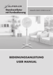
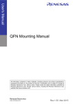
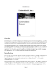
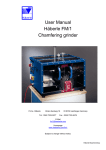
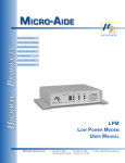
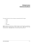
The Empeg and Riōcar Illumination Kit Installation and User’s Manual Last Updated: October 13, 2005 Table of Contents READ THIS FIRST!!! ............................................................................................................................1 Introduction to the Installation Process .................................................................................................3 Install the Hijack Kernel ........................................................................................................................4 Player Disassembly ..............................................................................................................................5 Installing the Button LEDs.....................................................................................................................7 Installing the LED Board .....................................................................................................................11 Final Assembly....................................................................................................................................14 Using the Illumination Kit.....................................................................................................................16 The Empeg And Riōcar Illumination Kit Installation and User’s Manual READ THIS FIRST!!! Thank you for your purchase of the Illumination Kit for the Empeg and RiōCar. READ EVERY WORD OF THIS MANUAL BEFORE PROCEEDING WITH INSTALLATION. We hope you find the installation process both straightforward and rewarding. It is advised that you go over the contents of the package to ensure that there are no missing parts. Bare PCBs of course are exactly that. You will need to purchase your own parts to populate the board. Knob Kits will include: 1 - Bare PCB for LED Illumination 4 - 2x3 mm or 0805 White LEDs 4 - 0603 100 Ohm 1/10W Resistors 1 - 0603 10K Ohm 1/10W Resistors 1 - SOT-23 Transistor, PNP Polarity 2 - Feet Hookup Wire Button Kits will include: 1 - 0603 1K Ohm 1/10W 4 Resistor Pack 4 - 3 mm White LEDs Complete Kits will include: 1 - Bare PCB for LED Illumination 4 - 2x3 mm or 0805 White LEDs 4 - 0603 100 Ohm 1/10W Resistors Labeled “101” 1 - 0603 10K Ohm 1/10W Resistors Labeled “103” 1 - SOT-23 Transistor, PNP Polarity 2 - Feet Hookup Wire 1 - 0603 1K Ohm 1/10W 4 Resistor Pack 4 - 3 mm White LEDs Please take a few moments to familiarize yourself with the installation process to avoid any potential pitfalls. A few things you will need prior to installation: 2.5 mm hex wrench Small tipped Phillips screwdriver Medium tipped Phillips screwdriver Small flat bladed screwdriver Fine tip tweezers Magnifying glass A fine tipped soldering iron 20 – 40 watts Multimeter Electronic solder, 60/40 or 63/37 rosin core should work fine Solder flux (a no clean solution is recommended for least clean up) Isopropyl alcohol Fast drying cyanoacrylate glue (super glue) Hijack kernel +5 volt DC power supply (optional) X-Acto knife with chisel blade (optional) File or electric sander © Eutronix 2003 -2005, All Rights Reserved The Empeg And Riōcar Illumination Kit Installation and User’s Manual 2 DISCLAIMER Installation of this product requires that your Empeg Car or RiōCar be opened. Doing so will automatically void any remaining warranty on the unit. If you are uncomfortable using the above tools, it is highly recommended that you seek assistance from someone at ease with their use. Although every attempt has been made to avoid errors in the installation process, we cannot be held responsible for damage resulting from the improper installation of our products. You assume all risk when installing this product. The procedures depicted herein are merely provided as a guide to installation. What you decide to do is up to you. Proceed at your own risk. You have been warned. A Few Words about this Manual. . . Every effort has been made to provide clear, easy to understand instructions to guide the user through the installation process. We have included many high resolution images to facilitate the process. To get the most out of these images, it is recommended that you print this manual in full color with a high quality photo or laser printer. On to installation. . . © Eutronix 2003 - 2005, All Rights Reserved The Empeg And Riōcar Illumination Kit Installation and User’s Manual 3 Introduction to the Installation Process: The following portion of the manual assumes that you have obtained all necessary components for the illumination circuitry. If you have not purchased a complete kit or the necessary components, please see the component list on the preceding page for the components necessary for your intended application. © Eutronix 2003 -2005, All Rights Reserved The Empeg And Riōcar Illumination Kit Installation and User’s Manual 4 Install the Hijack Kernel STEP 1 – Downloading and installing If you have not already done so, install Mark Lord’s Hijack kernel available at: http://empeg-hijack.sourceforge.net/ according to the instructions at: http://www.riocar.org/modules.php?op=modload&name=FAQ&file=index&myfaq=yes&id_cat=11&categories=Hijack+Kern el+Questions&faqent=177#177 STEP 2 – Setting to max After Hijack is installed, set the button illumination level to “Max,” by holding the volume knob down until the Hijack menu appears. Scroll using the volume knob until “Button Illumination Level” is highlighted. Press the volume knob one time and scroll with the volume knob until “Brightness:” is set to “Max.” © Eutronix 2003 -2005, All Rights Reserved The Empeg And Riōcar Illumination Kit Installation and User’s Manual 5 Player Disassembly STEP 1 - Removing power Disconnect power from the player. Work in a static-free environment by grounding yourself prior to handling the kit parts or any internal components of the player. STEP 2 - Loosening the fascia Locate the four hex bolts on the front of the player. Using a 2.5 mm hex wrench, carefully remove each bolt. STEP 3 - Removing the fascia Grasp the fascia piece by the edges and pull towards the front of the player. STEP 4 - Removing the knob Grasp the knob on the right side of the player and gently tug on it until it comes loose from the encoder shaft to which it is mounted. STEP 5 - Removing the buttons Carefully remove the four buttons located on the left side of the player, putting them aside while keeping them oriented in their installed position inside the player fascia. STEP 6 - Removing the faceplate Remove the faceplate piece by carefully pulling it away from the front of the player. Put it aside, face down in a safe place. If your unit has a factory-installed faceplate, care should be taken not to damage the EMI coating on the backside of the plate. Do not allow ANYTHING to come in contact with this coating. If after removing the player faceplate you discover that any of the hex bolt sockets have come loose, tighten them before proceeding. If any of the hex bolt sockets have become completely separated from the display board. Locate the small lock washers that mount between the hex bolt socket shaft and the display board. They may have fallen out of the player during the disassembly process or may have become lodged inside the player. DO NOT PROCEED UNTIL YOU HAVE LOCATED AND RESECURED ALL LOCK WASHERS ONTO THE DISPLAY BOARD. STEP 7 - Removing the player lid Remove the player lid: Slide the lid forward towards the front of the player until the tabs of the lid meet up with the folded tabs on the body of the player Extend the handle on the front of the player all the way forward to remove the locking arms from the path of the lid Locate a small flat bladed screwdriver and gently pry up on the lid in the location shown to pass the lid over the obstruction in the case while sliding forward. Do this on both sides. © Eutronix 2003 -2005, All Rights Reserved The Empeg And Riōcar Illumination Kit Installation and User’s Manual 6 STEP 8 - Releasing the drive tray Once the player lid has been removed, you should have full access to the player interior. Begin by removing the drive tray screws using a small tipped Phillips screwdriver to remove the four small screws (two per side) on the side of the player. STEP 9 - Removing the drive cable Slide the drive tray back, away from the front of the player and lift up to access the drive cable connector on the player main board. Carefully remove the connector from the player board by pulling it straight up. Do not rock it side to side or the IDE header pins on the player board may become bent. STEP 10 - Removing the display cable Carefully remove the connector from the player board by pulling it straight up. Do not rock it side to side or the display header pins on the player board may become bent. STEP 11 - Releasing the display Remove the four small Phillips screws on the front sides of the player to release the display circuit board. Next, lift the player handle to its fully extended position. Angle the display circuit board at a 45 degree angle towards the front of the player and carefully maneuver it around any obstacle in its path until it is free from the player case. © Eutronix 2003 -2005, All Rights Reserved The Empeg And Riōcar Illumination Kit Installation and User’s Manual 7 Installing the Button LEDs STEP 1 - Locating the resistor pack pads You should now have the display board completely separated of the player. Optional - Separate the foam pads from the VFD display using a chisel bladed X-Acto knife. GENTLY pull the VFD display component forward until it forms a 90 degree angle with the display board as shown below: The foam pads will likely tear if you skipped the optional step above, but they can be fixed later. Once the display has been bent downward, you should be able to locate the resistor pads which are shown below: STEP 2 – Soldering the resistor pack in place This step is by far the most difficult to complete successfully, so please proceed carefully. Thoroughly cover the resistor pads with flux. While you work, keep all materials away from the "103" resistor. Remove the resistor pack from its carrier, being careful not to lose the resistor. Using a low power soldering iron, melt a very small blob of solder onto one of the middle resistor pads on the display board. © Eutronix 2003 - 2005, All Rights Reserved The Empeg And Riōcar Illumination Kit Installation and User’s Manual 8 Using a pair of fine pointed tweezers place the resistor pack over the display board resistor pads so that the edges of the resistor pack align with the pads, as shown below: Using tweezers again, carefully hold the resistor pad in place while remelting the solder previously applied to one of the middle pads. This will serve to hold the resistor pack in place while soldering the remaining pads to the resistor. Proceed with the remaining pads. Apply additional flux as needed. Allow the resistor pack to cool in between solder joints or it may move out of position. You may wish to apply a slight downward pressure on the resistor after each solder joint to assure that it is securely seated on the display board surface. Test for Shorts and Continuity Due to the fine pitch of the pads, it is imperative that you check your work for bridged solder joints. With the VFD component facing away from you, check that there are no shorts between the four resistor elements on the right side of the resistor pack. The left side of the resistor pack (side furthest from the buttons) should have continuity between each contact, so don’t be alarmed when you discover this to be the case; it is as it should be! STEP 3 – Soldering the button LEDs Locate the solder pads on the rear of the display shown below: © Eutronix 2003 - 2005, All Rights Reserved The Empeg And Riōcar Illumination Kit Installation and User’s Manual 9 Using desolder braid and plenty of flux, remove the solder from each of these pads. Clean with isopropyl alcohol. The result should be as shown below: Make the two bends in each of the LED leads as shown below: Bend 1: Bottom View Bend 2 Bottom View Bend 1 Top View Bend 2 Side View © Eutronix 2003 - 2005, All Rights Reserved The Empeg And Riōcar Illumination Kit Installation and User’s Manual 10 Each LED is polarized and will function only in one direction. Insert each LED as shown below: The flat section of each LED should be facing the red bars as pictured above. Position the LEDs as deeply as possible into the buttons without inhibiting their operation. Flip the display board over and solder each LED lead to the LED pad. Clip the excess. STEP 4 – Testing the button LEDs At this point, it is a good idea to test your work. Begin by double checking for shorts. Also, make sure that the LEDs are properly oriented. They will only work in one direction. If all is well, connect the display board to the main board of the player. Leave the VFD bent down for the time being. When connecting the display, be absolutely certain that the connector is installed properly with no misaligned pins. If the connector is not properly installed, you will blow a fuse on the player or worse. Be careful! Once the player has loaded the Hijack kernel loaded earlier, the LEDs installed in the buttons should be lit at maximum level (bright). If no light is seen, unplug and check again for shorts. Make sure you installed the latest Hijack kernel and set the illumination level appropriately. If successful, you may now proceed to installation of the LED board for knob illumination. © Eutronix 2003 - 2005, All Rights Reserved The Empeg And Riōcar Illumination Kit Installation and User’s Manual 11 Installing the LED Board STEP 1 – Test fitting the LED board Due to variations in the relative position of the I/R module and the volume knob shaft, the LED PCB may not fit without slight trimming of the top edge. To determine if trimming of the LED board is necessary, slide the large portion of the volume control shaft (the immobile part) through the hole in the LED board with the silk-screening oriented right-side-up. If the top edge of the board is met with resistance from the I/R module, a SMALL amount of PCB material will need to be removed. SLOWLY and carefully remove material from the top edge of board using a file or electric sander until it can clear the I/R module and lay flat on the metal surface of the volume control rotary encoder. STEP 2 – Assembling the LED board Begin by cleaning the PCB with isopropyl alcohol. Gather all remaining parts. All parts EXCEPT the LEDs are nonpolarized, meaning that they can be installed in either direction. Notice that the PCB has white silkscreen markings on it. These are there to assist in assembling the LED board. Locate the pads labeled “Q1.” This is where the PNP transistor should be soldered. Melt a small amount of solder onto the Q1 pad closest to the Q1 label (the one nearest the large hole in the board). Using a pair of fine tweezers, place the part on the three pads. Carefully holding the transistor in place with slight downward pressure, reheat the solder on the pad until the transistor lead is soldered to the pad. After allowing it to cool, check to make sure the transistor is still properly positioned over the pads. If not, reheat the pad and adjust the position of the transistor. Solder the remaining leads. Locate the pads labeled “R1.” This is where the 10K ohm resistor marker “103” should be soldered. It is the single resistor in the kit. Melt a small amount of solder onto one of the R1 pads. Using a pair of fine tweezers, place the part on the two pads. Carefully holding the resistor in place with slight downward pressure, reheat the solder on the pad until the resistor is soldered to the pad. After allowing it to cool, check to make sure the resistor is still properly positioned over the pads. If not, reheat the pad and adjust the position of the resistor. Solder the remaining side. Locate the pads labeled “R2 - R5.” This is where the four 100 ohm resistors marked “101” should be soldered. They are the four resistors grouped together in the kit. Melt a small amount of solder onto one of each of the individual resistor pads. Using a pair of fine tweezers, place the part on the two pads. Carefully holding the resistor in place with slight downward pressure, reheat the solder on the pad until the resistor is soldered to the pad. After allowing it to cool, check to make sure the resistor is still properly positioned over the pads. If not, reheat the pad and adjust the position of the resistor. Solder the remaining side. Repeat for each resistor. Locate the pads labeled “D1 - D4.” This is where the four white LEDs should be soldered. Note the arrow and the bar in-between the LED pads. This indicates polarity and should be followed closely. Each LED has a notch or colored dot in one corner. This notch or dot must be aligned with the “point” of the arrow and bar in the silkscreen or the blue pads in the picture below. Melt a small amount of solder onto one of each of the individual LED pads. Using a pair of fine tweezers, place the part on the two pads. Make certain that the LED is not positioned over the large hole adjacent to the LED pads. Carefully holding the LED in place with slight downward pressure, reheat the solder on the pad until the LED is soldered to the pad. After allowing it to cool, check to make sure the LED is still properly positioned over the pads. If not, reheat the pad and adjust the position of the LED. Solder the remaining side. Repeat for each LED. © Eutronix 2003 - 2005, All Rights Reserved The Empeg And Riōcar Illumination Kit Installation and User’s Manual Bare LED PCB 12 Assembled LED PCB Finally, attach the hookup wire: - Solder a 6.25 inch (15.9 cm) piece of the included hookup wire to the hole labeled “SGL.” Solder a 2 inch (5.0 cm) piece of the included hookup wire to the hole labeled “PWR.” Solder a 1 inch (2.5 cm) piece of the included hookup wire to the hole labeled “GND.” STEP 3 – Testing the LED board Before installing the LED board, it is advisable to test the board to make certain that you have assembled it properly. If you do not have a 5 volt DC power supply, skip this step. Attach the wires connected to “SGL” and “GND” to the ground portion of a DC power supply. Attach the wire connected to “PWR” to the +5 volt portion of your DC power supply. The LEDs should illuminate brightly. If not, check that the notches in the LEDs (polarity) are correctly positioned and that all components are properly soldered. STEP 4 – Connecting the LED board Route the wire attached to “SGL” behind the VFD component and between the top button housing and the middle two button housing. Then solder the wire to the left lead of the top LED as shown below: © Eutronix 2003 - 2005, All Rights Reserved The Empeg And Riōcar Illumination Kit Installation and User’s Manual 13 Route the wires attached to “PWR” and “GND” to a source of +5 volts DC and ground respectively, such as the pins shown below: STEP 5 – Attaching the LED board Slide the large portion of the volume control shaft (the immobile part) through the hole in the LED board with the silkscreening oriented right-side-up. Make certain that the back of the board rests on the flat metal portion of the volume control rotary encoder. Tuck the hookup wires behind the board and out of the way. Lift the board slightly and apply a few drops of super glue. Apply pressure to the LED board until the glue has set. Once finished, it should look like this: © Eutronix 2003 - 2005, All Rights Reserved The Empeg And Riōcar Illumination Kit Installation and User’s Manual 14 Final Assembly STEP 1 - Repositioning the VFD Begin by applying a small amount of hot melt or other thick bodied glue to the torn pieces of foam tape on the display and VFD halves. Carefully bend the display back into its original position. Be sure the VFD nipple does not come in contact with the LED board. You may wish to push the VFD down slightly from its original position to allow extra room for the VFD nipple. Check to make sure you have left the VFD parallel to the display board. Hold the VFD in position until the glue has set. Power up the player. STEP 2 – Testing the button LEDs Before reassembling your player, test your installation work. Connect the display board to the main board of the player. When connecting the display, be absolutely certain that the connector is installed properly with no misaligned pins. If the connector is not properly installed, you will blow a fuse on the player or worse. Be careful! Once the player has loaded the Hijack kernel loaded earlier, the LEDs installed in the buttons and LED board should be lit at maximum level (bright). If no light is seen, unplug and check again for shorts. Make sure you installed the latest Hijack kernel and set the illumination level appropriately. It should look like this at level 3 brightness: STEP 3 - Reassembly If all went well in the testing phase above, reassemble your player. Internal Assembly Reinstall the drive cable onto the main player board, being careful to maintain the same orientation as the original installation. Avoid misaligning the pins. Secure the drive tray while assuring that each of the DIG-CXXXX output cables remains accessible after securing. The display cable should be installed from step 2 above. © Eutronix 2003 - 2005, All Rights Reserved The Empeg And Riōcar Illumination Kit Installation and User’s Manual 15 External Assembly Fully extend the player handle and slide the player lid right side up so that the label is visible, over the locking tabs until it is secured. Put your choice of light transmitting buttons back into place. Each button including the right and left buttons is unique and will only fit in one location. If viewed from the side, the left button has a larger profile than does the right. Place the player faceplate over the buttons, with the EMI coated side (if applicable) towards the VFD screen. Place your choice of light transmitting knob onto the encoder shaft. Install the fascia. Do not over tighten the bolts. Check to see if the handle binds against the fascia. If so, loosen the four screws display (two per side) pictured on page 3. Apply slight upward pressure to the fascia to move the display board up until the handle no longer binds. © Eutronix 2003 - 2005, All Rights Reserved The Empeg And Riōcar Illumination Kit Installation and User’s Manual 16 Using the Illumination Kit As mentioned earlier, you must have Mark Lord’s hijack kernel to enable the illumination kit. You can set the brightness of the LEDs simply by changing the value in the “Button Illumination Level” option of Hijack. The player will remember two separate brightness levels- one for AC power (home/office use) and one for DC power (mobile application). The white color of the LEDs allows them to backlight any color of button and knob you so choose. In the future, look to Eutronix to provide a myriad of colors. Enjoy your hard work, knowing that you will always be able to locate your buttons and knob in the dark! Known Issues Button and knob lights will flash on occasion during button presses. This is due to the interruption of the PWM function of the PIC microcontroller that controls brightness as well as button commands which are given higher priority in the programming inside the PIC. Thanks to everyone on the Empeg BBS for assisting us. © Eutronix 2003 -2005, All Rights Reserved