1
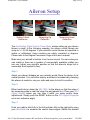
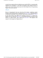
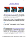
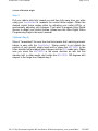
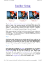
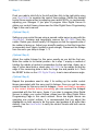
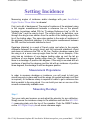
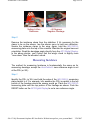
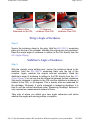
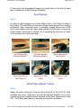
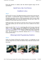
AeroPerfect- User's Manual
Page 1 of 36
User's Manual
AeroPerfect Digital Incidence
& Control Throw Meter
Aileron Setup
Page 2
Elevator Setup
Page 4
Rudder Setup
Page 6
Setting Incidence
Page 8
Degree Conversion
Page 11
Programming Hitec Servos
Page 12
Setting Up Level
Page 23
Frequently Asked Questions
Page 25
Specifications
Page 28
AeroPerfect Warranty
Page 36
file://C:\My Documents\Airplane RC\AeroPerfect Website\aeroperfect_users_manual.html
3/26/2007
AeroPerfect- User's Manual
Page 2 of 36
Aileron Setup
Setting A Zero
Reference
Measuring Up
Deflection
Measuring Down
Deflection
The AeroPerfect Digital Control Throw Meter makes setting up your aileron
throws a cinch! In the following example, the aileron control throws are
setup for +/- 22.35 degrees. If your aircraft's control throws are specified in
inches or millimeters, these numbers are easily converted to degrees.
Please refer to the Degree Conversion Page in this user's manual.
Make sure your aircraft is held so it can't move around. You can make your
own cradle or there are a number of commercially available cradles you
can use. Adjust your aircraft's position so that the aileron's hinge line is
reasonably level (eyeball is fine).
Step 1:
Adjust your aileron linkages as you normally would. Move the aileron to its
neutral position. You can either employ a method of mechanically clamping
the aileron at neutral or use your radio and servo to hold it in position.
Step 2:
Either hand hold or clamp the MU-1800-I to the aileron so that the edge of
the measuring plate is near the hinge line and parallel to it. Place your AP3
Digital Display where you can view it while you make control throw
adjustments. Simply push the RESET button on the AP3 Digital Display to
set a zero reference angle.
Step 3:
Push your radio's stick fully to the left and then fully to the right while using
your AeroPerfect to measure the control throw angles. Obtain the desired
file://C:\My Documents\Airplane RC\AeroPerfect Website\aeroperfect_users_manual.html
3/26/2007
AeroPerfect- User's Manual
Page 3 of 36
control throw angles either by adjusting your radio's EPA's, or mechanically
adjusting your linkages. If you plan to program Hitec Digital Servos to
obtain your control throws, please see the Hitec Digital Servo Programming
Page in this user's manual.
(Step 4)
Since it "remembers" the zero from the first aileron, matching control
throws for the second aileron is easy with the AeroPerfect ! Being careful to
not disturb the position of your aircraft, hand hold or clamp the MU-1800-I
to the other aileron and adjust your linkages until the AP3 reads zero.
(Make sure you orient the MU-1800-I in the same direction as with the first
aileron- in other words, don't rotate the MU-1800-I 180 degrees with
respect to the hinge line). Repeat step 3.
file://C:\My Documents\Airplane RC\AeroPerfect Website\aeroperfect_users_manual.html
3/26/2007
AeroPerfect- User's Manual
Page 4 of 36
Elevator Setup
Setting A Zero
Reference
Measuring Up
Deflection
Measuring Down
Deflection
The AeroPerfect Digital Control Throw Meter makes setting your elevator
control throws a cinch! In the following example, a left elevator half is setup
for +/- 9.55 degrees. If your aircraft's control throws are specified in inches
or millimeters, these numbers are easily converted to degrees. Please refer
to our Degree Conversion Page in this user's manual.
Make sure your aircraft is held so it can't move around. You can make your
own cradle or there are a number of commercially available cradles you
can use. Adjust your aircraft's position so the elevator(s)are reasonably
level (eyeball is fine).
Step 1:
Adjust your elevator linkages as you normally would. Move the elevator to
its neutral position. You can either employ a method of mechanically
clamping the elevator at neutral or use your radio and servo to hold it in
position.
Step 2:
Either hand hold or clamp your AeroPerfect Digital Control Throw Meter to
the elevator so that the edge of the measuring plate is near the hinge line
and parallel to it. It is best to make your measurement as close to the
fuselage as is practical. Place your AP3 Digital Display where you can view
it while you make control throw adjustments. (In order to get the
AeroPerfect AP3 into the photo, it is clamped to a music stand, but you can
place it anywhere within a 6 foot radius from the MU-1800-I for easy
viewing!) Simply push the RESET button on the AP3 Digital Display to set
file://C:\My Documents\Airplane RC\AeroPerfect Website\aeroperfect_users_manual.html
3/26/2007
AeroPerfect- User's Manual
Page 5 of 36
a zero reference angle.
Step 3:
Pull your radio's stick fully toward you and then fully away from you while
using your AeroPerfect to measure the control throw angles. Obtain the
desired control throw angles either by adjusting your radio's EPA's, or
mechanically adjusting your linkages. If you plan to program Hitec Digital
Servos to obtain your control throws, please see the Hitec Digital Servo
Programming Page in this user's manual.
(Optional Step 4)
Since it "remembers" the zero from the first elevator half, matching elevator
halves is easy with the AeroPerfect ! Being careful to not disturb the
position of your aircraft, simply hand hold or clamp the MU-1800-I to the
other elevator half and adjust your linkages until the AP3 reads zero. (Make
sure you orient the MU-1800-I in the same direction as with the first
elevator half- in other words, don't rotate the MU-1800-I 180 degrees with
respect to the hinge line). Repeat step 3.
file://C:\My Documents\Airplane RC\AeroPerfect Website\aeroperfect_users_manual.html
3/26/2007
AeroPerfect- User's Manual
Page 6 of 36
Rudder Setup
Setting A Zero
Reference
Measuring Right
Deflection
Measuring Left
Deflection
The AeroPerfect Digital Control Throw Meter makes setting up your rudder
throws a cinch! In the following example, the rudder control throws are
setup for +/- 28.65 degrees. If your aircraft's control throws are specified in
inches or millimeters, these numbers are easily converted to degrees.
Please refer to our Degree Conversion Page in this user's manual.
Make sure your aircraft is held so it can't move around. You can make your
own cradle or there are a number of commercially available cradles you
can use. Adjust your aircraft's position so that the rudder's hinge line is
reasonably level (eyeball is fine).
Step 1:
Adjust your rudder linkages as you normally would. If your rudder will be
driven by two servos, make sure you attach only the linkages associated
with the servo you're setting up. Move the rudder to its neutral position.
You can either employ a method of mechanically clamping the rudder at
neutral or use your radio and servo to hold it in position.
Step 2:
Either hand hold or clamp the MU-1800-I to the rudder so that the edge of
the measuring plate is near the hinge line and parallel to it. Place your AP3
Digital Display where you can view it while you make control throw
adjustments. (In order to get the AeroPerfect AP3 into the photo, it is
clamped to a music stand, but you can place it anywhere within a 6 foot
radius from the MU-1800-I for easy viewing!) Simply push the RESET
button on the AP3 Digital Display to set a zero reference angle.
file://C:\My Documents\Airplane RC\AeroPerfect Website\aeroperfect_users_manual.html
3/26/2007
AeroPerfect- User's Manual
Page 7 of 36
Step 3:
Push your radio's stick fully to the left and then fully to the right while using
your AeroPerfect to measure the control throw angles. Obtain the desired
control throw angles either by adjusting your radio's EPA's, or mechanically
adjusting your linkages. If you plan to program Hitec Digital Servos to
obtain your control throws, please see the Hitec Digital Servo Programming
Page in this user's manual.
(Optional Step 4)
Setting up your control throws using a second rudder servo is easy with the
AeroPerfect. Unclamp and temporarily remove the MU-1800-I from the
rudder. Rotate your aircraft axially 180 degrees so that the opposite side of
the rudder is facing up. Adjust your aircraft's position so that the hinge line
is reasonably level (again, eyeball is good enough). Disconnect the linkage
from the servo you setup in steps 1 - 3.
(Optional Step 5)
Adjust the rudder linkage for this servo exactly as you did the first one.
Move the rudder to its neutral position. As in step 1, employ a method of
holding the rudder at neutral in preparation for the next step. Again, as in
step 2, either hand hold or clamp your MU-1800-I to the rudder so that the
edge of the measuring plate is near the hinge line and parallel to it. Push
the RESET button on the AP3 Digital Display to set a zero reference angle.
(Optional Step 6)
Repeat the procedure used in step 3 for setting up the rudder control
throws associated with this servo and its linkage. Once you get the same
control throws for this servo and its linkages, (make sure they're operating
in the correct direction before proceeding) you can connect the linkages
associated with the first servo. Again, if you plan to program Hitec Digital
Servos to obtain your control throws, please see the Hitec Digital Servo
Programming Page in this user's manual. Since two digital servos are
operating one control surface, it is recommended that you adjust the
deadbands on both servos to be the same (and perhaps a bit wider than
default). Use the AeroPerfect to verify the control throws with both servos
operating.
file://C:\My Documents\Airplane RC\AeroPerfect Website\aeroperfect_users_manual.html
3/26/2007
AeroPerfect- User's Manual
Page 8 of 36
Setting Incidence
Measuring angles of incidence and/or decalage with your AeroPerfect
Digital Control Throw Meter is a breeze!
First, just a bit of background: The angle of incidence of the airplane's wing
is the angular measurement between a reference line on the plane's
fuselage (sometimes called FRL for "Fuselage Reference Line" or WL for
"Water Line") and the wing's chord. The wing's chord, by definition, runs
through the wing's cross section from the center of the leading edge to the
tip of the trailing edge. The same also applies to the angle of incidence of
the airplane's horizontal stabilizer. It is the angular measurement between
the FRL and the horizontal stabilizer's chord.
Decalage (deka-laj) is a word of French origin and refers to the angular
difference between the wing's chord and the horizontal stabilizer's chord
and does not reference the FRL or WL line. Positive decalage means that
the wing is at a more nose-up angle than the tail. As an example, if the
wing has an incidence of one degree leading edge up and the tail an
incidence of one degree leading edge down (or "negative one degree"),
there is a decalage of positive two degrees. If the wing is mounted with an
incidence of positive five degrees and the tail with an incidence of positive
three degrees, the decalage is still two degrees positive.
Measurement Preparations
In order to measure decalage or incidence, you will need to hold your
aircraft securely in place and level the wings (an eyeball estimate is all that
is required). An incidence clamp is required in order to get a reference line
that is parallel to the wing chord. You can build your own or use one of the
several commercially available ones.
Measuring Decalage
Step 1:
Turn your radio and receiver on and adjust the elevator for zero deflection.
Simply secure the incidence clamp to the stabilizer and hold the MU-1800I's measuring plate onto the top of the crossbar. Push the RESET button
on the AP3 Digital Display to set a zero reference angle.
file://C:\My Documents\Airplane RC\AeroPerfect Website\aeroperfect_users_manual.html
3/26/2007
AeroPerfect- User's Manual
Page 9 of 36
Setting A Zero
Reference
-.60 Degrees
Negative Decalage
Step 2:
Remove the incidence clamp from the stabilizer. If it's necessary for the
clamp to be on the aileron, use the aileron servo to hold zero deflection.
Secure the incidence clamp to the wing. Again, hold the MU-1800-I's
measuring plate onto the top of the crossbar. Maintain the original zero-set
orientation. Read the decalage angle directly from the AP3 Digital Display.
In the above photos, you'll notice that the wing's chord is slightly more
"nose down" than the elevator's chord.
Measuring Incidence
The method for measuring Incidence is fundamentally the same as for
measuring decalage, except the AeroPerfect's zero reference angle is set
at the FRL (or WL).
Step 1:
Identify the FRL (or WL) and hold the edge of the MU-1800-I's measuring
plate parallel to it. For example, let's assume the FRL is parallel to the top
portion of the fuselage where the canopy would go. Place the MU-1800-I's
measuring plate onto the top portion of the fuselage as shown. Push the
RESET button on the AP3 Digital Display to set a zero reference angle.
file://C:\My Documents\Airplane RC\AeroPerfect Website\aeroperfect_users_manual.html
3/26/2007
AeroPerfect- User's Manual
Page 10 of 36
Setting A Zero
Reference on the FRL
-.10 Degrees
Incidence From FRL
.50 Degrees
Incidence From FRL
Wing's Angle of Incidence
Step 2:
Secure the incidence clamp to the wing. Hold the MU-1800-I's measuring
plate onto the top of the crossbar. Maintain the original zero-set orientation.
Read the wing's angle of incidence in relation to the FRL directly from the
AP3 Digital Display.
Stabilizer's Angle of Incidence
Step 3:
With the elevator servo holding zero, secure the incidence clamp to the
stabilizer. Hold the MU-1800-I's measuring plate onto the top of the
crossbar. Again, maintain the original zero-set orientation. Read the
stabilizer's angle of incidence in relation to the FRL directly from the AP3
Digital Display. You can see that the difference between the two incidences
(the wing's incidence in relation to the FRL and the stabilizer's incidence in
relation to the FRL) is .60 degrees. This is exactly what we measured for
the decalage. Obviously, if you're interested in measuring decalage, it is
best to use the method described under "Measuring Decalage" because it
only requires two measurements instead of three.
Take note of where you obtain your zero angle references and notice
whether the angles are moving positive or negative.
file://C:\My Documents\Airplane RC\AeroPerfect Website\aeroperfect_users_manual.html
3/26/2007
AeroPerfect- User's Manual
Page 11 of 36
Degree Conversion
The control throws on many aircraft models are specified in inches or
millimeters. Not to worry- these values are easily converted to degrees! All
you need to know is the control throw distance (as specified in your
model's instructions) and the width (chord) of the control surface at the
point where the control throw distance is specified, again, referring to your
model's instructions. Commonly, control throws are specified at the widest
part of the control surface (the widest where the measurement line is
perpendicular to the hinge line).
Knowing the point where the control throw distance is specified is only
important if the control surface is tapered and does not have a constant
chord. Otherwise, the control throw can be measured (or specified)
anywhere along the length of the control surface.
You can download a Conversion Utility Spreadsheet from the AeroPerfect
Website at http://www.aeroperfect.com/deflection_conversion.xls. You can
"right-click" and select "save target as" or "save link as", depending on your
browser. If your control throws are expressed as a fraction (e.g., 1-5/16),
simply enter "1", then a space, and then "5/16". The spreadsheet will
convert it to a decimal number.
Alternatively, you can divide the deflection which has been expressed in
inches by the control surface width (also expressed in inches). Then, take
the result and push the arcsine button on your calculator. Be sure to use
the same units for the deflection and width.
file://C:\My Documents\Airplane RC\AeroPerfect Website\aeroperfect_users_manual.html
3/26/2007
AeroPerfect- User's Manual
Page 12 of 36
Programming Hitec Servos
Bench Program Your Servo
Because of its high degree of accuracy, the AeroPerfect Digital Control
Throw Meter is extremely useful when programming Hitec Digital servos.
We at Bell Electronic Technologies have developed two methods for
programming Hitec Digital servos using the AeroPerfect Digital Control
Throw Meter: One that is adapted for "on the bench" and one for "on the
plane". The following procedure describes the "on the bench" method.
By using the following procedure, you can bench program your Hitec digital
servos using the Hitec HFP-10 programmer without resorting to the "trial
and error" method. (We are not in any way affiliated with Hitec. We just
wanted to share with you a method that has worked for us!) Please read
our Conditions Of Use below.
Please use the Servo Calibration Spreadsheet along with this procedure.
The spreadsheet is available at http://www.AeroPerfect.com/offplane_cal.xls. Downloading of this spreadsheet indicates that you agree
with the Conditions of Use below. You can either "right-click" and select
"save target as" or "save link as", depending on your browser.
In the following example, a Hitec HS-5645MG is programmed with the
Hitec HFP-10 digital servo programmer. The AeroPerfect Digital Control
Throw Meter is used to accurately measure the angle of the servo arm. The
initial values in the spreadsheet were obtained while using an Eclipse 7
radio with EPA's set to 115%.
Programming Overview
This procedure takes into account the difference (if any) between your
radio's pulse widths and the pulse widths assumed by the HFP-10
programmer for all radios and calculates an appropriate ratio. A preliminary
set of calibration numbers are obtained from the HFP-10 programmer
based on this ratio. These numbers are tested by using your radio and
accurately measuring the servo arm angles with your AeroPerfect Digital
Control Throw Meter. The final programming numbers are then calculated
by the spreadsheet based on the measured angles.
Before we get started, we'd like to say a word about about the direction of
rotation. CW (clockwise) and CCW (counter-clockwise) is mentioned in two
file://C:\My Documents\Airplane RC\AeroPerfect Website\aeroperfect_users_manual.html
3/26/2007
AeroPerfect- User's Manual
Page 13 of 36
contexts within this procedure: One describes which direction the servo
arm is rotating, while the other refers to the direction programmed by the
HFP-10 (Program CW/CCW).
If you program your servo for CW (clockwise servo rotation) using the HFP10, it means that wider pulse widths will cause CW servo rotation.
(Conversely, narrower pulse widths will cause CCW servo rotation). Also, if
you program your servo for CCW (counter-clockwise servo rotation) using
the HFP-10, it means that wider pulse widths will cause CCW servo
rotation. (Conversely, narrower pulse widths will cause CW servo rotation).
On our Eclipse 7 radio (with all of the channels set to "normal" NOT "rev")
we've observed that, with the servo directions set to "normal", that left stick
movement produces narrower pulse widths and down stick movement also
produces narrower pulse widths (and the converse of this is true as well).
Let's get started!
Program Your Radio
Step 1:
Set the trims and sub-trims on all channels of your transmitter to zero and
make sure the EPA adjustments are where you plan to use them (e.g.,
100% or 115%) for all channels. Also, make sure you don't have any mixes
activated. (There is an advantage in setting your EPA's near your radio's
maximum in order to gain resolution. You can even set your radio's EPA's
to maximum, however if you end up needing a greater control throw range,
the servo would have to be reprogrammed.) Set the direction for the radio
channel you plan to use to "Normal".
Measure Your Radio's Pulse Widths
Step 2:
Connect the HFP-10 to the radio channel you plan to use. Select the
Measure Pulse program function. With the control stick at neutral, enter the
number of microseconds into the spreadsheet on the "Measure Radio's
Pulse Widths" row and in the "Middle" column. Move your radio's control
stick in the direction that will yield the smallest pulse width and enter that
value into the spreadsheet on the same row, but in the "CW Degrees"
column. Lastly, move your radio's control stick in the direction that will yield
the largest pulse width and enter that value into the "CCW Degrees"
column.
file://C:\My Documents\Airplane RC\AeroPerfect Website\aeroperfect_users_manual.html
3/26/2007
AeroPerfect- User's Manual
Page 14 of 36
At this point, the spreadsheet shows two scale factors that will be used
later to obtain the "Initial Program Numbers".
Test Fixture
Step 3:
In order to bench program your Hitec Digital servo, you'll need to make a
test fixture. The test fixture is extremely simple since we won't be needing
protractors, tape, machined arms, or pointers. Simply attach one of the
many extra plastic arms you have lying around to a flat piece of wood as
shown below. Not shown in picture, but C-clamping the flat piece of wood
to the workbench is recommended.
Test Fixture Arm
Mounting Detail 1
Test Fixture Arm
Mounting Detail 2
Servo Mounted in
Test Fixture
Servo Mounted in
Test Fixture 2
Overview of Test
Setup
Overview of Test
Setup
Initial Spreadsheet Values
Step 4:
Reset the servo using the Program Reset function on the HFP-10. After
resetting the servo, make sure you set the desired direction of of servo
rotation using the Program cw/ccw function at this time. Please refer to the
CW - CCW discussion above in deciding the direction of rotation.
file://C:\My Documents\Airplane RC\AeroPerfect Website\aeroperfect_users_manual.html
3/26/2007
AeroPerfect- User's Manual
Page 15 of 36
Enter the direction of rotation and the desired angular range into the
spreadsheet.
Install Servo Into Test Fixture
Establish A Zero
Step 5:
Set the HFP-10 to the S-Test Manual program function and set the knob for
the number of microseconds that you measured for neutral in step 2
(Probably somewhere close to 1500 microseconds). Push the servo shaft
into the plastic servo arm of the test fixture so that the servo case is as
parallel to the test fixture servo arm as it can be.
Rotate the knob on the HFP-10 so that the servo case is at your desired
zero angle (where you want the servo arm to be in relation to the servo
case).
Hold one end of the MU-1800-I measuring plate onto the servo case and
obtain a zero angle reference by pushing the reset button on the
AeroPerfect AP3 display (Please utilize the measurement plate for this step
rather than placing the MU-1800-I directly onto the servo case without the
plate. This will prevent any interaction between the MU-1800-I damping
circuit and the servo).
Obtaining Initial Programming Numbers
Step 6:
Select the Program EPAneuFS program function. In preparation for the
next few steps, here are a few more photos that provide an overview of the
test setup:
Step 7
Step 8
Step 9
file://C:\My Documents\Airplane RC\AeroPerfect Website\aeroperfect_users_manual.html
3/26/2007
AeroPerfect- User's Manual
Page 16 of 36
Step 7:
Hold the measuring plate of the AeroPerfect MU-1800-I onto the servo
case and rotate the HFP-10's knob until you reach zero on the AeroPerfect
AP3 display (photo is incorrect and should be showing zero here). Enter
the initial program number from the HFP-10 display into the spreadsheet
under the "(M)" column and on the "Initial Program Numbers" row. Push
the "M" button on the HFP-10.
Step 8:
Continue to hold the measuring plate of the AeroPerfect MU-1800-I onto
the servo case and rotate the HFP-10's knob left until the AeroPerfect AP3
display reads the calculated value from the spreadsheet on the "Initial
Numbers Based On" row (and under the "CW Degrees Column"). Enter the
initial program number from the HFP-10 display into the spreadsheet under
the "UP/L" column (and on the "Initial Program Numbers" row). Press the
UP/L button.
Step 9:
Continue to hold the measuring plate of the AeroPerfect MU-1800-I onto
the servo case and rotate the HFP-10's knob right until the AeroPerfect
AP3 display reads the calculated value from the spreadsheet on the "Initial
Numbers Based On" row (and under the "CCW Degrees Column"). Enter
the initial program number from the HFP-10 display into the spreadsheet
under the "DN/R" column (and on the "Initial Program Numbers" row).
Press the DN/R button.
Measure the Error
Step 10:
Disconnect the servo from the HFP-10 and connect it to your receiver.
Holding the AeroPerfect MU-1800-I measuring plate as described
previously, measure the angles of the servo case as you move the radio's
stick from neutral, to full left and full right. Enter the angular values into the
spreadsheet on the "Measured Angles Using Radio" row. Be sure to enter
the values in either the "CW Degrees" or the "CCW Degrees" column,
depending on which way the servo case is rotating (not whether the
AeroPerfect AP3 is displaying a positive or negative number).
For your radio's neutral stick position, take note of any error from zero. If
the error you measured is that the servo arm is too far CW (Clockwise),
file://C:\My Documents\Airplane RC\AeroPerfect Website\aeroperfect_users_manual.html
3/26/2007
AeroPerfect- User's Manual
Page 17 of 36
enter a positive number into the spreadsheet. Otherwise, if the error you
measured is that the servo arm is too far CCW (Counter-clockwise), enter a
negative number into the spreadsheet. Again, use the "Measured Angles
Using Radio" row and the "Middle" column.
Program the Final Calibration Numbers
Step 11:
The spreadsheet now has the final calibration numbers. Use the Program
EPAneuFS program function to program the "Predicted Numbers" from the
spreadsheet. Rotate the knob until the predicted number for "M" shows on
the HFP-10 display. Push M. Then rotate the knob left until the predicted
number for "UP/L" shows on the display. Push UP/L. Rotate the knob right
until the predicted number for "DN/R" shows on the display. Push DN/R.
Make Final Control Throw Measurements
Step 12:
Disconnect the servo from the HFP-10 and connect the servo to your radio
receiver. Use the AeroPerfect MU-1800-I as before to measure your
desired zero angle and to verify the servo case rotation in both directions.
You have now successfully bench programmed your Hitec digital servo
using your AeroPerfect Digital Control Throw Meter ! You may want to print
out the spreadsheet at this time for future reference.
Servo Programming: "On Your Aircraft"
Here is the second servo calibration procedure developed by Bell
Electronic Technologies. It is adapted to programming a Hitec digital servo
while on the plane. The AeroPerfect Digital Control Throw Meter is
perfectly suited for this because of its high degree of accuracy and ease of
use. This method will allow you to program your Hitec digital servos using
their Hitec HFP-10 programmer without resorting to the "trial and error"
method. (Again, we are not in any way affiliated with Hitec. But this just
works too well to keep it to ourselves!) Please read our Conditions of Use
Below.
Programming Overview
As in the "Bench Program Your Servo", a preliminary set of calibration
file://C:\My Documents\Airplane RC\AeroPerfect Website\aeroperfect_users_manual.html
3/26/2007
AeroPerfect- User's Manual
Page 18 of 36
numbers are obtained from the HFP-10 programmer. A set of estimated
calibration numbers are obtained by multipling the preliminary set of
numbers by a scale factor. The scale factor is calculated based on the ratio
between your radio's actual pulse widths and the HFP-10 programmer's
assumed pulse widths for all radios. Your AeroPerfect Digital Control
Throw Meter is then used to measure your control surface deflection. The
final programming numbers are then calculated by the spreadsheet based
on the measured error.
Please use the following procedure along with the Servo Calibration
Spreadsheet. It can be downloaded at http://www.AeroPerfect.com/onplane_cal.xls Downloading of this spreadsheet indicates that you agree
with the Conditions of Use below. You can either "right-click" and select
"save target as" or "save link as", depending on your browser.
In the following example, a Hitec HS-5645MG is programmed with the
Hitec HFP-10 digital servo programmer while accurately measuring the
control throws with the AeroPerfect Digital Control Throw Meter.
As in the previous procedure, it's best to establish a convention as it relates
to pulse widths and CW - CCW: If you program your servo for CW
(clockwise servo rotation) using the HFP-10, it means that wider pulse
widths will cause CW servo rotation. (Conversely, narrower pulse widths
will cause CCW servo rotation). Also, if you program your servo for CCW
(counter-clockwise servo rotation) using the HFP-10, it means that wider
pulse widths will cause CCW servo rotation. (Conversely, narrower pulse
widths will cause CW servo rotation). On our Eclipse 7 radio we've
observed that, with the servo directions set to "normal", that left stick
movement produces narrower pulse widths and down stick movement also
produces narrower pulse widths (and the converse of this is true as well).
Prepare Your Transmitter
Step 1:
Set the trims and sub-trims on all channels of your transmitter to zero and
make sure the EPA adjustments are where you plan to use them (e.g.,
100% or 115%) for all channels. Also, make sure you don't have any mixes
activated. (There is an advantage in setting your EPA's near your radio's
maximum in order to gain resolution. You can even set your radio's EPA's
to maximum, however if you ever need to increase the control throws, the
servo would have to be reprogrammed.) Set the direction for the radio
channel you plan to use to "Normal".
file://C:\My Documents\Airplane RC\AeroPerfect Website\aeroperfect_users_manual.html
3/26/2007
AeroPerfect- User's Manual
Page 19 of 36
Measure Your Radio's Pulse Widths
Step 2:
Connect the HFP-10 to the radio channel you plan to use. Select the
Measure Pulse program function. With the control stick at neutral, enter the
number of microseconds into the spreadsheet on the "Measure Radio's
Pulse Widths" row and in the "Middle" column. Move your radio's control
stick in the direction that will yield the smallest pulse width and enter that
value into the spreadsheet on the same row, but in the "CW Degrees"
column. Lastly, move your radio's control stick in the direction that will yield
the largest pulse width and enter that value into the "CCW Degrees"
column.
At this point, the spreadsheet shows two scale factors that will be used
later to obtain the "Estimated" program numbers.
Reset Servo and Install Servo Arm
Step 3:
Make sure the servo is NOT connected to any control surfaces. Remove
any servo arms and reset the servo using the Program Reset function on
the HFP-10. After resetting the servo, you may need to reverse the
direction of your servo. If so, use the Program cw/ccw function at this time.
Please refer to the CW - CCW discussion above in deciding the direction of
rotation.
Keep in mind that if you need to change the direction of rotation after your
servo is programmed, the easiest way is to set the corresponding channel
on your radio to "REV". This calibration procedure must be repeated any
time the servo direction is changed using the HFP-10's Program cw/ccw
function.
Step 4:
Set the HFP-10 to the S-Test Manual program function and set the knob for
the number of microseconds that you measured for neutral in step 2
(Probably somewhere close to 1500 microseconds). Push the servo arm
onto the servo shaft 90 degrees to the case (as close as is possible). Make
sure you orient it in the desired direction. (Since there are a finite number
of spline on the servo arm and shaft, it is possible that the angle between
the servo arm and the servo case will not be exactly 90 degrees at this
time. However, that will not affect the accuracy of the servo programming.)
file://C:\My Documents\Airplane RC\AeroPerfect Website\aeroperfect_users_manual.html
3/26/2007
AeroPerfect- User's Manual
Page 20 of 36
Install Servo Into Your Plane
Establish a Zero Reference
Step 5:
If your servo isn't already installed in your aircraft, go ahead and install it
and connect the linkage to the servo arm. Rotate the knob of the HFP-10
so that the servo arm is exactly where you want it (probably 90 degrees to
the servo case). Mechanically adjust linkages so that the control surface is
zero. Establish a zero reference angle by placing the AeroPerfect MU1800-I onto the control surface (that is still set to neutral) and push the
reset button on the AeroPerfect AP3 display.
Obtain Initial Programming Numbers
Step 6:
Select the Program EPAneuFS program function. Decide on the range of
control throw travel and enter it into the spreadsheet on the "Enter Desired
Range" row. Enter the value for both the "CW Degrees" and "CCW
Degrees" columns (The CW and CCW values do not have to be the same).
Step 7:
While holding the AeroPerfect MU-1800-I onto the control surface (the
included clamps and plates work well for this), rotate the HFP-10's knob
until the control surface reaches its neutral position. Enter the initial
program number from the HFP-10 display into the spreadsheet under the
"(M)" column and on the "Initial Program Numbers" row. Push the "M"
button on the HFP-10.
Step 8:
Rotate the HFP-10 knob left until the AeroPerfect AP3 display reads the
desired angle you entered under the "CW Degrees" column on the
spreadsheet on the "Enter Desired Range" row. Enter the initial program
number from the HFP-10 display into the spreadsheet under the "UP/L"
column (and on the "Initial Program Numbers" row). Press the UP/L button.
Step 9:
Rotate the HFP-10 knob right until the AeroPerfect AP3 display reads the
desired angle you entered under the "CCW Degrees" column on the
file://C:\My Documents\Airplane RC\AeroPerfect Website\aeroperfect_users_manual.html
3/26/2007
AeroPerfect- User's Manual
Page 21 of 36
spreadsheet on the "Enter Desired Range" row. Enter the initial program
number from the HFP-10 display into the spreadsheet under the "DN/R"
column (and on the "Initial Program Numbers" row). Press the DN/R
button.
Program the Estimated Numbers
Step 10:
The spreadsheet now holds the "Estimated" program numbers which are
based on two things: The scale factor between your radio's measured
pulse widths and the pulse widths that the HFP-10 assumes for all radios
and the initial program numbers you just entered into the spreadsheet.
Before proceeding, it is imperative that you disconnect any linkage from the
servo arm. Programming the Estimated numbers will require the servo arm
to travel farther than it would under normal operation.
Use the Program EPAneuFS program function as before to program the
"Estimated" numbers into the servo.
Measure the Error
Step 11:
Disconnect the servo from the HFP-10 and connect it to your receiver.
Reconnect your servo arm linkage. Use your AeroPerfect Digital Control
Throw Meter to measure the control throw deflection for each of the stick
positions (neutral, both extremes). Enter the angular values into the
spreadsheet on the "Measured Angles Using Radio" row. Be sure to enter
the values in either the "CW Degrees" or the "CCW Degrees" column,
depending on which direction the servo arm was rotating (not whether the
AeroPerfect AP3 is displaying a positive or negative number).
For your radio's neutral stick position, take note of any error from zero. If
the error you measured is that the servo arm is too far CW (Clockwise),
enter a positive number into the spreadsheet. Otherwise, if the error you
measured is that the servo arm is too far CCW (Counter-clockwise), enter a
negative number into the spreadsheet. Again, use the "Measured Angles
Using Radio" row and the "Middle" column.
Program the Final Calibration Numbers
Step 12:
file://C:\My Documents\Airplane RC\AeroPerfect Website\aeroperfect_users_manual.html
3/26/2007
AeroPerfect- User's Manual
Page 22 of 36
The spreadsheet now has the final calibration numbers. Use the Program
EPAneuFS program function to program the "Predicted Numbers" from the
spreadsheet. Before proceeding, it is imperative that you disconnect any
linkage from the servo arm. The final calibration numbers will require the
servo arm to travel farther than it would under normal operation.
Rotate the knob until the predicted number for "M" shows on the HFP-10
display. Push M. Then rotate the knob left until the predicted number for
"UP/L" shows on the display. Push UP/L. Rotate the knob right until the
predicted number for "DN/R" shows on the display. Push DN/R.
Make Final Control Throw Measurements
Step 13:
Disconnect the servo from the HFP-10 and connect the servo to your radio
receiver. Reconnect any servo arm linkage at this time. Use the
AeroPerfect MU-1800-I to measure and verify the neutral and the control
surface deflection in both directions.
You have now successfully programmed your Hitec digital servo using your
AeroPerfect Digital Control Throw Meter !
Conditions of Use
This calibration procedure and the accompanying servo calibration
spreadsheet are provided by Bell Electronic Technologies "as is". In no
event shall Bell Electronic Technologies be liable for any direct, indirect,
incidental, special, exemplary, or consequential damages arising in any
way from the use of this procedure and/or spreadsheet.
This procedure and spreadsheet are for private use and may not be used
by any other commercial entity. User agrees not to sell this procedure
and/or accompanying spreadsheet. User may freely download and
distribute this procedure and accompanying spreadsheet as long as these
conditions of use are met. User may link to this procedure and/or
spreadsheet.
Any express or implied warranties, including, but not limited to, the implied
warranties of merchantability and fitness for a particular purpose are
disclaimed.
file://C:\My Documents\Airplane RC\AeroPerfect Website\aeroperfect_users_manual.html
3/26/2007
AeroPerfect- User's Manual
Page 23 of 36
Setting Up Level
Because the AeroPerfect Digital Control Throw Meter can be set for any
zero reference angle, relative measurements can be made on your aircraft
without having to reference level (e.g., decalage). However, if desired, the
AeroPerfect can also be used as a level. Here are two methods for
obtaining level:
Method One
Step 1:
Simply place the MU-1800-I on a flat surface so that the insignia is facing
you. Press the AP3 zero button.
Step 2:
Turn the MU-1800-I 180 degrees (insignia facing away from you) and note
the reading on the AP3 Display. Divide that reading in half and write it
down.
Step 3:
Using a few sheets of paper as shims, slip them under the edge of the
measuring plate to obtain the number you wrote down at the end of step 2.
Press the AP3 Zero Button.
You have now calibrated your AeroPefect for level. You can double check
the calibration by comparing measurements with the MU-1800-I "insignia
facing away" and "insignia facing towards you. You should read the same
angle positive (+) as you do negative (-). If the surface on which it sits is
truly level, you will read zero in both directions.
Method Two
Step 1:
If you have a level you can trust, simply place the MU-1800-I onto your
level.
Step 2:
file://C:\My Documents\Airplane RC\AeroPerfect Website\aeroperfect_users_manual.html
3/26/2007
AeroPerfect- User's Manual
Page 24 of 36
Move your level until it reads level. While holding it at that position press
the AP3 Zero Button.
You have now calibrated your AeroPefect for level.
file://C:\My Documents\Airplane RC\AeroPerfect Website\aeroperfect_users_manual.html
3/26/2007
AeroPerfect- User's Manual
Page 25 of 36
Frequently Asked Questions
Question: How can I learn about model aircraft safety?
Answer: The Academy of Model Aeronautics is an excellent resource for
this. Their website can be found here: http://www.modelaircraft.org
Question: Can I use the AeroPerfect to measure my rudder deflection?
Answer: Yes. Since the AeroPerfect's measuring unit uses gravity as a
reference, simply orient your model so that the rudder hinge line is
reasonably parallel (eyeball is good enough) to the floor (fuselage on its
side) for a perfect measurement. See "Rudder Setup" in this user's manual
for details.
Question: When I make a control surface measurement, do the hinge lines
have to be perfectly level or parallel to the floor?
Answer: You can make a perfect measurement without the hinge line being
perfectly level. Just an estimate by eye is all that is needed.
Question: The control throws for my plane are expressed in inches. How do
I convert to degrees?
Answer:
The
conversion
utility
found
here:
http://www.aeroperfect.com/degree.html will allow inches to be converted
to degrees. You may also divide the deflection which has been expressed
in inches by the width (or chord) of the control surface. Then, take the
result and push the arcsine button on your calculator.
Question: How can I use the AeroPerfect to measure control throws when
programming Hitec digital servos?
Answer: See the the "Hitec Digital Servo Programming" page of this user's
manual for a detailed description.
Question: Will the AeroPerfect allow me to match my elevator halves or
match my ailerons?
Answer: Absolutely! The AeroPerfect is perfectly suited for this. See the
"Elevator Setup" and "Aileron Setup" pages in this user's manual for
details.
file://C:\My Documents\Airplane RC\AeroPerfect Website\aeroperfect_users_manual.html
3/26/2007
AeroPerfect- User's Manual
Page 26 of 36
Question: How can I measure wing/stab incidence or decalage with the
AeroPerfect?
Answer: Most modelers who make these measurements already own an
adjustable clamp for this purpose. Simply use your clamp as per its
instructions and place the AeroPerfect on the straight surface for making
measurements. See the "Setting Incidence" page of this user's manual for
details.
Question: Does the AeroPerfect have to be in contact with a control surface
while it's moving from zero to the plus and minus end points?
Answer: There is no need to clamp or hold the AeroPerfect to the control
surface while the control surface is moving. Simply hold the AeroPerfect to
the surface and set zero, then move the surface to its endpoint and hold
the AeroPerfect to the surface and read the angle.
Question: I notice that when the AeroPerfect Meter is sitting on a flat
surface (after resetting unit to zero) and I then turn it 180 degrees, it
appears to show a small error (e.g., 0.3 degrees). Shouldn't the meter read
zero?
Answer: The table is most likely not perfectly level and your AeroPerfect
Meter is measuring the slope of the table. Remember, you do not need to
level your table or aircraft before making measurements. If you desire to
level your table, please refer to the "Setting Up Level" page in this user's
manual for further details about using your AeroPerfect Meter as a
precision level.
Question: Why are there clamps included with the AeroPerfect?
Answer: As an added convenience for adjusting linkages while monitoring
the change in angle and in setting a zero. Caution: Do not rapidly operate
the control surface while the measuring unit is clamped to it.
Question: Is the AeroPerfect compatible with line voltages other than
110VAC?
Answer: Yes, the AP12 Power supply accommodates voltages ranging
from 90 to 264VAC and 47 to 63Hz which accommodates most
international power requirements.
Question: I want to make control throw measurements at my airfield. Will
the AeroPerfect accept a portable, DC power source?
file://C:\My Documents\Airplane RC\AeroPerfect Website\aeroperfect_users_manual.html
3/26/2007
AeroPerfect- User's Manual
Page 27 of 36
Answer: Yes. The AeroPerfect AP3 Display accepts a standard, 2.1
millimeter DIN connector whose center conductor is positive such as Hitec
Tx Charge leads, part #56375 which have red (positive) and black
(negative) banana plugs which can plug into a number of power panels that
supply 12 Volts DC (e.g., Tower Hobbies Tower Power Deluxe Power
Panel or Hobbico Deluxe Power Panel II). Input voltage range is 7.5 - 30
VDC (+12 Volts, D.C. is nominal). Do not connect battery voltage to the
AP3 Display backwards as it will damage the unit. Damage due to
application of reverse polarity is not covered under the terms of the Bell
Electronic Technologies warranty.
Question: Can the AeroPerfect Meter be used as a level?
Answer: Yes, it can be used as a precision level. Please refer to the
"Setting Up Level" page of this user's manual for details.
Question: What if I have a technical question not covered here?
Answer: Please contact our technical support department
questions@AeroPerfect.com if you have additional questions.
file://C:\My Documents\Airplane RC\AeroPerfect Website\aeroperfect_users_manual.html
at
3/26/2007
AeroPerfect- User's Manual
Page 28 of 36
Specifications
MU-1800-I
Technical Description:
The MU-1800-I is a single axis, digital tilt sensor used to report the angle of
an object with respect to gravity. Optical shaft encoder technology provides
a full +/- 180 (360) degree range. A code wheel and an LED light source
comprise the heart of the MU-1800-I. Integral to the MU-1800-I is a weight
which is attached to one side of the code wheel assembly causing it to
remain stationary with respect to gravity. Internal magnetic damping
assures fast response time while eliminating oscillations and ringing. As the
housing moves relative to the codewheel, the moving image of radial lines
is converted to a real-time digital signal.
The MU-1800-I is a non-contacting, rotary to digital converter that converts
real-time shaft angle and direction into a digital signal that is displayed on
the AP3 front panel. It utilizes an extremely rugged mylar disk, LED light
source, metal shaft and high quality ball bearings. The unit is powered by
the AP3 digital display unit, and operates on +5VDC.
The rotary to digital converter uses a transmissive optical encoder module
which has a lensed LED source and a monolithic detector IC enclosed in a
small polymer package. The module uses phased array detector
technology to provide superior performance and greater tolerances over
traditional aperture mask type encoders.
file://C:\My Documents\Airplane RC\AeroPerfect Website\aeroperfect_users_manual.html
3/26/2007
AeroPerfect- User's Manual
Page 29 of 36
Mechanical Drawings:
Front, Back and Side Views
Temperature Ratings:
Operating Temperature Range
Storage Temperature Range
Min
Max
Units
Min
Max
Units
-10
+100
Degrees C
-40
+100
Degrees C
Mechanical Specifications:
file://C:\My Documents\Airplane RC\AeroPerfect Website\aeroperfect_users_manual.html
3/26/2007
AeroPerfect- User's Manual
Page 30 of 36
Vibration 20 g. 5 to 2KHz
Weight
8.47 oz.
Damping:
The MU-1800-I utilizes eddy-current damping technology. Please refer to
the following chart and notice the difference between zero damping and the
MU-1800-I damping (angle measurements are obtained immediately and
without ringing).
AP3 Display
Technical Description:
The AP3 is a digital LCD readout designed to display the incremental count
value of the MU-1800-I. The AP3 features a sign indicator for displaying
both positive and negative angles. Signals from the MU-1800-I are filtered
to ensure signal integrity over the entire input frequency range. The Match
LED illuminates and relay closure occurs when an encoder count equals
the zero angle. Under normal operation the relay closure feature is not
needed. However the modeler may want to connect an external light or
file://C:\My Documents\Airplane RC\AeroPerfect Website\aeroperfect_users_manual.html
3/26/2007
AeroPerfect- User's Manual
Page 31 of 36
audio enunciation indicating zero angle has been reached. Please refer to
the mechanical drawings and electrical specifications for proper
implementation of this feature. Note that any angle reported by the MU1800-I can be reset to a zero reference angle.
The AP3 Digital Display is powered by the AP12, +12 Volt power supply
(included- see below). Optionally, the display unit accepts power from an
external battery through a standard 2.1mm DIN circular plug. (Please see
"Frequently Asked Questions" page in this user's manual for further
details). The AP3 Digital Display supplies the +5 VDC power for the MU1800-I.
Whenever the preprogrammed limits of +/- 0.5 degrees are exceeded, the
AP3 digital display illuminates a corresponding High or Low LED. This
feature is quite useful since it lets the user know when the angle is
approaching zero.
The AP3 is constructed of a lightweight high impact polymer case with a
clear viewing window. The AP3 display offers 0.5" high digits with blue
backlighting. Leading Zero Blanking provides superior readability! (New,
October 2006). The AP3 front panel thickness may range up to a maximum
of 0.125" thick.
Mechanical Drawings:
Back and Side Views
Panel Cutout Drawing
file://C:\My Documents\Airplane RC\AeroPerfect Website\aeroperfect_users_manual.html
3/26/2007
AeroPerfect- User's Manual
Page 32 of 36
Installation Instructions:
Install in a panel with a thickness of up to 0.125".
Cut a rectangle in the panel: 4.79" wide by 2.28" tall.
Remove the 4 screws from the rear of the AP3
Carefully pull apart the case.
Slide the front section of the display into the panel cutout.
Slide the rear cover over the circuitry from the other side of the panel.
Re-install the screws.
Note: It is very important that care be exercised when opening the case. Do
not touch any of the electrical components as static discharge can damage
them. Do not force the AP3 into an undersize cutout or over-tighten the
screws when reinstalling the case. Damage resulting from improper
installation is not covered under the terms of the AeroPerfect Warranty.
file://C:\My Documents\Airplane RC\AeroPerfect Website\aeroperfect_users_manual.html
3/26/2007
AeroPerfect- User's Manual
Page 33 of 36
Electrical Specifications:
Parameter
Min. Typ. Max. Units
Supply Voltage
7.5
-
30
Volts
Supply Current*
-
-
40
mA
Encoder Input Cycle Frequency -
-
1.2
MHz
Relay Contact Rating***
-
-
3.0
Amps
Relay Switching Rating****
-
-
125
24
VAC
VDC
Relay Dielectric Stength
500
-
-
VAC
Relay Contact Resistance
-
-
100
uOhms
Enocder Output Voltage**
4.8
5.0
5.2
VDC
Encoder Supply Current
-
-
250
mA
Encoder Low Input
-
0.4
0.8
VDC
Encoder High Input
2.0
5.0
5.75
VDC
* Without MU-1800-I attached.
** 100mA load.
*** At rated AC or DV voltage.
**** An external clamp diode should be used when switching inductive loads.
AP-12 Power Supply
Description:
The AP-12 is an 18W regulated switching power supply that provides
12VDC @ 1.5A output. The power supply covers voltage inputs ranging
from 90 to 264VAC and 47 to 63Hz which accommodates most
international power requirements. Typical efficiency is 70% and output is
short circuit protected.
The power supply DC output uses a 2.1mm circular plug (center positive)
which is attached to a 48 inch long cable. The power supply plugs directly
into a standard 120VAC receptacle.
Mechanical Drawing:
file://C:\My Documents\Airplane RC\AeroPerfect Website\aeroperfect_users_manual.html
3/26/2007
AeroPerfect- User's Manual
Page 34 of 36
file://C:\My Documents\Airplane RC\AeroPerfect Website\aeroperfect_users_manual.html
3/26/2007
AeroPerfect- User's Manual
Page 35 of 36
Specifications:
Input Voltage
90 to 264VAC
Input Frequency
47 to 63Hz
AC Plug Type
2-Prong, USA Type, non-polarized
Output Voltage
12VDC
DC Output Plug
5.5 x 2.1 x 9.5 mm female barrel, center
positive
Load Regulation
±5%
Ripple & Noise
40mV maximum
Operating
Temperature
0 to 40°C
Storage Temperature
-30 to 80°C
Protections
Over voltage, Over current and Short circuit
Certification
UL 1950, CB (per EN 60950)
EMI
Meets FCC class "B"
AC Input Indicator
Green LED
Size (inches)
3.15 x 2.16 x 1.26 (WLH)
Photograph
file://C:\My Documents\Airplane RC\AeroPerfect Website\aeroperfect_users_manual.html
3/26/2007
AeroPerfect- User's Manual
Page 36 of 36
AeroPerfect Warranty
Bell Electronic Technologies warrants its products against defects in
materials and workmanship for two years from shipment. If Bell Electronic
Technologies receives notice of such defects during the warranty period,
Bell Electronic Technologies will, at its option, either repair or replace
products which prove to be defective, or refund the purchase price upon
prompt authorized return of the product to Bell Electronic Technologies.
Note: This warranty does not apply to defects resulting from: Damage
caused by customer, unauthorized modification or misuse, or operation
outside Bell Electronic Technologies' published specifications for the
product. Under no circumstances will the buyer be entitled to consequential
or incidental damages. Bell Electronic Technologies will not be held
responsible for damages or losses greater than the cost of the original unit.
Flying of model aircraft is a practice that requires a prior knowledge of safe,
prudent flying practices and techniques. Bell Electronic Technologies,
and/or AeroPerfect.com are not responsible for the education of, or
practices by, flyers of model aircraft. The Academy of Model Aeronautics is
an excellent resource for learning about model aircraft safety. Their website
can be found here: http://www.modelaircraft.org
At the discretion of Bell Electronic Technologies, a 15% restocking charge
may apply for cancellations or returns unless due to a manufacturing
defect. A Return Materials Authorization must be obtained before returning
units. Please contact us at questions@AeroPerfect.com to obtain return
authorization. Returns without an authorized RMA number cannot be
accepted.
HAPPY FLYING!
file://C:\My Documents\Airplane RC\AeroPerfect Website\aeroperfect_users_manual.html
3/26/2007