1
Right choice for ultimate yield
LSIS strives to maximize customers' profit in gratitude of choosing us for your partner.
Programmable Logic Controller
XGT IFOS FEnet I/F Module
XGT Series
User’s Manual
XGL-ESHF
Read
this manual carefully before
installing, wiring, operating, servicing
or inspecting this equipment.
Keep
this manual within easy reach
for quick reference.
http://eng.lsis.biz
Safety Instructions
Safety Instructions should always be observed in order to prevent accident
or risk with the safe and proper use the product…
Instructions are separated into “Danger”, “Warning” and “Caution”, and
the meaning of the terms is as follows;
■
Danger
This symbol indicates that serious injury or death may be
caused in a moment if some applicable instructions are
violated.
Warning
This symbol indicates the possibility of serious injury or
death if some applicable instructions are violated.
Caution
This symbol indicates the possibility of slight injury or
damage to products if some applicable instructions are
violated.
The marks displayed on the product and in the user’s manual have the following meanings.
This mark is to call a user's attention to actions and operations which may cause
dangerous situation. Instructions with this mark shall be carefully read and observed
to keep from dangerous situation.
This mark is to call a user's attention to possibility of electric shock under the
special conditions.
■ Safety Instructions when designing
Caution
I/O signal or communication line shall be designed at least 100mm
away from a high-voltage cable or power line to be kept from influence of noise or magnetic
field changing . If not, it may cause abnormal operation.
Let the product installed free from direct vibration if lots of vibration is expected.
Be sure to install the product free from metallic dust which may cause abnormal operation if
lots metallic dust is expected.
■ Safety Instructions when installing
Caution
Use PLC only in the environment specified in general standard. If not, electric shock, fire,
abnormal operation of the product or flames may be caused.
Be sure that the module is correctly secured. If the module is not installed correctly, abnormal
operation, error or dropping may be caused.
■ Safety Instructions when wiring
Caution
Surely use the ground wire of Class 3 for FG terminals, which is exclusively used for PLC. If the
terminals not grounded correctly, abnormal operation may be caused.
Prior to wiring and connection in PLC, check the rated voltage and terminal arrangement of the
product. If other power than rated is connected or wiring is incorrect, it may cause fire or defect.
Secure the screws of terminals tightly with specified torque when wiring. If the screws of terminals
get loose, short circuit or abnormal operation may be caused.
Don’t let any foreign materials such as wiring waste inside the module
■ Safety Instructions for test-operation or repair
Warning
Don’t touch the terminal when powered. Abnormal operation or electric shock may occur.
Prior to cleaning or tightening the terminal screws, let the power off.
Caution
Don’t remove PCB from the module case nor remodel the module. Defect, abnormal operation,
product damage or fire may occur. Prior to installing or disassembling the module, let the power off.
The battery shall be exchanged only when the power is On. If it is exchanged while the power is
Off, the program may be lost.
■ Safety Instructions for waste disposal
Caution
Product waste shall be processed as industrial waste.
Revision History
Version
Data
Remark
Page
V 1.0
’06.07
First Edition
-
V 1.1
’11.05
How to enable link through flag added
CH 5.5.2
Revision history
※ The number of User’s manual is indicated right part of the back cover.
Copyright ⓒ 2005 LSIS Co., Ltd All Rights Reserved.
About User’s Manual
About User’s Manual
Congratulations on purchasing PLC of LSIS Co.,Ltd.
Before use, make sure to carefully read and understand the User’s Manual about the functions,
performances, installation and programming of the product you purchased in order for correct use and
importantly, let the end user and maintenance administrator to be provided with the User’s Manual.
The Use’s Manual describes the product. If necessary, you may refer to the following description and order
accordingly. In addition, you may connect our website(http://www.lsis.biz/) and download the information as a
PDF file.
Relevant User’s Manuals
Title
Description
No. of User’s
Manual
It describes specifications, system structure and EMC
XGK-CPUA/CPUE/CPUH/CPUS
spec. correspondence of CPU module, power module,
10310000508
base, I/O module and increase cable
It describes how to use XG5000 software especially
XG5000 User’s Manual
about online functions such as programming, printing,
10310000512
monitoring and debugging by using XGT series
products.
XGK Series
Instructions & Programming
It is the user’s manual for programming to explain how
to use commands that are used PLC system with XGK
CPU.
10310000510
◎
Chapter 1 Introduction
Contents
◎
---------------------------------------------------------------- 1-1 ~ 1-6
How to Use User’s Manual --------------------------------------------------------------------------- 1-1
Introduction of FEnet Fiber Optic Switch module --------------------------------------------------- 1-2
Features of FEnet Fiber Optic Switch Module ---------------------------------------------------- 1-3
Product Specification ----------------------------------------------------------------------------------------- 1-4
1.4.1 Type ----------------------------------------------------------------------------------------------------- 1-4
1.4.2 No. of modules available by CPU types ------------------------------------------------------- 1-4
1.5 Software for Using the Product ------------ --------------------- ---------------- 1-5
1.5.1 Software checks ------------------------------------------------------------------------------------ 1-5
1.5.2 XG-PD -------------------------------------------------------------------------------------------------- 1-5
1.5.3 Version information --------------------------------------------------------------------------------- 1-6
1.1
1.2
1.3
1.4
Chapter 2 Product Specifications
--------------------------------------------------- 2-1 ~ 2-6
2.1 General Specifications --------------------------------------------------------------------------------------- 2-1
2.2 Performance Specifications --------------------------------------------------------------------------------- 2-2
2.3 Structure and Features --------------------------------------------------------------------------------------- 2-3
2.3.1 Structure of FEnet fiber optic switch module ----------------------------------------- 2-3
2.4 Cable Specification -------------------------------------------------------------------------------------------- 2-6
2.4.1 Optical cable ------------------------------------------------------------------------------------------ 2-6
Chapter 3 Installation and Test Run -------------------------------------------------- 3-1 ~ 3-6
3.1 Cautions in Handling ----------------------------------------------------------------------------------- 3-1
3.1.1 Handling ---------------------------------------------------------------------------------------------- 3-1
3.1.2 Product setting procedure up to the operation ------------------------------------------ 3-2
3.2 Installation ----------------------------------------------------------------------------------------------------- 3-3
3.2.1 Installation of 100BASE-FX ----------------------------------------------------------------------- 3-3
3.3 Test Run -------------------------------------------------------------------------------------------------------- 3-4
3.3.1 Cautions in structuring system ------------------------------------------------------------------- 3-4
3.3.2 Checks before test run ------------------------------------------------------------------- 3-5
3.3.3 Separation/Replacement of module ------------------------------------------------------------ 3-6
Chapter 4 System Structure ------------------------------------------------------------ 4-1 ~ 4-6
4.1 Network System Structure ---------------------------------------------------------------------------------- 4-1
4.1.1 Ring topology structure of FEnet fiber optic switch -------------------------------------- 4-1
4.1.2 Company’s Ethernet system ---------------------------------------------------------------------- 4-2
4.1.3 Ethernet system structure using dedicated network -------------------------------- 4-3
4.1.4 Mixture of dedicated network and other’s Ethernet system ----------------------------- 4-4
4.1.5 Ethernet system of public network and dedicated network ----------------------------- 4-5
4.1.6 Mixture of public network, dedicated network and other’s Ethernet system ------- 4-6
Chapter 5 XG-PD Program
--------------------------------------------------------- 5-1 ~ 5-32
5.1 Introduction ---------------------------------------------------------------------------------------------------- 5-1
5.2 Standard setting ----------------------------------------------------------------------------------------------- 5-2
5.2.1 PLC type setting ------------------------------------------------------------------------------------- 5-2
5.2.2 Register communication module ----------------------------------------------------- 5-3
5.2.3 Standard settings (Module) ----------------------------------------------------------------------- 5-6
5.3 High-speed Link Setting ------------------------------------------------------------------------------ 5-9
5.3.1 Setting High-speed link parameter -------------------------------------------- 5-9
5.4 P2P Setting ----------------------------------------------------------------------------------------------- 5-14
5.4.1 P2P parameter setting ---------------------------------------------------------------------------- 5-14
5.5 Connection and Download for Communication Module ------------------------------------------ 5-16
5.5.1 Download/Upload ---------------------------------------------------------------------------------- 5-16
5.5.2 Enable Link ------------------------------------------------------------------------------------------ 5-20
5.6 System Diagnosis ------------------------------------------------------------------------------------------- 5-24
5.6.1 Execution of diagnosis --------------------------------------------------------------------------- 5-24
5.5.2 Type of diagnosis function ----------------------------------------------------------------------- 5-26
Chapter 6 High-speed Link Service ------------------------------------------------- 6-1 ~ 6-14
6.1 Introduction ----------------------------------------------------------------------------------------------------- 6-1
6.2 High-speed Link Send/Receive Data Processing ------------------------------------------------ 6-2
6.3 Operation Procedure by High-speed Link --------------------------------------------------------------- 6-3
6.4 High-speed Link Parameter Setting ---------------------------------------------------------------------- 6-4
6.4.1 Running XG-PD -------------------------------------------------------------------------------------- 6-4
6.4.2 Standard setting (Module) ------------------------------------------------------------------------- 6-4
6.4.3 High-speed link parameter (High-speed link) ------------------------------------------- 6-5
6.5 High-speed Link Information ------------------------------------------------------------------------------ 6-10
6.5.1 High-speed link flag ------------------------------------------------------------------------------ 6-10
6.5.2 High-speed link information monitoring ----------------------------------------------- 6-12
Chapter 7 P2P Service ----------------------------------------------------------------- 7-1 ~ 7-25
7.1 Introduction ---------------------------------------------------------------------------------------------------- 7-1
7.1.1 Introduction of P2P service ----------------------------------------------------------------------- 7-1
7.1.2 P2P parameter structure --------------------------------------------------------------------------- 7-2
7.2 Type of P2P Service ------------------------------------------------------------------------------------------ 7-3
7.2.1 P2P instruction type ------------------------------------------------------------------------------ 7-3
7.2.2 P2P service ------------------------------------------------------------------------------------------- 7-3
7.3 P2P Service Setting ------------------------------------------------------------------------------------------- 7-4
7.3.1 Ethernet (Server) driver ---------------------------------------------------------------------------- 7-4
7.3.2 P2P channel ------------------------------------------------------------------------------------------ 7-5
7.3.3 Define user frame ----------------------------------------------------------------------------------- 7-9
7.3.4 P2P block -------------------------------------------------------------------------------------------- 7-13
7.4 P2P Service Operation ------------------------------------------------------------------------------------- 7-22
7.5 P2P Diagnosis Function ------------------------------------------------------------------------------------ 7-24
Chapter 8 Dedicated Communication ---------------------------------------------- 8-1 ~ 8-20
8.1 Dedicated Communication --------------------------------------------------------------------------------- 8-1
8.1.1 Introduction ------------------------------------------------------------------------------------------- 8-1
8.1.2 Frame structure -------------------------------------------------------------------------------------- 8-2
8.1.3 Instructions list --------------------------------------------------------------------------------------- 8-4
8.1.4 Data type ---------------------------------------------------------------------------------------------- 8-4
8.2 Running Instruction ------------------------------------------------------------------------------------------- 8-5
8.2.1 Single reading direct variables ------------------------------------------------------------------- 8-5
8.2.2 Continuous reading direct variables ------------------------------------------------------------ 8-8
8.2.3 Single writing direct variables ------------------------------------------------------------ 8-10
8.2.4 Continuous writing direct variables ------------------------------------------------------------ 8-12
8.2.5 Request of status reading (MMI -> PLC) ------------------------------------------------- 8-14
8.3 Dedicated Modbus/TCP server -------------------------------------------------------------------------- 8-19
8.3.1 Driver setting ---------------------------------------------------------------------------------------- 8-19
Chapter 9 Using IFOS Manager ----------------------------------------------------- 9-1 ~ 9-12
9.1 Introduction -----------------------------------------------------------------------------------------------9.2 Functions and Features of IFOS Manager -----------------------------------------------------------9.3 System Environment and Installation -----------------------------------------------------------------9.3.1 System environment ---------------------------------------------------------------------------9.3.2 Installation -------------------------------------------------------------------------------------9.4 Window Description -------------------------------------------------------------------------------------9.4.1 Basic window -----------------------------------------------------------------------------------9.4.2 Detail explanation of menus -------------------------------------------------------------------9.4.3 IFOS status --------------------------------------------------------------------------------------
9-1
9-1
9-1
9-1
9-1
9-2
9-2
9-3
9-5
9.4.4
9.4.5
9.4.6
9.4.7
Rate control-------------------------------------------------------------------------------------- 9-6
Station list---------------------------------------------------------------------------------------- 9-7
Reference packet limit----------------------------------------------------------------------- 9-10
Option ------------------------------------------------------------------------------------------- 9-11
Chapter 10 Troubleshooting ------------------------------------------------------- 10-1 ~ 10-16
10.1 Check by Communication Module LEDs ------------------------------------------------------------- 10-1
10.1.1 Abnormal operation indication ---------------------------------------------------------------- 10-1
10.2 Checking Errors through IFOS Manager------------------------------------------------------------- 10-3
10.2.1 Monitoring RING/BUS Changeover --------------------------------------------------------- 10-3
10.2.2 Warning of defective IFOS module ---------------------------------------------------------- 10-5
10.3 Determining Abnormal Module through XG5000 --------------------------------------------------- 10-6
10.4 Determining Abnormal Module by Error code ------------------------------------------------------- 10-7
10.4.1 Abnormal operation type ---------------------------------------------------------------------- 10-7
10.4.2 Troubleshooting ---------------------------------------------------------------------------------- 10-8
Appendix --------------------------------------------------------------------------------- A-1 ~ A-31
A.1 XGK CPU Memory Device Exhibit ---------------------------------------------------------------------- A-1
A.2 Making Station List using IFOS Manager ------------------------------------------------------------- A-3
A.3 Terms and Definitions ---------------------------------------------------------------------------------------- A-8
A.4 Flag Lists ------------------------------------------------------------------------------------------------------ A-13
A.4.1 Special relay (F) list ------------------------------------------------------------------------------- A-13
A.4.2 Communication relay (L) list ---------------------------------------------------------------------- A-21
A.5 ASCII Code Table ----------------------------------------------------------------------------------------- A-27
A.6 Comparative Table of Ethernet Technology -------------------------------------------------- A-30
A.7 Dimension ----------------------------------------------------------------------------------------------------- A-31
Chapter 1 Introduction
Chapter 1 Introduction
1.1 How to Use User’s Manual
To create a program, refer to the following manuals together.
XGK Series Instruction & Programming User‟s Manual
XGT PLC XG5000 User‟s Manual
The current user‟s manual of XGT FEnet Fiber Optic Switch Module is prepared, based on the following
versions.
XGT PLC XG5000 Programming Tool(Tool): Ver 1.15
XG-PD : Ver 1.4
XGK-CPUH : Ver 1.4
XGK-CPUA : Ver 1.4
XGK-CPUS : Ver 1.4
XGK-CPUE : Ver 1.4
1-1
Chapter 1 Introduction
1.2 Introduction of FEnet Fiber Optic Switch Module
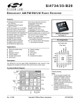
The user‟s manual describes Fast Ethernet Interface of XGT PLC(“FEnet Fiber Optic Switch Module,
100Mbps”). Ethernet is a „technical standard‟ established by a global institution, IEEE. It can control
communication by using CSMA/CD, implement network easily and collect high speed and high capacity
data. FEnet fiber optic switch module is the interface module to transmit data to higher system such as
higher PC or between/among PLCs by using optical media (100BASE-FX).
XGL-ESHF
Fiber Optic Switch Hub
(IFOS Block)
Master
100Base-FX (Fiber Optic)
10/100Base-Tx
10/100Base-Tx
XGL-EFMT
[Fig 1.2.1] System Structure of FEnet Fiber Optical Switch Module
Communication though FEnet Fiber Optic Switch Module is so diverse and it is helpful to refer Chapter 4
System Structure for more information on the system structure and contents.
1) Connecting Ethernet and higher PC(HMI)
2) Data exchange and monitoring between Ethernet PLCs
3) Memory control/trans-reception control of lower device through Ethernet
Remark
1) When structuring FEnet fiber optic switch system, at least, one station out of modules in the
system should be set as the master.
2) When using IFOS Manager, it is necessary to connect Console port of XGL-ESHF to a PC.
3) Station List of IFOS Manager should be connected to Configuration port of the station set as the
master module.
1-2
Chapter 1 Introduction
1.3 Features of FEnet Fiber Optic Switch Module
XGT FEnet fiber optic module supports TCP/IP and UDP/IP protocols and has the following features.
Fast Ethernet (IFOS FEnet I/F module) :
▶ Simply module exchange using module exchange switch of CPU
▶ Module exchange using the module exchange wizard of XG5000
▶ Support EthernetII, IEEE 802.3 standard
▶ Support high speed link for high speed data communication between internal modules
▶ Provide configuration tool(XG-PD) dedicated to communication
▶ Set high speed link block for inter-module link
(max. send 32 blocks x 200 words, max. receive 128 blocks x 200 words, max. trans-receive
128 blocks x 200 words)
▶ Communicate with max. 16 modules save for high speed link(dedicated communication +
P2P communication)
▶ Support Loader service(XG5000) through Ethernet: (dedicated TCP/IP PORT : 2002
assigned)
▶ Simply connect to others‟ module(system) by using P2P communication and XG-PD
(Variable READ/WRITE service available(using Dynamic Connection))
▶ Support 100BASE-FX media
▶ Accessible to system by using public network
▶ Support own protocol(XGT/GLOFA) and others‟ protocol(MODBUS TCP) (dedicated
service)
▶ Support simple client function for communication between own communication modules
and communication with others‟ modules(XGT/GLOFA, modbus TCP P2P client)
▶ Can use ADSL network by supporting dynamic IP
▶ Provide access table for the security of communication with higher PC(HMI)
▶ Support Dynamic Connection/Disconnection using P2P service.
▶ Provide info about various diagnosis, modules and network status
-
CPU module status
Communication module information
communication service(high speed link, dedicated service, P2P) status
AutoScan providing info about own modules connected within a network
Provide PING function to show existence of other modules
Provide info about types of packets received in own communication module and
average amount(estimating network load)
- Provide diagnostics of communication module through network
▶ Provide E-MAIL service(ASCII).
▶ Can mount up to 24 Ethernet communication modules on increased base and basic base.
1-3
Chapter 1 Introduction
1.4 Product Specification
1.4.1 Type
It describes product spec. of XGT FEnet fiber optic switch module.
Type
XGL-ESHF
Description
Remarks
100BASE-FX
Fiber Optic(Multi Mode)
1.4.2 No. of modules available by CPU types
It shows the max number of modules available by CPU types of FEnet fiber optic switch modules. Make
sure to structure a system considering the no. of communication modules.
1) If using XGK
Application
Available communication modules
XGK-CPUH
24 (max. 24 if other communication modules are also installed)
XGK-CPUA
24 (max. 24 if other communication modules are also installed)
XGK-CPUS
24 (max. 24 if other communication modules are also installed)
XGK-CPUE
12 (max. 24 if other communication modules are also installed)
1-4
Chapter 1 Introduction
1.5 Software for Using the Product
It describes major programming tool and other developer‟s software for using FEnet fiber optic switch
module. For more accurate application of program and communication, it is useful to refer to the follows
before applying to the system.
1.5.1 Software checks
1) Applying to XGT
Category
XGL-ESHF
Programming tool
communication setting tool
XG5000
XG-PD
100BASE-FX
Remark
1) The above program is downloadable form the website below. If Internet is not available, it is also
possible to use it from Installation CD-ROM by visiting the close agency.
Internet Website : http://www.lsis.biz
2) XG5000 and XG-PD are programmable through RS-232C port of CPU module and USB. For the
cable type, refer to XGT Catalog Product Exhibit(USB-301A, K1C-050A).
1.5.2 XG-PD
XG-PD is the dedicated communication software supporting basic parameter setting, frame creation and
diagnostics of module and network for the operation of all communication modules including IFOS FEnet
I/F module. For more information, refer to Chapter 5 XG-PD.
The following figure shows the initial window when starting XG-PD.
[Fig 1.5.1] XG-PD Initial Window
1-5
Chapter 1 Introduction
1.5.3 Version information
Before using FEnet fiber optic switch module, check the version of module.
1) Check by XG-PD
It directly connects communication module online to read the info of communication module. During
normal interface with CPU, it can show the following information.
①
②
③
④
⑤
Run XG-PD.
With online connection, connect to CPU.
If connected to CPU, it executes System Diagnosis of XG-PD.
It executes Communication module information in System Diagnosis window.
It shows software info on the right bottom area of Communication module information
window.
[Fig 1.5.2] Checking module‟s version by XG-PD
2) Check by product‟s case label
Each communication module is with module‟s product info on its external case.
If online check is not possible due to absence of any external device interfacing with a PC, it can be
checked after detaching a module.
The rear side has product label showing the product‟s type and version.
1-6
Chapter 2 Product Specifications
Chapter 2 Product Specifications
2.1 General Specifications
It describes the general specifications of XGT series in the below table 2.1.
No.
1
2
3
4
Item
Specifications
Reference
Operating
0 ~ 55 C
-
25 ~ 70 C
-
5 ~ 95%RH, dew should not form
-
5 ~ 95%RH, dew should not form
-
temperature
Storage
temperature
Operating
humidity
Storage
humidity
Intermittent vibration
5
Vibration
-
Frequency
Acceleration
Amplitude
10 f 57Hz
0.075mm
57 f 150Hz
resistance
2
9.8m/s (1G)
-
Times
10 times to
Continuous vibration
each
Frequency
Acceleration
Amplitude
direction of
10 f 57Hz
0.035mm
X, Y and Z
57 f 150Hz
2
IEC61131-2
4.9m/s (0.5G)
Max. impact acceleration: 147 m/s (15G)
2
6
Anti-shock
Authorized time : 11ms
IEC61131-2
Pulse waveform : sine half wave pulse (three times to each direction of X, Y and Z)
Square wave
1,500 V
impulse noise
Static electricity
7
Anti-noise
Voltage : 4kV (contact discharge)
discharge
Emission
27 ~ 500 MHz, 10 V/m
electromagnetic field
Fast transient/
burst noise
8
Internal Test Std of LSIS
IEC61131-2
IEC61000-4-2
IEC61131-2,
IEC61000-4-3
Cate.
Power module
Digital/analog I/O, COM interface
IEC61131-2
Vol.
2kV
1kV
IEC61000-4-4
Environment
Free of corrosive gas and dust
-
9
Altitude
2,000m and lower
-
10
Contamination
2 and lower
-
11
Cooling method
Natural air-cooling type
-
[Table 2.1 General Specification]
Remark
1) IEC(International Electrotechnical Commission)
: An International private institute promoting international cooperation on the standardization of electric/electronic
fields, publishing international specifications and operating the related appropriateness evaluation.
2) Contamination
: As an indicator to represent the contamination of operating environment determining the insulation performance
of a device, contamination 2 means the status with non conductive contamination. However, it may have
temporary conduction depending on dewing.
2-1
Chapter 2 Product Specifications
2.2 Performance Specifications
The following describes the specifications of system structure depending on the media of IFOS FEnet
I/F module. Refer to the table when structuring a system.
Model
Item
Transmission
spec.
General
spec.
XGL-ESHF
(100BASE-FX)
Transfer speed(bitrate)
100Mbps
Transfer method
Base Band
Max. extension between
nods
2km
Max. segment length
-
Max. no. of nods
50/segment
Nod interval
Integer multiple of 0.5m
Max. protocol size
1,500 bytes
Service Area Access
Method
Frame Error Check Method
Current consumption of 5V
side(A)
CSMA/CD
CRC 32
1.2
No. of slot occupied
2
Wt.(g)
220g
[Table 2.2 Performance Specification of IFOS FEnet I/F module]
2-2
Chapter 2 Product Specifications
2.3 Structure and Features
2.3.1 Structure of FEnet fiber optic switch module
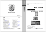
1) XGL-ESHF
XGL-ESHF
MASTER
SLAVE
LOOP
F/DET
STATUS
SPEED1
ACT/L1
R/B
SPEED2
ACT/L2
HS
P2P
PADT
PC
RUN
I/F
LED display
ERR
RESET
Reset switch ▶
100BASE-FX
RX
MODE
Mode switch ▶
MASTER
SLAVE
PORT1
CONFIG
TX
Media connector
RX
Configuration Port ▶
PORT2
TX
XGL-ESHF
2-3
Chapter 2 Product Specifications
① LED indication
Table 2.3.1 describes the Leds of FEnet fiber optic switch module. For determination of troubles by
checking LED status and taking measures, refer to Chapter 10 Troubleshooting.
LED
MASTER
Description
Indicates whether XGL-ESHF module is set as Master. If Switch On, LED is on. If
master is set, master acts as controlling ring.
SLAVE
STATUS
Indicates whether XGL-ESHF module is set as Slave. If Switch Off, LED is on.
Status shows the Live status of XGL-ESHF. In Live, LED flickers every second. Off is
normal status.
R/B
Indicates whether network topology is ring or bus in master module. If ring, LED is on
and slave module indicates changeover status, during which LED is on.
SPD1
Indicates speed of Ring Port1; LED On; 100Mbps, Off: 10MBps
Indicates Link and Act status of Ring Port1.
A/L1
If LED Off, Link On, Off: Link Down, Blinking : Act status
SPD2
Indicates speed of Ring Port2. If LED ON, 100Mbps, OFF: 10MBps
Indicates Link and Act status of Ring Port2.
A/L2
If LED On, Link On, Off: Link Down, Blinking : Act status
LOOP
If a packet is detected to be over Ref. Packet Limit, LED is on.
If it is lower than the packet, LED is off.
F/DET
In case any trouble occurs a next station of network, it is fault; if detected, LED is on.
If error is fixed, LED is off.
As the LED indicating whether FEnet fiber optic switch module works normally after
RUN
being initialized; if normally initialized, LED is on, or if abnormally initialized or
finished, LED is off.
As the LED indicating whether FEnet fiber optic switch module is normally interfaced
I/F
with CPU, it flickers if it is normally interfaced with CPU; if the interface is not normal,
it remains On or Off.
As the LED indicating whether high speed link service is normally working, a user set
the high speed link parameters and if the service is allowed and normally working,
HS
the LED is on.
If high speed link is not allowed even though high speed parameter is set, the service
does not work. A user who uses high speed link service should check whether HS
LED turns on.
2-4
Chapter 2 Product Specifications
(continued)
LED
Description
As the LED indicating whether P2P service is normally working, the LED is on if a
user set P2P parameter, allows P2P service and the service starts.
P2P
If P2P service is not allowed even though P2P parameter is set, P2P service does
not work. A user who uses P2P service should check whether P2P LED turns on.
As the LED indicating whether it is accessed to remote service from a remote
PADT
Ethernet interface COM device(incl. PC), the LED is on if remote service is
connected; if not, it is off.
As the LED indicating whether a remote Ethernet interface COM device(incl. PC)
PC
accesses to the dedicated service, it is on if the service is used; if not, it is off.
The LED indicates any troubles in H/W. If any error is detected, it is on; if no trouble
ERR
is detected, it is off. If ERR LED is on, please contact our A/S center.
[Table 2.3.1 LED description of FEnet fiber optic I/F module]
② Reset Switch
If button is pressed, it resets the entire COM module.
③ Mode Switch
It sets working as master or slave through 2 bits type dip switch.
If bit 1 is on, it works as master while it works as slave if it is off.
④ Configuration Switch
It monitors COM status by IFOS Manager. It can also monitor and detect station’s link and bad
station through Config port connection.
[Fig 2.3.1] indicates cabling diagram for connection.
Config(9 pins)
Connection No. and signal direction
PC
Pin No.
Name
2
RXD
RXD
3
TXD
TXD
5
SG
SG
[Fig 2.3.1] External Connection with a PC
2-5
Name
Chapter 2 Product Specifications
2.4 Cable Specification
2.4.1 Optical cable
Item
Value
Cable type
Twin strands of Multi mode fiber(MMF)
Connector
SC type connector
Fiber optic length
62.5/125um (62.5um fiber optic core and 125um outer cladding)
Length of wave used
1,350 nm
Attenuation
2dB/1,000m and lower
Near-end crosstalk
attenuation
11dB or less
`
Cautions
1) Since connection cable for COM module depends on system structure and environment, make
sure to consult an expert.
2) If fiber optic cable is stained with fingerprint or impurities on its end, it may cause attenuation,
causing troubles of communication.
2-6
Chapter 3 Installation and Test Run
Chapter 3 Installation and Test Run
3.1 Cautions in Handling
3.1.1 Handling
Before installation, check the followings when structuring a system using FEnet fiber optic switch
module.
1) Check the necessary components for system structuring and select the most appropriate
communication module.
2) Select a cable used for the communication module(the only 100BASE-FX is available)
3) When installing the communication module, check whether the base connector is stained with any
impurities are and whether the connector pin of the module is damaged.
4) Every communication module can be mounted on the basic base or extension base but it is
recommended to install on the basic base.
5) When installing the module, make sure to apply appropriate force until the upper part is completely
fastened with the lock of base after inserting the projected part on the bottom of module into the
base groove without communication cable connected. It may have a trouble of interface with CPU
unless lock is not fastened.
6) For the cable for the communication module, the only 100BASE-FX cable may be used and
installed.
7) The cable necessary for the communication with IFOS FEnet I/F module should be standardized
one.
3-1
Chapter 3 Installation and Test Run
3.1.2 Product setting procedure up to the operation
It describes the procedure from installation up to operation. Upon the installation, make sure to install
and set the system in order that it operates in accordance with the following procedure.
Operating procedure
1) Install FEnet fiber optic switch module on base.
2) Connect FEnet fiber optic switch module to other network.
3) Turn off the system.
4) Execute XG-PD and set the basic parameters.
5) Download the basic parameters and reset the module
6) Upon the reset, check whether Module RUN and I/F RUN LED are normal.
7) Once it is checked that LED and CPU are normal, check communication module status info and
CPU info by using diagnostic function of XG-PD.
8) Upon the check whether Module is in normal status, check whether it sends response by using
ping from PC to network in order to check network connection or check it by using live check
items in the diagnostic service of XG-PD unless PC is not connected to a PC.
9) Set the communication service and download it.
10) Allow the communication service link.
11) After creating a program using XG5000, write it to CPU and start operating.
Remark
1) Remember to reset the module once the station number and IP address are set by software.
Also, make sure to maintain the values read from communication module when initializing
the first station number and IP address(incl. frame). Any changes during communication are
not applied during operation.
3-2
Chapter 3 Installation and Test Run
3.2 Installation
3.2.1 Installation of 100BASE-FX
SC type multi mode
[Fig 3.2.1] How to install 100BASE-FX
The max. segment length of 100BASE-FX is 2km(a distance between the module and optical
switch). Cross-connect Tx of module to Rx of optical switch and Rx of module to Tx of optical
switch.
주Caution
1) During handling optical cable, note that it is vulnerable to impact, pressure, bend and
pulling.
If any contact side between optical cable of connector and cable end is contaminated, it
may cause trouble in communication or make the communication impossible.
2) In case it is installed outside, it needs to take an additional measure, suitable for the
installation environment, to protect cable.
3-3
Chapter 3 Installation and Test Run
3.3 Test Run
Upon communication cabling work, power it on, check LED operations whether they work normally
and if normal, download the program to PLC by using XG5000 and execute the program.
3.3.1 Cautions in structuring system
1) IP address including the module should be different one another. If any duplicate address is
connected, it may cause a trouble, interfering with normal communication. In addition, to use
HS link service, HS link station number of all stations should be different with hat of other
station.
2) Make sure to use the only specified std cable. Using any other cable unspecified may cause a
trouble of communication.
3) Before installing, it is important to check if any cable is disconnected or short-circuited.
4) Fasten the cable connection by completely tightening communication cable. Any loose cable
connection may cause a serious trouble of communication.
5) If communication cable is connected long distantly, make sure to cable it far way from power
cable or inductive noise.
6) Because of little flexibility, coaxial cable should be bifurcated, at least, 30cm lower from
connection in a communication module; if the cable is bent at a right angle or forcibly
transformed, it may cause cable disconnection or destruction of connector in a communication
module.
7) If LED works abnormally, refer to ‘Chapter 10 Troubleshooting’ of the user’s manual to check
potential causes and take measures; if the symptom continues even after taking measures,
contact the customer service center.
3-4
Chapter 3 Installation and Test Run
3.3.2 Checks before test run
It describes checks before test running communication module.
1) Communication module installed on PLC
Checks
Description
Installation and checklist of basic S/W
- Is the installation and operation of XG5000 well?
- Is the execution and operation of XG-PD well?
Communication cable connection
(as long as cable is connected)
- Is communication cable well connected and is tab well used?
- Are the module LED and cable connection normal?
Module installation
- Is communication module correctly installed on basic base?
2) Test Run Procedure
It describes the steps up to test run just after installation of PLC.
Start
Power on :
① Check input power
② Check communication cable connection
③ Power it on.
④ Check whether Power LED of Power module is on
⑤ Check the LED status of CPU module
-> In case of abnormality, refer to the ‘troubleshooting’ of each PLC manual.
⑥ Check whether LED status of communication module is normal
-> If abnormal, refer to the ‘Chapter 10 Troubleshooting’ of the manual.
⑦ Set system parameters accurately and download them.
▼
Programming: programming in XG5000 and write it to CPU module.
▼
Sequence check:
Check the operation of communication module in accordance with program.
▼
Program modification:
If any trouble occurs in sequence program, modify it.
▼
Program reservation:
① Save it in USB memory or HDD.
② Print circuit diagram and its lists.
③ If required, save a program in memory module.
Completion
3-5
Chapter 3 Installation and Test Run
3.3.3 Separation/Replacement of module
If it is necessary to replace or remove a module owing to h/w error or system change, handle
the module in accordance with the following procedure.
1) Procedure to replace communication module
(1) Turn off the base on which communication module is installed.
(2) Separate network cable and connector.
(3) Operate and install a module in accordance with 3.3.2 setting procedure.
2) Communication module replacement using the module replacement switch of CPU.
Refer to the directions of CPU module replacement switch.
3) Communication module replacement using XG5000 module replacement wizard
Refer to the module replacement wizard of XG5000.
Remark
1) To replace FEnet fiber optic switch module, please reset the counterpart device(HMI or PC) or,
it may cause no response from the device or cancellation of communication, making the
communication impossible.
3-6
Chapter 4 System Structure
Chapter 4 System Structure
4.1 Network System Structure
4.1.1 Ring topology structure of FEnet fiber optic switch
Ring and bus topology can be structured only with FEnet fiber optic switch module and it is also possible to
monitor topology in real time by using the dedicated software, IFOS Manager on a PC.
PLC [A]
IP: 192.168.91.188
Master
PLC [B]
IP: 192.168.91.189
PLC [C]
IP: 192.168.91.190
Optic
Cable
RS232
PLC [D]
IP: 192.168.91.191
PLC [E]
IP: 192.168.91.192
PC
[Fig4.1.1] Ring Topology using FEnet Fiber Optic Switch Module
Remark
1) In structuring FEnet fiber optic switch module system, one station, at least, should be set as
master.
2) For use of IFOS Manager, a PC should be connected to Console Port of XGL-ESHF.
3) Station list of FEnet fiber optic switch module should be connected to the config port of FEnet set
as the master.
4-1
Chapter 4 System Structure
4.1.2 Company’s Ethernet system
A company’s Ethernet system may be connected to Internet public network by using an open type protocol,
TCP/IP. Therefore, it is possible to access to the field PLC system on net by using GLOFA VIEW of the wide
area monitoring system[1,2] in Fig [4.1.2]. In addition, it is also possible to approach the field PLC system
only with the local monitoring system directly connected the field network.
Wide area monitoring system [1] Wide area monitoring system [2]
IP:191.100.105.1
IP:191.100.105.2
GLOFA
VIEW
GLOFA
VIEW
Hub
Router or
Gate way
Internet
Router or
Gateway
PLC [A]
IP: 192.168.91.188
PLC [B]
IP: 192.168.91.189
Fiber Optic
Switch Hub
(IFOS Block)
PLC [C]
IP: 192.168.91.190
Master
Fiber Optic
Switch Hub
(IFOS Block)
Local monitoring
system [1]
IP:192.168.91.194
Local monitoring
system [2]
IP:192.168.91.195
GLOFA
VIEW
[Fig 4.1.2] Company’s Ethernet System
4-2
Chapter 4 System Structure
4.1.3 Ethernet system structure using dedicated network
Ethernet system can be structured by using a common network, that is, dedicated network that is not
connected to Internet network. Fig 4.1.3 shows an example of Ethernet system structure using a dedicated
network. Each PLC system connects the dedicated network’s Ethernet network using XGT Ethernet module
while PLC system connected to the dedicated network Ethernet may receive or send data by using mutual
HS link, P2P, dedicated service and etc.
PLC [A]
IP: 192.168.91.188
PLC [B]
IP: 192.168.91.189
PLC [C]
IP: 192.168.91.190
Master
Fiber Optic
Switch hub
(IFOS Block)
GLOFA
VIEW
Higher system
IP: 192.168.91.193
PLC [D]
IP: 192.168.91.191
PLC [E]
IP: 192.168.91.192
[Fig4.1.3] Ethernet System(dedicated network)
4-3
Chapter 4 System Structure
4.1.4 Mixture of dedicated network and other’s Ethernet system
Figure 4.1.4 shows an example of dedicated network Ethernet system structured by using a company’s
PLC system and other’s PLC system. A company’s Ethernet module allows user-defined communication.
Therefore, it is necessary to know other’s PLC Ethernet module’s frame structure to make is possible to
send and receive data from/to a company’s PLC and other’s PLC by using user-defined communication.
PLC [A]
IP: 192.168.91.188
Fiber Optic
Switch Hub
(IFOS Block)
PLC [B]
IP: 192.168.91.189
PLC [C]
IP: 192.168.91.190
Master
GLOFA
VIEW
Higher system
IP: 192.168.91.193
Other’s PLC [D]
IP: 192.168.91.191
PLC [E]
IP: 192.168.91.192
[Fig4.1.4] Ethernet System(dedicated network + others)
4-4
Chapter 4 System Structure
4.1.5 Ethernet system of public network and dedicated network
A company’s Ethernet system can be connected to a public Internet network by using an open type
protocol, TCP/IP. Therefore, it is possible to approach to the field PLC system through Internet by GLOFA
VIEW of the wide area monitoring system[1,2] in Fig [4.1.5]. In addition, it is also possible to approach to the
field PLC system only with the local monitoring system directly connected the field network.
Wide area
monitoring system[1]
IP:191.100.105.1
GLOFA
VIEW
Wide area
monitoring system [2]
IP:191.100.105.2
GLOFA
VIEW
Hub
Router or
Gateway
Internet
Router or
Gateway
PLC [A]
IP: 192.168.91.188
PLC [B]
IP: 192.168.91.189
Fiber Optic
Switch hub
(IFOS Block)
PLC [C]
IP: 192.168.91.190
Master
Fiber Optic
Switch hub
(IFOS Block)
Local monitoring
system[1]
IP:192.168.91.194
Local monitoring
system[2]
IP:192.168.91.195
GLOFA
VIEW
[Fig 4.1.5] Ethernet System (public network + dedicated network)
4-5
Chapter 4 System Structure
4.1.6 Mixture of public network, dedicated network and other’s Ethernet system
Figure 4.1.6 shows a mixed Ethernet network system in which a company’s PLC system and other’s PLC
system are mixed by using Internet, that is, public network and dedicated network. The wide area monitoring
system[1, 2] may approach to a remote Ethernet network by using public network. The wide area monitoring
system approaching to a remote Ethernet network may receive or send necessary data by approaching to a
company’s PLC and other’s PLC. In addition, it is also possible to approach to the field PLC system only with
the local monitoring system directly connected the field network.
Wide area monitoring
system [1]
IP:191.100.105.1
GLOFA
VIEW
Wide area monitoring
system [2]
IP:191.100.105.2
GLOFA
VIEW
Hub
Router or
Gateway
Internet
Router or
Gateway
PLC [A]
IP: 192.168.91.188
PLC [B]
IP: 192.168.91.189
Fiber Optic
Switch Hub
(IFOS Block)
PLC [C]
IP: 192.168.91.190
Master
Fiber Optic
Switch Hub
(IFOS Block)
GLOFA
VIEW
Local monitoring
system [1]
IP:192.168.91.194
Local monitoring
system [2]
IP:192.168.91.195
Other’s PLC [D]
IP: 192.168.91.191
[Fig 4.1.6] Ethernet System (public network + dedicated network + others)
4-6
Chapter 5 XG-PD Program
Chapter 5 XG-PD Program
A user can set or change types of parameters by using the network integration software, XG-PD in
order to operate FEnet fiber optic switch module.
XG-PD is the dedicated Communication module setting tool to set or control system parameters,
service selection, parameter preparation, frame information and etc of the communication module.
5.1 Introduction
As a basic program tool to control and manage network in Ethernet communication, it can set and manager
everything about Communication module such as system parameter, service parameter, module and
network diagnosis.
Regarding Ethernet network, XG-PD can be classified as follows.
1) Communication system basic parameter setting
2) Communication service(high speed link, P2P, dedicated service) parameter setting
3) Module/Network diagnostics service
It is possible to write(download) parameter and files set by a user to Ethernet Communication module
through CPU module. Since Communication system parameter downloaded once is managed by CPU, it
can be immediately used without re-setting even though a new Communication module is installed.
The chapter mainly focuses on the settings necessary when using Ethernet module.
5-1
Chapter 5 XG-PD Program
5.2 Standard setting
5.2.1 PLC type setting
To connect XG-PD to PLC, it is necessary to set PLC type. To set PLC Type in XG-PD, click [Option]
[PLC Type Settings] in XG-PD Menu as seen in Fig 5.2.1.
[Fig 5.2.1] Start Page of XG-PD
There are 5 types of PLC; XGK-CPUH, XGK-CPUA, XGK-CPUS, XGK-CPUE and XGB-XBMS.
After checking PLC type to connect by using XG-PD, select it form the menu in Fig 5.2.2.
[Fig 5.2.2] Start Page of XG-PD
5-2
Chapter 5 XG-PD Program
5.2.2 Register communication module
It describes the standard settings necessary to operate FEnet fiber optic switch module.
[Fig 5.2.3] shows the start page of XG-PD displayed when selecting XG-PD icon or [Network
Manager] <-[Tools].
1) Executing XG-PD
Running XG-PD first shows the start page seen in Fig. 5.2.3. For standard settings, it is
necessary to register Communication module to the base and slot locations in the standard
setting window. Communication module can be registered in ON/OFF status.
[Fig 5.2.3] Start Page of XG-PD
A) Offline registration
To forcibly register Communication module without connection to XGT, select a location of
base or slot in the standard setting window.
For instance, to register IFOS FEnet to Base 0 and Slot 2, select the Communication module
type as IFOS FEnet in the „Communication Module Settings‟ window, which is displayed when
selecting the location and click OK.
[Fig 5.2.4 Standard setting of XG-PD(Communication module setting)
5-3
Chapter 5 XG-PD Program
When IFOS FEnet is registered to Slot 3 of Base 0, the following window is displayed.
[Fig 5.2.5] Registration Window of Standard setting
B) Online Registration
Connect to CPU module of XGT with Communication module. If selecting [Online] -> [Read
IO Information] after being connected, it automatically searches every Communication
module installed on the XGT and register it to the standard setting window.
[Fig 5.2.6] Read IO Information
5-4
Chapter 5 XG-PD Program
In case FEnet Fiber Optic Switch module is installed Slot 3 of Base 0, it automatically searches
and registers Communication module as follows.
[Fig 5.2.7] Standard setting Window
At the moment, if it does not correspond to the module info registered in the previous project
or in offline, it checks the info as follows.
[Fig 5.2.8] IO Change Message dialogue box
5-5
Chapter 5 XG-PD Program
5.2.3 Standard settings (Module)
Standard setting is to set Communication system parameters in order that FEnet fiber optic switch
module participates in Ethernet network and it determines IP address, Subnet mask, Gateway
address, DNS server, Reception waiting time, No. of Dedicated Connection, host table setting and
etc of FEnet fiber optic switch module. Therefore, for Ethernet communication, it is necessary to set
basic parameters in standard setting window of Module and download them.
It shows the basic parameters set in [Fig 5.2.5].
[Fig 5.2.9] Standard settings(detail items)
The description of the window of [Fig 5.2.5] is as follows.
Of the following items, IP address, high speed link station no., media and etc should be re-set
suitable for operating environment.
5-6
Chapter 5 XG-PD Program
1) TCP/IP settings
Category
Description
High speed link station
Set the station number for high speed link communication between XGT
no.
FEnet fiber optic switch modules
Note that FEnet fiber optic switch module should not be duplicate with
the station number of other FEnet fiber optic switch module on any
accessible network.
Media
Select a media to use.
AUTO(electricity) : Set the media of the current module as Auto. It is
not available in case of FEnet fiber optic switch module.
10M/HALF : 10Mbps Half Duplex electricity
10M/FULL : 10Mbps Full Duplex electricity
100M/HALF : 100Mbps Half Duplex electricity
100M/FULL : 10Mbps Full Duplex electricity
FX/100M/HALF : 100Mbps Half Duplex optic
FX/100M/FULL : 100Mbps Full Duplex optic
IP address
Subnet mask
Gateway
DNS Server
DHCP
Set the IP address of FEnet fiber optic switch module
Value to check whether destination station is in the same network of a
user‟s station
Gateway module address(router address) to send and receive data
through station or public network using other network
Designate domain name server
When using floating IP instead of fixed IP(ADSL)
It ends connection of dedicated service regardless of normal close on
the assumption that a higher system is in difficulty if there is no
Reception waiting time
response for a certain time set in higher level with connection with a
(second)
higher PC or MMI during dedicated communication. The time is used by
dedicated service to re-set a channel in case the destination station has
any trouble or cable is disconnected.
No. of dedicated
connections
Max. number of the dedicated TCP service allowed for simultaneous
connection(it may be up to 16 and the default is 3).
5-7
Chapter 5 XG-PD Program
2) Driver (server) setting
Category
XGT sever
Modbus TCP/IP server
Description
Set it when working as dedicated Communication server.
Set it when working as Modbus server driver.
3) Host Table Setting
Category
Description
It allows access to FEnet fiber optic switch module only for modules of
Enable host table
IP address registered to host table
(if enabled, any non-registered client(IP address) may not access).
5-8
Chapter 5 XG-PD Program
5.3 High-speed Link Setting
5.3.1 Setting High-speed link parameter
It describes how to set high speed link Communication of FEnet fiber optic switch module.
Depending on the number of module installed, FEnet fiber optic switch module‟s high speed link
is allowed up to 12.
Each high speed link can afford to 32 blocks for sending and 128 blocks for receiving to the
max and if it is mixed sending and receiving block, it can afford up to 128 blocks.
1) Initial Selection Window
A) Selecting high speed link parameter window( clicking High-speed Link window of XG-PD)
[Fig 5.3.1] High-speed Link Window
5-9
Chapter 5 XG-PD Program
B) Communication Module Settings (double-clicking High-speed Link 1)
[Fig 5.3.2] Communication module and period setting
Category
Module type
Communication
Module Setting
Base No.
Slot No.
Communication
period setting
Period type
Latch
Output data
setup in case of
emergency
Clear
Description
Select IFOS FEnet.
Select base number on which FEnet fiber optic switch module
is installed. The default base is 00.
Select Slot number on which IFOS FEnet I/F module is
installed.
Set data sending period.
(Settable between 20ms~10sec)
Maintain and send the latest data received from CPU. It is seen
that it is cleared if CPU sends data as 0 even though latch is
set. Make sure to check the emergency output data setting of
CPU.
It sends by setting received High-speed Link data as 0 in
ignoring data from CPU. If emergency data is set as „clear‟ in
emergency output data setting of XG-PD High-speed Link
module setting even though emergency output data setting of
device area of High-speed Link sending part is set as latch in
CPU, the data set as 0 is sent. Make sure to set it after
checking desired operation.
5-10
Chapter 5 XG-PD Program
C) Window after Communication Module Settings
[Fig 5.3.3] Window appeared when double-clicking High-speed Link tab block
5-11
Chapter 5 XG-PD Program
2) High-speed Link Parameter Settings
(double-click High-speed Link parameter window)
[Fig 5.3.4] High-speed Link block setting
Category
Station type
Station No.
Block type
Block no.
Read area
Save area
Description
Master
Since IFOS FEnet has no relation, it is always fixed as
Slave
master.
Native station
Send
Receive
It means station no. of the module in case of sending or
destination station number in case of receiving.
Send data
Receive data
Block
Set receiving/sending block.
Address
Memory area of the module.
Size (Word)
Address
Size (Word)
Set data size to send.
Area that other‟s station receives and stores data.
Set the size of data to receive.
5-12
Chapter 5 XG-PD Program
3) Writing High-speed Link Parameter
Check the High-speed Link in the Write Parameter window and click OK.
[Fig 5.3.5] Writing High-speed Link parameter
4) Reading High-speed Link parameter
A) Connect to CPU by using XG-PD.
B) If selecting reading parameter online after connection, checking the parameter and clicking
OK button, it reads standard settings and the set High-speed Link parameter.
[Fig 5.3.6] Reading High-speed Link parameter
5-13
Chapter 5 XG-PD Program
5.4 P2P Setting
5.4.1 P2P parameter setting
It describes P2P setting of FEnet fiber optic switch module. P2P setting is allowed up to 8
depending on the no. of FEnet fiber optic switch module installed. Each P2P may have up to 64
blocks.
1) P2P Parameter Setting
If selecting P2P parameter window(clicking P2P of XG-PD), it shows the menus seen in Fig
5.4.1.
[Fig 5.4.1] Start Page of P2P Setting
2) Standard setting of Communication module
If clicking the menu to set P2P parameter, the following menu appears, where select
Communication module type. Here, select IFOS FEnet. Then, designate base number and slot
of the module.
5-14
Chapter 5 XG-PD Program
[Fig 5.4.2] Selection of Communication module
Category
Description
Type
Communication
Base
Module Setting
Slot
Select IFOS FEnet.
Select the base number on which FEnet fiber optic
switch module is installed. The default is 00.
Select the slot number on which IFOS FEnet I/O
module is installed.
[Fig 5.4.3] Detailed P2P items
Once Communication module is set, detailed P2P settings window appears as seen in [Fig
5.4.3]. For more information, refer to „Chapter 7 P2P Service.‟
P2P
Channel
Category
Define user frame
XGT client
Modbus TCP client
P2P block
Define user frame
E-mail
Description
Edit user defined protocol.
Set dedicated service master.
Set as Modbus TCP master.
Set blocks by commands according to the XGT client
setting of P2P Channel
Set frames by commands according to user defined
frames of P2P.
Execute user‟s definition in use of email service
5-15
Chapter 5 XG-PD Program
5.5 Connection and Download for Communication Module
5.5.1 Download/Upload
It is possible to write(download) or read(upload) the basic parameter set by using XG-PD.
1) Write(Download)
Connect to CPU of the basic base on which FEnet fiber optic switch module to write is installed
by using [Online] -> [Connect].
[Fig 5.5.1] Connection window
If selecting [Online] -> [Write Parameter(Standard setting, High-speed Link, P2P)] after being
connected, the window seen in [Fig 5.5.3] appears. In the window, check the location of base
and slot on which FEnet fiber optic switch module is installed and select the IFOF FEnet I/F
module.
Remark
1) In XG-PD, programming is possible through RS-232C port or USB port of CPU module and for the
cable type used, refer to the XGT Catalog product exhibit.
(USB connection cable: USB-301A, RS-232C connection cable: K1C-050A)
5-16
Chapter 5 XG-PD Program
[Fig 5.5.2] Parameter Writing Window
[Fig 5.5.3] Writing window
Remark
1) In case any service allows link when downloading parameter to CPU by using XG-PD, it
automatically works with the parameter newly downloaded after downloading the parameter; if the
service does not allow the link, the parameter is not applied until the link is allowed.
5-17
Chapter 5 XG-PD Program
2) Read(Upload)
Connect to CPU of the basic base on which FEnet fiber optic switch module to read is installed
and register the Communication module to read the standard setting.
[Fig 5.5.4] Parameter Reading Window
5-18
Chapter 5 XG-PD Program
If selecting [Online] -> [Read Parameter (Standard Setting, High-speed Link, P2P)], the window
appears as in [Fig 5.5.5].
[Fig 5.5.5] Parameter Reading Menu
Here, check base number and slot number among settings and select standard setting of the
Communication module. To check the data read from CPU, click a parameter to see in XG-PD
window after reading finishes.
5-19
Chapter 5 XG-PD Program
5.5.2 Enable Link
Enable Link procedure is needed to start communication in order to actually receive and send
High-speed Link and P2P data downloaded by using XG-PD. Communication module can start
receiving/sending by allowing Enable Link. It may control Enable/Disable operations by
parameters while communication continues as long as link is enabled even though CPU stops.
Next is about how to set XG-PD for Enable Link. If clicking setting menu from [Fig 5.5.6], it
shows setting menu as seen in [Fig. 5.2.7]. Check off any item for link service.
[Fig 5.5.6] Enable Link Setting
5-20
Chapter 5 XG-PD Program
[Fig 5.5.7] Selection of Enable Link
Once Writing Enable Link is executed, it shows a message like [Fig. 5.5.8], which shows that
Enable Link is normally processed.
[Fig 5.5.8] Link Allowance setting completed
5-21
Chapter 5 XG-PD Program
* Enable Link through flag
It describes “Enable Link” method through flag. The following XG5000 version, CPU OS version is
needed.
Item
XG5000
XGR CPU
XGI CPU
XGK CPU
Version
V3.61 or above
V1.91 or above
V3.4 or above
V3.7 or above
Flag list related with “Enable Link”
-XGR
Flag
Data type
_HS_ENABLE_STATE
ARRAY[0..11] OF BOOL
_HS_REQ
ARRAY[0..11] OF BOOL
_HS_REQ_NUM
ARRAY[0..11] OF BOOL
_P2P_ENABLE_STATE
ARRAY[0..7] OF BOOL
_P2P_REQ
ARRAY[0..7] OF BOOL
_P2P_REQ_NUM
ARRAY[0..7] OF BOOL
Device
%FX19040
%FX31520
%FX31536
%FX19072
%FX31552
%FX31568
Description
HS link enable/disable current state
HS link enable/disable request
HS link enable/disable setting
P2P enable/disable current state
P2P enable/disable request
P2P enable/disable setting
-XGI
Flag
_HS_ENABLE_STATE
_HS_REQ
_HS_REQ_NUM
_P2P_ENABLE_STATE
_P2P_REQ
_P2P_REQ_NUM
Device
%FX15840
%FX16480
%FX16496
%FX15872
%FX16512
%FX16528
Description
HS link enable/disable current state
HS link enable/disable request
HS link enable/disable setting
P2P enable/disable current state
P2P enable/disable request
P2P enable/disable setting
Data type
ARRAY[0..11] OF BOOL
ARRAY[0..11] OF BOOL
ARRAY[0..11] OF BOOL
ARRAY[0..7] OF BOOL
ARRAY[0..7] OF BOOL
ARRAY[0..7] OF BOOL
-XGK
Flag
_HS1_ENABLE_STATE
_HS2_ENABLE_STATE
_HS3_ENABLE_STATE
_HS4_ENABLE_STATE
_HS5_ENABLE_STATE
_HS6_ENABLE_STATE
_HS7_ENABLE_STATE
_HS8_ENABLE_STATE
_HS9_ENABLE_STATE
_HS10_ENABLE_STATE
_HS11_ENABLE_STATE
_HS12_ENABLE_STATE
_HS1_REQ
_HS2_REQ
_HS3_REQ
_HS4_REQ
_HS5_REQ
_HS6_REQ
_HS7_REQ
_HS8_REQ
_HS9_REQ
_HS10_REQ
_HS11_REQ
Data type
BIT
BIT
BIT
BIT
BIT
BIT
BIT
BIT
BIT
BIT
BIT
BIT
BIT
BIT
BIT
BIT
BIT
BIT
BIT
BIT
BIT
BIT
BIT
Device
F09600
F09601
F09602
F09603
F09604
F09605
F09606
F09607
F09608
F09609
F0960A
F0960B
F10300
F10301
F10302
F10303
F10304
F10305
F10306
F10307
F10308
F10309
F1030A
5-22
Description
HS link 1 enable/disable current state
HS link 2 enable/disable current state
HS link 3 enable/disable current state
HS link 4 enable/disable current state
HS link 5 enable/disable current state
HS link 6 enable/disable current state
HS link 7 enable/disable current state
HS link 8 enable/disable current state
HS link 9 enable/disable current state
HS link 10 enable/disable current state
HS link 11 enable/disable current state
HS link 12 enable/disable current state
HS link 1 enable/disable request
HS link 2 enable/disable request
HS link 3 enable/disable request
HS link 4 enable/disable request
HS link 5 enable/disable request
HS link 6 enable/disable request
HS link 7 enable/disable request
HS link 8 enable/disable request
HS link 9 enable/disable request
HS link 10 enable/disable request
HS link 11 enable/disable request
Chapter 5 XG-PD Program
Flag
_HS12_REQ
_HS1_REQ_NUM
_HS2_REQ_NUM
_HS3_REQ_NUM
_HS4_REQ_NUM
_HS5_REQ_NUM
_HS6_REQ_NUM
_HS7_REQ_NUM
_HS8_REQ_NUM
_HS9_REQ_NUM
_HS10_REQ_NUM
_HS11_REQ_NUM
_HS12_REQ_NUM
_P2P1_ENABLE_STATE
_P2P2_ENABLE_STATE
_P2P3_ENABLE_STATE
_P2P4_ENABLE_STATE
_P2P5_ENABLE_STATE
_P2P6_ENABLE_STATE
_P2P7_ENABLE_STATE
_P2P8_ENABLE_STATE
_P2P1_REQ
_P2P2_REQ
_P2P3_REQ
_P2P4_REQ
_P2P5_REQ
_P2P6_REQ
_P2P7_REQ
_P2P8_REQ
_P2P1_REQ_NUM
_P2P2_REQ_NUM
_P2P3_REQ_NUM
_P2P4_REQ_NUM
_P2P5_REQ_NUM
_P2P6_REQ_NUM
_P2P7_REQ_NUM
_P2P8_REQ_NUM
Data type
BIT
BIT
BIT
BIT
BIT
BIT
BIT
BIT
BIT
BIT
BIT
BIT
BIT
BIT
BIT
BIT
BIT
BIT
BIT
BIT
BIT
BIT
BIT
BIT
BIT
BIT
BIT
BIT
BIT
BIT
BIT
BIT
BIT
BIT
BIT
BIT
BIT
Device
F1030B
F10310
F10311
F10312
F10313
F10314
F10315
F10316
F10317
F10318
F10319
F1031A
F1031B
F09620
F09621
F09622
F09623
F09624
F09625
F09626
F09627
F10320
F10321
F10322
F10323
F10324
F10325
F10326
F10327
F10330
F10331
F10332
F10333
F10334
F10335
F10336
F10337
Description
HS link 12 enable/disable request
HS link 1 enable/disable setting
HS link 2 enable/disable setting
HS link 3 enable/disable setting
HS link 4 enable/disable setting
HS link 5 enable/disable setting
HS link 6 enable/disable setting
HS link 7 enable/disable setting
HS link 8 enable/disable setting
HS link 9 enable/disable setting
HS link 10 enable/disable setting
HS link 11 enable/disable setting
HS link 12 enable/disable setting
P2P1 enable/disable current state
P2P2 enable/disable current state
P2P3 enable/disable current state
P2P4 enable/disable current state
P2P5 enable/disable current state
P2P6 enable/disable current state
P2P7 enable/disable current state
P2P8 enable/disable current state
P2P1 enable/disable request
P2P2 enable/disable request
P2P3 enable/disable request
P2P4 enable/disable request
P2P5 enable/disable request
P2P6 enable/disable request
P2P7 enable/disable request
P2P8 enable/disable request
P2P1 enable/disable setting
P2P2 enable/disable setting
P2P3 enable/disable setting
P2P4 enable/disable setting
P2P5 enable/disable setting
P2P6 enable/disable setting
P2P7 enable/disable setting
P2P8 enable/disable setting
▶ How to enable link
-HS link/P2P enable/disable setting flag ON HS link/P2P enable/disable request flag ON
▶ How to disable link
-HS link/P2P enable/disable setting flag OFF HS link/P2P enable/disable request flag ON
▶ You can monitor the Enable/Disable state of the each link through “enable/disable current states” flag.
5-23
Chapter 5 XG-PD Program
5.6 System Diagnosis
System diagnostics shows the general service status and information of Communication module. By
showing detail online status such as link type, link info and O/S version, it provides a function to
accurately diagnose and debug data transmission of the Communication module.
5.6.1 Execution of diagnosis
If selecting [Online] -> [System Diagnosis] upon connection by using XG-PD, it shows window
as seen in [Fig 5.6.2]. It also indicates the information on base and slot of the current module
and whether it works normally.
[Fig 5.6.1] Selection of System Diagnosis
5-24
Chapter 5 XG-PD Program
[Fig 5.6.2] System Diagnosis Module Info
5-25
Chapter 5 XG-PD Program
5.6.2 Type of diagnosis function
The system status of Communication modules can be diagnosed though pop-up menus as
seen in the start page of [Fig 5.6.2] and each function of items are described in Table [5.6.1].
[Fig 5.6.3] Popup window of Module Diagnosis Functions
Category
Description
Communication Module
Basic info of Communication module, hardware and Communication
Information
status
Status by Service
Media Information
Status of dedicated communication, P2P, High-speed Link service and
etc
Packet info of data sent/received though media.
Ping Test
Port connection status of other stations set in network.
Autoscan
Providing IP info activated for every module set for the current network.
[Table 5.6.1] Description of Diagnosis Service Items
5-26
Chapter 5 XG-PD Program
1) Communication Module Information
Communication module information shows the status of media and Communication service as
well as basic information such as base number, High-speed Link station number and IP info.
With this, a user can see whether Communication module status is normal.
[Fig 5.6.4] Communication module info
5-27
Chapter 5 XG-PD Program
2) Service Status
The service status of Communication module is divided into three; dedicated communication,
P2P and High-speed Link and it shows detail information of each communication service.
A) Dedicated service
Dedicated service shows the service status of MMI or HMI protocol by higher client. It also
monitors data received/sent and error for the IP set by a user.
[Fig 5.6.5] Dedicated service monitor
5-28
Chapter 5 XG-PD Program
B) P2P service
It shows detail information about whether user-defined service is well performed. If
enabled as P2P parameter is set, it reads whether the service is normal. It is designed to
monitor the info real time by designating simply reading and continuous reading.
[Fig 5.6.6] P2P service monitor
5-29
Chapter 5 XG-PD Program
C) High-speed Link Service
It monitors individual parameters for High-speed Link setting data by flags.
High-speed Link service info monitors individual info as well as RUN link and link trouble.
[Fig 5.6.7] High-speed Link service monitor
3) Media Info
It shows packet information from media.
[Fig 5.6.8] Media information
5-30
Chapter 5 XG-PD Program
4) Ping Test
[Fig 5.6.9] Ping Test monitor for the destination station number
5-31
Chapter 5 XG-PD Program
5) Autoscan
It shows link interface status for network in general. It also schematizes the service status of
FEnet fiber optic switch module connected to a public network.
[Fig 5.6.10] Network Autoscan
5-32
Chapter 6 High-speed Link Service
Chapter 6 High-speed Link Service
6.1 Introduction
High speed link, a communication method between/among XGT PLC Communication modules is a
kind of data transmission service that periodically sends and receives data by high speed parameter
settings, with which a user can set data size sent/received, transmission interval, transmission area
and storage in parameters to exchange data.
However, since HS link service uses subnet broad service, it may affect other Communication
modules using the same network. Therefore, to maximize communication efficiency while having less
influence on other modules, it is reasonable to set data as close as the max. trans-receiving size per
block(400 bytes), reducing the total number of blocks. To use all functions, it is necessary to set the
basic communication parameters and readily communicate.
HS link functions are as follows.
1) High-speed link Block Setting function
(1) If trans-receiving area is plural, block can be set up to 128.
(2) Each block can afford to set 200 words.
2) Send/Receive period Setting function
A user can set transmission interval by parameters. To set area for specially quick
transmission and the rest area separately, a user can set the interval from 20ms to 10seconds
by parameters.
3) Send/Receive Area Setting function
Send/Receive area can be set by data blocks in accordance with the I/O address.
4) High-speed link Info Providing function
HS link info is provided to a user by keyword, facilitating reliable communication system
implementation.
[Table 6.1.1] represents communication HS link points. The unit of point settable per HS link block is
based on unit(16).
Category
XGL-ESHF
Max. COM
point(bit)
Max.
transmission
Max. block no.
point(bit)
409,600
102,400
[Table 6.1.1] Max. COM point
6-1
128(0-127)
Max. point per
block(word)
200
Chapter 6 High-speed Link Service
6.2 High-speed Link Send/Receive Data Processing
Using HS link is explained with setting examples when FEnet fiber optic module of station “0” and “1”
is to send/receive different data
Station “0” sends M000 data of 10 words to #0 block and saves the data received form station “1” into
M0010. Station “1” receives M0000 data of 10 words of station “0” into M0030 and sends M0020 data
of 10 words to #1 block.
HS link parameter have 32 block numbers for sending and 64 block numbers for receiving in order to
receive and send data; block number between 0 ~ 31 can be set for sending or block number between
0 ~ 63 can be set for receiving. When sending data, sending side simply determines to what number
of block send which data without destination station number assigned.
Station “0”
Station “1”
Block 0
•Station type : local
•Mode: sending/receiving
Block 1
•Block # : 0,1
•Read area : M0000
•Save area: M0010
•Trans-receiving interval: 200ms
•Size:10
Block 0
Block 1
•Station type: local
•Mode: sending/receiving
•Block #: 0,1
•Read area: M0020
•Save area : M0030
•Trans-receiving interval: 200ms
•Size:10
[Table 6.2.1] High-speed link Processing Block diagram
6-2
Chapter 6 High-speed Link Service
6.3 Operation Procedure by High-speed Link
Basic parameter setting
Use of XG-PD
1
▽
HS link selection
2
HS link setting window
▽
HS link parameter selection
HS link1~12
3
▽
Communication module setting
Module type
4 ~ IFOS FEnet
5 Base No.(0~7)
6
7
As long as basic parameters(HS link station
number, media, IP and etc) are created,
downloaded and reset by using XG-PD, the
downloaded basic parameter can be applied.
Open HS link setting window of XG-PD
Set in accordance with the number of Communication module
used (HS link is applied per Communication module).
Enter network type and base/slot number on
which Communication module is installed.
Slot No.(0~11)
▽
COM interval setting
20ms~10S
▽
HS link block setting(register list)
Station type
8
~ Master
9
Station No.(0~63)
Block type
10
~ sending or ~ receiving
11 Block number(0~31)
12 Read area/save area
13 Size(1~200 words)
▽
Online(after local connection)
Writing
14 ~ HS link parameter
▽
Link allowance setting
15 HS link1~12
Set trans-receiving interval of network used
(20ms~10sec)
1. Sending is own station number(automatically
designated)
Receiving is destination station number
2. Up to 128 blocks may be designated. Transreceiving data is discriminated by station
number and mutual block number.
3. Designate read area of own station for Local
sending and save area of own station for
receiving
Download HS link parameter to CPU in XG-PD
Set HS link parameter set for HS link operation as
Enable Link in XG-PD
▽
Set 1 ~ 15 to destination station
6-3
Chapter 6 High-speed Link Service
6.4 High-speed Link Parameter Setting
High-speed link Parameter is set by selecting appropriate items after selecting HS link parameter in
High-speed Link window of XG-PD, and the setting procedure and items’ functions are as follows.
6.4.1 Running XG-PD
If running XG-PD first, the window seen in [Fig 6.4.1] appears.
To run it, click [Tools] -> [Network Manager] of XG5000 or XG-PD icon of XG5000.
[Fig 6.4.1] Basic window of XG-PD
6.4.2 Standard settings (Module)
1) Setting Communication module
Communication module can be registered online or offline.
For more information, refer to ‘Chapter 5 XG-PD Program.’
2) Downloading Standard settings
If selecting [Online] -> [Write Parameter], the window of [Fig 6.4.2] opens up. Check the
standard settings and click OK button.
After downloading the standard settings, make sure to reset it or change PLC off to on. New
parameter is not applied unless Communication module is reset.
6-4
Chapter 6 High-speed Link Service
[Fig 6.4.2] Write Parameter window
6.4.3 High-speed link parameter (High-speed link)
1) Start Page Setting of High-speed link Parameter
If selecting HsLink window of XG-PD, the window to register HS link parameter appears. Up to
12 HS link can be set in FEnet fiber optic switch module, and in case of the Communication
module installed on the basic and extended base, parameter may be set.
[Fig 6.4.3] Start page of HS link setting
6-5
Chapter 6 High-speed Link Service
2) Communication Module settings
If double-clicking one HS between 01 ~ 12 in [Fig 6.4.3] window, the window to set
Communication module and interval appears.
[Fig 6.4.4] HS link standard setting of Communication module
Set Communication module and COM interval in the window.
Item
Description
Module
Communication
module settings
type
Base no.
Slot no.
Communication
period settings
As a type of Communication module installed, select IFOS FEnet.
period type
Set the base location on which FEnet fiber optic switch module is
installed. (0~7 base).
Select slot location on which module is installed(0~11 slot)
- HS link is the service to send and receive at the time when PLC
program ends by parameter set by a user. Therefore, if the scan
time of PLC program is as short as several ms, Communication
module sends data according to program scan, from which the
increased communication load may lower the efficiency of the entire
communication system. To prevent it, it allows that a user can set
trans-receiving interval form 20ms to 10s; if no setting, the default is
automatically 200ms.
- Sending interval is available only for block set for sending.
- Sending interval is equally applied to the entire sending block within
a HS link parameter.
6-6
Chapter 6 High-speed Link Service
(continued)
Item
Latch
Output data
setup in case of
emergency
Clear
Description
It maintains and sends the latest data received from CPU. It shows
‘clear’ if CPU sends data as 0 even though it is set as latch. Make
sure to check the emergency output data setting of CPU.
Ignoring data received from CPU, it sets and transmits HS link
sending data as 0. If setting emergency output data setting is set as
‘clear’ even though the emergency output data setting of device area
in the sending side of HS link in CPU is set as latch, it sends data set
as 0. After check a desired operation, set it.
[Table6.4.1] Communication module settings and period settings
3) HS link parameter setting
If clicking OK button in [Fig 6.4.4], the window to register parameter is created while [Fig 6.4.5]
appears.
[Fig 6.4.5] High-speed link Block selection window
6-7
Chapter 6 High-speed Link Service
4) High-speed link Block Setting
To register HS link parameter, double-click the register window. Then, [Fig 6.4.8] window opens
up.
[Fig 6.4.6] High-speed link Parameter Setting Window
Category
Station type
Master
Station
number
Own station
number/destinatio
n station number
Read area
Address
Size(word)
Block type
Block number
Sending
Receiving
Block number
Description
FEnet fiber optic switch module works as master. It does not
support slave function.
Designate own module for sending or destination module for
receiving. The station number used for HS link is between 0 ~
63. Since the number is own station number or unique number
discriminating Communication module in a same network
system, any duplicate station number can not be used. It is
necessary to assign station number before use.
Memory area of a module to send
Available memory area: P,M,K,F,T,C,U,Z,L,N,D,R,ZR
For the size and range of each memory area, refer to Appendix
XGK CPU Memory Device Exhibit.
Represent the size of data to send
Send data
Receive data
Set trans-receiving block.
6-8
Chapter 6 High-speed Link Service
Category
Save area
Address
Size(word)
(continued)
Description
Save area to receive and save data from destination station.
Available memory area: P,M,K,F,T,C,U,Z,L,N,D,R,ZR
For the size and range of each memory area, refer to Appendix
XGK CPU Memory Device Exhibit.
Data size to receive.
[Table 6.4.2] High-speed link Setting
5) High-speed link Parameter Download
Once HS link parameter setting is complete, select [Online] -> [Write Parameter](standard
setting, HS link, P2P), check the HS link and click OK button.
[Fig 6.4.7] Writing Parameter window
6) High-speed link Parameter Enable
Select [Online] -> [Enable Link] in XG-PD, check the High-speed link and click Write button. If
HS link is enabled, HS LED is on in LED indication of the module and it starts HS link.
[Fig 6.4.8] Enable Link window
6-9
Chapter 6 High-speed Link Service
6.5 High-speed Link Information
6.5.1 High-speed link flag
High-speed link service executes exchange of data between Communication modules of two and
more stations, so it provides a user with a method to check HS link service status in order to see
the data reliability as HS link info. That is, Communication module integrates the data that are
periodically received in order to check whether HS link operates by user-defined parameter, and
HS info contains RUN-Link(_HSxRLINK) showing the entire COM network info, the entire info of
Link-Trouble(_HSxLTRBL) and individual info of _HSxSTATE, _HSxTRX, _HSxMOD and
_HSxERR showing COM status of 64 registered items in parameter. A user can use the above
information as keyword type when creating a program and monitor HS link status by using HS link
info monitoring function. Before use, it is necessary to check the reliability of data sent/received by
using HS link info including RUN-Link, Link-Trouble and etc when operating several PLC through
HS link. [Table 6.5.1] shows the functions and definitions of HS link information.
Category
Info type
Run-link
Link-trouble
Entire
Entire
Keyword name
(x=HS link
_HSxRLINK _HSxLTRBL
number)
Send/Receive
status
Operating mode
Error
HS link status
Individual
Individual
Individual
Individual
_HSxTRX[n] _HSxMOD[n] _HSxERR[n]
(n=0..128)
(n=0..128)
(n=0..128)
_HSxSTATE
[n]
(n=0..128)
Data type
Bit
Bit
Bit-Array
Bit-Array
Bit-Array
Bit-Array
Monitoring
Y
Y
Y
Y
Y
Y
Program
Y
Y
Y
Y
Y
Y
[Table 6.5.1] HS link info functions
6-10
Chapter 6 High-speed Link Service
If selecting [Variable/Comment] in XG5000 project window of [Fig 6.5.1], it shows Flag View window. In
the window, drag a device and move it to Variable monitor window.
[Fig 6.5.1] Variable Monitor Window
1) RUN-Link(_HSxRLINK)
As a type of entire information showing whether HS link is normally executed by parameter, it
maintains ‘On’ till it turns ‘off’ if it is set as ‘on’ once. And it is ‘on’ in the following conditions.
A) Enable Link is ‘On’
B) Parameter register list settings are all normal
C) All data of parameter register list are sent/received according to the interval
D) All destination stations set in parameter is RUN and there is no error.
2) Link-Trouble(_HSxLTRBL
x=HS Link Number(1~12))
As a type of entire information showing whether HS link is normally executed by parameter, it is
on when it violates a condition that RUN Link is on and it turns off if recovered.
3) Send/Receive status(_HSxTRX[0..128] x=HS Link number(1~12))
As a type of individual information showing operations by HS link parameter register lists, it
shows trans-receiving information of up to 128 register lists. If trans-receiving operation for
register item meets the trans-receiving interval, the bit is on, or it turns off.
4) Operation Mode(_HSxMODE[0..128] x=HS Link number(1~12))
As a type of individual information showing operations by HS link parameter register lists, it
shows operation mode information of up to 128 register lists. If the station set for the register
item is Run mode, the bit is on; if in Stop/Pause/Debug mode, it is off.
6-11
Chapter 6 High-speed Link Service
5) Error(_HSxERR[0..128] x=HS Link number(1~12))
As a type of individual information showing operations by HS link parameter register lists, it
shows error information of up to 128 register lists. Error shows a situation that PLC may not
execute user’s program normally; off means destination station PLC works normally and on
means destination station is in abnormal status.
6) High-speed link Status(_HSxSTATE[0..128] x=HS link number(1~12))
As a type of individual information showing operations by HS link parameter register lists, it
shows error information of up to 128 register lists as same as the max. register number, in which
it indicates general information about register lists by integrating individual items’ information.
That is, on means that the item’s trans-receiving status is normal, operation mode is Run and
there is no error; if not, it shows off.
6.5.2 High-speed link information monitoring
High-speed link info can be checked by using variable monitor in monitor menu after connecting to
XG5000 or the diagnostic service of XG-PD.
1) Variable Monitor
Variable monitor is a function to monitor by selecting the only necessary items using flag
monitor function of XG5000. If [Fig 6.5.1] variable register window appears when selecting
‘Variable Monitor Window’ of ‘View’, select HS info flag in the variable flag list window one by
one and register them. At the moment, since _HSxSTATE[n], _HSxERR[n], _HSxMOD[n] and
_HSxTRX[n] are Array type flag, a user should directly select the array number, which means
the register number in the parameter
2) High-speed link Monitor in XG-PD Diagnostic Service
A) Run [Connect] -> [Online] -> [System diagnosis] of XG-PD.
6-12
Chapter 6 High-speed Link Service
[Fig 6.5.2] System diagnosis
Item
Description
Link type
Indicates Communication module type.
Option type
Indicates media type of Communication module.
Hardware status
Indicates H/W status.
Hardware version
Indicates H/W version.
OS version
Indicate OS version.
OS date
Indicates OS distribution date.
Remote access
Indicates remote connection.
3) If right clicking with cursor placed on XGL-ESHF and clicking ‘Status by Service’, it shows the
window in [Fig 6.5.3].
6-13
Chapter 6 High-speed Link Service
[Fig 6.5.3] XG-PD System Diagnosis (status by services)
6-14
Chapter 7 P2P Service
Chapter 7 P2P Service
7.1 Introduction
7.1.1 Introduction of P2P service
P2P service operates master operation of Communication module that is embodied by
parameter setting, which was embodied by function block(Instruction) in the past. P2P
Instructions available in FEnet fiber optic switch module are 6; Read, Write, Send, Receive,
ESend and EReceive.
P2P service is registered and edited in XG-PD and up to 8 P2P parameters can be set. Each
P2P parameter consists of up to 64 P2P blocks. [Fig 7.1.1] shows an example of P2P
parameter setting window in XG-PD.
[Fig 7.1.1] P2P Parameter Setting Window of XG-PD
1) P2P Parameter Registration Window
Up to 8 P2P parameters can be set.
Multiple P2P parameters can be set for a same Communication module.
But, Enable allows only one of multiple P2P parameters for a same Communication module.
Each P2P parameter consists of P2P channel, P2P block, user-defined frame and email.
2) P2P Edit Window
Up to 64 P2P blocks can be registered and edited.
Frames can be registered by drivers.
7-1
Chapter 7 P2P Service
7.1.2 P2P parameter structure
A user should complete settings for desired operation in P2P parameter window. If setting type,
base and slot in P2P window, it opens up the window to set parameter consisting 4 information
blocks.
[Fig 7.1.2] P2P parameter module selection
[Fig 7.1.3] P2P parameter setting register window
1) P2P Channel
Set the logical channel of P2P service to execute(IP, PORT, dedicated driver)
Set Define user frame, XGT client and Modbus TCP client
Set COM device using other protocol but XGT/Modbus TCP client.
2) P2P Block
Set 64 P2P blocks that work independently
3) Define user frame
Register define user frame
4) Email
Register frame to receive/send email frame
7-2
Chapter 7 P2P Service
7.2 Types of P2P Service
7.2.1 P2P instruction type
1) P2P Instruction
P2P Instructions used by user when creating a program can be classified into 6 types.
Considering that use of Instruction depends on service method, refer to the following table.
Category
Instruction
XGT(GLOFA)
Read
Reading designated area of destination station
client
Write
Sending data in own station area to destination station
Define user
Send
Sending data in own station area to destination station
frame
Receive
Receiving and saving data sent from destination station
Modbus TCP
Read
Reading designated area of destination station
client
Write
Sending data in own station area to destination station
ESend
E-mail
EReceive
Application
Sending a message when an event occurs
Receiving a message when an event occurs
[Table 7.2.1] Type of P2P Instructions
7.2.2 P2P services
1) XGT client
XGT client Service is used to define receiving/sending data between XGT FEnet fiber optic
switch modules. Communication can be simply set as a user designates basic settings such as
channel and data type(bit, byte, word and etc) and memory area through the built-in internal
protocol without any separate frame definition. In general, if TCP, it uses 2004 port and if UDP, it
uses 2005 port.
2) Define user frame
For communication between XGT FEnet fiber optic switch modules or between other devices,
this service allows a user to define other protocol in XGT IFOS FEnet. Since the communication
protocol of Ethernet-based device is differently defined by manufacturers and it is not possible to
support all the protocols as drivers, a user should be able to apply and edit it suitable for the
characteristics of the Communication module. For this, it is necessary to define Ethernet user
frame after designating Define user frame and it has the basic structure of header, BODY and
tail. Up to 16 channels can be set. Since channel can be assigned to dedicated channel, the
max. available channel in P2P is 13 if the number of dedicated channel is 3.
3) Modbus TCP client
XGT IFOS FEnet supports MODBUS protocol that is widely used but for Define user frame.
7-3
Chapter 7 P2P Service
7.3 P2P Service Setting
7.3.1 Ethernet (Server) driver
1) Driver Setting
Ethernet(server) driver is called server protocol built in XGT IFOS FEnet. There are built-in
protocols such as XGT server and MODBUS TCP/IP. Ethernet(server) driver is used when
destination station reads FEnet fiber optic switch module data by using MODBUS or XGT
protocol or when writing destination station data to the memory of FEnet fiber optic switch
module. Most communication destination stations are MMI(or HMI). It enables a user to
communicate with destination device only with parameter settings without any separate program
created. [Fig 7.3.1] shows an example of communicating MMI PC, a prototype using Ethernet
driver. It operates as IFOS FEnet responds to the request from MMI PC.
To connect MMI PC such as GLOFA View to IFOS FEnet, a separate fiber optic switch is
needed.
Fiber Optic Switch Hub
(IFOS Block) GLOFA VIEW
XGT PLC
Master
Optic Cable
Request of
reading/writing data
(XGT/Modbus)
Answer to
reading/writing data
(XGT/Modbus)
Ethernet
[Fig 7.3.1] Example of using Ethernet(server) driver
2) Ethernet(server) driver types
Supportable drivers are as follows.
Type
Description
XGT server
XGT FEnet fiber optic dedicated protocol of LSIS
MODBUS TCP/IP server
Modicon’s open type protocol
[Table 7.3.1] Ethernet driver types
Remark
1) The number of drivers varies depending on Ethernet channels set beforehand and the number
of drivers is reduced as much as the number set. Note the above.
2) Ethernet(server) driver is available for 1:N communication. Therefore, data can be taken by
connecting a port set with several clients.
7-4
Chapter 7 P2P Service
7.3.2 P2P channel
Ethernet P2P channel is used when it is to work as master by using the built-in protocol of XGT
IFOS FEnet or to communicate by user defined protocol.
XGT PLC
Other’s PLC
Master
1. Request connection
(in case of TCP/IP)
3. Request of reading/writing data
Optic Cable
2. Acceptance of request of
connection (in case of TCP/IP)
4. Answer of reading/writing data
[Fig 7.3.2] Example of using P2P channel information
1) P2P Channel Setting
IFOS FEnet I/F can send and receive data by using up to 16 channels and each channel
consists of IP address and port number of two communication devices. The number of channels
available in P2P is calculated by subtracting the number of dedicated connection in the basic
parameter from the total channel number(16)(No. of P2P channel = 16 – no. of dedicated
connection)
For user’s convenience, P2P can support communication even simply by setting parameter for
the communication with a device using XGT, MODBUS TCP protocol and also supports a
function of communication by user’s definition of frame.
In addition, it is possible to register message and mail address to send and receive email
frame(supporting ASCII)
But, it does not need to set a channel for emailing.
If selecting P2P channel in P2P setting window, P2P channel setting window appears as below.
7-5
Chapter 7 P2P Service
[Fig 7.3.3] P2P Channel Setting Window
If selecting a port for setting, “P2P Channel Setting” window appears, where a user can define
the P2P driver type for the port.
[Fig 7.3.4] P2P Driver client selection
The driver type selectable in XGT IFOS FEnet I/F and the meaning are as follows.
Driver
Meaning
None
Do not use P2P service
Define user frame
Used when receiving and sending a desired define user frame
XGT client
Select it when reading/writing XGT memory
Modbus TCP client
Select it when operating by Modbus TCP client
[Table 7.3.2] Types of P2P driver clients
If selecting XGT or Modbus for COM port as P2P driver type, a define user frame is not
available.
7-6
Chapter 7 P2P Service
A) Directions of Modbus Driver
The below [table 7.3.3] shows the Instructions and address of Modbus device.
Code
Function code name
Modicon PLC
Data address
Remarks
01
Read output junction status(Read Coil Status)
0XXXX(bit-output)
Read bit
02
Read input junction status(Read Input Status)
1XXXX(bit-input)
Read bit
03
Read output register(Read Holding Registers)
4XXXX(word-output)
Read word
04
Read input register(Read Input Registers)
3XXXX(word-input)
Read word
05
Write output junction 1 bit(Force Single Coil)
0XXXX(bit-output)
Write bit
(continued)
Code
Modicon PLC
Data address
Remarks
4XXXX(word-output)
Write word
0XXXX(bit-output)
Write bit
4XXXX(word-output)
Write word
Function code name
06
Write output register 1 word
(Preset Single Register)
15
Writing output junction continuously
(Force Multiple Coils)
16
Write output register continuously
(Preset Multiple Register)
[Table 7.3.3] Modbus TCP Address MAP
2) P2P Channel Setting
To use P2P service, it is necessary to set a channel and IP address of a device for
communication. [Fig 7.3.5] is the setting menus of Modbus channel.
[Fig 7.3.5] Example of Modbus TCP Channel Setting
7-7
Chapter 7 P2P Service
Next is about driver setting items.
Item
none
Define user frame
P2P
driver
XGT client
Description
Not designated
As a protocol used for communication with destination
device, it is user defined protocol (defining protocol).
XGT dedicated (built-in) protocol.
(not define frame)
Modbus TCP client
Define operation with MODBUS TCP protocol of MODICON.
TCP/UDP
Fixed as TCP if selecting among TCP/UDP and selecting
Modbus TCP
(Continued)
Item
Description
Client/Server
Fixed as client if selecting in Client/Server and then selecting
protocol as XGT/Modbus TCP.
(operating as master.)
Destination station port
Input the port number of destination station.
Designate a temporary port when defining protocol as define
user frame and it is settable between H400 ~ H1024.
But, XGT client is fixed as 2004 and TCP client as 502.
Destination IP address
Input IP address destination device to communicate with XGT
IFOS FEnet with a designated channel.
Remark
1) Destination Station IP
If XGT is a client, make sure to set IP address of server device. Since IP address continuously
changes if a server uses DHCP and is assigned with IP dynamically, communication is not
possible because of changed IP. Therefore, it should have a fixed IP address and using DHCP
makes communication impossible.
7-8
Chapter 7 P2P Service
7.3.3 Define user frame
In case a user sends a desired frame or receives frame on network, the sending/receiving
frame should be defined. It is only available for P2P service.
Every frame consists of header, data and tail and each can be omitted.
The Define user frame in XGT is expressed with group name and frame name and each means
as follows.
1) Group
A) A group of frames of which header and tail are same
B) It is necessary to register a group in order to register frames.
2) Frame
A) It consists of Header, Body and Tail.
B) It defines receiving/sending frames.
C) It is designed to add fixed/variable size variable to Body.
D) Frame consists of various segments and up to 4 variable segments can be registered to a
body.
3) Segment Types
Frame consists of Header, Body and Tail and it is registered to the below frame editing window.
[Fig 7.3.6] Segment Registration
Segments of frame are Numeral Constant, String Constant, Fixed sized variable and Variable
sized variable.
7-9
Chapter 7 P2P Service
[Fig 7.3.7] Segment addition window
A) Numeral constant
It defines a part fixed as constant and it designates the value of data term as Hex.
[Fig 7.3.8] Selection and Entry of Numeral Constant
B) String Constant
It registers string constant in frame and it designates the value of data term as ASCII.
[Fig 7.3.9] Selection and Registration of String Constant
7-10
Chapter 7 P2P Service
C) Fixed sized variable
Fixed size variable is available only in body of frame. If checking memory designation
when processing data as much as defined in received frame(bytes), it may be saved in
PLC memory. At the moment, the saved data is readily designed for conversion and swap.
[Fig 7.3.10] Selection and registration of Fixed sized variable
D) Variable sized variable
(1) Available in body of frame
(2) Sending frame
It is used to make the length of frame variable and if checking memory designation,
the frame consists of data read from PLC memory.
(3) Receiving frame
a) It is used to process variable size data in frames received.
b) The only last segment in body can be registered.
Here, if designating memory, the data for the segment in frames received is
saved(swap, conversion process available)
[Fig 7.3.11] Selection and registration of Variable sized variable
7-11
Chapter 7 P2P Service
(4) Data conversion process
In case converting data from hex to ASCII or executing byte swap and etc when sending
or receiving data, it can be defined in frame edit window.
a) Conversion
Hex To ASCII
Sending: structuring sending frame by converting data read from PLC to ASCII
Receiving: Converting and saving received data in ASCII
ASCII To Hex
Sending: structuring sending frame by converting data read from PLC memory
to Hex
Receiving: converting and saving received data
[Fig 7.3.12] Selection of data processing method
When structuring sending frame, use 2 words of PLC memory MW100 and to
convert it from Hex to ASCII, the segment of the sending frame is structured with
“4567” if h34353637 is saved in MW100.
And, if converting and saving part of received frame to Hex, h34353637 is saved in
PLC memory if the value of the area is “4567.”
b) Swap
2 bytes
2 bytes Swap of the part in receiving/sending frame
4 bytes
4 byes Swap of the part in receiving/sending frame
8 bytes
8 Swap of the part in receiving/sending frame
When converting h1234567811223344 by each method, the results are as follows.
- 2 bytes Swap : h3412785622114433
- 4 bytes Swap : 7856341244332211
- 8 bytes Swap : 4433221178563412
7-12
Chapter 7 P2P Service
7.3.4 P2P block
If selecting P2P block of parameter in P2P menu, P2P parameter setting window appears.
[Fig 7.3.13] Selection of P2P block
Up to 64 independent blocks can be set. If selecting a temporary block in XG-PD, it is possible
to designate the operation of block by function selection.
[Fig 7.3.14] P2P function Instructions
Setting items of each function and the meaning are as follows.
7-13
Chapter 7 P2P Service
1) Read
As a function used to read and save temporary area of destination station, it is equally used to
XGT client and Modbus TCP client driver. The basic structure is as the figure below.
[Fig 7.3.15] Setting READ Instructions
It consists of basic operation setting and memory setting and each has the following meaning.
A) Basic Operation Setting
(1) Channel
Select a COM port used by the selected block. COM port for each block is
determined when setting parameter and may not be changed during run.
(2) Condition flag
It defines the time when P2P block operates and it is possible to set interval and
select memory set trigger condition.
(3) Command type
It determines detail operation of reading and individual reading and continuous
reading are selectable.
The former one reads up to 4 memory areas while the latter reads as much as
defined in designated area.
(4) Data type
It determines data type processed by block and it can process data type as bit, byte,
2 bytes(1 word), 4 bytes(double words) and 8 bytes(long words).
(5) No. of variables
It is defined when individual reading is selected. It determines the number of areas to
read individually and selects up to 4 areas.
(6) Data size
If continuous reading is selected, it defines the size of data to read while the
meaning depends on data type.
(7) Destination Station Number
It is not used in FEnet fiber optic switch module.
7-14
Chapter 7 P2P Service
B) Selecting XGK, XGI
If it is XGK series depending on CPU type, designate the module type as XGK. If it is XGI
series, designate the module type as XGI.
C) Memory setting
(1) Read Area
Set an area to read of destination
Available memory areas: P, M, K, F, T, C, U, Z, L, N, D, R, ZR
For the size and scope of each memory area, refer to XGK CPU Memory Device
Lists of the appendix.
(2) It should be set as many as variables and the input varies depending on driver type.
(3) XGT Client
Enter M100 if reading %MW100 data of the destination
(4) Modbus TCP Client
Enter 30010 if reading AI 10 address data of the destination
(5) Save area
a) Setting an area to save data read
Available memory areas: P, M, K, F, T, C, U, Z, L, N, D, R, ZR
For the size and scope of each memory area, refer to XGK CPU Memory Device
Lists of the appendix.
b) It should be set as many as variables and the meaning of setting depends on driver
type.
c) Enter P100 if saving data read to %PW100
If reading %M1B100 up to 100 bytes of the destination IP (165.244.149.244) station and saving
it into a user’s PLC %M0 ever time T0000 is set by using CH 0, set it as follows.
[Fig 7.3.16] READ Instruction setting competed
7-15
Chapter 7 P2P Service
2) Write
As a function used when writing data into a desired temporary area of the destination, it is
equally used to XGT client and Modbus TCP client driver. It supports continuous writing and
individual writing and data can be written up to 4 individual areas. The basic form is as follows.
[Fig 7.3.17] WRITE Instruction setting
The meaning of each input is as follows.
A) Basic operation setting
(1) Channel
Select a COM Port used by a block. COM port for each block is determined when setting
parameter and not changed during run.
(2) Condition Flag
It defines the time when P2P block operates and it is possible to set interval and select
memory set trigger condition.
(3) Command Type
It determines detail operation of reading and individual reading and continuous reading
are selectable.
The former one reads up to 4 memory areas while the latter reads as much as defined in
designated area.
(4) Data Type
It determines data type processed by block and if XGT, it can process bit and word only.
(5) No. of variables
It is defined when individual reading is selected. It determines the number of areas to read
individually and selects up to 4 areas.
7-16
Chapter 7 P2P Service
(6) Data Size
If continuous reading is selected, it defines the size of data to read while the meaning
depends on data type.
(7) Destination station number
It is not used in FEnet fiber optic switch module.
B) Selecting XGI, XGK
If it is XGI series depending on CPU type, designate the module type as XGI. If it is XGK
series, designate the module type as XGK.
C) Memory Setting
(1) Reading Area
Set an area to read of destination.
(2) It should be set as many as variables and the input varies depending on driver type.
(3) XGT Client
Enter M100 if reading %MW100 data of the destination
(4) Modbus TCP Client
Enter 30010 if reading AI 10 address data of the destination
(5) Saving area
a) Setting an area to save data read
b) It should be set as many as variables and the meaning of setting depends on driver type.
c) Enter P100 if saving data read to %PW100
When writing MW0 data 10 words of own station to destination AO area by using CH 1(IP
address, Port 502), the editing is as the following example.
[Fig 7.3.18] WRITE Instruction Setting
7-17
Chapter 7 P2P Service
3) Send
This function is used when sending a temporary frame to an external device by uncertain
communication method instead of XGT Client/Modbus TCP client protocol. It is used by Define
user frame.
It is limited to use only one frame per frame send function and the memory setting for fixed
size/variable size variable of the frame is to be designated in the function. Before using the
function, make sure to define the frame to send.
[Fig 7.3.19] Driver Setting of Send Instruction
[Fig 7.3.20] P2P Parameter Setting
7-18
Chapter 7 P2P Service
[Fig 7.3.21] Send Instruction Setting
The meaning of the above item is as follows.
A) Basic Setting Items
(1) Channel
Select a channel to send desired frame(IP:165.244.149.244, D_PORT : 3000)
(2) Condition Flag
Determine the time to send a frame.
(3) Frame
Select a name of Define user frame used in the P2P block. Frames should be
defined before registering a function and it can be selected among the frames
registered as sending frame.
B) Variable
(1) Read Area
a) As the information about variable area in sending frame, it designates the
location of data comprising a frame.
b) Word address should be entered and if structuring a frame’s variable area by
reading data from %DW200, enter D200.
c) Define as many as the variables in a frame.
(2) Size
It defines the size of data entered into variable area within a selected sending frame
and it should be as many as the variables.
4) Receive
It is the function used when receiving a part of frame among frames receiving from destination
station. The receiving function block for receiving frame should be only one.
7-19
Chapter 7 P2P Service
[Fig 7.3.22] Receive Instruction setting
[Fig 7.3.23] Registering receive Instruction to P2P block
7-20
Chapter 7 P2P Service
[Fig 7.3.24] P2P block setting of Receive Instruction completed
A) Basic setting items
(1) Channel: select a channel to send a desired frame to be received
(IP:165.244.149.244, D_PORT : 3000)
(2) Frame: select a user defined receive frame.
B) Memory setting items
(1) Saving Area
a) When receiving a registered frame, designate the location to save the segment
defined by variable.
b) Designate as many as the number of variables in receive frame.
5) ESend/EReceive
As a service receiving and sending error from/to user by email when any event occurs during
communication, it is due in service later.
7-21
Chapter 7 P2P Service
7.4 P2P Service Operation
Once P2P parameter is set completely, download it to PLC CPU and P2P service should be started.
Suppose that P2P parameter to download is created and it is already connected to CPU of the PLC.
1) P2P Parameter Download
If selecting [Online] -> [Write Parameter] in XG-PD menu window in order to download P2P
parameter created, parameter download window is opened and a user can select user
registered basic setting, P2P parameter and HS Link parameter.
[Fig 7.4.1] P2P Parameter download
When the created P2P parameters appeared selectively among P2P 0~7, select P2P parameter
to download among such parameters.
If clicking OK, it starts downloading P2P parameter to CPU.
7-22
Chapter 7 P2P Service
2) P2P Service Operation
To start P2P service although P2P parameter is downloaded, it is necessary to operate P2P
service. For this, select [Online] -> [Enable Link (HS Link, P2P)].
[Fig 7.4.2] P2P Service Enable Setting
Select P2P parameter to operate [Enable Link (HS Link, P2P)]. If canceling P2P parameter
already checked off, the P2P service stops.
It can be checked whether P2P service works by downloading normally and selecting [System
Diagnosis]
7-23
Chapter 7 P2P Service
7.5 P2P Diagnosis Function
P2P system Diagnosis function shows the service status and information about COM program after
setting Communication module’s driver. A user can see whether P2P service is normally operating
through the Diagnosis system. For more information, refer to Chapter 5 XG-PD Program.
[Fig 7.5.1] System Diagnosis Module Info
1) P2P Service
It shows detail information on whether user defined service is working. If P2P parameter is set
and enabled, it loads the information whether the service is working.
It was designed to monitor simple or continuous reading in real time through the menus.
7-24
Chapter 7 P2P Service
[Fig 7.5.2] P2P Service Monitor
7-25
Chapter 8 Dedicated Communication
Chapter 8 Dedicated Communication
8.1 Dedicated Communication
8.1.1 Introduction
Dedicated Communication service is the service to read and write information and data in PLC
of PC or peripherals with the protocol built in FEnet fiber optic switch module. It operates as
server in communication network and responds to request of reading and writing memory in
accordance with XGT protocol and Modbus TCP protocol from external device and
PC(supporting XGT dedicated driver and Modbus TCP driver). It uses TCP port 2004 and UDP
port 2005 for XGT dedicated driver of FEnet fiber optic switch module and Modbus TCP driver
uses TCP 502.
It would be useful for the communication between own Ethernet modules and between own
Ethernet module and higher systems(PC program and MMI).
1) Setting Dedicated XGT Driver
[Fig 8.1.1] Driver Setting
As it is necessary to set basic parameter and download it for Ethernet communication, make
sure to set and download it for dedicated service(XGT server unless it is set)
The number of dedicated connection in the basic parameter means the number of channel(MMI
connection) connected by using own dedicated port(2004). Therefore, the number of channel
connection can be changed by changing the number of dedicated connection of frame editor.
8-1
Chapter 8 Dedicated Communication
8.1.2 Frame structure
The application frame structure of own Ethernet module is as follows.
Header
IP Header
TCP Header
Application Data Format
Application Header Format
Application Instruction Format
1) Application Header Format
Item
Size(byte)
Description
“LSIS-XGT”
(ASCII CODE : 4C 53 49 53 2D 58 47 54 00 00)
Company ID
8
Reserved
2
H‟00 : reserved area
PLC Info
2
* Client(MMI) server(PLC) : Don‟ care (h‟00)
* Server(MMI) client(PLC) :
1) If Reserved1 is h‟00;
Bit 00~05 : CPU TYPE
01(XGK-CPUH), 02(XGK-CPUS)
Bit 06 : 0(duplex Master / Sole),
1(duplex Slave)
Bit 07 : 0(normal CPU operation),
1(CPU operation error)
Bit 08~12 : system error
1(RUN),2(STOP), 4(ERROR), 8(DEBUG)
Bit 13~15 : Reserved
CPU Info
1
h‟A0 note 1)
Source of Frame
1
* Client(MMI) server(PLC) : h‟33
* Server(PLC) client(MMI) : h‟11
Invoke ID
2
ID discriminating the sequence of frames
(Sending by attaching the number to response frame)
Length
2
Bytes of Application Instruction
IFOS FEnet
Position
Reserved2
(BCC)
1
1
Bit 0~3 : slot number of FEnet fiber optic switch module
Bit 4~7 : base number of FEnet fiber optic switch module
H‟00 : reserved area
(byte sum of Application Header)
note1) determine whether XGK/XGI or not through the reserved area
8-2
Chapter 8 Dedicated Communication
2) Application Instruction Format
(1) Header
Company ID
(„LSIS-XGT‟)
PLC
Info
area(2)
Reserved
(1)
H‟33
(1)
Invoke
ID
(2)
Length
(2)
Reserved
area
(1)
BCC
(1)
** the number in ( ) means bytes
▷ Company ID: „LSIS-XGT‟ in ASCII character string
▷ Info area about PLC Info PLC
▷ Invoke ID: As an ID to discriminate the sequences of frames, it can be temporarily
designated and the response frame re-sends Invoke ID received when
requiring a instruction (area used to check errors in PC or MMI)
▷ Length: length of data followed behind header in frame
(2) Instruction Request Frame (external communication device → FEnet fiber optic switch
module)
header
Instruction
Data type
Reserved area
(2 bytes)
Structured data
area
(3) ACK response frame (IFOS FEnet module → External communication device, in case data
is normally received)
header
Instruction
Data
type
Reserved
area
(2 bytes)
Error status
(2 bytes
h‟0000)
Structured data
area
(4) NAK response frame (IFOS FEnet module → external communication device, in case data
is abnormally received)
header
Instruction
Data
type
Reserved
area
(2 bytes)
Error status
(2 bytes:
Not h‟0000)
Error code
(1 byte)
Remark
1) In case of hexadecimal number data front of a number in frame, it indicates that the data is
hexadecimal number by „h‟ or „0x‟ such as 01, h‟12345, h‟34, 0x12, 0x89AB.
8-3
Chapter 8 Dedicated Communication
8.1.3 Instructions list
Instructions used in the dedicated communication service are summarized in the following table.
Instruction
Reading
Instruction code
Request:h‟0054
Response:h‟0055
Data type
Process description
Single
Reading data according to data type of variables of
which types are Bit, Byte, Word, DWord or LWord
Continuous
Single
Writing
Request:h‟0058
Response:h‟0059
Continuous
Read byte type variable in unit of blocks.
(max. 1,400 bytes).
Writing data according to data type of variables of
which types are Bit, Byte, Word, DWord or LWord.
Write byte type variables in unit of blocks.
(max. 1,400 bytes).
[Table 8.1.1] Instructions list
8.1.4 Data type
1) Data type of variables
Memory device type of XGT PLC: the data type of P, M, L, F, K, C, D, T, N and R is indicated
after the character of variable, „%‟.
Data type
Bit
Example
%PX0,%LX0,%FX0
Byte
%MB0, %PB0, %DB0
Word
%PW0,%LW0,%FW0,%DW0
DWord
%PD0,%LD0,%FD0,%DD0
LWord
%PL0,%LL0,%FL0,%DL0
[Table 8.1.2] Data type list of direct variables
2) Data type
Designate data type as Instruction to read or write direct variable.
Data type
Bit
Byte
Word
DWord
Code
h‟00
h‟01
h‟02
h‟03
Data type
LWord
DWord
LWord
Continuous
[Table 8.1.3] Data type list of direct variables
8-4
Code
h‟04
h‟03
h‟04
h‟14
Chapter 8 Dedicated Communication
8.2. Running Instruction
8.2.1 Single Reading Direct Variables
1) Introduction
The function is designed to read data according to memory data type by designating PLC device
memory. Up to 16 independent device memory can be read per time.
2) Required format (PC -> PLC)
■ Request of reading single variables (MMI PLC)
Item
Size(byte)
Instruction
2
h0054 : Read Request
Data type
2
Refer to Table of Data Type(X,B,W,D,L)
Reserved
area
2
No. of
variables
2
Length of
variable name
2
Variable
Length of
variable name
...
...
Length of
variable name
2
Variable
Length of
variable name
Format
name
Code
(example)
Header
Description
h0000 : Don‟t Care.
The max. number of variables to read is 16.
The length of direct variable. Max. 16 characters
The only direct variable is available
(repeated as many as variables/max. 16)
The length of direct variable. Max. 16 characters
Instruction
h‟0054
The only direct variable is available
Data type
h‟0002
Reserved
area
No. of
blocks
Length of
variable
Direct
variable
h‟0000
h‟0001
h‟0006
%MW100
...
1 block (repetitively settable up to 16 blocks)
(1) No. of blocks
It is to designate how many blocks consisting of „[length of variable][variable]‟is contained
in the requested block and up to 16 blocks can be set. Therefore, [no. of blocks] should be
between h‟0001 ~ h‟0010.
8-5
Chapter 8 Dedicated Communication
(2) Length of variable (length of variable name)
It indicates the number of characters meaning a variable and it allows up to 16 characters.
The range of the value is from h‟01 to h‟10.
(3) Variables
Enter the address of a variable to read actually. It should be ASCII within 16 characters
and consist of number, alphabets, „%‟ and‟.‟.
The available variables depending on PLC type are summarized as follows.
Category
Bool
Byte
Word
Double Word
Long Word
XGT memory
%(P,M,L,K,F,T)X
-
%(P,M,L,K,F,
T,C,D,S)W
-
-
[Table 8.2.1] Variable Type
Remark
1) When expressing hexadecimal word data in the above frame if creating a frame, the positions
of both bytes should be changed each other except for h front of number.
i.e.) h‟0054 ⇒5400
3) Response Format (if PLC ACK response)
■ Response to reading single variable(PLC MMI)
Item
Size(byte)
Instruction
2
h0055 : Read Response
Data type
2
Refer to Table of Data Type
Reserved
area
2
Error status
2
Error info
Description
h0000 : Don‟t Care
0 is normal; if not 0, error
If Error State is error, the lower byte is error number
No. of
variables
2
If Error State is normal, the number of variables read
Data size
2
Byte Size of data.
Data
Data size
...
...
(repeated as many as variables/max 16)
Data size
2
Byte Size of data.
Data
Data size
Data read.
Data read.
8-6
Chapter 8 Dedicated Communication
Format name
Header
Code(i.e.)
...
Instruction
Data type
h‟0055
h‟0002
Reserved
Error
No. of
No. of
area
status
blocks
data
h‟0000
h‟0000
h‟0001
h‟0002
Data
......
h‟1234
1 block(up to 16 blocks)
(1) No. of data
It means the bytes of HEX type. The number is determined by memory type(X, B, W, D, L)
contained in variable name of a format requested by computer.
(2) No. of blocks
It designates how many blocks consisting of „[No. of data][data]‟the request format contain
and it can set up to 16 blocks. Therefore, the value of [no. of blocks] should be between
h‟0001 ~ h‟0010.
Category
Available variables
Bool(X)
Data(Byte)
1
(the only lowest bit is valid)
%(P,M,L,K,F,T)X
Word(W)
%(P,M,L,K,F,T,C,D,S)W
2
[Table 8.2.2] No. of data by variables
Remark
1) That the number of data is H04 means that the data contains hexadecimal data of 4 bytes.
2) If data type of is bool, the read data is expressed as byte(hex). That is, if bit value is 0, it is
indicated as h‟00; if 1, it is h‟01.
4) Response Format (NAK response)
Format
name
Header
Instruction
Data type
Reserved
area
Code(i.e.)
...
h‟0055
h‟0002
h‟0000
Error status
h‟FFFF
(value but for 0)
Remark
1) Error code is hex and indicates error type with 1 byte data.
For more information, refer to „error code table.‟
8-7
Error code
(Hex 1 Byte)
h‟21
Chapter 8 Dedicated Communication
8.2.2 Continuous Reading Direct Variable
1) Introduction
It directly designates PLC device memory and continuously reads from the designated address
as much as designated.
2) Required format (PC ⇒ PLC)
■ Request of continuously reading variables (MMI PLC)
Item
Size(byte)
Description
Instruction
2
h0054 : Read Request
Data type
2
h0014 : Block Type
Reserved
area
2
No. of
variables
2
Length of
variable
2
Variable
Length of
variable
name
h0000 : Don‟t Care.
The max. number of variables to read is 16
The max. length of variable name is 16 characteristics.
Variable name. The only byte type direct variables are available.
(that is, types like %MB / %PB / %DB….. :
Supportable devices: P,N,L,K,T,C,D,N, F)
Represent the initial address of block(i.e. %MB0, %PB0)
Length of
variable name
Byte Size of data, max. 1400byte
2
Format name
Header
Instruction
Data type
Reserved
area
No. of
blocks
Length of
variable
Code(i.e.)
...
h‟0054
h‟0014
h‟0000
h‟0001
h‟0006
Remark
1) No. of data means the number of bytes in data(max. 1,400 bytes).
(1) Data type
Data type should be h‟0014 only.
(2) No. of blocks
The no. of blocks should be h‟0001 only.
8-8
Direct
variable
%MWOO
O
No. of
data
h‟0006
Chapter 8 Dedicated Communication
(3) Length of variable
It represents the number of characters meaning a variable name consisting up to 16
characters and the range is from h‟0001 to h‟0010.
(4) Variable
It is the address of a variable to actually read, should be ASCII within 16 characters and
variable name should consist of number, alphabet, „%‟ and „.‟ Only. The types of variables
to read continuously are summarized in the below table depending on PLC type.
3) Response format (if PLC ACK response)
■ Response of Reading variables continuously (PLC MMI)
Item
Size(byte)
Instruction
2
h0055 : Read Response
Data type
2
h0014 : block type
Reserved
area
2
Error status
2
Error info
Description
h0000 : Don‟t Care
If 0, it is normal; if any other value but 0, it is error
If Error State is error, the lower byte is error number
No. of
variables
2
If h0001 : Error State is normal
Data size
2
Byte Size of data.
Data
Data size
Data to read up to 1400byte
Format
name
Header
Instruction
Data type
Reserved
area
Error
status
No. of
blocks
No. of data
Code
(i.e.)
...
h‟0055
h‟0014
h‟0000
h‟0000
h‟0001
h‟0006
Data
h‟0123456
789AB
▷ No. of data means the number of hexadecimal bytes.
4) Response format (if PLC NAK response)
Format
name
Header
Instruction
Data type
Reserved area
Error status
Error code
(Hex 1Byte)
Code
(i.e.)
...
h‟0055
h‟0014
h‟0000
h‟FFFF
h‟21
Remark
1) Error code is hex and indicates error type with 1 byte data.
For more information, refer to „error code table.‟
8-9
Chapter 8 Dedicated Communication
8.2.3 Single writing direct variables
1) Introduction
It directly designates PLC device memory and writes in accordance with memory data type.
Data can be written to 16 independent device memories simultaneously.
2) Required format (PC -> PLC)
■ Request of writing single variables (MMI PLC)
Item
Size(byte)
Instruction
2
h0058 : Write Request
Data type
2
Refer to Data Type table
Reserved area
2
h0000 : Don‟t Care.
No. of variables
2
No. of variables to write. Max. 16.
Length of variable
name
2
Length of direct variable. Max. 16.
Variable name
Length of
variable name
Direct variables are available only
...
...
(repeated as many as variables/max. 16)
Length of variable
name
2
Length of direct variables. Max. 16.
Variable name
Length of
variable name
Data size
2
Data
Data size
...
...
(repeated as many as variables/max. 16)
Data size
2
Byte Size of data.
Data
Data size
Format
name
header
Code
(i.e)
..
Instruction
h‟0058
Description
Direct variables are available only
Byte size of data.
Data to write.
Data to write.
Data
type
Reserved
area
No. of
blocks
Length of
variable
Direct
variable
h‟0002
h‟0000
h‟0001
h‟0006
%MW100
..
No. of
data
Data
h‟0002
h‟1234
..
1 block (repetitively settable up to 16 blocks)
(1) No. of blocks
It designates how many blocks consisting of „[No. of data][data]‟the request format contain
and it can set up to 16 blocks. Therefore, the value of [no. of blocks] should be between
h‟0001 ~ h‟0010.
(2) Length of variable(length of variable name)
It represents the number of characters meaning a variable name consisting up to 16
characters and the range is from h‟01 to h‟10.
8-10
Chapter 8 Dedicated Communication
(3) Variable
Enter the address of a variable to write actually. It should be ASCII within 16 characters
and the name should consist of number, alphabet, „%‟ and „.‟ only.
Remark
1) Device data type of each block should be same. If the data type of the first data block is word
and the second one is double word, an error occurs.
2) If data type is Bool, the read data is expressed as a hexadecimal byte. That is, if BIT is 0, it is
h‟00; if 1, it is h‟01.
3) When approaching bit area as variable name expression method, it should be expressed as an
order of data type unit. To write, for instance, Cth bit of M172, it is necessary to calculate it as a
bit type as follows because M is a word device.
Wrong: %MX172C
Correct: 172 x 16(WORD) + 12(BIT) = 2764
%MX2764
3) Response format (if PLC ACK response)
Format
name
Header
Instruction
Data type
Reserved
area
Error status
No. of
blocks
Code(i.e.)
...
h‟0059
h‟0002
h‟0000
h‟0000
h‟0001
(1) No. of blocks
It indicates the number of blocks normally written.
4) Response format (NAK response)
Format
name
Header
Instruction
Data
type
Reserve
d area
Code(i.e.)
...
h‟0059
h‟0002
h‟0000
Remark
1) Error code is hex and indicates error type with 1 byte data.
For more information, refer to „error code table.‟
8-11
Error status
h‟FFFF
(value but for 0)
Error code
(Hex 1 Byte)
h‟21
Chapter 8 Dedicated Communication
8.2.4 Continuous writing direct variable
1) Introduction
This is the function that directly designates PLC device memory and writes data in memory. But,
byte type variables are available only.
B) Required Format
■ Request of writing variables continuously (MMI PLC)
Item
Size(byte)
Instruction
2
h0058 : Write Request
Data type
2
h0014 : block type
Reserved area
2
h0000 : Don‟t Care.
No. of variables
2
No. of variables to write. 0x0001
Length of variable
name
2
The length of variable. Max. 16 characters.
Variable name
Data
Description
Variable name. The byte type direct variables available only.
Length of
variable
(that is, %MB / %PB / %DB/….. forms available:
Data size
Data to write, max. 1400bytes
Supportable device: P,N,L,K,T,C,D,N )
Indicating the initial address of a block. (i.e. %MB0, %PB0)
Format
name
Header
Instruction
Data
type
Reserved
area
No. of
blocks
Length of
variable
Variable
No. of
data
Data
Code(i.e.)
...
h‟0058
h‟0014
h‟0000
h‟0001
h‟0006
%MB100
h‟0002
h‟1234
(1) No. of data
It means the number of bytes in data(max. 1,400 bytes).
(2) No. of blocks
The no. of blocks should be h‟0001 only.
(3) Length of variable
It indicates the number of characters meaning a variable and the range is from h‟01 to
h‟10.
(4) Variable
It means the address of a variable to write actually and should be within 16 ASCII
characters and the name should consist of number, alphabet, „%‟ and „.‟. The types of
variables available for continuous writing depending on PLC type are summarized in the
below [Table 10.3.2] No. of data according to variable.
Remark
1) For how to designate areas of each device in XGT series, refer to the technical data.
8-12
Chapter 8 Dedicated Communication
3) Response format (if PLC ACK response)
■ Response to continuous variable reading (PLC MMI)
Item
Size(bytes)
Instruction
2
h0059 : Write Response
Data type
2
h0014 : block type
Reserved
area
2
Error status
2
Error
information
Description
h0000 : Don‟t Care
If 0, it is normal; if not 0, it is error
If Error State is error, the lower byte is error number
2
No. of
variables
h0001 : if Error State is normal
Format
name
Header
Instruction
Data type
Reserved
area
Error status
No. of
blocks
Code(i.e.)
...
h‟0059
h‟0014
h‟0000
h‟0000
h‟0001
(1) Data type
Available data type is byte type(%MB,%IB,%QB).
(2) No. of data
It means the no. of byte(hex).
4) Response format (in case of PLC NAK response)
Format
name
Header
Instruction
Data type
Reserved
area
Error
status
Error code
(Hex 1 Byte)
Code(i.e.)
....
h‟0059
h‟0014
h‟0000
h‟FFFF
h‟21
(1) Error code
Error code is hex and indicates error type with 1 byte data.
For more information, refer to „error code table.‟
8-13
Chapter 8 Dedicated Communication
8.2.5 Request of status reading (MMI -> PLC)
1) Introduction
This is the service to use data and status in PLC using communication.
2) Format required by Computer
Item
Size(byte)
Description
Instruction
2
h00B0 : Status Request
Data type
2
h0000 : Don‟t Care
Reserved area
2
h0000 : Don‟t Care
3) Response format (if PLC ACK response)
Item
Size(byte)
Description
Instruction
2
h00B1 : Status Response
Data type
2
h0000 : Don‟t Care
Reserved area
2
h0000 : Don‟t Care
Error status
2
If 0, it is normal; if not 0, it is error code
Reserved area
2
h0000 : Don‟t Care
Data size
2
h0018
Data
24
Status Data
4) XGT Status Data Structure
Item
Size
(byte)
Byte
location
Description
Slot Info
4
0
Slot information
Bit 00~ bit 03 : slot info that local remotely connects to other
station
Bit 04~ bit 07 : base info that local remotely connects to other
station
Bit 08~ bit11 : slot info that other station remotely connects
Bit 12~ bit15 : base info that other station remotely connects
Bit 16~ bit19 : slot info on which the module is built
Bit 20~ bit23 : base info on which the module is built
Bit 24~ bit31 : Reserved
_CPU_TYPE
2
4
System type : flag
_PADT_CNF
2
6
XG5000 connection status : flag
_SYS_STATE
4
8
PLC mode and operation status : flag
_CNF_ER
4
12
System error(error): flag
_CNF_WAR
4
16
System warning: flag
_VER_NUM
2
20
OS version number : flag
Reserved
2
22
Reserved area
* For more information about each item, refer to *flag description.
8-14
Chapter 8 Dedicated Communication
5) Flag Description
▣ _CPU_TYPE
15Bit : XGK(1)/XGI(0), 15Bit : Sole, duplex master(0)/duplex slave(1)
Sole
: h8000~hffff
hA001 : XGK-CPUH
hA002 : XGK-CPUS
▣ _VER_NUM
hXXYY : xx.yy
▣ _SYS_STATE
Indicate system operation mode and operation status information (DWORD, F00~F01).
Variable
Type
Device
Function
Description
_RUN
Bit
F00000
RUN
CPU module‟s operation status is RUN
_STOP
Bit
F00001
STOP
CPU module‟s operation status is STOP
_ERROR
Bit
F00002
ERROR
CPU module‟s operation status is ERROR
_DEBUG
Bit
F00003
DEBUG
CPU module‟s operation status is DEGUB
_LOCAL_CON
Bit
F00004
Local control
_MODBUS_CON
Bit
F00005
Modbus mode On
Modbus slave service
_REMOTE_CON
Bit
F00006
Remote mode On
Operation in Remote mode
-
Bit
F00007
_RUN_EDIT_ST
Bit
F00008
_RUN_EDIT_CHK
Bit
F00009
_RUN_EDIT_DONE
Bit
F0000A
_RUN_EDIT_END
Bit
F0000B
_CMOD_KEY
Bit
F0000C
_CMOD_LPADT
Bit
F0000D
_CMOD_RPADT
Bit
F0000E
_CMOD_RLINK
Bit
F0000F
_FORCE_IN
Bit
_FORCE_OUT
Bit
Operation mode can be changed only by
mode key
Modifying during run
Program modified during modification of run
(downloading program) is waiting
Modifying during run
(internal process)
Modifying during run
completed
Internal flag at the end
of modifying during run
Factor changing
operation mode
Factor changing
operation mode
Factor changing
operation mode
Internal process of modifying during run
Modifying during run normally completed
Modifying during run normally completed
Operation mode change by key
Operation mode change by local PADT
Operation mode change by remote PADT
Factor changing
Operation
operation mode
communication module
F00010
Forced input
Forced on/off by input junction
F00011
Forced output
Forced on/off by output junction
8-15
mode
change
by
remote
Chapter 8 Dedicated Communication
Variable
Type
Device
_SKIP_ON
Bit
F00012
I/O Skip in operation
_EMASK_ON
Bit
F00013
Error mask in operation
_MON_ON
Bit
F00014
Monitor in operation
_USTOP_ON
Bit
F00015
Stop by Stop function
_ESTOP_ON
Bit
F00016
Stop by ESTOP function
Bit
F00017
_INIT_RUN
Bit
F00018
-
Bit
F00019
-
-
-
Bit
F0001A
-
-
-
Bit
F0001B
-
-
_PB1
Bit
F0001C
Program code1
#1 program code in operation
_PB2
Bit
F0001D
Program code2
#2 program code in operation
_CB1
Bit
F0001E
Compile code1
#1 compile code in operation
_CB2
Bit
F0001F
Compile code2
#2 compile code in operation
_CONPILE_M
ODE
Function
Description
I/O module designated to check error and stop
data refresh
I/O module designated to resume despite of
error
External monitor by program and variables in
operation
Stop after scan ends by stop function during run
mode operation
Immediate stop by ESTOP function during run
mode operation
Compiling
Compiling
Initializing
Initializing task in operation
▣ _CNF_ER
Indicate error flags related with operation stop error
Variable
Type
Device
Function
_CPU_ER
Bit
F00020
_IO_TYER
Bit
F00021
_IO_DEER
Bit
F00022
Module separation error
_FUSE_ER
Bit
F00023
Fuse disconnection error
_IO_RWER
Bit
F00024
CPU structure error
Description
Normal operation is not possible due to error of
CPU module health check
Module type
When the I/O parameter and module structure
inconsistency error
of each slot is different
I/O module read/write
error
If module structure of each slot is changed
during operation, it detects and indicates it
If a fuse of module among modules in each slot
is disconnected, it detects and indicates it
In case it is not possible to write/read I/O
module among modules of each slot, it indicates
error
In case interface is not normal due to
_IP_IFER
Bit
F00025
Special/communication
malfunction of special or communication module
module interface error
among modules of each slot, it indicates the
error
_ANNUM_ER
Bit
F00026
External device error
detection
If it detects error of external device by user‟s
program and records in ANC_ERR[n], it
indicates the error
8-16
Chapter 8 Dedicated Communication
Variable
Type
Device
Function
Description
-
Bit
F00027
-
-
_BPRM_ER
Bit
F00028
_IOPRM_ER
Bit
F00029
_SPPRM_ER
Bit
F0002A
Abnormal basic
Check and indicate whether basic parameter
parameter
is abnormal
Abnormal IO parameter
Bit
F0002B
Check and indicate whether special module
module parameter
parameter is abnormal
communication module
parameter
_PGM_ER
Bit
F0002C
Program error
_CODE_ER
Bit
F0002D
Program code error
_SWDT_ER
Bit
F0002E
System watchdog error
Bit
F0002F
Power error
Bit
F00030
Scan watchdog
_BASE_POWER_
ER
_WDT_ER
F00031
-
abnormal
Abnormal special
Abnormal
_CPPRM_ER
Check and indicate whether I/O parameter is
Check and indicate whether special module
parameter is abnormal
Check and indicate whether user‟s program is
abnormal
It occurs when it encounters a Instruction not
to interpret during user‟s program
It occurs when it exceeds system watchdog
time
Error occurs when base power is abnormal
Error occurs when scan time of program
exceeds scan watchdog time
-
F0003F
-
▣ _CNF_WAR
Indicate warning flags related to operation resumption(DWORD, F004~F005)
Variable
Type
Device
_RTC_ER
Bit
F00040
Function
Abnormal RTC data
Description
Indicate abnormal RTC data
Normal(hot) warm restart program can not be
modified due to damaged data memory from
_DBCK_ER
Bit
F00041
Abnormal data backup
abnormal backup. Then, if running cold
restart, it is available in initialization program
with the flag; if the program completes, it
automatically resets.
_HBCK_ER
Bit
F00042
Hot restart impossible
-
error
This flag warns that continuous operation fails
as reserving data synchronized at unit of scan
when it turns on again after program
_ABSD_ER
Bit
F00043
Abnormal operation stop suspends due to causes such as power
failure. It is available in initialization program
and it automatically resets when initialization
program completes.
8-17
Chapter 8 Dedicated Communication
Variable
Type
Device
Function
Description
Flag indicating task collision when a same
_TASK_ER
Bit
F00044
Task collision
task is demanded in duplicate while running
user‟s program.
When battery voltage for user‟s program of
_BAT_ER
Bit
F00045
Abnormal battery
data memory backup is lower than the limit, it
detects and indicates it
It detects warning of external device by user‟s
_ANNUM_ER
Bit
F00046
Warning of external device
program and records in ANC_WB[n], it
indicates the error detection
_LOG_FULL
Bit
F00047
Log memory full warning
_HS_WAR1
Bit
F00048
HS parameter1 and higher
_HS_WAR2
Bit
F00049
HS parameter2 and higher
_HS_WAR3
Bit
F0004A
HS parameter3 and higher
_HS_WAR4
Bit
F0004B
HS parameter4 and higher
_HS_WAR5
Bit
F0004C
HS parameter5 and higher
_HS_WAR6
Bit
F0004D
HS parameter6 and higher
_HS_WAR7
Bit
F0004E
HS parameter7 and higher
_HS_WAR8
Bit
F0004F
HS parameter8 and higher
_HS_WAR9
Bit
F00050
HS parameter9 and higher
_HS_WAR10
Bit
F00051
HS parameter10 and higher
_HS_WAR11
Bit
F00052
HS parameter11 and higher
_HS_WAR12
Bit
F00053
HS parameter12 and higher
_P2P_WAR1
Bit
F00054
P2P parameter 1 and higher
_P2P_WAR2
Bit
F00055
P2P parameter 2 and higher
_P2P_WAR3
Bit
F00056
P2P parameter 3 and higher
_P2P_WAR4
Bit
F00057
P2P parameter 4 and higher
_P2P_WAR5
Bit
F00058
P2P parameter 5 and higher
_P2P_WAR6
Bit
F00059
P2P parameter 6 and higher
_P2P_WAR7
-
F0005A
P2P parameter 7 and higher
_P2P_WAR8
-
F0005B
P2P parameter 8 and higher
_Constant_ER
-
F0005C
Cycle time error
-
-
F0005D
~F0005F
Indicate that PLC log memory is full
This flag checks any abnormal parameter of
each HS link if HS link enable and indicates it;
if HS link disable, it resets.
This
flag
checks
any
abnormal
P2P
parameter if HS link enable and indicates it; if
P2P disable, it resets
It is „ON‟ when the time is larger than „cycle
time‟ in which scan time is set.
-
-
8-18
Chapter 8 Dedicated Communication
8.3 Dedicated Modbus/TCP Server
Use when operating as Modbus master of other device or higher pc(MMI).
8.3.1 Driver setting
[Fig 8.3.1]Modbus TCP Driver Setting
[Fig 8.3.2] Modbus TCP Address
8-19
Chapter 8 Dedicated Communication
Modbus function and the max number of response data supported by Modbus TCP Driver is
summarized in the below table. The destination master device should demand only within the
range. Request of Reading Bit, for instance, is up to 2000 bytes and request of writing bit is up
to 1600 bits.
Code
Description
Address
Response size
01
Read Coil Status
0XXXX
2000 Coils
02
Read Input Status
1XXXX
2000 Coils
03
Read Holding Registers
4XXXX
125 Registers
04
Read Input Registers
3XXXX
125 Registers
05
Force Single Coil
0XXXX
1 Coil
06
Preset Single Register
4XXXX
1 Register
15
Force Multiple Coils
0XXXX
1600 Coils
16
Preset Multiple Registers
4XXXX
100 Registers
For the request by the above function codes, it needs mapping for XG-T PLC memory. The
meanings of the items are as follows.
Item
Meaning
Remarks
DI area address
Address of XGT digital input area
Bit address
DO area address
Address of XGT digital output area
Bit address
AI area address
Address of XGT analog input area
Word address
AO area address
Address of XGT analog output area
Word address
The address of each item is the address of base for the area
The above window shows an example that DI area is assigned from MX1000 and AO is from
PW200.
Base address input should be valid areas of %M, P and others. Modbus address is between 1 ~
999, so the size of bit input/output would be 9999/8 = 1249.875 bytes. In addition, the size of
word input/output areas would be 9999*2 = 19998 bytes.
If a user sets the base address of bit output(0XXX) area as 0, Modbus bit area 0001
corresponds to 0th byte and #0 bits while 0002 does 0th byte and #1 bit.
8-20
Chapter 9 Using IFOS Manager
Chapter 9 Using IFOS Manager
9.1 Introduction
IFOS Manager is the software for Windows to monitor the status of XGL-ESHF and IFOS module and
set the rate control, a function of Layer 2 switch.
In XGL-ESHF, it consists of ring ports and the functions available in XGL-ESHF are setting on Port 1
and 2 of Rate Control. In Station List and Ref. Packet Limit, it is possible to set Ring Port.
* To use IFOS Manager, RS-232C should be connected to the control port of XGL-ESHF.
9.2 Functions and Features of IFOS Manager
* Reading the status of XGL-ESHF and IFOS
* Setting rate control to control lead-in speed of each port
* IFOS Station View function to monitor the status of entire system
9.3 System Environment and Installation
It describes the installation environment and how to install in order to install IFOS Manager on a PC.
9.3.1. System environment
CPU : Pentium and higher
Memory : 32Mbytes and more
OS: Microsoft Windows 95/98/ME/2000/XP
9.3.2. Installation
IFOS Manager is not provided with any separate installation version but it is available by simply
copying compressed files to a folder.
9-1
Chapter 9 Using IFOS Manager
9.4 Window Description
It describes the window of IFOS Manager.
9.4.1 Basic window
The following figure shows the window just after running IFOS Manager.
Select XGT-SWITCH in IFOS-BLOCK/XGT-SWITCH Device window.
If selecting XGT-SWITCH, it shows the following window.
If clicking Read LED
it indicates the status
of Master setting and
port status as
continuous reading.
Set the port number to
connect to XGL-ESHF
in COM Port PC.
[Fig 9.4.1] Basic Window of IFOS Manager(when XGT-SWITCH is set)
9-2
Chapter 9 Using IFOS Manager
9.4.2 Detail explanation of menus
It describes main menus in detail.
(1) File – save the current settings as a file or open a file.
File is used to save the current status.
A file is saves with extension of ifx.
Note that it does not save a file in relation with Station List.
(a) Open : open a file.
(b) Save : save the current settings.
(c) Save As : save a file as another filename.
(d) Change Device : select IFOS Block or XGT-Switch(XGL-ESHF) module.
(2) Online – set system info, password setting or settings.
(a) Read System Information – display information about OS version.
(b) Update OS : use it when upgrade OS.
(c) Set All Data : Use it when write settings of display(Rate Control, Ref Packet Limit Value)
collectively.
(d) Option – Set emergency status detection, stations’ list control and log control
9-3
Chapter 9 Using IFOS Manager
Alarm Sound : PC replays a sound when emergency status is detected.
MAC Table : used when managing stations’ list of the entire system.
Log File : Set it when creating changeover status as a log file.
9-4
Chapter 9 Using IFOS Manager
9.4.3 IFOS status
The following figure is the indications of IFOS status.
[Fig 9.4.2]IFOS Status Window
The information is periodically read if Read LED button is checked off.
If Console Port is separated, Rx Timeout occurs. Then, if pressing OK button, the status window is
initialized.
(1) Master : It indicates whether the XGL-ESHF module is set as Master. If indicated, it is indicated
in yellow.
(2) Port LED
(a) Speed : indicate transfer speed connected.
If it is 100Mbps, it is indicated in green; if 10Mbps, it is indicated in grey. Port1,2 is
fixed at 100Mbps.
(b) Duplex : indicate the connected Duplex.
If it is FULL-Duplex, it is indicated in green; if HALF-Duplex, it is indicated in grey.
Port1,2 is fixed at Full-Duplex.
(c) Link : indicate whether it is connected with other device.
If connected, it is indicated in green; if not, it is in grey.
9-5
Chapter 9 Using IFOS Manager
9.4.4 Rate control
[Fig 9.4.3] Rate Control setting window
This is the menu to limit max. speed by Ethernet ports of XGL-ESHF by using software. It can be
set between min. 128Kbps ~ max. 8Mbps. If not setting it, set it ‘No Limit.’
Remark
1) Since settings of rate control and Ref.Packet Limit may cause communication trouble in network,
make sure to contact and consult a user’s network administrator.
9-6
Chapter 9 Using IFOS Manager
9.4.5. Station list
The system consisted of XGL-ESHF provides the status information of all stations connected
including a company’s station.
Station List monitoring is available only in XGL-ESHF set as master.
It is to prevent several stations from being set as master.
Remark
1) When structuring IFOS FEnet system, at least, one of modules should be set as master.
2) When using IFOS Manager, the Console Port of XGL-ESHF should be connected to a PC.
3) Station list of IFOS Manager should be connected to the console port of a station set as master.
9-7
Chapter 9 Using IFOS Manager
When structuring system, serial port of monitoring PC should be inserted to the monitor port of
master station.
(1) Looping Indicator: indicates records with any runaway in Ring network.
☞ 1: a record of loop in RING network. No Loop now.
☞ 2: a record that loop is in RING network.
(2) H/W Error Indicator: indicates records of H/W error in IFOS on network.
☞ 1: a record of H/W Err in RING network, No Err now.
☞ 2: a record that H/R Err is in RING network.
9-8
Chapter 9 Using IFOS Manager
(3) Station List: indicates the XGL-ESHF connection status that is currently connected on RING
Network.
☞ UP: XGL-ESHF is normally connected via optical cable.
☞ DOWN: bad communication section between XGL-ESHF and IFOS.
☞ M: indicate XGL-ESHF set as master.
☞ Description: description of XGL-ESHF in question.
(4)
Ring Status: indicates the current network status.
☞ Ring System: indicates that it is structured with the current RING system.
☞ Bus System: Indicates that the current RING network has a disconnected section and is
with BUS network.
☞ H/W Fault: Indicates that the current network has H/W Error.
☞ Number Of Nodes: indicates the number of XGL-ESHF modules currently structured.
(5) Read Cont.: used when monitoring Station List in real time.
9-9
Chapter 9 Using IFOS Manager
9.4.6. Reference packet limit
Ref. Packet Limit determines the number of reference packet to operate looping indicator in
Station List.
(1) Ref.Packet Limit: set the reference packet limit to operate Looping Indicator.
☞ Ring Port: indicates the number of reference packets that RING PORT detects looping.
☞ User Port: indicates the number of reference packets that USER PORT detects Looping.
Remark
1) Since settings of rate control and Ref.Packet Limit may cause communication trouble in network,
make sure to contact and consult a user’s network administrator.
9-10
Chapter 9 Using IFOS Manager
9.4.7 Option
Set a variety of options to see XGL-ESHF Station List.
Select [Online]-[Option].
9-11
Chapter 9 Using IFOS Manager
(1) Alarm Sound: Select a sound file to output to a PC in case of looping, H/W error. Wav file is
available. In case a PC does not have any sound card, it outputs beep sound through
the built-in speaker.
(2) MAC Table: A file setting MAC Address and Description shown in station list.
(3) Log File: In case any event of changeover for RING/BUS on RING network occurs, it
creates and manages a log by ports. It can be checked by opening a notepad.
9-12
Chapter 10 Troubleshooting
Chapter 10 Troubleshooting
It describes potential troubles, causes of errors and measures during the system operation. When
checking any abnormality of XGT FEnet fiber optic switch module, follow the procedure. If determining
abnormal module status, make sure to take measures according to the troubleshooting and note that
any unauthorized repair or disassembly would invalidate A/S service based on A/S rules.
10.1 Check by Communication Module LEDs
To check any defect or status of module, it is possible to check the status of communication module
depending on LED light.
10.1.1 Abnormal operation indication
It is possible to check with LED front of Ethernet module.
XGL- ESHF
MASTER
SLAVE
LOOP
F/ DET
STATUS
SPEED1
ACT/L1
R/B
SPEED2
ACT/L 2
HS
P2P
PADT
PC
RUN
I/F
ERR
[Fig 10.1.1] LED Structure of FEnet fiber optic switch module
LED
Indication
Error
Measure
LOOP
LED on during
normal operation
of IFOS FEnet
1) It means network communication overload and check looping
- Check lower device communication and the entire network
load
- Check communication by disconnecting one end ring port of
network
- Check Ref. Packet Limit of IFOS manager
2) Check a device in case packet exceeds due to a certain
device
F/DET
LED on or off
during normal
operation of
FEnet fiber optic
switch module
1) Check hardware module by opening IFOS Manager.
2) Replace the module of XGL-ESHF in question.
3) Check whether it normally communicate after
replacement.
10-1
the
Chapter 10 Troubleshooting
LED
Indication
Error
Measure
RUN
LED on or off
during normal
operation of
FEnet fiber optic
switch module
1) Defect installation of Ethernet communication module
- Check whether DC 5V of power module is supplied.
- Check whether communication module is normally installed
on base.
2) Check whether communication module is normally recognized
by using XG-PD.
I/F
LED on or off
during normal
operation of
FEnet fiber optic
switch module
1) Check whether CPU normally works
2) Check whether communication module is correctly installed
on base.
3) Check whether module information is correctly recognized by
PADT software
P2P
IFOS FEnet I/F
module turns off
during
P2P
service
HS
PADT
PC
ERR
1) Check whether the basic parameter of IFOS FEnet I/F
communication module is correctly structured by using XG-PD.
2) Check whether function block/command input are normally
executed
3) Check whether media connection is correct.
4) Check P2p link enable(allowed) of XG-PD menu is set.
IFOS FEnet I/F 1) Check whether the basic parameter of IFOS FEnet I/F
module turns off communication module is correctly set by using XG-PD.
during HS link 2) Check whether HS link setting is correct.
service
3) Check whether HS link enable(allowed) of XG-PD menu is on.
FEnet fiber optic
1) Check whether IP address for remote connection(PADT) is
module turns off
correct.
during
remote
2) Check whether PADT program’s remote connection is
connection
disconnected.
service
1) Check whether IP address for dedicated connection is correct.
IFOS FEnet I/F 2) Check whether dedicated connection table is enabled and if
module turns off enabled, check whether the IP of MMI(PC) is registered to the
during dedicated dedicated connection table.
service
3) Check whether connection request is correct in MMI(PC)
device.
FEnet fiber optic
1) Check whether the basic parameter of IFOS FEnet I/F
switch
module
communication module is correctly set by using XG-PD.
turns on after
2) Check whether there is any interface error with CPU.
turning it on
10-2
Chapter 10 Troubleshooting
10.2 Checking Errors Through IFOS Manager
10.2.1 Monitoring RING/BUS Changeover
By using IFOS MANAGER, it is possible to monitor RING/BUS changeover in real time.
1) Normal Status
In [Station List], every port of XGL-ESHF is expressed as [Up] and it is also expressed on the
bottom as [ Ring System
] in blue.
10-3
Chapter 10 Troubleshooting
2) BUS Changeover Status
In case Ring cable is short-circuited or RING port is removed in RING System Structure,
RING structure is changed over to BUS system. In the case, IFOS MANAGER expresses the
port in which IFOS RING is disconnected in [Station List] as [Down] and shows it in [Ring
Status] as [ Bus System
] in red on the bottom.
10-4
Chapter 10 Troubleshooting
10.2.2 Warning of defective IFOS module
IFOS warns whether any defective module exists once any defective module is detected in RING
network.
1) In case IFOS Defect Module occurs
If any defect module exists on Ring network, it is changed to Bus network. In addition, it warns
on IFOS MANAGE about which XGL-ESHF has a problem in network.
Defect module
H/W Error: Recognize
defect module and
generate warning
Indicating
defective
module
Indicating warning at
Warning at the
neighboring station of
neighboring station of
defective module
defect module
Generating alarm(sound)
by recognizing it as H/W
fault
10-5
Chapter 10 Troubleshooting
10.3 Determining Abnormal Module through XG5000
It is also possible to monitor any abnormal communication module through XG5000 program. It can be
checked by [Online] -> [PLC History], [PLC Error/Warning] after connecting RS-232C to CPU port.
[Fig 10.3.1] Detail info monitoring of PLC history
In case hardware error or CPU interface error occurs in module, it is common that LED on the
communication module works abnormally, but the status information is simply checked by the
dedicated program.
[Fig 10.2.1] shows how to check error/warning information through PLC history(log) from [Online]
menu of XG5000 and the problem can be fixed by referring to [Detail & Measure]
10-6
Chapter 10 Troubleshooting
10.4 Determining Abnormal Module by Error Code
Troubleshooting consists of 10.3.1 Abnormal Operation Type to check Error Code and 10.3.2 Error
Description and Measures for errors.
10.4.1 Abnormal operation type
Error Code
Indication
Description
E00-01
ECM_12 ~ ECM_15
Hardware health-check error
E00-02
ECM_13, ECM_18
CPU Interface error
[Table 10.4.1] communication Module H/W error
Error Code
Indication
Description
E02-01
ECM_18
Abnormal interface between FEnet I/F module
and CPU
[Table 10.4.2] Abnormal interface with communication Module CPU
Error Code
Indication
Potential causes
E03-01
HS Link Parameter Setting
Error
It occurs if HS link parameter is incorrectly set or
is not set after setting Online Link Enable or if
parameter is broken.
E03-02
HS Link is not executed
It occurs when communication does not work
although HS link parameter is normal after setting
Link Enable
E03-03
If HS Link is executed
_Junction
HSxRLNK,_HSxTRX is
on.
E03-04
If HS Link is executed
_Junction of HSxLTBL is on.
of
not
It occurs when _HSxRLNK is not on although HS
link parameter is normal after setting Link Enable
It occurs when _HSxLTBL is on due to PLC or
communication troubles after _HSxRLNK is on
followed by Link Enable
[Table 10.4.3] Abnormal operation of HS Link
Error Code
Indication
Potential causes
E04-01
A message ‘No response’
occurs
when
requesting
remote connection
When RS-232C cable is not connected between
XGT and PLC or when PLC power is off
E04-02
In case any other error
message
occurs
when
requesting remote connection
Status that service is not executed due to
inappropriate requirements.
[Table 10.4.4] Operation error of PADT communication service
10-7
Chapter 10 Troubleshooting
10.4.2 Troubleshooting
1) Error Code E00-01 : Abnormal hardware
Abnormal harware
No
Is the rated power supplied?
Check power/voltage
Yes
No
Does the installation
environment comply with the
installation satisfaction?
Check your installation
environment.
Yes
Is Communication module correctly
installed?
No
Correctly install communication
module.
Yes
Turn it on again
No
Yes
Do you have same error?
Does it work normally?
Yes
No
Communication module
hardware is in fault. Contact
A/S service center.
Take the troubleshooting to
the error.
10-8
Operate.
Chapter 10 Troubleshooting
2) Error Code E00-02 : Abnormal interface
Abnormal interface
No
Is the power supplied?
Check power/voltage.
Yes
Does the installation
environment comply with
installation satisfaction?
No
Check your installation environment
and modify or supplement it.
Yes
Is communication correctly
installed?
No
Correctly install communication
module.
Yes
Contact A/S service center.
Take the troubleshooting to
the error.
End
10-9
Chapter 10 Troubleshooting
3) Error Code E02-01 : Abnormal interface with CPU during operation
Abnormal interface
during operation
Is the CPU error
communication module interface
error?
No
It the CPU error
I/O and special module interface
error?
Yes
No
Take the CPU troubleshooting
install error module correctly.
Yes
Install error module correctly.
Is communication module correctly
installed?
No
Install communication module
correctly.
Yes
No
Is the rated power supplied?
Check power/voltage .
Yes
Does the installation environment
comply with installation satisfaction?
No
Modify your installation
environment suitable for the
specifications.
Yes
End
Communication module hardware is in
fault. Contact A/S service center.
10-10
Chapter 10 Troubleshooting
4) Error Code E03-01 : Abnormal HS Link Parameter
Abnormal High-speed link
parameter
No
Is the CPU backup battery normal?
Replace the battery and download
program and parameter
Yes
Are the network type,
slot and station number in link settings
correct?
No
odify the network type, station
number and slot number of the slot
correctly.
Yes
Is the station number
setting method of each register item
correct?
No
Modify station number by referring
to 6.1.4.
Yes
Is there any duplicate block number in
register items?
Yes
Modify the duplicate block number.
No
Is the number of sending items over 32
in register items?
Yes
educe the number of sending items
32 and less.
No
Is the trans-receive area appropriate in
register items?
No
Modify the trans-receive area by
referring to CPU and basic
parameters.
No
Download parameter again.
Turn Link Enable On
End
10-11
Chapter 10 Troubleshooting
5) Error Code E03-02 : Abnormal HS Link
Abnormal HS link
operation
No
Is Link Enable On?
Modify the network type, station
number and slot number of the slot
correctly.
Yes
Are the network type, slot
and station number in link settings
correct?
No
Modify the network type, station
number and slot number of the slot
correctly.
Yes
Is the station number
setting method of each register item
correct?
No
Modify station number by referring
to 6.1.4.
Yes
Is the trans-receive area
appropriate in register items?
No
Modify the trans-receive area by
referring to CPU and basic
parameters.
Yes
Isn’t there any trouble in
network structure
No
Check and modify it in accordance
with Error Code E01-01.
No
Yes
Take the troubleshooting to the
destination station.
No
Is there any error in
destination station in register list
Download parameter again.
Let Link Enable On
End
10-12
Chapter 10 Troubleshooting
6) Error Code E03-03 : HS Link Run Link Junction is not on
Run Link of HS Link is not
On
No
Take the troubleshooting for error
code E03-02 of each station
Is HS Link of each station well?
Yes
No
Let Link Enable on in the link enable
setting of each station.
Is Link Enable of each station on?
Yes
Is the CPU operation mode of
each station RUN mode?
No
Change the mode of each station to
RUN mode.
Yes
Is the station number setting of
the target register item correct?
No
Modify the station number by
referring to 6.1.4.
Yes
No
Is there any problem in
structuring a network?
Check and modify it in accordance
with Error Code E01-01.
Yes
Yes
Is there any error to destination
station in register item?
Remove the error of destination
station.
No
Download parameter again.
Let Link Enable On
End
10-13
Chapter 10 Troubleshooting
7) Error Code E03-04 : HS Link Link Trouble Junction is on
Link Trouble Check
Junction is ON
Has the power ever cut off
among stations?
Yes
Take appropriate measures and
turn it on again
No
No
Let Link Enable On in Link Enable
setting of each station
Is Link Enable of each station on?
Yes
Is the CPU operation mode of
each station RUN mode?
No
Change the operation mode of each
station into RUN mode.
Yes
Isn’t there any problem in
structuring a network?
No
Check and modify it in accordance
with Error code E01-01 Flow.
Yes
Yes
Is there any station with error in
all destination stations
Remove the error of destination
station.
No
Check details by using HS link info
monitor
Download parameter and let Link
Enable on
End
10-14
Chapter 10 Troubleshooting
8) Error Code E04-01 : XGT communication timeout
XGT communication Timeout
Does RS-232C cable have any
Yes
trouble?
Check cable disconnection
and connection
No
Is communication port
correct?
No
Set the port for XGT
communication again
Yes
Is it set in accordance
with connection method
of ‘Connection Option’?
No
Modify the contents set by
connection method
Yes
No
Is the CPU operation normal?
Take the CPU
troubleshooting
Yes
End
10-15
Chapter 10 Troubleshooting
9) Error Code E04-02 : XGT Internal communication abnormality
XGT Internal communication Error
Does RS-232C cable have any
trouble?
Yes
Check cable disconnection
and connection.
No
Is communication port
correct?
No
Set the port for XGT
communication again.
Yes
Is there any serious error in
CPU?
Yes
Remove CPU error by
referring to CPU user’s
manual
No
End XG-PD after disconnection
and retry connection
End
10-16
Appendix
Appendix
A.1 XGK CPU Memory Device Exhibit
For device by the latest CPU types, refer to CPU Manual. In addition, for any other CPU models released
later, based on the time when the userřs manual is prepared, refer to the userřs manual of CPU.
Refer to the below table when sending data of memory device through communication by reading memory
device of local CPU using COM module or when saving the data received from COM into local CPU memory.
Local Device Type
Range
Size(word)
Read/Write
P
P0 - P2047
2048
R/W
M
M0 - M2047
2048
R/W
K
K0 - K2047
2048
R/W
F
F0 - F1023
1024
R
F
F1024 - F2047
1024
R/W
T
T0 - T2047
2048
R/W
C
C0 - C2047
2048
R/W
U
U00.00 - U7F.31
4096
R/W
128
R/W
Z
Z0 -
Z127
L
L0 - L11263
11264
R/W
N
N0 - N21503
21504
R/W
D(CPUH)
D0 - D32767
32768
R/W
D(CPUS)
D0 - D19999
20000
R/W
R
R0 - R32767
32768
R/W
ZR
ZR0 -ZR65535
65536
R/W
Refer to the following table when reading memory device of remote CPU using COM module and saving
local CPU memory device value to remote CPU memory device.
A-1
Appendix
Remote Device Type
Range
Size(Word)
Read/Write
P
P0 - P2047
2048
R/W
M
M0 - M2047
2048
R/W
K
K0 - K2047
2048
R/W
F
F0 - F1023
1024
F
F1024 - F2047
1024
R/W
T
T0 - T2047
2048
R/W
C
C0 - C2047
2048
R/W
U
U00.00 - U7F.31
4096
R/W
128
R/W
Z
Z0 -
Z127
L
L0 - L11263
11264
R/W
N
N0 - N21503
21504
R/W
D(CPUH)
D0 - D32767
32768
R/W
D(CPUS)
D0 - D19999
20000
R/W
R
R0 - R32767
32768
R/W
ZR
ZR0 -ZR65535
65536
R/W
A-2
Appendix
A.2 Making Station List using IFOS Manager
Since it is not easy to tell IFOS station only with MAC address, a user can create the contents related
with MAC address of userřs own accord.
If clicking Read Station List in the window, it shows the window consisting of the current IFOS.
Then, click the upper part of Mac and click Copy button on the right bottom.
Pressing Copy button would copy the current window structure.
A-3
Appendix
Open notepad and paste the copied contents.
If pasting it, it shows the following.
Then, delete any unnecessary part and edit it so that the only MAC address is left.
A-4
Appendix
After unnecessary part is deleted, insert description that is to be attached behind MAC Address.
Here, the example shows inserting Station1-Master, Station2 and Station3.
Once Station List Nick Name is completely edited, save the file.
At the moment, the location to save files is the directory where IFOS managerřs exe file exists and the
name is to be designated.
A-5
Appendix
Now, return to IFOS Manager.
To upload the applied file, click [Online->Option].
By moving from Option to MAC Table, click tlb file created.
If pressing [Read] in Station List, you can see the window that description is applied.
A-6
Appendix
A user can easily manage it by using mac.tlb because of less IFOS locations and characteristics.
A-7
Appendix
A.3 Terms and Definitions
Before using the product, it describes general terms used in FEnet I/F module. For more information,
refer to special textbooks related to Ethernet.
1) IEEE 802.3
IEEE 802.3 stipulates the standard of CSMA/CD based Ethernet. To speak accurately, it is LAN
based on CSMA/CD (Carrier Sense Multiple Access with Collision Detection) Ethernet devised
by IEEE 802.3 group and it consists of the following three projects.
A) IEEEP802.3 - 10G Base T study Group
B) IEEE P802.3ah - Ethernet in the First Mile Task Force
C) IEEE P802.3ak - 10G Base-CX4 Task Force
Both IEEE 802.3 and Ethernet are wideband network using CSMA/CD method. In addition, both
have common characteristics applied to Network interface Card hardware.
2) ARP(Address Resolution Protocol)
Protocol searching MAC Address by using destination IP address on Ethernet LAN
3) Bridge
It is a device used to connect two networks and act as single network. Although bridge is used
to connect two different networks, it is also used to divide a large network into two smaller
networks in order to improve performance capability.
4) Client
Refers to a computer or program(normally a side requesting services) using network service
user or resources of other computer.
5) CSMA/CD(Carrier Sense Multiple Access with Collision Detection)
Each client checks whether there is any signal before sending data on network(carrier sense)
and sends own data if network is empty. At the moment, every client has the equal authority to
send(multiple access). If two and more clients try to send, it may cause collision; a client subject
to collision detect would re-send in a certain time.
6) DNS(Domain Name System)
It is the method used to convert alphabetical domain name on Internet into the matched Internet
number(IP address).
7) Dot Address
It represents an IP address expressed asŘ100.100.100.100ř and each number consists of
decimal system; each takes 1 bytes out of total 4 bytes.
A-8
Appendix
8) E-mail Address
Address of a user that has a login account in a specific machine connected on Internet. It is
given in a format like userřs ID@domain name(machineřs name). That is, itřs like
hjj@microsoft.com, where @ is read Řatř and the keyboard appears when pressing shift+2. That
is, the characters behind @ is domainřs name such as a specific institute(school, lab and etc)
connected to Internet and the characters front of @ is a userřs ID. The end characters of domain
name is the highest level and in US, they use the following abbreviation and we use .kr,
abbreviation of Korea Republic. .com : company / .edu : educational institute such as univ. / in
general, .ac(academy) is widely used in Korea / .gov : governmentřs related institutes, for
instance, NASA is nasa.gov(government) / .mil : military sites. For instance, US air force uses
af.mil(military)/ .org : private organization / .au : Australia / .uk : United Kingdom / .ca : Canada
/ .kr : Korea / .jp : Japan / .fr : France / .tw : Taiwan and etc
9) Ethernet
As a representative LAN connection method(IEEE 802.3) co-developed by Xerox, Intel and
DEC in U.S., it refers to the network connection system with 10Mbps transmission capability
using 1.5kB packet. Since Ethernet can bind a variety of computers in a network, it is called a
synonym of LAN and as a common std, not only for a specific companyřs standard, various
products are marketed at present.
10) FTP(File Transfer Protocol)
Application program used to transfer files between computers among applications provided by
TCP/IP. It is possible to copy files by login process wherever a computer exists as long as a
user has a login account in a PC.
11) Gateway
As the software/hardware translating so that two different protocol interact with each other, it is
like an entrance to help different systems exchange information.
12) Header
It is called a part of packet containing own station, destination station number and error check.
13) HTML
It is abbreviation of hypertext markup language, standard of language of WWW, that is,
Language system to make a hypertext document. A document created by HTML can be seen on
web browser.
14) HTTP
Protocol supporting Hypertext Transfer Protocol, standard protocol of WWW Hypermedia
method
A-9
Appendix
15) ICMP(Internet Control Message Protocol)
It generates error message and test packet to control Internet with the extended protocol of IP
address.
16) IP(Internet Protocol)
Protocol of network layer for Internet
17) IP Address
165.244.149.190 Address on Internet of each computer consisting of numbers. Binary numeral
of 32 bits(4 bytes) to discriminate each machine on Internet. IP address consists of two parts;
network address and host address. Depending on how many bits are assigned to network
address and host address, it can be divided into class A/B/C and the IP address is unique in the
world, so it is assigned by NIC(Network Information Center), the information network center
when registering to Internet service. And KRNIC(Korea Network Information Center) acts as the
role in the territory. i.e.) 165.244.149.190
18) ISO(International Organization for Standardization)
An organization enacting and managing international standard as an institute under UN
19) LAN(Local Area Network)
It is called a network in which several computers are inter-connected via COM line within a
limited range of a building or an office to exchange data.
20) MAC(Medium Access Control)
Method to determine which device uses a network for a given time within broadcast network
21) Node
Each computer connected on network is called a node
22) Packet
Data bundle being a basic unit to transmit data through network. In general, a bundle consists of
several dozens or hundreds of bytes and header is attached to the front of each bundle to add
information about destination where the bundle to go and other necessary information
23) PORT number
Use to discriminate applications on TCP/UDP.
i.e.) 21/tcp : Telnet
A-10
Appendix
24) PPP(Point-to-Point Protocol)
Telephone communication protocol allowing packet transmission for Internet connection. That is,
it is the most general and common Internet protocol so that a computer could connect via
TCP/IP by using telephone line and modem.
It is similar to SLIP but it is significantly superior to SLIP because of modern COM protocol
factors.
25) Protocol
Rules about methods by which computers connected on network exchange information one
another. Protocol often means detail description of inter-machine interface in low level(for
instance, which bit/byte should go out through a line) and high level message exchange rule as
files are transmitted via Internet
26) Router
Device used to transmit data packet between networks. It sends data packet to the final
destination, waits during network jamming and often determines which LAN is better at plural
LAN bifurcations. That is, it is called a special computer/software connecting two and more
networks.
27) Server
It is called the device to passively respond to clientřs request and share its own resources.
28) TCP(Transmission Control Protocol)
A transport layer protocol for the Internet
- Data sending/receiving using connection
- Multiplexing
- Reliable transmission
- Supporting emergent data transmission
29) TCP/IP ( Transmission Control Protocol/Internet Protocol )
Communication transmission protocol for communication between/among different computers. It
plays a role to help communication between a PC and large host, IBM pc and MAC and large
computers in different companies. It is also collectively called a protocol to transmit information
between and among computer networks and contains FTP, Telnet and SMTP. TCP divides data
into packets and transmits by IP while transmitted packets are joined by TCP again.
30) Telnet
As a remote login from a host to another host through Internet, a user should have a login
account in a host in order to log in the host via TELNET. However, several public services(white
page directory and etc) does not ask users to have personal accounts.
A-11
Appendix
31) Token Ring
As a local communication network using token to approach a COM network with ring structure
physically, it is one of node connection methods in network. It sends message packet if a
sending node gains a token and acquires control right. For an actual instance, there are IEEE
802.5, ProNet-1080 and FDDI; a term, token ring is also referred to IEEE 802.5.
Token passing
Token
Ring
Dual Token passing
32) UDP(User Datagram Protocol)
A transport layer protocol for the Internet
- HS communication is possible because data is sent/received without connection
- Multiplexing
- Transmission inferior to TCP in view of reliability(it does not try re-transmission even though
data does not arrive at destination station)
33) Auto-Negotiation
Fast Ethernet is process to exchange information about performance such as operation speed
and duplex mode of Ethernet.
1. Detect causes why connection is rejected
2. Determine the performance that network device has
3. Change connection speed
34) FDDI(Fiber Distributed Data Interface)
It supports high speed up to 100Mbps based on optical cable and in this shared media network,
token passing is, as dual ring type, bi-directionally executed. The maximum distance of entire
network is 200km and the max distance between nodes is 2km with the max no. of nodes set at
500(1000). In general, it is used as backbone network.
35) Reset
Use when initializing due to error on COM module.
It executes reset if selecting [Online] [Reset] icon by using XG-PD
If the function is executed, it restarts.
A-12
Appendix
A.4 Flag Lists
A.4.1 Special relay (F) list
Device1
Device2
F0000
Type
Variable
DWORD _SYS_STATE
Function
Description
Mode and status
Indicate the mode and operation status of PLC.
F00000
BIT
_RUN
RUN
RUN status.
F00001
BIT
_STOP
STOP
STOP status.
F00002
BIT
_ERROR
ERROR
ERROR status.
F00003
BIT
_DEBUG
DEBUG
DEBUG status.
F00004
BIT
_LOCAL_CON
Local control
Local control mode
F00005
BIT
_MODBUS_CON
MODBUS mode
MODBUS control mode
F00006
BIT
_REMOTE_CON
Remote mode
Remote control mode
F00008
BIT
_RUN_EDIT_ST
Modifying during run
Downloading modifying program during run
F00009
BIT
_RUN_EDIT_CHK
Modifying during run
Internal process of modification during run
F0000A
BIT
_RUN_EDIT_DON
E
F0000B
BIT
_RUN_EDIT_END
Modifying during
run completed
Modifying during
run completed
F0000C
BIT
_CMOD_KEY
Operation mode
Operation mode is changed by key
F0000D
BIT
_CMOD_LPADT
Operation mode
Operation mode is changed by local PADT
F0000E
BIT
_CMOD_RPADT
Operation mode
Operation mode is changed by remote PADT.
F0000F
BIT
_CMOD_RLINK
Operation mode
Operation mode is changed by remote
communication module.
F00010
BIT
_FORCE_IN
Forced input
Forced input status
F00011
BIT
_FORCE_OUT
Forced output
Forced output status
F00012
BIT
_SKIP_ON
I/O SKIP
I/O SKIP in operation
F00013
BIT
_EMASK_ON
Error mask
Error mask in operation
F00014
BIT
_MON_ON
Monitor
Monitor in operation
F00015
BIT
_USTOP_ON
STOP
Stop by STOP function
F00016
BIT
_ESTOP_ON
ESTOP
Stop by ESTOP function
F00017
BIT
_CONPILE_MODE
Compiling
Compiling
F00018
BIT
_INIT_RUN
Initializing
Initialization task in operation
F0001C
BIT
_PB1
Program code1
Program code 1 is selected.
F0001D
BIT
_PB2
Program code2
Program code 2 is selected.
A-13
Modifying during run completed
Modifying during run ends
Appendix
Device1
Device2
Type
F0001E
BIT
_CB1
Compile code1
Compile code 1 is selected.
F0001F
BIT
_CB2
Compile code2
Compile code 2 is selected.
System Error
Report system error status.
CPU structure has an error.
F0002
Variable
DWORD _CNF_ER
Function
Description
F00020
BIT
_CPU_ER
CPU Error
F00021
BIT
_IO_TYER
Module type Error Module type is not correct.
F00022
BIT
_IO_DEER
Module
separation Error
Module is separated.
F00023
BIT
_FUSE_ER
Fuse Error
Fuse is burnt out
F00024
BIT
_IO_RWER
Module I/O Error
Module I/O trouble.
F00025
BIT
_IP_IFER
Module Interface
Error
Special/COM Module interface has a
problem.
F00026
BIT
_ANNUM_ER
External device
trouble
Error of external device is detected.
F00028
BIT
_BPRM_ER
Basic Parameter
Abnormal basic parameter.
F00029
BIT
_IOPRM_ER
IO Parameter
IO structure parameter is not normal
F0002A
BIT
_SPPRM_ER
Special Module
Parameter
Special Module Parameter is not normal
F0002B
BIT
_CPPRM_ER
COM Module
Parameter
COM Module Parameter is not normal
F0002C
BIT
_PGM_ER
Program Error
Program has an error.
F0002D
BIT
_CODE_ER
Code Error
Program code has an error.
F0002E
BIT
_SWDT_ER
System watchdog System watchdog operates.
F0002F
BIT
_BASE_POWER_ER
Power Error
Base power is not normal.
F00030
BIT
_WDT_ER
Scan watchdog
Scan watchdog operates.
System warning
Report system error.
F0004
DWORD _CNF_WAR
F00040
BIT
_RTC_ER
Abnormal RTC
Abnormal RTC data.
F00041
BIT
_DBCK_ER
Abnormal backup
Data backup has an error.
F00042
BIT
_HBCK_ER
Abnormal restart
Hot restart is not possible.
F00043
BIT
_ABSD_ER
Stop by Abnormal
Stop by abnormal operation.
Operation
F00044
BIT
_TASK_ER
Task collision
Task is colliding.
F00045
BIT
_BAT_ER
Abnormal battery
Battery has an error.
F00046
BIT
_ANNUM_WAR
External device error
Warning of external device is detected.
F00047
BIT
_LOG_FULL
Memory full
Log memory is full
F00048
BIT
_HS_WAR1
HS Link1
HS Link Ŕ abnormal parameter1
F00049
BIT
_HS_WAR2
HS Link2
HS Link Ŕ abnormal parameter2
F0004A
BIT
_HS_WAR3
HS Link3
HS Link Ŕ abnormal parameter3
F0004B
BIT
_HS_WAR4
HS Link4
HS Link Ŕ abnormal parameter4
A-14
Appendix
Device1
Device2
Type
F0004C
BIT
_HS_WAR5
HS Link5
HS Link Ŕ abnormal parameter5
F0004D
BIT
_HS_WAR6
HS Link6
HS Link Ŕ abnormal parameter6
F0004E
BIT
_HS_WAR7
HS Link7
HS Link Ŕ abnormal parameter7
F0004F
BIT
_HS_WAR8
HS Link8
HS Link Ŕ abnormal parameter8
F00050
BIT
_HS_WAR9
HS Link9
HS Link Ŕ abnormal parameter9
F00051
BIT
_HS_WAR10
HS Link10
HS Link Ŕ abnormal parameter10
F00052
BIT
_HS_WAR11
HS Link11
HS Link Ŕ abnormal parameter11
F00053
BIT
_HS_WAR12
HS Link12
HS Link Ŕ abnormal parameter12
F00054
BIT
_P2P_WAR1
P2P Parameter1
P2P Ŕ abnormal parameter1
F00055
BIT
_P2P_WAR2
P2P Parameter2
P2P Ŕ abnormal parameter2
F00056
BIT
_P2P_WAR3
P2P Parameter3
P2P Ŕ abnormal parameter3
F00057
BIT
_P2P_WAR4
P2P Parameter4
P2P Ŕ abnormal parameter4
F00058
BIT
_P2P_WAR5
P2P Parameter5
P2P Ŕ abnormal parameter5
F00059
BIT
_P2P_WAR6
P2P Parameter6
P2P Ŕ abnormal parameter6
F0005A
BIT
_P2P_WAR7
P2P Parameter7
P2P Ŕ abnormal parameter7
F0005B
BIT
_P2P_WAR8
P2P Parameter8
P2P Ŕ abnormal parameter8
F0005C
BIT
_CONSTANT_ER
Cycle time error
Cycle time error
User junction
Timer used by a user.
F0009
Variable
WORD _USER_F
Function
Description
F00090
BIT
_T20MS
20ms
Clock of 20ms cycle
F00091
BIT
_T100MS
100ms
Clock of 100ms cycle
F00092
BIT
_T200MS
200ms
Clock of 200ms cycle
F00093
BIT
_T1S
1s
Clock of 1s cycle
F00094
BIT
_T2S
2s
Clock of 2s cycle
F00095
BIT
_T10S
10s
Clock of 10s cycle
F00096
BIT
_T20S
20s
Clock of 20s cycle
F00097
BIT
_T60S
60s
Clock of 60s cycle
F00099
BIT
_ON
Always ON
Always ON bit
F0009A
BIT
_OFF
Always OFF
Always OFF bit
F0009B
BIT
_1ON
1scan ON
ON bit only for the first scan
F0009C
BIT
_1OFF
1scan OFF
Off bit only for the first scan
F0009D
BIT
_STOG
Reverse
Every scan reverses
User clock
Clock set by a user
Repeat
designated scan
Repeat
designated scan
ON/OFF Clock as much as designated
scan
ON/OFF Clock 1 as much as designated
scan
F0010
WORD _USER_CLK
F00100
BIT
_USR_CLK0
F00101
BIT
_USR_CLK1
A-15
Appendix
Device1
Device2
Type
F00102
BIT
_USR_CLK2
F00103
BIT
_USR_CLK3
F00104
BIT
_USR_CLK4
F00105
BIT
_USR_CLK5
F00106
BIT
_USR_CLK6
F00107
BIT
_USR_CLK7
F0011
Variable
WORD _LOGIC_RESULT
Function
Description
Repeat
designated scan
Repeat
designated scan
Repeat
designated scan
Repeat
designated scan
Repeat
designated scan
Repeat
designated scan
ON/OFF Clock 2 as much as designated
scan
ON/OFF Clock 3 as much as designated
scan
ON/OFF Clock 4 as much as designated
scan
ON/OFF Clock 5 as much as designated
scan
ON/OFF Clock 6 as much as designated
scan
ON/OFF Clock 7 as much as designated
scan
Logic results
Indicates logic results.
F00110
BIT
_LER
Operation Error
ON for 1 scan if any operation error
F00111
BIT
_ZERO
Zero Flag
ON if operation result is 0
F00112
BIT
_CARRY
Carry Flag
ON if carry occurs during operation
F00113
BIT
_ALL_OFF
All output OFF
ON if all output is off
F00115
BIT
_LER_LATCH
Operation Error latch keeping ON in case of operation error
F0012
WORD _CMP_RESULT
Comparison results
Indicates comparison results.
F00120
BIT
_LT
LT Flag
ON if Ŗless thenŗ
F00121
BIT
_LTE
LTE Flag
ON if Ŗand lessŗ
F00122
BIT
_EQU
EQU Flag
ON if Ŗsameŗ
F00123
BIT
_GT
GT Flag
ON if Ŗlarger thanŗ
F00124
BIT
_GTE
GTE Flag
ON if Ŗand moreŗ
F00125
BIT
_NEQ
NEQ Flag
ON if Ŗnot sameŗ
Indicates the frequency of instantaneous
power failure.
Indicate FALS no.
F0013
WORD _AC_F_CNT
Instantaneous
power failure
F0014
WORD _FALS_NUM
FALS no.
F0015
WORD _PUTGET_ERR0
PUT/GET Error 0 Main base PUT / GET Error
F0016
WORD _PUTGET_ERR1
PUT/GET Error 1 Increase base 1step PUT / GET Error
F0017
WORD _PUTGET_ERR2
PUT/GET Error 2 Increase base 2step PUT / GET Error
F0018
WORD _PUTGET_ERR3
PUT/GET Error 3 Increase base 3step PUT / GET Error
F0019
WORD _PUTGET_ERR4
PUT/GET Error 4 Increase base 4step PUT / GET Error
F0020
WORD _PUTGET_ERR5
PUT/GET Error 5 Increase base 5step PUT / GET Error
F0021
WORD _PUTGET_ERR6
PUT/GET Error 6 Increase base 6step PUT / GET Error
F0022
WORD _PUTGET_ERR7
PUT/GET Error 7 Increase base 7step PUT / GET Error
F0023
WORD _PUTGET_NDR0
F0024
WORD _PUTGET_NDR1
F0025
WORD _PUTGET_NDR2
PUT/GET
completion 0
PUT/GET
completion 1
PUT/GET
completion 2
A-16
Main base PUT / GET completed
Increase base 1step PUT / GET
completed
Increase base 2step PUT / GET
completed
Appendix
Device1
Device2
Type
Variable
Function
Description
PUT/GET
completion 3
PUT/GET
completion 4
PUT/GET
completion 5
PUT/GET
completion 6
PUT/GET
completion 7
Increase base 3step PUT / GET
completed
Increase base 4step PUT / GET
completed
Increase base 5step PUT / GET
completed
Increase base 6step PUT / GET
completed
Increase base 7step PUT / GET
completed
WORD _CPU_TYPE
CPU type
Information about CPU type
WORD _CPU_VER
CPU version
Indicate CPU version
F0026
WORD _PUTGET_NDR3
F0027
WORD _PUTGET_NDR4
F0028
WORD _PUTGET_NDR5
F0029
WORD _PUTGET_NDR6
F0030
WORD _PUTGET_NDR7
F0044
F0045
F0046
DWORD _OS_VER
OS version
Indicate OS version
F0048
DWORD _OS_DATE
OS data
Indicate OS distribution date
F0050
WORD _SCAN_MAX
Max. scan time
Indicate max. san time
F0051
WORD _SCAN_MIN
Min. scan time
Indicate min. scan time
F0052
WORD _SCAN_CUR
Present scan
time
Indicate present scan time
F0053
WORD _MON_YEAR
month / year
Month/Year data of PLC
F0054
WORD _TIME_DAY
hr / date
Hr/date data of PLC
F0055
WORD _SEC_MIN
sec / min
Sec/min data of PLC
F0056
WORD _HUND_WK
Cen. / day
Cen/day data of PLC
F0057
WORD _FPU_INFO
FPU operation
results
Incorrect error
latch
Floating point operation result
F00570
BIT
_FPU_LFLAG_I
Latch for Incorrect Error
F00571
BIT
_FPU_LFLAG_U
Underflow latch
Latch for underflow
F00572
BIT
_FPU_LFLAG_O
Overflow latch
Latch for overflow
F00573
BIT
_FPU_LFLAG_Z
Division by zero latch Latch for division-by-zero
F00574
BIT
_FPU_LFLAG_V
Invalid operation
latch
Latch for invalid operation
F0057A
BIT
_FPU_FLAG_I
Incorrect Error
Report incorrect error
F0057B
BIT
_FPU_FLAG_U
Underflow
Report underflow occurrence
F0057C
BIT
_FPU_FLAG_O
Overflow
Report overflow occurrence
F0057D
BIT
_FPU_FLAG_Z
Division by zero
Report division-by-zero
F0057E
BIT
_FPU_FLAG_V
Invalid operation
Report invalid operation
F0057F
BIT
_FPU_FLAG_E
Irregular Value input
Report when irregular value is entered
F0058
DWORD _ERR_STEP
Error step
Save error step
F0060
DWORD _REF_COUNT
Refresh
Increase if executing module refresh
F0062
DWORD _REF_OK_CNT
Refresh OK
Increase if module refresh is normal
F0064
DWORD _REF_NG_CNT
Refresh NG
Increase if module refresh is abnormal
F0066
DWORD _REF_LIM_CNT
Refresh LIMIT
Increase if module refresh is
abnormal(TIME OUT)
A-17
Appendix
Device1
F0068
Device2
Type
Variable
Function
Description
DWORD _REF_ERR_CNT
Refresh error
Increase if module refresh is abnormal
F0070
DWORD _MOD_RD_ERR_CNT
Module READ
ERROR
Increase if reading Module 1Word
abnormally
F0072
DWORD _MOD_WR_ERR_CNT
Module WRITE
ERROR
Increase if writing Module 1Word
abnormally
F0074
DWORD _CA_CNT
Block service
Increase if Module block service
F0076
DWORD _CA_LIM_CNT
Block service limit
Increase if block data service is not normal
F0078
DWORD _CA_ERR_CNT
Block service error
Increase if block data service is not normal
F0080
DWORD _BUF_FULL_CNT
Buffer full
Increase if CPU inner buffer is full
F0082
DWORD _PUT_CNT
PUT count
Increase if executing PUT
F0084
DWORD _GET_CNT
GET count
Increase if executing GET
F0086
DWORD _KEY
Present key
Indicates the present status of local key.
F0088
DWORD _KEY_PREV
Previous key
Indicates the previous status of local key.
Indicate Module type inconsistent slot
number
Indicate slot number with Module
separation
Indicate slot number with fuse
disconnection
Indicate slot number with Module
reading/writing error
Indicate slot number with Module
interface error
F0090
WORD _IO_TYER_N
Inconsistent slot
F0091
WORD _IO_DEER_N
Separate slot
F0092
WORD _FUSE_ER_N
Fuse disconnection
slot
F0093
WORD _IO_RWER_N
RW Error slot
F0094
WORD _IP_IFER_N
IF Error slot
F0096
WORD _IO_TYER0
Module type0 Error
Main base Module type Error
F0097
WORD _IO_TYER1
Module type1 Error
Increase base 1step Module type Error
F0098
WORD _IO_TYER2
Module type2 Error
Increase base 2step Module type Error
F0099
WORD _IO_TYER3
Module type3 Error
Increase base 3step Module type Error
F0100
WORD _IO_TYER4
Module type4 Error
Increase base 4step Module type Error
F0101
WORD _IO_TYER5
Module type5 Error
Increase base 5step Module type Error
F0102
WORD _IO_TYER6
Module type6 Error
Increase base 6step Module type Error
F0103
WORD _IO_TYER7
Module type7 Error
Increase base 7step Module type Error
F0104
WORD _IO_DEER0
F0105
WORD _IO_DEER1
F0106
WORD _IO_DEER2
F0107
WORD _IO_DEER3
F0108
WORD _IO_DEER4
F0109
WORD _IO_DEER5
F0110
WORD _IO_DEER6
Module
separation0 Error
Module
separation1 Error
Module
separation2 Error
Module
separation3 Error
Module
separation4 Error
Module
separation5 Error
Module
separation6 Error
A-18
Main base Module separation Error
Increase base 1step Module separation
Error
Increase base 2step Module separation
Error
Increase base 3step Module separation
Error
Increase base 4step Module separation
Error
Increase base 5step Module separation
Error
Increase base 6step Module separation
Error
Appendix
Device1
Device2
Type
Variable
Function
Description
Module
separation7 Error
Fuse disconnection0
Error
Fuse disconnection1
Error
Fuse disconnection2
Error
Fuse disconnection3
Error
Fuse disconnection4
Error
Fuse disconnection5
Error
Fuse disconnection6
Error
Fuse disconnection7
Error
Increase base 7step Module separation
Error
WORD _IO_RWER0
ModuleRW 0 Error
Main base Module reading/writing Error
F0121
WORD _IO_RWER1
ModuleRW 1 Error
Increase base 1step Module
reading/writing Error
F0122
WORD _IO_RWER2
ModuleRW 2 Error
Increase base 2step Module
reading/writing Error
F0123
WORD _IO_RWER3
ModuleRW 3 Error
Increase base 3step Module
reading/writing Error
F0124
WORD _IO_RWER4
ModuleRW 4 Error
Increase base 4step Module
reading/writing Error
F0125
WORD _IO_RWER5
ModuleRW 5 Error
Increase base 5step Module
reading/writing Error
F0126
WORD _IO_RWER6
ModuleRW 6 Error
Increase base 6step Module
reading/writing Error
F0127
WORD _IO_RWER7
ModuleRW 7 Error
Increase base 7step Module
reading/writing Error
F0128
WORD _IO_IFER_0
ModuleIF 0 Error Main base Module interface Error
F0129
WORD _IO_IFER_1
ModuleIF 1 Error Increase base 1step Module interface Error
F0130
WORD _IO_IFER_2
ModuleIF 2 Error Increase base 2step Module interface Error
F0131
WORD _IO_IFER_3
ModuleIF 3 Error Increase base 3step Module interface Error
F0132
WORD _IO_IFER_4
ModuleIF 4 Error Increase base 4step Module interface Error
F0133
WORD _IO_IFER_5
ModuleIF 5 Error Increase base 5step Module interface Error
F0134
WORD _IO_IFER_6
ModuleIF 6 Error Increase base 6step Module interface Error
F0135
WORD _IO_IFER_7
ModuleIF 7 Error Increase base 7step Module interface Error
F0136
WORD _RTC_DATE
RTC date
Present data of RTC
F0137
WORD _RTC_WEEK
RTC day of a week
Present day of RTC
F0138
DWORD _RTC_TOD
RTC time
Present time of RTC(ms)
DWORD _AC_FAIL_CNT
Frequency of
power cut-off
Save the frequency of power cut-off
F0111
WORD _IO_DEER7
F0112
WORD _FUSE_ER0
F0113
WORD _FUSE_ER1
F0114
WORD _FUSE_ER2
F0115
WORD _FUSE_ER3
F0116
WORD _FUSE_ER4
F0117
WORD _FUSE_ER5
F0118
WORD _FUSE_ER6
F0119
WORD _FUSE_ER7
F0120
F0140
A-19
Main base fuse disconnection error
Increase base 1step fuse disconnection
error
Increase base 2step fuse disconnection
error
Increase base 3step fuse disconnection
Error
Increase base 4step fuse disconnection
Error
Increase base 5step fuse disconnection
Error
Increase base 6step fuse disconnection
Error
Increase base 7step fuse disconnection
Error
Appendix
Device1
Device2
Type
Variable
Function
Description
Frequency of
Save the frequency of error occurrence
error occurrence
Frequency of
Save the frequency of mode conversion
mode conversion
Frequency of history
Save the frequency of system history
occurrence
F0142
DWORD _ERR_HIS_CNT
F0144
DWORD _MOD_HIS_CNT
F0146
DWORD _SYS_HIS_CNT
F0148
DWORD _LOG_ROTATE
Log rotate
Save log rotate info
F0150
WORD _BASE_INFO0
Slot info 0
Main base Slot info
F0151
WORD _BASE_INFO1
Slot info 1
Increase base 1step Slot info
F0152
WORD _BASE_INFO2
Slot info 2
Increase base 2step Slot info
F0153
WORD _BASE_INFO3
Slot info 3
Increase base 3step Slot info
F0154
WORD _BASE_INFO4
Slot info 4
Increase base 4step Slot info
F0155
WORD _BASE_INFO5
Slot info 5
Increase base 5step Slot info
F0156
WORD _BASE_INFO6
Slot info 6
Increase base 6step Slot info
F0157
WORD _BASE_INFO7
Slot info 7
Increase base 7step Slot info
F0158
WORD _RBANK_NUM
Block no in use
Block number in use
F0159
WORD _RBLOCK_STATE
Flash status
Flash block status
F0160
DWORD _RBLOCK_RD_FLAG
Reading flash
ON when reading flash N block data
F0162
DWORD _RBLOCK_WR_FLAG
Writing flash
ON when writing flash N block data
F0164
DWORD _RBLOCK_ER_FLAG
Flash Error
Error during flash N block service
F1024
WORD _USER_WRITE_F
Available junction Junction available in program
F10240
BIT
_RTC_WR
RTC RW
Write/read data in RTC
F10241
BIT
_SCAN_WR
Scan WR
Scan value initialization
F10242
BIT
_CHK_ANC_ERR
F10243
BIT
_CHK_ANC_WAR
F1025
WORD _USER_STAUS_F
F10250
BIT
_INIT_DONE
Request of
external error
Request of
external warning
Request of detecting external device error
Request of detecting external device error
User junction
User junction
Initialized
Indicate initialization task completed
F1026
WORD _ANC_ERR
External error info
Indicate external device error info
F1027
WORD _ANC_WAR
External error info
Indicate external device warning info
F1034
WORD _MON_YEAR_DT
month / year
Clock data ( month / year )
F1035
WORD _TIME_DAY_DT
hr / date
Clock data ( hr / date )
F1036
WORD _SEC_MIN_DT
sec / min
Clock data ( sec / min )
F1037
WORD _HUND_WK_DT
Sec. / day
Clock data ( cen. / day )
A-20
Appendix
A.4.2 Communication relay (L) list
1) Special register for Data Link
HS Link No. 1 ~ 12
No.
L000000
L000001
Keyword
_HS1_RLINK
_HS1_LTRBL
Type
Bit
Bit
Description
Information
Normal
operation of HS
link parameter at
every station
It indicates that every station normally operates
according to parameters set in HS link and it is on with
the following conditions.
1. Every station set in parameter is RUN mode;
2. All data blocks set in parameter is normally
communicated; and
3. Parameter set in each station of parameter is normally
communicated
RUN_Link maintains ON until it stops by Link Disable
once it is ON.
Abnormal status
after
_HS1RLINK ON
The flag is on when the station set in parameter and the
communication status of data block are as follows with
_HSmRLINK Flag on.
1. Station set in parameter is not in RUN mode;
2. Station set in parameter has an error; or
3. Communication status of data block set in parameter
is not normal.
Link trouble is ON if the above conditions 1 through 3
occur; if returning to normal, it turns Off again.
Indicates general status of COM information about each
data block of parameter set
L000020 ~
L00009F
_HS1_STATE[
k]
(k=000~127)
Bit
Array
General status
of
HS
Link
Parameter
#1
block #k
L000100 ~
L00017F
_HS1_MOD[k]
(k=000~127)
Bit
Array
Run
operation
mode of HS Link
Parameter
#1
block #k
Indicates the operation mode of station set in parameter
k data block.
L000180 ~
L00025F
_HS1_TRX[k]
(k=000~127)
Bit
Array
Normal
communication
of Parameter #1
block #k
Indicates whether the communication status of
parameter K data block communicates in accordance
with the setting
L000260 ~
L00033F
_HS1_ERR[k]
(k=000~127)
Bit
Array
Operation error
mode of HS Link
Parameter
#1
block #k
Indicates whether the communication
parameter k data block has any error
L000340 ~
L00041F
_HS1_SETBLO
CK[k]
Bit
Array
Block setting of
HS
link
Parameter
#1
block #K
Indicate whether parameter k data block is set.
HS1STATE[k]=HS1MOD[k]&_HS1TRX[k]&(~_HSmERR[
k])
[Table A.1] COM flag list by HS Link Number
A-21
status
of
Appendix
HS Link No.
L area address
Remarks
2
L000500~L00099F
3
L001000~L00149F
Comparing to when it is HS link 1 of [Table A.1], Flag address of other
4
5
L001500~L00199F
L002000~L00249F
HS link station is as following simple calculation.
6
L002500~L00299F
7
L003000~L00349F
8
L003500~L00399F
9
L004000~L00449F
10
L004500~L00499F
11
L005000~L00549F
Calculation: L area address = L000000 + 500 x (HS link number Ŕ 1)
When using HS link flag for program and monitoring, it is useful to use flag
map registered to XG5000.
k is block number and the information about 128 blocks from 000 to 127 appears with 8 words in 16
each per 1 word.
For instance, mode information(_HS1MOD) shows the information from block 0 to block 15 in L00010
and blocks 16~31, 32~47, 48~63, 64~79, 80~95, 96~111 and 112~127 in L00011, L00012, L00013,
L00014, L00015, L00016 and L00017 respectively. Therefore, mode information about block 55 is in
L000137.
A-22
Appendix
P2P Parameter : 1~8, P2P block : 0~63
No
Keyword
Type
L006250
_P2P1_NDR00
Bit
L006251
_P2P1_ERR00
Bit
L00626
_P2P1_STATUS00
Word
L00627
_P2P1_SVCCNT00
Dword
L00629
_P2P1_ERRCNT00
DWord
L006310
_P2P1_NDR01
Bit
L006311
_P2P1_ERR01
Bit
L00632
_P2P1_STATUS01
Word
L00633
_P2P1_SVCCNT01
DWord
L00635
_P2P1_ERRCNT01
DWord
Description
Normal completion of
P2P Parameter #1,
block #00 service
Abnormal completion
of P2P Parameter #1,
block #00 service
Error code for
abnormal completion
of P2P Parameter #1,
block #00 service
Frequency of normal
completion of P2P
Parameter #1, block
#00 service
Frequency of abnormal
completion of P2P
Parameter #1, block
#00 service
Normal completion of
P2P Parameter #1,
block #01 service
Abnormal completion
of P2P Parameter #1,
block #01 service
Error code in case of
abnormal completion
of P2P Parameter #1,
block #01 service
Frequency of normal
completion of P2P
Parameter #1, block
#01 service
Frequency of abnormal
completion of P2P
Parameter #1, block
#01 service
Information
Normal completion of P2P Parameter #1, block #0
service
Abnormal completion of P2P Parameter #1, block
#0 service
Indicates the error code in case of abnormal
completion of P2P parameter #1, block #0 service
Indicates the frequency of normal completion of
P2P Parameter #1, block #00 service
Indicates frequency of abnormal completion of
P2P Parameter #1, block #00 service
Normal completion of P2P Parameter #1, block
#01 service
Abnormal completion of P2P Parameter #1, block
#01 service
Indicates the error code in case of abnormal
completion of P2P Parameter #1, block #01
service
Indicates frequency of normal completion of P2P
Parameter #1, block #01 service
Indicates frequency of abnormal completion of
P2P Parameter #1, block #01 service
[Table A.2] COM Flag list according to P2P service setting
A-23
Appendix
2) Link Device (N) List
P2P no. : 1~8, P2P block : 0~63
No.
Keyword
Type
Description
Information
Destination station
number of P2P
Parameter #1, block #00
Save the destination station number of P2P
Parameter #1, block #3.
In case using destination station number in XGPD, it may be modified during run by using P2PSN
command
N00000
_P1B00SN
Word
N00001 ~
N00004
_P1B00RD1
Device
structure
N00005
_P1B00RS1
Word
N00006 ~
N00009
_P1B00RD2
Device
structure
N00010
_P1B00RS2
Word
N00011 ~
N00014
_P1B00RD3
Device
Structure
N00015
_P1B00RS3
Word
N00016 ~
N00019
_P1B00RD4
Device
Structure
N00020
_P1B00RS4
Word
N00021 ~
N00024
_P1B00WD1
Device
Structure
N00025
_P1B00WS1
Word
N00026 ~
N00029
_P1B00WD2
Device
Structure
N00030
_P1B00WS2
Word
N00031 ~
N00034
_P1B00WD3
Device
Structure
N00035
_P1B00WS3
Word
Device1 of the area to
read P2P Parameter #1,
block #00
Size 1 of the area to
read P2P Parameter #1,
block #00
Device2 of the area to
read P2P Parameter #1,
block #00
Size 2 of the area to
read P2P Parameter #1,
block #00
Device3 of the area to
read P2P Parameter #1,
block #00
Size 3 of the area to
read P2P Parameter #1,
block #00
Device4 of the area to
read P2P Parameter #1,
block #00
Size 4 of the area to
read P2P Parameter #1,
block #00
Device 1 of the area to
save P2P Parameter #1,
block #00
Size 1 of the area to
save P2P Parameter #1,
block #00
Device 2 of the area to
save P2P Parameter #1,
block #00
Size 2 of the area to
save P2P Parameter #1,
block #00
Device 3 of the area to
save P2P Parameter #1,
block #00
Size 3 of the area to
save P2P Parameter #1,
block #00
A-24
Save device1 of the area to read P2P Parameter
#1, block #00
Save Size 1 of the area to read P2P Parameter
#1, block #00
Save Device2 of the area to read P2P Parameter
#1, block #00
Save Size 2 of the area to read P2P Parameter
#1, block #00
Save Device3 of the area to read P2P Parameter
#1, block #00
Save Size 3 of the area to read P2P Parameter
#1, block #00
Save Device4 of the area to read P2P Parameter
#1, block #00
Save Size 4 of the area to read P2P Parameter
#1, block #00
Save Device 1 of the area to save P2P Parameter
#1, block #00
Save Size 1 of the area to save P2P Parameter
#1, block #00
Save Device 2 of the area to save P2P Parameter
#1, block #00
Save Size 2 of the area to save P2P Parameter
#1, block #00
Save Device 3 of the area to save P2P Parameter
#1, block #00
Save Size 3 of the area to save P2P Parameter
#1, block #00
Appendix
No.
Keyword
Type
N00036 ~
N00039
_P1B00WD4
Device
Structure
N00040
_P1B00WS4
Word
_P1B01SN
Word
N00042 ~
N00045
_P1B01RD1
Device
Structure
N00046
_P1B01RS1
Word
N00047 ~
N00050
_P1B01RD2
Device
Structure
N00051
_P1B01RS2
Word
N00052 ~
N00055
_P 1B01RD3
Device
Structure
N00056
_P1B01RS3
Word
N00057 ~
N00060
_P1B01RD4
Device
Structure
N00061
_P1B01RS4
Word
N00062 ~
N00065
_P1B01WD1
Device
Structure
N00066
_P1B01WS1
Word
N00067 ~
N00070
_P1B01WD2
Device
Structure
N00071
_P1B01WS2
Word
N00072 ~
N00075
_P1B01WD3
Device
Structure
N00041
Description
Device4 of the area to
save P2P Parameter
#1, block #00
Size 4 of the area to
save P2P Parameter
#1, block #00
Destination station
number of P2P
Parameter #1, block
#01
Device area 1 of the
area to read P2P
Parameter #1, block
#01
Size 1 of the area to
read P2P Parameter #1,
block #01
Device2 of the area to
read P2P Parameter #1,
block #01
Size 2 of the area to
read P2P Parameter #1,
block #01
Device3 of the area to
read P2P Parameter #1,
block #01
Size 3 of the area to
read P2P Parameter #1,
block #01
Device4 of the area to
read P2P Parameter #1,
block # 01
Size 4 of the area to
read P2P Parameter #1,
block #01
Device1 of the area to
save P2P Parameter
#1, block #01
Size 1 of the area to
save P2P Parameter
#1, block #01
Device2 of the area to
save P2P Parameter
#1, block #01
Size 2 of the area to
save P2P Parameter
#1, block #01
Device3 of the area to
save P2P Parameter
#1, block 01
A-25
Information
Save Device4 of the area to save P2P Parameter
#1, block #00.
Save Size 4 of the area to save P2P Parameter
#1, block #00
Save Destination station number of P2P
Parameter #1, block #01.
Can modify it during RUN by using P2PSN
command if XG-PD uses destination station
number.
Save Device area 1 of the area to read P2P
Parameter #1, block #01.
Save Size 1 of the area to read P2P Parameter
#1, block #01.
Save Device2 of the area to read P2P Parameter
#1, block #01.
Save Size 2 of the area to read P2P Parameter
#1, block #01.
Save Device3 of the area to read P2P Parameter
#1, block #01.
Save Size 3 of the area to read P2P Parameter
#1, block #01.
Save Device4 of the area to read P2P Parameter
#1, block # 01.
Save Size 4 of the area to read P2P Parameter
#1, block #01.
Save Device1 of the area to save P2P Parameter
#1, block #01.
Save Size 1 of the area to save P2P Parameter
#1, block #01.
Save Device2 of the area to save P2P Parameter
#1, block #01.
Save Size 2 of the area to save P2P Parameter
#1, block #01.
Save Device3 of the area to save P2P Parameter
#1, block 01.
Appendix
No.
Keyword
Type
N00076
_P1B01WS3
Word
N00077 ~
N00080
_P1B01WD4
Device
Structure
N00081
_P1B01WS4
Word
Description
Size 3 of the area to
save P2P Parameter
#1, block #01
Device4 of the area to
save P2P Parameter
#1, block #01
Size 4 of the area to
save P2P Parameter
#1, block #01
Information
Save Size 3 of the area to save P2P Parameter #1,
block #01.
Save Device4 of the area to save P2P Parameter
#1, block #01.
Save Size 4 of the area to save P2P Parameter #1,
block #01.
[Table1] COM Device List according to P2P number
Remark
1) N area is automatically set in case setting P2P parameter by using XG-PD and may be modified during run
by using P2P command.
2) N area address is discriminated by P2P Parameter setting number and block index number, so any other
area not using P2P service can be used as internal device.
A-26
Appendix
A.5 ASCII Code Table
American National Standard Code for Information Interchange
ASCII Code
Hex
Deci
00
000
01
ASCII Code
Value
Hex
Deci
NULL
40
064
001
SOH
41
02
002
STX
03
003
04
ASCII Code
Value
Hex
Deci
@
80
128
065
A
81
42
066
B
ETX
43
067
004
EQT
44
05
005
ENQ
06
006
07
ASCII Code
Value
Value
Hex
Deci
€
C0
192
À
129
C1
193
Á
82
130
‚
C2
194
Â
C
83
131
ƒ
C3
195
Ã
068
D
84
132
„
C4
196
Ä
45
069
E
85
133
…
C5
197
Å
ACK
46
070
F
86
134
†
C6
198
Æ
007
BEL
47
071
G
87
135
‡
C7
199
Ç
08
008
BS
48
072
H
88
136
ˆ
C8
200
È
09
009
HT
49
073
I
89
137
‰
C9
201
É
0A
010
LF
4A
074
J
8A
138
Š
CA
202
Ê
0B
011
VT
4B
075
K
8B
139
‹
CB
203
Ë
0C
012
FF
4C
076
L
8C
140
Œ
CC
204
Ì
0D
013
CR
4D
077
M
8D
141
CD
205
Í
0E
014
SO
4E
078
N
8E
142
Ţ
CE
206
Î
0F
015
SI
4F
079
O
8F
143
CF
207
Ï
10
016
DLE
50
080
P
90
144
D0
208
Ð
11
017
DC1
51
081
Q
91
145
Ř
D1
209
Ñ
12
018
DC2
52
082
R
92
146
ř
D2
210
Ò
13
019
DC3
53
083
S
93
147
Ŗ
D3
211
Ó
14
020
DC4
54
084
T
94
148
ŗ
D4
212
Ô
15
021
NAK
55
085
U
95
149
•
D5
213
Õ
16
022
SYN
56
086
V
96
150
Ŕ
D6
214
Ö
17
023
ETB
57
087
W
97
151
ŕ
D7
215
×
18
024
CAN
58
088
X
98
152
˜
D8
216
Ø
19
025
EM
59
089
Y
99
153
™
D9
217
Ù
1A
026
SUB
5A
090
Z
9A
154
š
DA
218
Ú
1B
027
ESC
5B
091
[
9B
155
›
DB
219
Û
A-27
Appendix
ASCII Code
Hex
Deci
1C
028
1D
ASCII Code
Value
Hex
Deci
FS
5C
092
029
GS
5D
1E
030
RS
1F
031
20
ASCII Code
Value
Hex
Deci
\
9C
156
093
]
9D
5E
094
^
US
5F
095
032
(space)
60
21
033
!
22
034
23
ASCII Code
Value
Value
Hex
Deci
œ
DC
220
Ü
157
DD
221
Ý
9E
158
ţ
DE
222
Þ
_
9F
159
Ÿ
DF
223
ß
096
`
A0
160
E0
224
à
61
097
a
A1
161
¡
E1
225
á
"
62
098
b
A2
162
¢
E2
226
â
035
#
63
099
c
A3
163
£
E3
227
ã
24
036
$
64
100
d
A4
164
¤
E4
228
ä
25
037
%
65
101
e
A5
165
¥
E5
229
å
26
038
&
66
102
f
A6
166
¦
E9
230
æ
27
039
'
67
103
g
A7
167
§
EA
231
ç
28
040
(
68
104
h
A8
168
¨
EB
232
è
29
041
)
69
105
i
A9
169
©
EC
233
é
2A
042
*
6A
106
j
AA
170
ª
ED
234
ê
2B
043
+
6B
107
k
AB
171
«
EE
235
ë
2C
044
`
6C
108
l
AC
172
¬
EF
236
ì
2D
045
-
6D
109
m
AD
173
F0
237
í
2E
046
.
6E
110
n
AE
174
®
F1
238
î
2F
047
/
6F
111
o
AF
175
¯
F2
239
ï
30
048
0
70
112
p
B0
176
°
F3
240
ð
31
049
1
71
113
q
B1
177
±
F4
241
ñ
32
050
2
72
114
r
B2
178
²
F5
242
ò
33
051
3
73
115
s
B3
179
³
F6
243
ó
34
052
4
74
116
t
B4
180
´
F7
244
ô
35
053
5
75
117
u
B5
181
µ
F8
245
õ
36
054
6
76
118
v
B6
182
¶
F9
246
ö
37
055
7
77
119
w
B7
183
·
FA
247
÷
38
056
8
78
120
x
B8
184
¸
FB
248
ø
39
057
9
79
121
y
B9
185
¹
FC
249
ù
3A
058
:
7A
122
z
BA
186
º
FD
250
ú
A-28
Appendix
ASCII Code
Hex
Deci
3B
059
3C
ASCII Code
Value
Hex
Deci
;
7B
123
060
<
7C
3D
061
=
3E
062
3F
063
ASCII Code
Value
Hex
Deci
{
BB
187
124
|
BC
7D
125
}
>
7E
126
?
7F
127
ASCII Code
Value
Value
Hex
Deci
»
FE
251
û
188
½
FF
252
ü
BD
189
¾
EF
253
ý
~
BE
190
¿
EF
254
þ
•
BF
191
À
EF
255
ÿ
A-29
Appendix
A.6 Comparative Table of Ethernet Technology
Ethernet
Fast
Ethernet
Gigabit
Ethernet
Technology
Speed
(Mbps)
Media
Max. distance
Token Ring
4,16
UTP
100m
10BASE-T
10
UTP
100m
10BASE-F(multi mode)
10
Optical cable
Max. 2km
10BASE-F(single mode)
10
Optical cable
Max. 2.5km
10BASE-5
10
Coaxial cable
500m
10BASE-2
10
Coaxial cable
185m
100BASE-T4
100
UTP
100m
100BASE-TX
100
UTP
100m
100BASE-FX(multi mode)
100
Optical cable
412m(Half Duplex)
2km(Full Duplex)
100BASE-FX(single mode)
100
Optical cable
20km
1000BASE-T
1000
UTP
100m
100BASE-FX(single mode)
1000
Optical cable
3km
100BASE-FX(multi mode)
1000
Optical cable
500m
100BASE-T
1000
Coaxial cable
25m
100VG-AnyLAN
100
UTP
-
ATM
155-622
UTP,Optical cable
-
FDDI(single mode)
100
Optical cable
40-60km
FDDI(multi mode)
100
Optical cable
2km
A-30
Appendix
A.7 Dimensions
90+0.1
Unit: mm
98-0.2
54 -0.2
A-31
Warranty
Warranty
1. Warranty Period
The product purchased will be guaranteed for a period of 18 months upon manufactured
2. Warranty Coverage
Against the defect found during the Warranty Period specified above, this product will be repaired or
exchanged partially. However, please understand that such cases as described below will be excluded from
the Warranty Coverage.
(1) If the defect is caused by unsuitable condition, environment and treatment or other reason
than specified in the user’s manual.
(2) If the defect is caused by other parts than LS product.
(3) If the product is remodeled or repaired by others than LS or its designated service center
(4) If the product is used with other procedures than originally intended.
(5) If the defect is caused by a reason unexpected under the scientific and technical standard
when released from LS.
(6) If the defect is caused by a natural calamity or fire which LS is not responsible for.
3. Since the warranty details above are to guarantee the PLC unit only, the customers are strongly recommended
to use the product after due consideration of safety for system configuration or product application.
LSIS values every single customers.
Quality and service come first at LSIS.
Always at your service, standing for our customers.
http://eng.lsis.biz
10310000732
■ HEAD OFFICE
LS tower, Hogye-dong, Dongan-gu, Anyang-si, Gyeonggi-do 1026-6,
Korea http://eng.lsis.biz
Tel : (82-2)2034-4870/Fax : 82-2-2034-4648 e-mail : cshwang@lsis.biz
■ LSIS Tokyo Office _ Tokyo, Japan
Address: 16FL. Higashi-Kan. Akasaka Twin Tower 17-22,
Akasaka.Monato-ku Tokyo 107-8470. Japan
Tel : 81-3-3582-9128/Fax : 81-3-3582-2667 e-mail : jschuna@lsis.biz
■ LSIS (ME) FZE _ Dubai, U.A.E.
Address : Jafza View Tower Lob 19, Room 205 Along Sheikh Zayed
Road Jebel Aali Free Zone Dubai, United Arab Emirates
Tel : 971-4-886-5360/Fax : 971-4-886-5361 e-mail : jungyongl@lsis.biz
■ LSIS Chengdu Office _ Chengdu, China
Address : 12FL. Guodong Buiding. No.52 Jindun
Road Chengdu.610041. P.R. China
Tel : 86-28-8612-9151(9226)/Fax : 86-28-8612-9236 e-mail : comysb@lsis.biz
■ LSIS Qingdao Office _ Qingdao, China
Address : YinHe Bldg. 402 Room No. 2P Shandong Road,
Qingdao-City,Shandong-province 266071, P.R. China
Tel : 86-532-8501-6068/Fax : 86-532-8501-6057 e-mail : wangzy@lsis.com.cn
■ LSIS Europe B.V. , Netherlands
Address : 1st. Floor, Tupolevlaan 48, 1119NZ, Schiphol-Rijk, The Netherlands
Tel : +31 (0)20 654 1420/Fax : +31 (0)20 654 1429 e-mail : junshickp@lsis.biz
■ Wuxi LSIS Co., Ltd _ Wuxi, China
■ LSIS Shanghai Office _ Shanghai, China
Address : Room E-G. 12FL Hiamin Empire Plaza. No.726. West.
Yan'an Road Shanghai 200050. P.R. China e-mail : liyong@lsis.com.cn
Tel : 86-21-5237-9977(609)/Fax : 89-21-5237-7189
■ LSIS Beijing Office _ Beijing, China
Address : B-Tower 17FL. Beijing Global Trade Center B/D. No. 36.
East BeisanHuan-Road. DongCheng-District. Beijing 100013. P.R. China
Tel : 86-10-5825-6027(666)/Fax : 86-10-5825-6028 e-mail : xunmj@lsis.com.cn
■ LSIS Guangzhou Office _ Guangzhou, China
Address : Room 1403.14FL. New Poly Tower.
2 Zhongshan Liu Road.Guangzhou.P.R China
Tel : 86-20-8328-6754/Fax : 86-20-8326-6287 e-mail : chenxs@lsis.com.cn
Address : 102-A. National High & New Tech Industrial Development Area.
Wuxi. Jiangsu. 214028. P.R. China
Tel : 86-510-8534-6666/Fax : 86-510-8534-4078 e-mail : caidx@lsis.com.cn
■ Dalian LSIS Co., Ltd. _ Dalian, China
Address : No. 15. Liaohexi 3-Road. Economic and Technical Development zone.
Dalian 116600. China
Tel : 86-411-273-7777/Fax : 86-411-8730-7560 e-mail : cuibx@lsis.com.cn
※ LSIS constantly endeavors to improve its product so that
information in this manual is subject to change without notice.
ⓒ LSIS Co., Ltd 2011 All Rights Reserved.
2011. 5