1
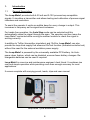
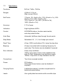
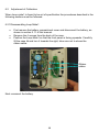
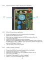
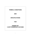
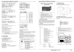
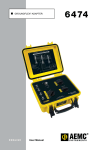
7006 Loop–Mate 1 Loop / Voltage / Current Simulator User Manual Contents Page 1. Introduction 1.1 1.2 1.3 2. 2.2 2.3 2.4 Auto Step Audio Beeping Automatic Power Down 11 11 11 Error Display on the Loop-Mate1 12 Battery Life Battery Replacement 13 13 Maintenance 6.1 6.2 7. 6-7 8 9 10 Power Supply 5.1 5.2 6. 6 Loop Error Indication 4.1 5. Function Select 2.11 Description of typical process loop components Rx Test 4-20mA output TxSim 4-20mA (Current Sink) 0-10vSim Additional Features 3.1 3.2 3.3 4. 2 3-4 5 Loop-Mate1 Operation 2.1 3. General description Specification Front Panel Controls Checking Calibration Adjustment of Calibration 6.21 Disassembling Loop-Mate1 6.22 Trimmer Locations 6.23 Current calibration 6.24 Voltage calibration 6.25 Re-assembly Guarantee & Servicing 14-15 16 16 17 17 17 18 19 All Time Electronics instruments are subject to continuous development and improvement and in consequence may incorporate minor detail changes from the information contained herein. 1 1. Introduction 1.1 General Description The Loop-Mate1 provides both 4-20 mA and 0-10V process loop compatible signals. It simulates a transmitter and allows testing and calibration of process signal indicators and controllers. To assist the operator it emits an audible beep for every change in output. This increases in frequency as the signal level increases. For hands-free operation, the Auto Step mode can be selected and this automatically steps the signal through the span. The operator can then leave the Loop-Mate1 connected while moving to another location to check the signal is arriving correctly. In addition to TxSim (transmitter simulation) and 10vSim, Loop-Mate1 can also provide the loop drive supply that allows an RxTest function (indicator/controller test) without the need for the external excitation power supply. The Loop-Mate1 is powered by the universally available PP3 battery. An Autopower down feature, which can be disabled, ensures fewer battery changes. Rechargeable batteries can be used if required. Loop-Mate1 is a service and maintenance engineer’s best friend. It combines low cost and simple operation while providing more than enough accuracy for most applications. It comes complete with carrying pouch, leads, clips and user manual. Loop-mate 1 plus accessories 2 1.2 Specification Functions: RxTest, TxSim, 10vSim Ranges: 4-20mA, 0-10v dc (Max current 20mA) Set Points: 7 Points: 0% (4mA or 0v), 10% (5.6mA or 1v), 25% (8mA or 2.5v), 50% (12mA or 5v), 75% (16mA or 7.5v), 90% (18.4mA or 9v), 100% (20mA or 10v) Accuracy: 0.1% of span Indication: High brightness LED's Control: UP/DOWN buttons, function select switch, auto-step select button Auto Step: Automatic Up/Down step through the set points Step Rates: Selectable 0.5, 1, 2, 4 or 8 steps per second Dwell Time: At top (100%) and bottom (0%), twice the step time Beeping: A beep is sounded with increasing frequency for each step. This feature can be disabled if required Error Indicator: Faulty loop conditions. TxSim: Loop open circuit or loop resistance too high. RxTest: Inadequate loop excitation supply. 10vSim: Loop short or loop resistance too low. Connections: Two 4mm recessed sockets Power: PP3 battery Auto power down feature (can be disabled if required) Carrying Pouch: Leatherette material. Includes compartment for leads and spare battery. Leads: 4mm gold plated connectors with crocodile clips. 3 Temperature co-efficient: The unit stays in specification over operating temperature range. Operating temp: -5 to 50 degC Storage temp: -30 to 70 degC Operating humid: 10 – 90% non-cond 25degC Dimensions / weight: 14 6.6 2.7cm (6 2.5 1in) / 280gm (10oz) 4 1.3 Front Panel Controls 1) Output Terminals (Recessed) 2) Function Switch 3) Auto Step Button 4) Up/Down Control Buttons 5) Power / Error LED 6) Output LED Indicators 5 2. Loop-Mate1 Operation 2.1 Function Select The Loop-Mate1 has 3 functions: Function 1: Function 2: Function 3: Rx TEST (4-20mA) Tx SIM (4-20mA) 0-10v dc SIM These are selected using the function select switch. Function 2 acts as a current sink only when an external loop excitation supply is connected. 2.11 Description of typical process loop components: 0-10v process loop 4-20mA process loop 4-20mA Process loop and 4-20mA Control loop (Can be used for closed loop control) Tx (transmitter): This component converts physical signals such as pressure, temperature, flow, and level etc, into the loop signals (4-20mA or 0-10v). Rx (receiver): This component measures the loop signal and either displays it (indicator) or converts it to another form e.g. digital output for control purposes, (controller). 6 Process Controllers: This device usually contains both Rx (signal loop) and Tx (control loop) components, which operate in separate loops. The Rx and Tx can be either 4-20mA or 0-10v. Loop excitation supply: A DC power supply (nominally 24v) that drives the loop. 7 2.2 RxTest function 4-20mA The unit can provide current output from 4-20mA with an internally generated loop excitation drive capability. There are seven output set-points over the span. They are indicated on the front panel in both ‘percentage of the span’ and actual mA. An illuminated LED indicates which point is selected. The UP/DOWN buttons can be used to change the set-point. The set-points are: Percentage of Span 0% 10% 25% 50% 75% 90% 100% Current 4mA 5.6mA 8mA 12mA 16mA 18.4mA 20mA Operation: Set the function switch to RxTest. Connect the unit to the process indicator or controller (Rx) observing correct polarity. Turn on the unit by pressing the Down arrow button. Set the required set-point by repeatedly pressing the Arrow keys. The indicator LED will show which set-point is selected. +ve Rx (Indicator) under test -ve Loop-Mate1 (Rx Test function) RxTest Connection Note: The total loop resistance of the Rx indicator plus lead connector should not exceed 600. 8 2.3 TxSim function 4-20mA (Current Sink) Using the TxSim function the unit takes its excitation power from the loop and acts as a current sink. The excitation supply voltage must be in the range 5 to 50 volts dc. Warning: Do not attach the excitation supply to the terminals of the LoopMate1 when TxSim is not selected. The user can set the loop current to one of seven set-points. They are indicated on the front panel in both ‘percentage of span’ and actual mA. The Up/Down buttons can be used to change the set-point. The set-points are: Percentage of Span 0% 10% 25% 50% 75% 90% 100% Current 4mA 5.6mA 8mA 12mA 16mA 18.4mA 20mA Operation: Set the function switch to TxSim. Connect the unit to the loop excitation supply and process indicator or controller (Rx) observing correct polarity. Turn on the unit by pressing the Down arrow button. Set the required set-point by pressing the Arrow keys. The indicator LED will show which set-point is selected. TxSim connection 9 Note: The total loop resistance including connections should not exceed 600. 2.4 10vSim 0-10v function The unit outputs voltage in the range of 0 to 10V. There are seven set-points. The selected set-point is indicated on the front panel in both ‘percentage of span’ and actual volts. The UP/DOWN buttons can be used to change the set-point. The set-points are: Percentage of Span 0% 10% 25% 50% 75% 90% 100% Voltage output 0v 1v 2.5v 5v 7.5v 9v 10v Operation: Set function switch to 10vSim (0-10v). Connect the unit to the process indicator (or controller) observing correct polarity. Turn on the unit by pressing the Down arrow button. Select the required set-point by pressing the Arrow keys. The LED indicator will show which set point is selected. 0 - 10v signal +ve Rx (Indicator) 0 - 10v -ve Loop-Mate1 (10vSim) Voltage loop RxTest connection 10 3. Additional Features 3.1 Auto Step The Loop-Mate1 has the ability to automatically step through the set-points, both up and down. This feature is available for any of the 3 functions (RxTest, TxSim, 10vSim). Auto Step is enabled by pressing the Auto Step button. To disable it press the button again. The length of time the output stays on each level can be altered by pressing the UP or DOWN arrow buttons. The UP shortens the period and the DOWN button increases the period. The different periods are 0.5, 1, 2, 4 or 8 seconds. When the output reaches the 100% or 0% levels, it will dwell (stay) for twice the step period before continuing in the opposite direction. The unit will continue indefinitely in Auto Step mode until the Auto Step button is pressed or the unit is turned off. 100% 2t 0% 0% t Diagram of Auto Step feature (t = step period) In Auto Step mode the indicator LED’s blink at four times the step rate. The stepping direction can be reversed at any time by pressing the Auto Step button twice. Audio beeps (if enabled) occur on each step change. 3.2 Audio (Beeping) The audio beep feature can be toggled on or off by pressing the UP/DOWN arrow keys simultaneously when powering on the unit. This will power up the unit and change the beep setting. Switching on the unit normally will not change the beep setting. 3.3 Automatic power down Auto power down is the default setting. The auto power down feature is incorporated to prevent Loop-Mate1 being inadvertently left switched on after use and draining the battery. The unit will automatically power down if no button is pressed for 15 minutes. Auto power down does not operate when using the auto step mode. The auto power down feature can be disabled when powering up the unit if required. Instead of momentarily pressing the DOWN arrow button, hold it down until the 0% LED comes on (approx 2 seconds). 11 4. Loop Error Indication 4.1 Error display on the Loop-Mate1 Loop Error LED With the RxTest function selected. If the loop is open circuit or resistance too high, the error LED will start flashing. However, short circuit on the loop is not indicated. With the TxSim function selected. If the external loop excitation supply voltage is too low, the polarity is not correct, or the loop open circuit or resistance too high, the error LED will start flashing. However, short circuit on the loop is not indicated. With the 10vSim function selected. If the loop is short circuit, or resistance too low, the error LED and the output LED will both flash. There is also a warning bleep emitted with every flash of the LED’s. This error is caused when Loop-Mate1’s current drive capability (20mA) is exceeded. 12 5. Power supply 5.1 Battery life The unit is powered by a single PP3 battery. Types that can be used are Zinc Carbon (250mAh), Alkaline (450mAh), Lithium (1200mAh) and rechargeable (150mAh). For best performance Lithium batteries are recommended. Under typical usage an Alkaline (450mA) battery will last for approximately 15 - 20 hours of continuous operation. Assuming the Loop-Mate1 is used for approximately 3 hours per day the batteries will last for a week or more. Continuous operation on the RxTest function will shorten the battery life. The unit will automatically power down when the battery voltage is too low. The performance of the unit will remain within specification until power down occurs. Replacement of the battery is then necessary. It is recommended that a spare battery be always carried in the compartment provided in the carrying pouch. 5.11 Battery replacement Slide off the back cover of the case and remove the battery from its compartment. Unclip the battery and replace it with a new PP3 as shown below. Then slide the battery cover back into place. The pictures above show the removal of the battery. The reverse procedure should be used to replace the battery. 13 6. Maintenance 6.1 Checking Calibration Calibration equipment required DMM with accuracy of 0.02% or better. Examples of suitable instruments are Time Electronics’ 5075, or HP 34401A. Calibration should be done at 20C 10 deg C. Checking Calibration (RxTest - Current source) Connect the DMM to the output terminals of the Loop-Mate1. Set the function switch to RxTest. Select the most suitable range on the DMM to measure 20mA dc. Turn on the Loop-Mate1. For each set point, check that the output is within specification (see table below). If a set-point is out of specification then adjustment of the calibration will be required (see later in this section). Allowed error specification. Set-point (mA) 4 5.6 8 12 16 18.4 20 Min value (mA) 3.984 5.584 7.984 11.984 15.984 18.384 19.984 14 Max value (mA) 4.016 5.616 8.016 12.016 16.016 18.016 20.016 Checking Calibration (Voltage) Connect the DMM to the output terminals of the Loop-Mate1. Set the function switch to 0-10v dc. Select the most suitable range on the DMM to measure 10v dc. Turn on the Loop-Mate1. For each set-point check if the reading is within specification. If a set-point is out of specification then adjustment of the calibration is needed (see later in this section). Allowed error specification. Set-point (V) 0 1 2.5 5 7.5 9 10 Min value (V) 0 0.99 2.49 4.99 7.49 8.99 9.99 15 Max value (V) 0 1.01 2.51 5.01 7.51 9.01 10.01 6.2 Adjustment of Calibration When Loop-mate1 is found to be out of specification the procedures described in the following sections must be followed. 6.21 Disassembling Loop-Mate1 First remove the battery compartment cover and disconnect the battery, as shown in section 5.11 of this manual. Remove the 4 screws from the back of the case. Position the Loop-Mate1 so that the front panel is facing upwards. Carefully lift the case lid and turn it towards the right, take care not to stress the ribbon cable. Ribbon cables Next reconnect the battery. 16 6.22 Trimmer Locations (used for adjusting the calibration) P1 6.23 6.24 P2 RxTest (Current source) calibration Connect the DMM to the output terminals of the Loop-Mate1. Set the function switch to Rx Test. Select the most suitable range on the DMM to measure 20mA dc. Turn on the Loop-Mate 1. Press the UP arrow until 20mA output is selected. Adjust P2 until the DMM display reads exactly 20.000mA (if the full scale of the DMM being used is 19.999mA, then use set-point 18.4mA and adjust P2 until the DMM reads 18.400mA. Then re-check all the other set-points. 10vSim (Voltage) calibration Connect the DMM to the output terminals of the Loop-Mate1. Set the function switch to 0 – 10v dc Sim. Select the most suitable range on the DMM to measure 10v dc. Turn on the Loop-Mate1. Press the UP arrow until 10v output is selected. Adjust P1 until the DMM display reads 10.000v. 17 6.25 Re-assembly Disconnect the battery after re-calibration. Refit the lid. Care must be taken to ensure that the ribbon cable linking the two PCB’s is folded in such a way it won’t get trapped when the lid is screwed into place. Replace the lid and screw the four case screws into place. Replace the battery and battery compartment cover. See section 5.11. 18 7. Guarantee & Servicing Guarantee Period The Loop-Mate1 is guaranteed against defects in materials and workmanship for a period of one year from its delivery to the customer. During this period we will, subject to the instrument not being damaged due to maltreatment or overload, repair or replace it free of charge apart from shipping costs. For repair under guarantee, the instrument serial number must always be quoted, together with details of the fault. The purchaser of the instrument must prepay all shipping charges. This guarantee is void if servicing or repair has been attempted by an unauthorized person or agent. Service and Calibration Routine servicing and recalibration of your instrument is an essential part in the life of any calibration instrument. This will ensure that your instrument is performing to its specifications. All repairs are made using high grade and often specialised components to ensure on-going accuracy and performance. Our quality control (ISO9001) ensures the work is undertaken to the highest standards. When an instrument is returned for repair any product enhancements, updates (hardware and software) will be done automatically. Returning Instruments It is preferable to contact Time Electronics or their authorized agent to discuss any special paperwork (customer declarations etc) and shipping requirements. Always include information about the service required and your company details including a contact name, address, phone number and email address. Remember to include the name of the person you spoke to about the return. When returning instruments, please ensure that they have been adequately packed, preferably in the original packing supplied. We will not accept responsibility for units returned damaged. Time Electronics Ltd Unit 11 Botany Industrial Estate Tonbridge, Kent, TN9 1RH 19