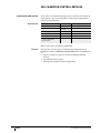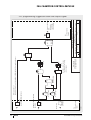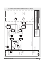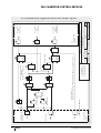
1
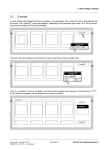
FAG Motion Guard
CHAMPION.CONTROL-IMPULSE
Automatic lubricator
User manual
FAG CHAMPION.CONTROL-IMPULSE
Page
Features
................................................................................................. 3
Application................................................................................ 3
Scope of delivery ....................................................................... 4
Legal requirements.................................................................... 4
Safety guidelines
Responsible persons ................................................................. 4
Qualified personnel ................................................................... 4
Principles .................................................................................. 5
Technical data
Design....................................................................................... 5
Power supply............................................................................. 6
LC unit, masses and dimensions ............................................... 6
Function .................................................................................... 7
Operating conditions ................................................................. 7
Dispensing quantity and
dispensing time
Initial operation
Settings on the drive unit........................................................... 8
Dispensing table ....................................................................... 9
................................................................................................. 10
Initial operation......................................................................... 10
Changing the LC unit
................................................................................................. 11
Changing the dispensing quantity, Reset function ..................... 11
Troubleshooting
................................................................................................. 13
Accessories and service
Accessories ............................................................................... 14
Service ...................................................................................... 14
EU Declaration of Conformity ..................................................... 15
PLC programming suggestions................................................... 17
2
BA 24
Schaeffler Group Industrial
FAG CHAMPION.CONTROL-IMPULSE
Features
Attention!
Application
Attention!
Schaeffler Group Industrial
This user manual describes how to work safely on and with
the automatic lubricator FAG Motion Guard CHAMPION.CONTROLIMPULSE. The safety guidelines must be observed.
Any persons working on and with the lubricator must have the user
manual available for their work and must observe the relevant
information and guidelines.
The user manual must always be complete and in a fully legible
condition.
The relevant disposal guidelines must be observed.
From this point onward, the FAG Motion Guard CHAMPION.
CONTROL-IMPULSE is referred to as the lubricator and the
lubricant cartridge as the LC unit.
The lubricator is clearly identified by a sticker on the drive unit and
the LC unit.
The lubricator is intended for machinery and plant where lubrication
is to be carried out during running and feedback to the machine is
required.
The lubricator supplies the lubrication point with oil or grease at
a pressure up to max. 5 bar constantly, precisely and irrespective
of temperature and can also be switched on and off under machine
control.
Characteristic areas of application include the lubrication points on
rolling and plain bearings, drive and conveyor chains,
guidance systems, open gearboxes and seals.
The lubricator must only be used for the purposes stated in the
order and confirmed by Schaeffler KG and in accordance with
the conditions of use, settings and variations described in this user
manual.
It must be ensured that the correct power supply and connection
to the plant or controller (for example a PLC) are provided.
Connection should only be carried out using the original connection
cable.
Connection should only be made by qualified skilled personnel and
installation must comply with national standards such as IEC or VDE.
The lubrication system must only be equipped with connections and
pressure-resistant feed lines from Schaeffler KG.
The lubricator must be protected against chemically aggressive
ambient media.
BA 24
3
FAG CHAMPION.CONTROL-IMPULSE
Scope of delivery
The lubricator can be used with three LC units of different sizes
to meet individual requirements. The volume of the LC unit and
the lubricator correspond to the specific order.
The delivery should be checked as soon as it is received.
Schaeffler KG accepts no liability for any defects that are the
subject of subsequent complaints.
Any damage in transport must be reported as a complaint to
the deliverer, any missing items or defects must be reported as
a complaint to Schaeffler KG.
Legal requirements
Liability
Attention!
The information, data and guidelines given in the user manual
were current at the time of editorial approval. The data, illustrations
and descriptions cannot be used as grounds for any claims relating
to lubricators that have already been delivered.
Schaeffler KG accepts no liability for any damage or operational
malfunctions that occur as a result of improper use or unauthorised
changes to the drive unit or LC unit.
This also applies to incorrect work on or with the lubricator,
errors in use or adjustment or incorrect variation sizes of
the lubricator or a failure to observe the user manual.
Safety guidelines
Responsible persons
Operator
Attention!
Qualified personnel
4
BA 24
The operator is the natural or juristic person that uses the lubricator
or on whose instruction the lubricator is used.
The operator or his safety co-ordinator are responsible for
compliance with all relevant specifications, guidelines and
regulations.
All work on and with the lubricator may only be carried out by
qualified personnel.
In mounting and maintenance of the lubricator, the relevant
accident preventions specifications and safety specifications must
be observed.
Persons that are authorised by the person responsible for safety
of the plant, on the basis of their experience and knowledge,
to carry out the activities required in the specific case.
Schaeffler Group Industrial
Attention!
Technical data
Design
The lubricator must be filled with the correct oil or grease and
adjusted such that, when it is correctly adjusted and mounted
and used as specified, it functions without defects and does not
cause any hazards. This also applies to the interaction with
the complete plant and the points to be lubricated.
Material damage that could arise due to failure of the lubricator
must be prevented by suitable measures.
All retrofitting, modification and conversion of the lubricator is
prohibited.
While working on machinery and plant, the safety guidelines and
user manuals of the manufacturers must be observed.
The LC unit must not be opened or refilled under any circumstances.
The safety data sheets for the oils and greases must be observed.
Only original LC units from Schaeffler KG may be used.
The lubricator corresponds to the state of technology at the time
of delivery and is always regarded as operationally reliable.
It comprises, as shown in Figure 1:
■ closing stopper �
■ LC unit � containing lubricant, screw thread R1/4
(to be ordered separately)
■ drive system �, comprising a geared motor and an electronic
unit (state serial number on any queries)
■ LED function display �
■ cover �
■ cable with plug � (to be ordered separately).
With the exception of the LC unit, all the components can be reused
several times.
4
3
� Closing stopper
� LC unit
� Drive system
� LED function display
� Cover
� Cable with plug
6
5
1
2
141 237
Principles
Figure 1
Components of the FAG lubricator
Schaeffler Group Industrial
BA 24
5
FAG CHAMPION.CONTROL-IMPULSE
Power supply
Key data
Compilation of data:
Description
Technical data
Power supply
15 V DC to 25 V DC
(max. 30 V DC, 5% residual ripple)
Current consumption
typically 0,2 A
(max. starting current 1,2 A)
79,9 ⍀/km at +20 °C
Conductor resistance
Permissible
temperature
Stationary
condition
–25 °C to +70 °C
Moving condition
Cable design
Attention!
LC unit, masses
and dimensions
–5 °C to +70 °C
Description
Technical data
Cross-section area of conductor
4⫻0,25 mm2
Cord design, diameter
Cu cord 32⫻0,1 mm ⭋, blk
Insulation
PVC, 1,3 ⫹ 0,05 mm ⭋
Wall thickness approx. 0,32 mm
Material: cable outer sheath
PUR/black
Outputs
each max. 400 mA,
short circuit-proof
The cable is suitable for use in chain link trunking, the minimum
bending radius is 60 mm.
The power supply must be active for at least two minutes in order
to ensure the correct running time.
The maximum load on the outputs (Pin 2 and Pin 4) must not exceed
400 mA in each case.
The drive unit and LC unit together form the lubricator.
Type
Volume
Diameter
Total length Mass
D
L
Empty
Filled with
MULTITOP
cm3
mm
mm
kg
kg
LC60
60
71
142
0,310
approx. 0,360
LC120
120
71
165
0,320
approx. 0,430
LC250
250
71
215
0,360
approx. 0,590
2
Figure 2
Lubricator
6
BA 24
1
3
141 238
� Diameter
� Length
� Screw thread R1/4
Schaeffler Group Industrial
Function
When voltage (as a impulse) is applied to the lubricator,
it releases a single, adjustable dispensing quantity.
The lubricant is moved out of the LC unit by a driven spindle
in the plunger. The plunger builds up a pressure of up to 5 bar in
the LC unit; above this value, the automatic pressure limiter
switches off the system after starting up several times.
The size of the LC unit and the dispensing quantity per impulse
are set on the quadruplex encoder.
Operating conditions
Ambient temperature
Ambient conditions
Storage
Schaeffler Group Industrial
A uniform dispensing behaviour and pressure build-up to a
maximum of 5 bar can only be ensured in the temperature range
from –10 °C to +50 °C.
If the individual components are fitted together correctly,
the lubricators are resistant to dust and spray water.
However, the sealing rings and plastics may be attacked by
ambient media.
Lubricators must only be stored in interior rooms that are dry,
dust-free and protected against sunlight, at a storage temperature
of +15 °C to +25 °C.
The LC unit can be stored for up to two years; the lubricant fill date
should be taken as the controlling factor. All other components
should be replaced after a maximum of two years.
BA 24
7
FAG CHAMPION.CONTROL-IMPULSE
Dispensing quantity
and dispensing time
Settings on the drive unit
Incorrect settings will lead to overlubrication or underlubrication
with the possibility of secondary damage.
Unscrew the cover of the drive unit. The quadruplex encoder is
located on the control circuit board, Figure 3.
The two switches � with the designation “TIME” are used to
set the dispensing quantity. The position of the switch � with
the designation “VOL” depends on the size of the LC unit.
The switches can be adjusted with the aid of a small screwdriver.
Screw the cover back onto the drive unit.
1
� Red LED
� Green LED
� Jack
� Circuit board
� Quadruplex encoder
� TIME (time adjustment)
� VOL (volume of LC unit)
3
2
Figure 3
Control circuit board of drive unit
LED signals
8
BA 24
4
6
5
7
141 239
Attention!
The LEDs on the control circuit board, Figure 3, � and �
are interpreted as follows:
LED lit
Signal
Description
Green
Green continuous signal
System running
Red
Red continuous signal ⭐30 s
Motor running:
dispensing operation
Red
Red continuous signal ⭓30 s
Error or malfunction
Red and green
Red and green
continuous signal
Replace LC unit immediately
Schaeffler Group Industrial
Dispensing table
Settings
on quadruplex encoder
Attention!
Schaeffler Group Industrial
Possible positions of quadruplex encoder
Quadruplex encoder
Switch 1 and switch 2
“TIME”
Switches 3 and 4 “VOL”
Dispensing quantity in cm3 per impulse,
1 cm3 艐 0,9 g lubricant
LC60
LC120
LC250
2,11
2,11
2,11
1,06
1,06
1,06
0,53
0,53
0,53
0,26
0,26
0,26
As soon as the voltage is applied (15 V DC to 25 V DC,
max. 30 V DC), the lubricator releases the set lubricant quantity
once only.
The voltage must be applied for at least as long such that
the dispensing operation is completed after a maximum of
two minutes.
Before each additional dispensing operation, the voltage must be
disconnected for at least 15 seconds and then switched on again.
BA 24
9
FAG CHAMPION.CONTROL-IMPULSE
Initial operation
The FAG Motion Guard CHAMPION.CONTROL-IMPULSE is delivered
as standard without an LC unit and with a preset dispensing
quantity of 0,53 cm3.
Before the lubricator is installed, the lubrication points and
the lubricant feed lines must be sufficiently prelubricated using
the same lubricant as is contained in the lubricator.
Appropriate 400 g lubricant cartridges or oil containers are
available as accessories.
■ Support adapters (accessories) should be used for mounting.
■ If the lubricator is mounted vertically, it should be secured using
a retaining clip (accessory).
2
Figure 4
Pin assignment
3
1
4
141 220
� Brown cable = power supply (plus)
� White cable = Green digital LED (output)
� Blue cable = power supply (minus)
� Black cable = Red digital LED (output)
Initial operation
Attention!
10
BA 24
Mount the lubricator using a support adapter or retaining clip.
Always check the settings of the lubricator before initial operation
and make corrections as necessary.
Make connections precisely in accordance with the user manual.
An incorrect connection can lead to destruction of the electronics.
Mount the lubricator filled with oil vertically, with the outlet facing
down. Fit the oil valve. Provide additional sealing of the connectors
using a suitable sealing material.
Work steps:
■ Check the lubricator for external damage.
■ Prelubricate the lubrication point and the feed lines.
■ The thread of the LC unit must match the thread of the screw
mounting point (R1/4).
■ Connect the power cable in accordance with the PLC circuit
diagrams to the status display in the switch cabinet.
■ Check the settings on the encoder.
Schaeffler Group Industrial
■ Remove the closing stopper from the LC unit and screw
the completed lubricator finger tight into the lubrication point.
Do not screw in a second time since this can impair the
self-sealing effect of the thread.
■ Connect to the power grid.
■ After Reset, operation will start with the set pause time.
During operation
Check seal integrity and the lubricant fill level as well as the correct
position and finger tight screw mounting of all components
regularly.
Changing the LC unit
Attention!
Changing the dispensing
quantity
Reset function
Schaeffler Group Industrial
The LC unit must not be opened or refilled under any circumstances.
Only new, completely filled FAG LC units should be used.
Protect the drive system and control circuit board against moisture.
The unit should only be changed in dry conditions.
Dispose of old parts in accordance with the applicable regulations.
Once the red and green LEDs light at the same time,
the empty LC unit must be replaced immediately.
Work steps:
■ Disconnect from the power grid.
■ Unscrew the lubricator completely from the lubrication point.
■ Unscrew the cover of the drive system.
■ Remove the drive system from the LC unit.
■ If necessary, set the new size of the LC unit and dispensing
quantity, page 9.
■ Position the drive system on the new LC unit,
ensuring that the teeth engage with each other.
■ Screw mount the cover of the drive system finger tight
to the LC unit.
Continue the steps in accordance with “Initial operation”, page 10.
The Reset function switches the lubricator to its base condition by
restoring the stored parameters.
The process:
■ Disconnect from the power grid.
■ Unscrew the lubricator completely from the lubrication point.
■ Unscrew the LC unit from the drive unit.
■ Set the two switches “VOL” of the quadruplex encoder to
the position “Reset”, Figure 5 �, page 12.
BA 24
11
FAG CHAMPION.CONTROL-IMPULSE
Attention!
After these steps:
■ Reconnect to the power grid.
■ Once the motor has run for approximately 2 seconds,
LED � and LED �, Figure 3, page 8 will light.
■ Disconnect from the power grid.
■ Make the new settings, see page 8.
■ During setting, keep the Reset pin pressed, Figure 5 �.
■ Reconnect to the power grid.
■ After three seconds, release the Reset pin and disconnect from
the power grid.
■ Screw together the lubricator.
During this operation, the requirement for replacement
of the LC unit according to the fill level of the LC unit
(continuous signal of the red and green LEDs)
may be inappropriate.
Ensure that the condition is correct and monitor the end of
the lubrication period on site.
1
Figure 5
Reset for initial operation and for
subsequent modifications
12
BA 24
2
141 240
� Reset pin on the drive unit (changes)
� Reset position of switch “VOL”
(initial operation)
Schaeffler Group Industrial
Troubleshooting
Malfunctions of the lubricator should be analysed and rectified
using the table. Please contact Schaeffler Customer Service if a
defect occurs that is not listed in the table.
Defect
Possible cause
Remedy
Lubricator not
functioning
Cable connected
incorrectly
■ Check connection
assignment
Cable breakage
■ Check power,
connect new cable
No power
■ Power supply too low for
the number of lubricators
connected
Machine relay defective
■ Replace relay
Setting of “VOL” switch
does not correspond to
volume of LC unit
■ Fit full LC unit
Green LED indicating
“System running”
although LC unit is
empty
Partially filled LC unit
was replaced by almost
empty LC unit
■ Clean feed line
and connectors,
then switch off and on,
Counterpressure too high
see page 11
Red LED indicating
Feed line and connectors
“Defect, malfunction” are blocked
Lubricator dispensing Switch “TIME” set
too quickly
incorrectly
■ Correct switch settings,
see page 9
Lubricator indicating
“LC unit empty”
(red and green LEDs)
although lubricant is
still present in the
LC unit
■ Fit full LC unit
Setting of “VOL” switch
does not correspond to
LC unit
Almost empty LC unit
was replaced by partially
filled LC unit
Reset pin was not pressed ■ Move drive unit by a few
during assembly
teeth so that the Reset
pin can be pressed
Incorrect dispensing
quantity
Schaeffler Group Industrial
Encoder set incorrectly
■ Make corrections,
see page 8
BA 24
13
FAG CHAMPION.CONTROL-IMPULSE
Accessories and service
Accessories
Accessories and replacement parts must conform to the technical
requirements. This is ensured when using original replacement
parts from Schaeffler KG.
Description
Technical data Ordering designation
Cable with jack plug
5m
ARCALUB-CONTROL.CABLE-5M
Support bracket
Thread G1/4,
external
ARCALUB.ADAPTER
Retaining clip
–
ARCALUB.CLIP
Holder with insert
–
ARCALUB.HOLDER-KIT
Oil valve
–
ARCALUB.OILVALV-G1/4
400 gram grease cartridge
or oil in container for
prelubrication
–
Available by agreement
Other accessories available by agreement.
Service
14
BA 24
The operator has the option of returning the empty lubricator
FAG Motion Guard CHAMPION.CONTROL-IMPULSE to Schaeffler KG
for:
■ disposal of the used parts in an environmentally-friendly
manner,
■ replacement of the LC unit,
■ setting of the required dispensing quantity.
Schaeffler Group Industrial
00014100
EU Declaration of Conformity
Schaeffler Group Industrial
BA 24
15
16
BA 24
0013BD3
PLC
connection strip
Inputs
1
in
I1
Green LED
White cable
2
in
I2
Red LED
1
No green signal
inv
1
No red signal
inv
CHAMPION CONTROL IMPULSE
Black cable
3
in
l3
Power supply
CHAMPION CONTROL IMPULSE
Cable breakage
and
&
on delay
50 sec
on delay
120 sec
Schaeffler KG
Georg-Schäfer-Str. 21
97421 Schweinfurt
B01, B09 + B11 optional,
only necessary for storage
of error display
and
&
or
1
When using B02, I3
Malfunction display only if CHAMPION CONTROL IMPULSE is supplied with power
Q
latching relay
Reset
Set
1
GRÖSSE
MASSTAB
28.a
BLATT
ZEICHN.NR.
At/Za
Erstellt
08.01.2001
1 von 1
1.1
REV.
Connect out Q2 = high
with
- malfunction
- LC unit empty
- cable breakage
PLC
connection strip
Outputs
out
Logic scheme for evaluation of LED signals on FAG Motion Guard
CHAMPION CONTROL IMPULSE from version 3.1
Separate display of
normal function - malfunction/cable breakage - empty level of LC unit
and
&
FAG CHAMPION.CONTROL-IMPULSE
PLC programming suggestion with one output signal
Schaeffler Group Industrial
Schaeffler Group Industrial
1
BA 24
00013BDE
PLC connection strip
Inputs
Cable breakage
and
&
and
&
or
1
50 sec
on delay
120 sec
on delay
1
or
1
or
Connect out B04 directly
with input B13 if
B11/B12 is not being used
Schaeffler KG
Georg-Schäfer-Str. 21
97421 Schweinfurt
Q
Q
latching relay
Reset
Set
B11, B12 optional
latching relay
Reset
Set
and
&
PLC
connection strip
Outputs
out
1
out
1
Q2 = active
with
- malfunction
- cable breakage
Q1 = active
with
- LC unit empty
MASSTAB
GRÖSSE
BLATT
28.c
At/Za
ZEICHN.NR.
Erstellt
08.01.2001
1 von 1
Separate display of
normal function - malfunction/cable breakage - empty level of LC unit
Logic scheme for evaluation of LED signals on FAG Motion Guard
CHAMPION CONTROL IMPULSE from version 3.1
When using B13, I3
Malfunction display only if CHAMPION CONTROL IMPULSE is supplied with power
No green signal
inv
1
No red signal
inv
1
50 sec
in
l3
Power supply
CHAMPION CONTROL IMPULSE
3
in
I1
Green LED
White cable
in
I2
Red LED
2
CHAMPION CONTROL IMPULSE
Black cable
on delay
REV.
1.1
PLC programming suggestion with two output signals
17
18
BA 24
1
00013BE0
PLC connection strip
Inputs
Cable breakage
and
&
and
&
or
1
50 sec
on delay
120 sec
on delay
or
1
or
1
Connect out B04 directly with
input B13 if
B11/B12 is not being used
Schaeffler KG
Georg-Schäfer-Str. 21
97421 Schweinfurt
Q
Q
latching relay
Reset
Set
B11, B12 optional
latching relay
Reset
Set
and
&
1
PLC
connection strip
Outputs
out
1
out
1
out
Q3 = active
with
- malfunction
- cable breakage
Q2 = active
with
- LC unit empty
Q1 = active
with
- normal function
MASSTAB
GRÖSSE
28.b
BLATT
ZEICHN.NR.
At/Za
Erstellt
08.01.2001
1 von 1
Separate display of
normal function - malfunction/cable breakage - empty level of LC unit
Logic scheme for evaluation of LED signals on FAG Motion Guard
CHAMPION CONTROL IMPULSE from version 3.1
When using B13, I3
Malfunction display only if CHAMPION CONTROL IMPULSE is supplied with power
No green signal
inv
1
No red signal
inv
1
50 sec
3
in
l3
Power supply
CHAMPION CONTROL IMPULSE
in
I1
Green LED
White cable
2
in
I2
Red LED
CHAMPION CONTROL IMPULSE
Black cable
on delay
REV.
1.1
FAG CHAMPION.CONTROL-IMPULSE
PLC programming suggestion with three output signals
Schaeffler Group Industrial
Notes
Schaeffler Group Industrial
BA 24
19
MATNR 032821395-0000 / BA 24 / GB-D / 200902 / pdf only
Schaeffler KG
Every care has been taken to ensure the
Postfach 1260
correctness of the information contained
97419 Schweinfurt (Germany)
in this publication but no liability can be
Georg-Schäfer-Straße 30
97421 Schweinfurt (Germany)
Service Hotline:
accepted for any errors or omissions.
We reserve the right to make technical
changes.
Phone
+49 2407 9149-99
© Schaeffler KG · 2009, February
Fax
+49 2407 9149-59
This publication or parts thereof may not
E-mail
support@fis-services.de
be reproduced without our permission.
Internet www.fis-services.de
BA 24 GB-D