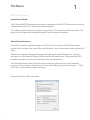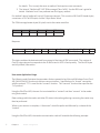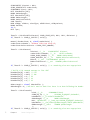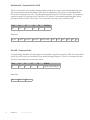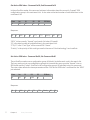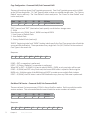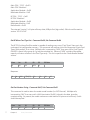
1
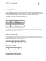
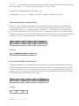
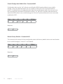
USB CCID
Installation
User Manual
99009180 Rev C
Thank You!
Congratulations on the purchase of your USB CCID device(s). RF IDeas hopes you enjoy using
the readers as much as we enjoyed creating and developing them. Configuration is easy, so you
will be able to quickly take advantage of a more secure environment in your business, school, or
organization.
Please call our Sales department if you have any questions or are interested in our OEM and
Independent Developer’s programs.
We look forward to your comments and suggestions for our product line! Please go to
www.RFIDeas.com and follow the Support a Learning Center link for more details about our
product line.
We are always discovering new applications for our product line(s). There are several software
developer’s licensing our technology so the solution you are looking for may already be developed.
Thank you,
The RF IDeas Staff
Need Assistance?
2
Ph: 847.870.1723
Fx: 847.483.1129
E: Sales@RFIDeas.com
TechSupport@RFIDeas.com
Contents
2
Thank You!
4
4
Chapter 1: The Basics
USB CCID Overview
5
Chapter 2: Reader Configuration
5Configuration
6
Utility Messages
11
Chapter 3: Utility Commands
11Commands
3
20
Chapter 4: Support
20Precautions
20
Before You Call Technical Support
20
Talking To The Technician
23
Index
24
Other Products and Accessories
The Basics
1
USB CCID Overview
Introduction to Reader
The RF IDeas USB CCID contactless card reader is designed to the USB CCID class specifications and
supplemented by the PC/SC Working Group specifications.
This reader provides a Smart Card interface using protocol T=0 to retrieve card ID information. The
reader is also configured and updated through this same interface and protocol.
Device Connection Access
Access to the reader is supplied through various PC OS drivers (not part of the RF IDeas reader
product) which, at least in the case of Microsoft Windows 7 and 8, are bundled with the standard OS
install.
There are no installation files supplied or required under the Microsoft Windows OS. Just plug
the reader into a Full Speed (12 Mbps) USB port and the OS does the rest. If the reader does NOT
enumerate, updates to one or more of the driver files may be necessary.
The Microsoft Windows Smart Card API uses the underlying OS drivers that can be viewed by
opening the “Driver Details” window from the “Properties” dialog of “Devices and Printers” / “CCID
Card Proxy” device when the reader is attached.
Microsoft Windows 7 OS driver details:
4
Reader Configuration
2
Configuration
Reader USB Strings and Class Descriptor Details
USB VID: 0x0C27, USB PID: 0xCCDA
Manufacturer String: “RFIDeas”
Product String: “CCID Card Proxy”
The required bulk endpoints IN / OUT are implemented.
Only Protocol T=0 using short APDUs is implemented.
Class Descriptor:
0x36 ; length
0x21 ; Descriptor Type == “CCID Class Functional Descriptor type”
0x10, 0x01 ; CCID BCD Release version 1.10
0x00 ; Max Card Slot index (00-0F)
0x01 ; Voltage support, bitwise OR: 1=5.0V, 2=3.0V, 4=1.8V
0x01, 0, 0, 0 ; dwProtocols: bitwise OR, 1==T0, 2==T1
LILENDIAND2BYTE ( 3580 ) ; dwDefault ICC Clock Frequency in KHz
LILENDIAND2BYTE ( 3580 ) ; dwMaximum ICC Clock Frequency in KHz
1 ; bNumClockSupported (0 means use Default & Max above, Microsoft maybe wants “1”)
LILENDIAND2BYTE ( 9600 ) ; dwDataRate bps (ICC I/O)
LILENDIAND2BYTE ( 9600 ) ; dwMaxDataRate (ICC I/O)
1 ; bNumDataRatesSupported
LILENDIAND2BYTE ( 0 ) ; dwMaxIFSD Max IFSD supported by CCID for protocol T=1
LILENDIAND2BYTE ( 0 ) ; dwSynchProtocols
LILENDIAND2BYTE ( 0 ) ; dwMechanical (Contactless)
0x7E, 0x00, 0x02, 0x00 ; dwFeatures
LILENDIAND2BYTE ( 64 ) ; dwMaxCCIDMessageLength (wMaxPacketSize of the Bulk-OUT
endpoint)
0xFF ; bClassGetResponse
0xFF ; bClassEnvelope
LILENDIAND2BYTE ( 0 ) ; wLCDLayout (0000 = NO LCD)
0x00 ; bPINSupport
0x01 ; bMaxCCIDBusySlots
5
Utility Messages
USB Control Endpoint Messages
Get Clock Frequencies [Return the single defined value of USB Class Descriptor]
Get Data Rates [Return the single defined value of USB Class Descriptor]
Abort
USB Interrupt Endpoint IN Messages
Card Inserted (not supported)
Card Removed (not supported)
This optional ENDPOINT is NOT supported! Its use makes it IMPOSSIBLE to configure and bootload
the reader unless a card is “tapped” to prime the message pump. Instead, the reader always reports
a “Slot Status” of “Powered” and “Active” and the Windows OS API call, “ScardGetStatusChange(…)”
will ALWAYS report the same so it cannot be used to indicate that a user has “tapped” a card on the
reader. The reader must be polled directly for the presence of a card instead of polling the OS driver
stack for the presence of a card.
USB Bulk Endpoint OUT / IN Messages
6
Bulk Out Message
PC_to_RDR_IccPowerOn
Bulk IN Response
RDR_to_PC_DataBlock
Status
0
Error
0
Support
Yes
PC_to_RDR_IccPowerOff
RDR_to_PC_SlotStatus
0
0
Yes
PC_to_RDR_GetSlotStatus
RDR_to_PC_SlotStatus
0
0
Yes
PC_to_RDR_XfrBlock
RDR_to_PC_DataBlock
0
0
Yes
PC_to_RDR_GetParameters
RDR_to_PC_Parameters
0
0
Yes
PC_to_RDR_ResetParameters
RDR_to_PC_Parameters
0x40
0
NO
PC_to_RDR_SetParameters
RDR_to_PC_Parameters
0x40
0
NO
PC_to_RDR_Escape
RDR_to_PC_Escape
0x40
0
NO
PC_to_RDR_IccClock
RDR_to_PC_SlotStatus
0x40
0
NO
PC_to_RDR_T0APDU
RDR_to_PC_SlotStatus
0x40
0
NO
PC_to_RDR_Secure
RDR_to_PC_DataBlock
0x40
0
NO
PC_to_RDR_Mechanical
RDR_to_PC_SlotStatus
0x40
0
NO
PC_to_RDR_Abort
RDR_to_PC_SlotStatus
0
0
Yes
PC_to_RDR_SetRateAndClock
RDR_to_PC_RateAndClock
0x40
0
NO
Chapter 2
Reader Configuration
Messages that are NOT supported will return a Status Word of “6A81” (command not supported).
Notes on ISO/IEC 7816 Message Construction
Please refer to:
ISO/IEC 7816-3 “Cards with contacts - Electrical interface and transmission protocols”
Section 10 “Protocol T=0, half-duplex transmission of characters”
Section 10.3.2 “Command header”
Section 12.2 Command-response pair transmission by T=0
PC/SC Workgroup – “Interoperability Specification for ICCs and Personal Computer Systems” parts 1
through 10.
The general form of a message is:
Class
Ins
P1
P2
P3
P3 Data
In the context of this document, the “Class” byte differentiates between a CCID/PCSC message
(Class = 0xFF in our case) and an RF IDeas internal command (Class = 0xFA). The “Ins” byte
specifies a specific command or command family. Parameters “P1” and “P2” are used by the
command. The “P3” byte specifies the number of data bytes (“P3 Data”) that follow the header in
the transmission.
In the case where there is no data to send along with the header, only 4 bytes should be sent.
Class
Ins
P1
P2
In the “short APDU” used by the RF IDeas reader, a “P3” byte of zero implies that 256 bytes follow as
“P3 Data”. The RF IDeas CCID reader has a Bulk Endpoint IN/OUT capacity of 64 bytes. The host to
reader data consists of a 10-byte CCID header and a 5-byte 7816 header (when “P3 Data” follows).
Therefore, the maximum P3 value is practically limited to 49 bytes (64 - 10 - 5). The inbound (reader
to host) response consists of the 10-byte CCID header and the 7816 response data. Therefore, the
response data is practically limited to 54 bytes (64 - 10).
Methods of Returning the Card ID
There are currently three methods of retrieving the “Card ID” from the reader.
1. The ISO 7816 message (Class 0xFF) as “PC_to_RDR_XfrBlock” data, Get UID, returns the
Card ID Header and the Card ID in the “RDR_to_PC_DataBlock” response.
2. The internal “GetQueuedID” ISO 7816 message(s) (Class 0xFA). See the SDK user’s guide
7
Chapter 2
Reader Configuration
for details. This is nearly the same as method 1 but requires more commands.
3. The internal “GetActiveID” ISO 7816 message (Class 0xFA). See the SDK user’s guide for
details. Methods 1 and 2 are preferred over this legacy method.
For method 1 above (preferred), up to 42 bytes are returned. This consists of 8 Card ID Header bytes,
a maximum of 32 Card ID bytes, and the 2-byte Status Word.
The 7816 message header bytes (4 bytes) sent to the reader would be:
Class
Ins
P1
P2
P3
FF
CA
00
00
xx
P3 Data
Response:
Byte 0,1
Byte 2,3
CardTypeL/H IDAgeL/H
Byte 4
IDOvrn
Byte 5 Byte 6
Byte 7
Bytes 8 to (N+8) SW1
[RFU] ID BitCnt ID ByteCnt (N) Card ID[N]
90
SW2
00
This data combines the data returned from several of the internal SDK commands. The number of
Card ID bytes returned corresponds to the ID BitCnt and is NOT a fixed quantity. The Card ID bytes
are left justified, little endian.
User-mode Application Usage
The following code illustrates the parameters that are passed to key Microsoft Windows Smart Card
API (WinSCard API) functions to achieve communications. Specification of a “shared” connection
with the protocol “T0” is used for the “connect” function. The “transmit” function then specifies the
T=0 protocol.
Using the WinSCard API, the user first must establish a “context” and then “connect” to the reader
using that context.
Data exchange with the reader and other OS status information gathering concerning the reader may
then be performed.
When a user session is complete, a “disconnect” should be performed followed by a release of the
“context”.
Using the WinSCard API, the reader communication code will resemble the following example:
8
Chapter 2 Reader Configuration
SCARDCONTEXT hContext = NULL;
SCARD_READERSTATE readerState;
SCARDHANDLEhCard = NULL;
BYTE bSendBuffer[256];
DWORD dwSendLength;
BYTE bRecvBuffer[256];
DWORD dwRecvLength;
DWORD dwActiveProtocol;
LONG lResult;
WORD wIDAge, wIDOvrn, wCardType, wIDBitCount, wIDByteCount;
DWORD dwState;
int i;
BYTE *puc;
lResult = SCardEstablishContext( SCARD_SCOPE_USER, NULL, NULL, &hContext );
if( lResult != SCARD_S_SUCCESS ) exit(1);
memset( &readerState, 0, sizeof(readerState) );
readerState.szReader = “RFIDeas CCID Card Proxy 0”;
readerState.dwCurrentState = SCARD_STATE_UNAWARE;
lResult = SCardConnect(
hContext, //__in
SCARDCONTEXT hContext,
readerState.szReader, //__in
LPCSTR szReader,
SCARD_SHARE_SHARED, //__in
DWORD dwShareMode,
SCARD_PROTOCOL_T0, //__in
DWORD dwPreferredProtocols,
&hCard, //__out
LPSCARDHANDLE phCard,
&dwActiveProtocol //__out
LPDWORD pdwActiveProtocol
);
if( lResult != SCARD_S_SUCCESS ) exit(1); // or something else more appropriate
// Build a T=0
bSendBuffer[0]
bSendBuffer[1]
bSendBuffer[2]
bSendBuffer[3]
bSendBuffer[4]
command
= 0xFF;
= 0xCA;
= 0; //
= 0; //
= 0; //
message to “Get UID”
// CLA
// INS
P1
P2
P3
dwRecvLength = sizeof( bRecvBuffer );
dwSendLength = 4; // We don’t need to send P3 as there is no data following the Header.
lResult = SCardTransmit(
hCard, //__in
SCARDHANDLE hCard,
SCARD_PCI_T0, //__in
LPCSCARD_IO_REQUEST pioSendPci,
bSendBuffer, //__in LPCBYTE bSendBuffer,
dwSendLength, //__in
DWORD cbSendLength,
NULL, //&ioRecvPci, //__inout_opt LPSCARD_IO_REQUEST pioRecvPci,
bRecvBuffer, //__out_bcount(*pcbRecvLength) LPBYTE pbRecvBuffer,
&dwRecvLength //__inout
LPDWORD pcbRecvLength
);
if( lResult != SCARD_S_SUCCESS ) exit(1); // or something else more appropriate
9
Chapter 2
Reader Configuration
wCardType = ((WORD)bRecvBuffer[1] << 8) + (WORD)bRecvBuffer[0];
wIDAge = ((WORD)bRecvBuffer[3] << 8) + (WORD)bRecvBuffer[2];
wIDOvrn = (WORD)bRecvBuffer[4];
wIDBitCount = (WORD)bRecvBuffer[6];
wIDByteCount = (WORD)bRecvBuffer[7];
printf( “CardType: %04X, IDAge: %u, IDOvrn: %u, IDBits: %u, IDBytes: %u\n”,
wCardType, wIDAge, wIDOvrn, wIDBitCount, wIDByteCount );
printf( “Card ID:” );
puc = &bRecvBuffer[8];
for(i = 0; i < wIDByteCount; i++) printf(“ %02X”, (WORD)*(puc++) );
printf(“\n”);
SCardDisconnect(
hCard, //__in
SCARDHANDLE hCard,
SCARD_LEAVE_CARD //__in
DWORD dwDisposition
);
hCard = NULL;
SCardReleaseContext( hContext );
hContext = NULL;
exit(0);
10 Chapter 2 Reader Configuration
3
Utility Commands
Commands
Internal ISO-7816 Messages
This section details the “internal” commands (instructions, INS) that may be used to configure the
reader’s operational parameters and query the reader for information. The messages are constructed
as in the example above except the “Class” byte is 0xFA for all of the internal commands.
The returned “Status Word” may be one of the following:
SW1
90
6D
6B
67
6A
SW2
00
00
00
00
82
Definition
Success
Invalid Instruction
P1, P2 Incorrect
P3 Incorrect
Card Not Found
Also note that in the case where no data is returned, some of the commands will echo the INS byte
before the Status Word while others will not.
Get Active ID - Command 0x00
This command retrieves information on the card that is currently on the reader. This data expires
within about one second after the card has left the field so the preferred method would involve using
the queued ID facilities which are not so time critical.
Class
FA
Ins
00
P1
LEN
P2
xx
P3
xx
Response if a card is present:
00
IDdata[LEN]
90
00
Response if NO card is present:
00
11
00 x LEN
6A
82
P3 Data
The “LEN” is the requested return data length of the “IDdata” which includes a 4-byte header so LEN
should always be >= 4. To retrieve 32 bytes of a card ID, set LEN to 36.
IDdata[LEN] = IDdataHeader[4], IDData[LEN - 4].
IDdataHeader[4] = [LEN – 4], IDBitCnt, RFU, RFU = IDByteCnt, IDBitCnt, RFU, RFU.
Get Configuration Block - Command 0x01
Each Card Type in the reader’s card search list has five 8-byte blocks of data associated with the
processing of that particular Card Type. The Card Type configuration data for any one Card Type
is accessed by “framing” the data group into an “SDK” buffer. The selection of the Card Type data
group is accomplished using “Set Active SDK Index” command described later. Once the Card Type
data group has been copied into the SDK buffer, the individual 8-byte Blocks can be fetched using this
command. The “BLK” parameter specifies which 8-byte block (0 through 4) will be fetched.
Class
FA
Ins
01
P1
BLK
P2
xx
P3
xx
P3 Data
Response:
01
CfgData[8]
90
00
Set Configuration Block - Command 0x81
Once the configuration block has been fetched by the user, it may be modified and written back to
the SDK buffer RAM using this command. The data is not written to non-volatile memory until the
“Commit” command is issued. It is possible for the user to write a configuration block without first
reading it but it is usually wise to fill known locations with well understood data while ensuring that
unknown locations are left in the original state.
Class
FA
Ins
81
P1
BLK
90
00
P2
xx
Response:
81
12
Chapter 3 Utility Commands
P3
08
P3 Data
CfgData[8]
Commit Configuration RAM to Flash - Command 0x02
Configuration data may be “set” without committing the RAM-based variables to non-volatile
storage. If the user needs the data to survive a power or reset cycle, this command should be
issued. If multiple blocks of configuration data need to be written to the reader, the user may issue
this command just once after all of the data is written. If a “Set LUID” has been used and the user
wants the LUID written to non-volatile storage, the “bSvLuid” byte should be set to a non-zero value
(preferrably 0xFF).
Class
FA
Ins
02
P1
bSvLuid
P2
xx
P3
xx
P3 Data
Response:
90
00
Restore Factory Defaults - Command 0x03
This command will restore all of the configuration data to the factory default values and save the data
to non-volatile storage (a “commit” is not needed).
Class
FA
Ins
03
P1
xx
P2
xx
Response:
90
13
Chapter 3 00
Utility Commands
P3
xx
P3 Data
Get Device ID - Command 0x04 / 0x05
These 2 commands return exactly the same data except for the command acknowledgement byte.
The returned data contain the reader LUID, the main application FW version, and the bootloader
FW version within the main FW. This data references the Control CPU of the reader. The preferred
method to get all FW versions is the “Get Micro FW Version” command(s) described later which
provides access to the RF CPU as well. This command is the only way to read the LUID.
Class
FA
Ins
04
P1
xx
P2
xx
P3
xx
P3 Data
Response:
04/05
wLUIDL wLUIDH
VMin|V0
VMajH|VMajL BLV3 BLV2
BLV1
BLV0
90 00
Set LUID - Command 0x06
A logical reader identifier may be assigned to the reader using this command. After this command is
issued, the LUID may be committed to non-volatile storage using the “Commit” command with the
“bSvLuid” parameter set to a non-zero value.
Class
FA
Ins
06
P1
xx
P2
xx
Response:
06
14
Chapter 3 90
00
Utility Commands
P3
02
P3 Data
Luid[2] (little endian)
Get Active SDK Index - Command 0x09, Sub Command 0x01
In the pcProxPlus reader, this command retrieves information about the currently “framed” SDK
configuration group in the card search list. It also returns the total number of card definitions in the
card search list.
Class
FA
Ins
09
P1
01
P2
xx
P3
xx
P3 Data
Response:
09
01
NDX
N
00
CTL
CTH
Priority
90
00
“NDX” is the currently “framed” card search list index (0-based).
“N” is the total number of card definitions in the card search list.
“CTH/L” is the “Card Type” of the current SDK “frame”.
“Priority” is the priority of this card type used in the case of “dual-technology” card conflicts.
Set Active SDK Index - Command 0x09, Sub Command 0x81
The pcProxPlus readers use a confguration group (of blocks) to define each card in the search list.
The user works on just one configuration group at a time and this group must be “framed” into an
SDK buffer and the “index” (into the list of configuration groups) is specified using this command.
The return data reflects the same parameters as the “Get Active SDK Index” command for the “NDX”
just selected.
Class
FA
Ins
09
P1
81
P2
NDX
P3
xx
P3 Data
Response:
09
15
81
Chapter 3 NDX
N
00
Utility Commands
CTL
CTH
Priority
90
00
Copy Configuration - Command 0x09, Sub Command 0x82
There are 4 locations where Card Type data groups exist. One Card Type data group exists in RAM
as the SDK working buffer. ”N” Card Types are kept in three non-volatile storage areas. The “Factory
Default” area is read-only. The “User Default” area is read/write. The “Power-on User Default” area
is also read/write.
Class
FA
Ins
09
P1
82
P2
xx
P3
04
P3 Data
SRC, DST, BNDX, ENDX
“SRC” (source) and “DST” (destination) each specify one of the four storage areas.
0 - RAM
Since there is only 1 RAM “frame”, BNDX must equal ENDX.
1 - User Power-on Default Flash
2 - User Default Flash
3 - Factory Default Flash (read only)
“BNDX” (beginning index) and “ENDX” (ending index) specify the Card Type group index of both the
source and the destination. These parameters may range from 0 to (N-1) where N is the number of
Card Types in the search list.
Response:
09
82
SRC
DST BNDX
ENDX 90
00
If SRC = DST, no operation is performed.
If DST = 3 (Factory Defaults), no operation is performed.
When SRC or DST = 0 (RAM), it is best to specify BNDX = ENDX as only one index will be used.
If SRC = 0 (RAM) and DST is any Flash area, the current SDK buffer is copied to Flash using the
BNDX only. Multiple copies of the RAM data will NOT be made across multiple Flash indexes.
If DST = 0 (RAM), the SDK index is set to ENDX before the copy from any Flash area is performed.
Get Micro FW Version - Command 0x09, Sub Command 0x03
There are at least 2 microprocessors (CPUs) in the pcProxPlus readers. Each has multiple module
version numbers. This command allows the user to fetch the version numbers of interest.
Class
FA
Ins
09
P1
03
P2
CPU
P3
01
P3 Data
Module
Response:
09
16
03
Chapter 3 CPU
Module
V3
Utility Commands
V2
V1
V0
90
00
Main CPU - “CPU” = 0x00
Main CPU “Modules”:
Application Module = 0x00
Bootloader Module = 0x01
RF CPU - “CPU” = 0x01
RF CPU “Modules”:
Application Module = 0x00
Bootloader Module = 0x01
Radio Bundle = 0x02
The returned “version” is 4 bytes of binary data, MSByte first (big endian). Which could be read as
version “V3.V2.V1.V0”.
Get RF Micro Card Type List - Command 0x09, Sub Command 0x04
The RF CPU in the pcProxPlus reader is capable of reading many more “Card Types” than are in the
card search list configuration memory. This command will retrieve a list of the supported 2-byte Card
Types (little endian), 4 at a time. Multiple calls, incrementing “NDX” from zero until a Card Type of
0x0000 is found in the group of 4, gives the complete list. Values of “NDX” outside of the reader
capacity will return all zeros in the Card Type array. This list is specific to the “Radio Bundle Module”
version.
Class
FA
Ins
09
P1
04
P2
NDX
P3
xx
P3 Data
Response:
09
04
NDX
CT[4][2]
90
00
90
00
Get Part Number String - Command 0x0C, Sub Command 0x01
This command is used to return the reader model number (in ASCII format). Multiple calls,
incrementing “BLK” from zero until a NULL terminator (0x00) is found in the data, gives the
complete string. At present, the model numbers are restricted to 24 bytes so at most only 3 calls
should be required.
Class
FA
17
Chapter 3 Ins
0C
P1
01
Utility Commands
P2
BLK
P3
xx
P3 Data
Response:
0C
PNdata[8]
90
00
Get Queued ID - Command 0x0C, Sub Command 0x02
This command retrieves the last card ID data, one 8-byte block at a time. The BLK parameter
specifies which 8-byte block (4 max, numbered 0 through 3) will be returned. Thus it takes four of
these commands to retrieve the full 32-byte capacity. The “Get ID Age and Overrun Data” command
should be issued first to get the actual card ID size and determine if the “Age” even warrants fetching
the ID data.
Class
FA
Ins
0C
P1
02
P2
BLK
P3
xx
P3 Data
Response:
0C
QIDdata[8] 90
00
QIDdata[8] is returned LSByte first such that:
QIDdata[0][8]: QIDdata[1][8]: QIDdata[2][8]: QIDdata[3][8] represents a 32-byte card ID, LSByte
first.
Get ID Age and Overrun Data - Command 0x0C, Sub Command 0x02
This command returns data associated with the current “Queued ID”. The “Flags” parameter can
specify further action to be taken on the queued ID data after the current data is returned.
Class
FA
Ins
0C
P1
02
P2
04
P3
01
P3 Data
Flags
Flags:
Bit 0 SET will clear the Overrun counter, card ID and Bitcount, and set the Age to 0xFFFF.
Bit 1 SET will clear the Hold Timer to allow immediate access to a new card read.
18
Chapter 3 Utility Commands
Response:
0C
AORdata[8]
90
00
AORdata[8] data structure:
AgeL
AgeH
OvrnCnt
IDBitCnt
[RFU]
[RFU]
[RFU]
HoldTmr
The AgeH/L specify how long the current card ID has been in queue in 48msec units.
The OvrnCnt indicates how many card reads were missed since the last use of the “Get Queued ID”
command.
The IDBitCnt gives the valid bit count in the queued ID buffer. This may be useful in determining how
many 8-byte blocks need to be read using the “Get Queued ID” command.
Beep Now - Command 0x0C, Sub Command 0x03
This command will produce an immediate audible indication to the user. The “N” parameter species
how many beeps are produced and whether the beeps are “long” or “short”. If bit 7 is SET, the beeps
are of long duration, otherwise they are of short duration. Bits 0-2 specify how many beeps are
produced (max of 7). If “N” is zero, zero beeps are produced but there are better ways to waste time.
Class
FA
Ins
0C
P1
03
Response:
90
19
00
Chapter 3 Utility Commands
P2
N
P3
xx
P3 Data
Support
4
Precautions
Do not mount the device directly on a metal surface. This could interfere with the RF signal and the
operation of the device.
The device may not recognize valid cards in the presence of high RF fields. If current readings are
erratic, take the following step:
· Move the equipment from any known transmitters nearby.
Contact Technical Support at 866.439.4884 for more information.
Before You Call Technical Support
Please make sure you’ve identified your reader model and credential type being used. Have this
information ready so that your call will be routed to the correct specialist.
For Assistance:
Ph: 847.870.1723
E: TechSupport@RFIDeas.com
Talking To The Technician
Provide the reader model being used to the Technical Support Specialist.
Explain your problem to the specialist.
Be prepared to provide the following information:
- Error/problem explanation
- What you were doing when the problem occurred
- What steps you have taken to resolve the problem, including results from each steps
Listen and follow the steps provided by the specialist. Let the specialist know what happens when you
perform the steps.
20
END-USER LICENSE AGREEMENT
LICENSE AGREEMENT
End-User License Agreement for RF IDeas™ SOFTWARE and HARDWARE - RF IDeas’ pcProx®, Proximity Activated Readers, Software
Developer’s Kit, and Proximity Reader DLLs, and Protocol(s).
IMPORTANT-READ CAREFULLY: This End-User License Agreement (“EULA”) is a legal agreement between you (either an individual or a
single entity) and the manufacturer RF IDeas (“Manufacturer”) with which you acquired the RF IDeas software and hardware product(s)
identified above (“PRODUCT”). The PRODUCT includes the RF IDeas reader, computer software, the associated media, any printed
materials, and any “on line” or electronic documentation. By installing, copying or otherwise using the PRODUCT, you agree to be bound by
the terms of this EULA. The SOFTWARE PORTION OF THE PRODUCT includes the computer software, the associated media, any printed
materials, and any “on line” or electronic documentation. By installing, copying or otherwise using the PRODUCT, you agree to be bound by
the terms of this EULA. If you do not agree to the terms of this EULA, RF IDeas is unwilling to license the PRODUCT to you. In such event,
you may not use or copy the SOFTWARE PORTION OF THE PRODUCT, and you should promptly contact the vendor you obtained this
PRODUCT from for instructions on return of the unused product(s) for a refund.
The products described in this publication are intended for consumer applications. RF IDeas assumes no liability for the performance of
product. RF IDeas products are not suitable for use in life-support applications, biological hazard applications, nuclear control applications, or
radioactive areas. None of these products or components, software or hardware, are intended for applications that provide life support or any
critical function necessary for the support of protection of life, property or business interests. The user assumes responsibility for the use of
any of these products in any such application. RF IDeas shall not be liable for losses due to failure of any of these products, or components
of these products, beyond the RF IDeas commercial warranty, limited to the original purchase price.
SOFTWARE PRODUCT LICENSE The PRODUCT is protected by copyright laws and international copyright treaties, as well as other
intellectual property laws and treaties. The SOFTWARE PORTION OF THE PRODUCT is licensed, not sold.
1. GRANT OF LICENSE. This EULA grants you the following rights: *Software. You may install and use one copy of the SOFTWARE
PORTION OF THE PRODUCT on the COMPUTER. *Network Services. If the SOFTWARE PORTION OF THE PRODUCT includes
functionality that enables the COMPUTER to act as a network server, any number of computers or workstations may access or otherwise
utilize the basic network services of that server. The basic network services are more fully described in the printed materials accompanying
the SOFTWARE PORTION OF THE PRODUCT. *Storage/Network Use. You may also store or install a copy of the computer SOFTWARE
PORTION OF THE PRODUCT on the COMPUTER to allow your other computers to use the SOFTWARE PORTION OF THE PRODUCT
over an internal network, and distribute the SOFTWARE PORTION OF THE PRODUCT to your other computers over an internal network.
1.1 General License Grant RF IDeas grants to an individual, a personal, nonexclusive license to make and use copies of the SOFTWARE
PRODUCT for the sole purposes of designing, developing, and testing your software product(s) that are designed to operate in conjunction
with any RF IDeas designed proximity reader product. You may install copies of the SOFTWARE PRODUCT on an unlimited number of
computers provided that you are the only individual using the SOFTWARE PRODUCT. If you are an entity, RF IDeas grants the right to
designate one individual within your organization to have the sole right to use the SOFTWARE PRODUCT in the manner provided above.
1.2 Documentation. This EULA grants an individual, a personal, nonexclusive license to make and use an unlimited number of copies of any
documentation, provided that such copies shall be used only for personal purposes and are not to be republished or distributed (either in hard
copy or electronic form) beyond the user’s premises and with the following exception: you may use documentation identified in the
SOFTWARE PRODUCT as the file format specification for RF IDeas’ proximity readers solely in connection with your development of
software product(s) or an integrated work or product suite whose components include one or more general purpose software products.
1.3 Storage/Network Use. You may also store or install a copy of the SOFTWARE PRODUCT on a storage device, such as a network
server, used only to install or run the SOFTWARE PRODUCT on computers used by a licensed end user in accordance with Section 1.1. A
single license for the SOFTWARE PRODUCT may not be shared or used concurrently by other end users.
1.4 Sample Code. RF IDeas grants you the right to use and modify the source code version of those portions of the SOFTWARE
PRODUCT identified as “Samples in the SOFTWARE PRODUCT (“Sample Code”) for the sole purposes to design, develop, and test your
software product(s), and to reproduce and distribute the Sample Code, along with any modifications thereof, only in object code form.
2. DESCRIPTION OF OTHER RIGHTS AND LIMITATIONS.
*Limitations on Reverse Engineering, Decompilation and Disassembly. You may not reverse engineer, decompile, or disassemble the
PRODUCT, except and only to the extent that such activity is expressly permitted by applicable law notwithstanding this limitation
*You may not reproduce or otherwise emulate, in whole or in part, any form the protocol(s) defined within this PRODUCT for use
without a RF IDeas PRODUCT Redistributable Code. If you are authorized and choose to redistribute Sample Code (“Redistributables”) as
described in Section 1.4, you agree to: (a) distribute the Redistributables in object code only in conjunction with and as a part of a software
application product developed by you using the PRODUCT accompanying this EULA that adds significant and primary functionality to the
SOFTWARE PRODUCT (“Licensed Product”); (b) not use RF IDeas’ name, logo, or trademarks to market the Licensed Product; (c) include a
valid copyright notice on the Licensed Product; (d) indemnify, hold harmless, and defend RF IDeas from and against any claims or lawsuits,
including attorney’s fees, that arise or result from the use or distribution of the Licensed Product; (e) otherwise comply with the terms of this
EULA; and (g) agree that RF IDeas reserves all rights not expressly granted. You also agree not to permit further distribution of the
Redistributables by your end users except: (1) you may permit further redistribution of the Redistributables by your distributors to your
end-user customers if your distributors only distribute the Redistributables in conjunction with, and as part of, the Licensed Product and you
and your distributors comply with all other terms of this EULA; and (2) in the manner described in Section 1.4.
*Separation of Components. The PRODUCT is licensed as a single product. Its component parts may not be separated for use on more than
one computer.
*Single COMPUTER. The PRODUCT is licensed with the COMPUTER as a single integrated product. The PRODUCT may only be used
with the COMPUTER.
*Rental. You may not rent or lease the PRODUCT without permission from RF IDeas
*Software Transfer. You may permanently transfer all of your rights under this EULA only as part of a sale or transfer of the COMPUTER,
provided you retain no copies, you transfer all of the PRODUCT (including all component parts, the media and printed materials, any
upgrades, this EULA and, if applicable, the Certificate(s) of Authenticity), AND the recipient agrees to the terms of this EULA. If the
PRODUCT is an upgrade, any transfer must include all prior versions of the PRODUCT.
*Termination. Without prejudice to any other rights, RF IDeas may terminate this EULA if you fail to comply with the terms and conditions
of this EULA. In such event, you must destroy all copies of the SOFTWARE PORTION OF THE PRODUCT and all of its component parts.
3. UPGRADES. If the SOFTWARE PORTION OF THE PRODUCT is an upgrade from another product, whether from RF IDeas or another
supplier, you may use or transfer the PRODUCT only in conjunction with that upgraded product, unless you destroy the upgraded product. If
nn
the SOFTWARE PORTION OF THE PRODUCT is an upgrade of a RF IDeas product, you now may use that upgraded product only in
21
accordance with this EULA. If the SOFTWARE PORTION OF THE PRODUCT is an upgrade of a component of a package of software
programs which you licensed as a single product, the SOFTWARE PORTION OF THE PRODUCT may be used and transferred only as part
of that single product package and may not be separated for use on more than one computer.
4. OEM COPYRIGHT. All title and copyrights in and to the PRODUCT (including but not limited to images, photographs, animations, video,
audio, music, text and “applets,” incorporated into the PRODUCT), the accompanying printed materials, and any copies of the SOFTWARE
PORTION OF THE PRODUCT, are owned by RF IDeas or its suppliers. The PRODUCT and SOFTWARE PORTION OF THE PRODUCT is
protected by copyright laws and international treaty provisions. You may not copy the printed materials accompanying the PRODUCT.
5. DUAL-MEDIA SOFTWARE. You may receive the SOFTWARE PORTION OF THE PRODUCT in more than one medium. Regardless
of the type or size of medium you receive, you may use only one medium that is appropriate for your single computer. You may not use or
install the other medium on another computer. You may not loan, rent, lease, or otherwise transfer the other medium to another user, except
as part of the permanent transfer (as provided above) of the SOFTWARE PORTION OF THE PRODUCT.
6. OEM PRODUCT SUPPORT. Product support for the product is not provided by RF IDeas or its subsidiaries. For product support, please
refer to the OEM supplies support number provided in the documentation. Should you have any questions concerning the EULA, or if you
desire to contact OEM for any other reason, please refer to the address provided in the documentation provided.
FOR THE LIMITED WARRANTIES AND SPECIAL PROVISIONS PERTAINING TO YOUR PARTICULAR JURISDICTION, PLEASE REFER
TO YOUR WARRANTY BOOKLET INCLUDED WITH THIS PACKAGE OR PROVIDED WITH THE SOFTWARE PRODUCT PRINTED
MATERIALS.
Limited Warranty: RF IDeas warrants to the original buyer of this product, that the hardware and related disk(s) are free of defects in
material and workmanship for a period of one year from date of purchase from RF IDeas or from an authorized RF IDeas dealer. Should the
RF IDeas products fail to be in good working order at any time during the one-year period, RF IDeas will, at its option, repair or replace the
product at no additional charge, provided that the product has not been abused, misused, repaired or modified. This warranty shall be limited
to repair or replacement and in no event shall RF IDeas be liable for any loss of profit or any commercial or other damages,
including but not limited to special, incidental, consequential or other similar claims.
No dealer, distributor, company, or person has been authorized to change or add to the terms of this agreement, and RF IDeas will not be
bound by any representation to the contrary. RF IDeas SPECIFICALLY DISCLAIMS ALL OTHER WARRANTIES, EXPRESSED OR
IMPLIED, INCLUDING BUT NOT LIMITED TO IMPLIED WARRANTIES OF MERCHANTABILITY AND FITNESS OF PURPOSE. Since
some states do not allow such exclusion of limitation of incidental or consequential damages for consumer products, check the statute of
the state in which your business resides. This warranty gives you the specific legal rights in addition to any rights that you have under the
laws of the state in which your business resides or operates.
Returns: RF IDeas products which require Limited Warranty service during the warranty period shall be delivered to the nearest authorized
dealer or sent directly to RF IDeas at the address below with proof of purchase and a Return Materials Authorization (RMA) Number provided
by RF IDeas Technical Support Dept. Replacement parts or complete boards become the property of RF IDeas If the returned board or
unit is sent by mail, the purchaser agrees to pre-pay the shipping charges and insure the board or unit or assume the risk of loss or damage
which may occur in transit. The purchaser is expected to employ a container equivalent to the original packaging.
Copyright: Copyright by RF IDeas. All rights reserved. Reproduction or distribution of this document in whole or in part or in any form is
prohibited without express written permission from RF IDeas.
Trademarks: All RF IDeas products are trademarks of RF IDeas. All other product names or names are trademarks or registered
trademarks of their respective holders.
Applicable Patents: RF IDeas pcProx Plus card readers supporting HID formats retain US Patent No. 5,952,935 and U.S. Patent No.
7,439,862.
Disclaimer: This Reference Guide is printed in the U.S.A. Any resemblance mentioned in the Reference Guide to persons living or dead, or
to actual corporations or products is purely coincidental. RF IDeas believes that the information contained in this manual is correct.
However, RF IDeas does not assume any responsibility for the accuracy of the content of this User Manual, nor for any patent infringements
or other rights of third parties. RF IDeas reserves the right to make any modifications in either product or the manual without giving prior
written notification.
FCC Compliance Statement
FCC ID: M9MPCPROXHUSB100 (HID USB model) FCC ID: M9MPCPROXM101 (Indala model) FCC ID: M9MRDR6X8X (Kantech, Indala, Casi-Rusco) FCC ID: M9MPCPROXC101 (Casi-Rusco model) FCC ID: M9MRFID1856I100 (MIFARE/iCLASS models) FCC ID: M9MRDR7081 (iCLASS Module based) FCC ID: M9MRDR7581 (iCLASS MIFARE and Other 13.56MHz) FCC ID: M9MRDR7081AKE (iCLASS MIFARE and Other 13.56MHz) FCC ID: M9MRDR8XX8U (Plus combo model) FCC ID: M9MRDR8058X (Multi-protocol Combo model) FCC ID: M9M758XCCL (MIFARE and Contact model) FCC ID: M9MRDR80081 (Plus SIO Combo Model) FCC ID: M9MRDR60DX (125KHz USB Dongle Model)
FCC ID: M9MBUPCPROXH100 (HID RS-232 model)
FCC ID: M9MBUPCPROXA100 (AWID)
FCC ID: M9MPCPROXP100 (Pyramid)
FCC ID: M9MRDR7P71 (FIPS 201 13.56MHz)
FCC ID: M9MRDR7L81 (Legic 13.56MHz)
FCC ID: M9MRDR7580 (iCLASS MIFARE and Other 13.56MHz)
FCC ID: M9MRDR7081AKF (iCLASS MIFARE and Other 13.56MHz)
FCC ID: M9MRDR75DX (iCLASS MIFARE and Other 13.56MHz)
FCC ID: M9MRDR758X (iCLASS MIFARE and Other 13.56 MHz)
FCC ID: M9M8058XCCL (Multi-protocol and Contact model)
FCC ID: M9M7580CCL (MIFARE and Contact model)
FCC ID: M9MRDR70EX (13.56MHz Express Model)
“Pursuant to FCC 15.21 of the FCC rules, changes not expressly approved by RF IDeas might cause harmful interference and void the FCC
authorization to operate this product.
Changes to this product not expressly approved by RF IDeas will void the user’s authority to operate the equipment.
Note: This device complies with Part 15 of the FCC Rules and Industry Canada license-exempt RSS standard(s). Operation is subject to
the following two conditions: (1) This device may not cause harmful interference, and (2) this device must accept any interference received,
including interference that may cause undesired operation. This product complies with FCC OET Bulletin 65 radiation exposure limits set forth
for an uncontrolled environment.
The reader may not recognize value cards in the presence of high RF fields. If the current reading is erratic, the user shall take the following
step: Move the equipment from any known transmitters nearby. For more information contact Tech Support at 866.439.4884.
22
Index
Index
A
I
API
4, 8
IDdata
12
Internal ISO-7816
11
ISO/IEC 7816
7
B
Beep Now
19
L
C
LEN
Card ID
7
Card Inserted
6
Card Removed
6
Class Descriptor Details
5
Commit Configuration RAM
Copy Configuration
16
12
R
Restore Factory Defaults
Returning Card ID
7
13
13
S
E
Endpoint Messages
Set Active SDK
12, 15
Set Configuration Block
Set LUID
14
Slot Status
6
5
G
Get Active ID
11
Get Active SDK Index
15
Get Clock Frequencies
5
Get Configuration Block
12
Get Data Rates
5
Get Device ID
14
Get ID Age and Overrun Data
Get Micro Card Type List
17
Get Micro FW Version
16
Get Part Number String
17
Get Queued ID
18
23
12
U
USB Bulk Endpoint Out / IN
User-mode Application Usage
18
6
8
Other Products & Accessories
Software Developer’s Kit
Allows independent
developer’s to use their
application to read proximity
access badge Read ID data
of more than 1 billion cards
in the field
PVC Label Proximity Card
Credit card size with paper
release liner, 500 cards per
box
Proximity Cards, Labels, Key
Fobs
Complete selection of various
manufacturers proximity cards,
labels and key fobs. Marked
with data code and ID number,
available in several Wiegand
formats
pcProx Read/Write
Contactless
Reads and writes directly to
the smart cards
pcProx Writer and Playback
Desktop read-only for
iCLASS and NXP and smart
cards
pcProx Playback Starter Kit
Plays back card sector data
in ASCII or keystrokes
pcProx Sonar
Presence detector configured
as a keyboard
24
PS/2 to USB Power Tap
Powers a USB RF IDeas device
from a PS/2 port
Mounting Brackets
Further adjust the standard
mounting of the device angle
RF IDeas Inc.
© 2013 RF IDeas. All rights reserved.
Specifications subject to change without notice.
Windows, Macintosh, Solaris, Sun Ray and Linux are trademarks of their respective companies.
All other trademarks, service marks and product or service names are property of their respective owners.
Mention of third-party products is for informational purposes only and constitutes neither an endorsement nor a
recommendation. RF IDeas assumes no responsibility with regard to the performance or use of these products.
All understandings, agreements, or warranties, if any, take place directly between the vendors and the prospective users.
Please feel free to call, e-mail or visit our web site for a full list of applications, products, configuration options, supported
cards and form factor specifications. Our web site includes application videos, support materials, case studies and
detailed information about our product line.
Every effort has been made to ensure that the information in this manual is accurate. RF IDeas is not responsible for printing or
clerical errors.
70