Download mt-rx-5 ais dual channel collison avoidance receiver
Transcript
© Micro Technologies (NZ) Limited, 2014 – MT-RX-5 User Manual v1.0.7 – v1.84 Firmware
MICRO TECHNOLOGIES (NZ) LIMITED
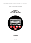
MT-RX-5
AIS DUAL CHANNEL
COLLISON AVOIDANCE RECEIVER
User Manual
Page 1 of 31
© Micro Technologies (NZ) Limited, 2014 – MT-RX-5 User Manual v1.0.7 – v1.84 Firmware
Table of Contents
Introduction..........................................................................................................................................4
Getting Started......................................................................................................................................6
TO TURN ON:............................................................................................................................6
TO TURN OFF:..........................................................................................................................6
AIS Screens..........................................................................................................................................7
GPS Screen ........................................................................................................................................10
DF Screen...........................................................................................................................................11
Alert Operation...................................................................................................................................11
Sequence of events when an alert is processed:........................................................................12
MT-RX-5 Configuration.....................................................................................................................13
Alerts Sub Menu............................................................................................................................14
AIS-SART.................................................................................................................................14
AIS PROXIMITY.....................................................................................................................14
AIS COLLISION......................................................................................................................15
GPS ANCHOR..........................................................................................................................15
RELAY TIME...........................................................................................................................15
SOUNDER TIME ....................................................................................................................15
DUP REJECT TIME ................................................................................................................15
System Sub Menu..........................................................................................................................16
LANGUAGE............................................................................................................................16
BACKLIGHT............................................................................................................................16
SOUND.....................................................................................................................................16
RS422........................................................................................................................................16
AUTO SHUTDOWN................................................................................................................16
RS232 BAUD...........................................................................................................................17
MAIN SCREEN........................................................................................................................17
FACTORY.................................................................................................................................17
TEST.........................................................................................................................................17
DF Sub Menu.................................................................................................................................18
WAYPOINT TARGET..............................................................................................................18
WAYPOINT LAT......................................................................................................................18
WAYPOINT LONG..................................................................................................................18
VOICE REPEAT.......................................................................................................................18
BEARING.................................................................................................................................18
DEF POSITION........................................................................................................................19
DEF LAT...................................................................................................................................19
DEF LONG...............................................................................................................................19
DEF HEADER..........................................................................................................................19
AIS Sub Menu...............................................................................................................................20
COLLISION..............................................................................................................................20
PROX ALERT...........................................................................................................................20
PROX WARN...........................................................................................................................20
DISPLAY..................................................................................................................................20
RS232 OUT...............................................................................................................................20
AIS Collision Avoidance....................................................................................................................21
AIS SART Transmission Logging......................................................................................................22
GPS Anchor........................................................................................................................................22
Page 2 of 31
© Micro Technologies (NZ) Limited, 2014 – MT-RX-5 User Manual v1.0.7 – v1.84 Firmware
Target Setting......................................................................................................................................23
Installation..........................................................................................................................................26
Connecting to the MT-RX-5..........................................................................................................27
Aerial Elevation.............................................................................................................................27
MT-RX-5 Customisation....................................................................................................................29
Disclaimer...........................................................................................................................................29
Specification.......................................................................................................................................30
Manufacturer Declaration of Conformity...........................................................................................31
Page 3 of 31
© Micro Technologies (NZ) Limited, 2014 – MT-RX-5 User Manual v1.0.7 – v1.84 Firmware
Introduction
The Micro Technologies' MT-RX series decoders are true multi-band receivers. They have been
designed primarily for the purpose of decoding emergency signals and then to provide an alert to
locate the source of the transmission for the purposes of early rescue. By default the receiver is
housed in a heavy weight, robust PDL 56 series polycarbonate enclosure, with thick aluminium
front plate and waterproof seals – either as fixed or portable variants. The unit is well suited for
panel mounting and a flush panel mount kit is available to purchase separately (that also allows for
an integrated GPS module to be used).
The MT-RX-5 operates multiple independent DSP (Digital Signal Processing) receivers
concurrently allowing the simultaneous decoding and alerting of several distress signal types over
many different frequencies.
Primarily the MT-RX-5 has been developed to provide an alert and simple direction indicating
capability for AIS based SART alerting devices operating on both 161.975MHz and 162.025MHz,
but performs equally well as a general AIS receiver.
AIS receiving and processing features include:
• Dual -115dBm receivers.
• Clear man-overboard alerts, and time stamped logging to SD card.
• Graphical and text based local vessel display.
• Proximity alerts and warnings.
• Configurable collision avoidance alerts.
Page 4 of 31
© Micro Technologies (NZ) Limited, 2014 – MT-RX-5 User Manual v1.0.7 – v1.84 Firmware
•
•
GPS anchor alerts.
RS232 Serial output for connection to PC based mapping tools.
AIS alerts can be logged to internal memory storage, and provide a time-stamped history of alert
location and activity. The file history can be viewed on the MT-RX and any logged transmission
can be set as a target that provides a bearing and distance to the transmission source.
The on-board relay can be connected to external alerting devices, and the internal sounder provides
alerts and voice prompts for “voice only” guidance to selected targets.
The high visibility graphic display provides clear details relating to the alert and when GPS
information is available provides a clear bearing and distance to any selected target transmission.
Logged information can be viewed on the MT-RX itself and retrieved by connecting to the USB
port (of the MT-RX – internal access only), or by removing the SD card with care and inserting into
a micro SD card reader.
RS232 output can be configured to allow integration with PC based mapping tools.
MT-RX Receivers are also offered as a waterproof portable option, allowing up to 15 hours of use
from non-rechargeable batteries. Portable MT-RX receivers use an internal GPS module and can
provide distance and direction information to a AIS beacon location. MT-RX portable receivers are
described by the use of the suffix 'P' e.g. MT-RX-5-P (Portable AIS).
The MT-RX-5-P is a simple, transportable and affordable AIS solution, that requires no wiring and
may be used with the supplied telescopic aerial or an elevated fixed aerial.
MT-RX-5-P Portable AIS Receiver
Page 5 of 31
© Micro Technologies (NZ) Limited, 2014 – MT-RX-5 User Manual v1.0.7 – v1.84 Firmware
Getting Started
MT-RX receivers are available as portable and fixed options. When provided as a fixed receiver the
MT-RX will begin to operate normally as soon as power is applied, and as long as an aerial is
attached and connected to a suitable power source will be able to respond to alert conditions.
MT-RX portable receivers remain in a zero power initial state until deliberately turned on and will
remain on until powered off, or until the auto shut-down feature operates.
TO TURN ON:
Briefly press the bottom square button.
TO TURN OFF:
Press and HOLD the bottom square button for approximately 5 seconds. After 2 seconds the MTRX will advise that that the unit will shut-down. Once shut-down the MT-RX will use zero power.
Page 6 of 31
© Micro Technologies (NZ) Limited, 2014 – MT-RX-5 User Manual v1.0.7 – v1.84 Firmware
AIS Screens
The top level AIS screen defaults to the graphical vessel summary, providing details of vessels
within the area and direction of travel. AIS target and collision avoidance status can be viewed on
this screen.
From this top level screen, pressing the right button cycles though each technology specific
summary screen. While on each screen, pressing the up button cycles through sub screens for each,
providing access to logged results, live data as received and additional parameters.
The vessels shown on the top level AIS screen are as follows:
Stationary vessel
Moving vessel, indicating direction.
Vessel expected to collide based on collision alert configuration (flashing).
Vessel set as a target (for direction finding using the DF screen).
Vessel that has not transmitted data in the last minute.
Page 7 of 31
© Micro Technologies (NZ) Limited, 2014 – MT-RX-5 User Manual v1.0.7 – v1.84 Firmware
The AIS vessel list screen provides an ordered list of the closest vessels, updated as new
transmissions are decoded. The last transmission from each vessel can be selected to provide
additional information such as current location. Any vessel on this screen can be selected as a target
by pressing the square button, allowing the Direction Finding (DF) screen to to used.
The SART (Search and Rescue Transponder) screen provides information relating to AIS distress
type transmitters operating on both 161.975MHz and 162.025MHz. These transponders are
commonly used as man-overboard transmitters.
Information decoded on this screen is logged directly to SD card, and can be used to set as a target
for direction finding to.
Page 8 of 31
© Micro Technologies (NZ) Limited, 2014 – MT-RX-5 User Manual v1.0.7 – v1.84 Firmware
The AIS raw data screen displays decoded AIS packets from both channels in real time. The MTRX-5 can be configured to output this data out the RS232 connector, that can then be used by PC
based AIS mapping tools. All AIS single and double sentence messages are decoded. Variable
length AIS messages are decoded up to a length of 2 sentences (AIS transmissions greater than 2
sentences are rare).
The decode history sub screen provides a means to view time-stamped entries, and also allows the
entries to be selected to used with the direction finding screen (see Target Setting). Only AIS-SART
messages are listed in the history.
Page 9 of 31
© Micro Technologies (NZ) Limited, 2014 – MT-RX-5 User Manual v1.0.7 – v1.84 Firmware
GPS Screen
The GPS screen provides details of the GPS data that is provided to the MT-RX-5 for direction
finding. If the GPS anchor feature is currently in use, the distance from the anchor set location is
shown – see “GPS Anchor”.
The GPS raw data sub screen provides real time updates of provided GPGGA and GPRMC NMEA
sentences that are used to determine the current location, quality of fix and time.
Page 10 of 31
© Micro Technologies (NZ) Limited, 2014 – MT-RX-5 User Manual v1.0.7 – v1.84 Firmware
DF Screen
The DF (direction finding to target) provides an indication of the current target that has been
selected, bearing and distance to that target. The operation and use of the DF screen is better
described in the “Target Setting” section. While in this screen voice prompts can be enabled to
allow direction finding to the target without the need to look at the screen.
The DF screen allows direction finding to AIS transmissions, and also to manually entered
waypoints.
Alert Operation
The MT-RX-5 can be configured to raise an alert through the on-board relay or sounder under a
variety of conditions. The duration of sounder operation and relay operation can be independently
configured via the alert menu system.
AIS alerts can be raised for transmissions that are:
•
Type 1 messages, status 14 (SART active)
•
Type 1 messages, status 14 plus status 15 (SART test).
•
Within a configured distance, providing a simple proximity alert. Separate “warning” and
“alert” distances can be configured.
•
Determined to be on a collision course, based on direction of travel, speed and safe area
distances configured – see “Collision Avoidance”.
GPS Anchor alerts can be raised when moving outside the safe anchor radius for a set location.
Page 11 of 31
© Micro Technologies (NZ) Limited, 2014 – MT-RX-5 User Manual v1.0.7 – v1.84 Firmware
Upon reception of a configured alert message type, the relay is closed for the configured period of
time (set via the alert menu system) and the sounder operates independently for a configured period
of time (heard through internal speaker).
Sequence of events when an alert is processed:
1. Relay Operates (for configured period of time).
2. Sounder Operates (for configured period of time).
3. The display shifts to the AIS decode screen (except if already on the DF (direction find to
target) screen).
4. An alert pop-up to indicate a new alert is displayed (if this is a new alert).
If there is an ID and location available for the alert :
5. The decoded alert message is logged to SD Card.
6. The ID of the alert (AIS MMSI) is stored.
7. The configurable duplicate reject timer is started (preventing the same ID raising another
alert until a period of inactivity has elapsed).
8. If not already on the DF screen, the ID and location of the alert ID is automatically set to
the active tracking target ID (but will not automatically shift to this screen).
When any key is pressed the sounder will cease and the relay will open.
Page 12 of 31
© Micro Technologies (NZ) Limited, 2014 – MT-RX-5 User Manual v1.0.7 – v1.84 Firmware
MT-RX-5 Configuration
At any time the “MENU” button can be pressed that will enter the configuration menu. The
receivers continue to operate normally and can raise alerts while in the menu system.
At any time the active buttons that may be pressed are shown on the screen, such as the “MENU”,
“UP”, “DOWN” and “RIGHT” buttons. Using the above screen as an example, pressing the
“RIGHT” button will enter the “ALERTS” sub menu. When reaching any configuration item,
pressing the “RIGHT” button again will highlight the item to change.
Once inside the menu, pressing the “MENU” button again will go back up one level until the menu
mode is exited. All configuration changes are written to file only when leaving menu mode.
Page 13 of 31
© Micro Technologies (NZ) Limited, 2014 – MT-RX-5 User Manual v1.0.7 – v1.84 Firmware
Alerts Sub Menu
AIS-SART
Items ACTIVE ONLY and ACTIVE+TEST can be selected.
ACTIVE ONLY:
Only AIS type 1 messages status 14 transmissions will activate an alert and close the relay. All test
transmissions are logged and displayed, but will not raise an alert.
ACTIVE+TEST:
Both AIS type 1 messages status 14 transmissions AND status 15 test transmissions will result in an
alert being raised.
AIS PROXIMITY
Allow generation of warnings and alerts for the distances configured in the AIS menu.
Items ENABLED+WARN, WARN ONLY, DISABLED and ENABLED can be selected.
ENABLED:
When selected, when any AIS transmission that is determined to be less than the configured PROX
ALERT DIST will result the relay and sounder operating.
ENABLED+WARN:
In addition to the same functionality as the ENABLED setting, this setting also provides an short
duration audible warning and screen pop-up when any AIS transmission that is less than the
configured PROX WARN DIST distance.
WARN ONLY:
When selected, upon reception of any AIS transmission that is less than the configured PROX
WARN DIST will result in a short duration audible warning and screen pop-up. This setting will
result in the relay NOT closing.
Page 14 of 31
© Micro Technologies (NZ) Limited, 2014 – MT-RX-5 User Manual v1.0.7 – v1.84 Firmware
DISABLED:
No AIS proximity alerts or warnings will be generated.
AIS COLLISION
Allows the generation of collision alerts based on the settings configured in MENU->AIS>COLLISION.
Items ENABLED and DISABLED can be selected. See “AIS Collision Avoidance”
GPS ANCHOR
Sets the allowed travel distance before raising an alert. Distances from 5 – 500 meters can be set.
The GPS Anchor feature is set from the GPS main screen, not in the menu – see “GPS Anchor”
RELAY TIME
The time in seconds that the relay will close for when an alert is raised. Pressing any button after an
alert is raised will result in the relay opening again. The relay will be able to operate again after the
source of the alert has been absent for the DUP REJECT TIME.
SOUNDER TIME
The time in seconds that the on-board sounder will operate for when an alert is raised. Pressing any
button after an alert is raised will result in sounder operation ceasing.
DUP REJECT TIME
The duplicate reject feature determines the period of time that must pass before an alert of the same
ID or type will raise an alert again. Typically alert transmissions are sent every minute. Raising a
new alert that needs cancelling again every minute when tracking an alert is not typically desirable.
When the feature is set to a non-zero value a duplicate reject timer is restarted each time the same
ID is received. If the transmission source was to cease for this period of time, then restart, a new
alert would be raised. When set to 0, the feature is disabled and a new alert is raised for each
transmission. The duplicate reject applies to AIS SART and PROXIMITY alerts.
Page 15 of 31
© Micro Technologies (NZ) Limited, 2014 – MT-RX-5 User Manual v1.0.7 – v1.84 Firmware
System Sub Menu
LANGUAGE
The currently used language. Currently only English and Spanish are included. Please advise if
you require translations for another language.
BACKLIGHT
This is the time in seconds that the backlight stays on for after each key press. The backlight may
be set between values of 0 and 30. A value of 0 results in the backlight being disabled, a value of 30
results in the backlight being permanently on.
SOUND
Setting to OFF prevents the sounder from operating and disables all system sounds except when an
alert is raised.
RS422
Allows the use of the RS422 module at 4800 baud when ENABLED. Any expansion board fitted
on the connector that locates the RS422 module may no longer operate correctly if this option is
enabled. The RS422 module may be required in order to interface to NMEA systems.
AUTO SHUTDOWN
This option should only be used when using portable MT-RX systems, or when considerable power
savings are required. When enabled, this setting is the time in minutes that the unit will completely
powered down after there has been no keypress activity.
Page 16 of 31
© Micro Technologies (NZ) Limited, 2014 – MT-RX-5 User Manual v1.0.7 – v1.84 Firmware
RS232 BAUD
Sets the baud rate of the RS232 port to either 2400, 4800, 9600 or 38400 N:8:1. This is the port that
is used to output NMEA messages for use for PC applications or navigation equipment. This port is
also used to accept an external GPS source that allows time to be set and distance to alerts to be
determined.
MAIN SCREEN
This allows any page on any main screen to be set as the default main screen. This results in this
screen being the screen that is first seen when powering up the unit, or after a period of inactivity
the MT-RX will automatically revert to this screen.
Setting to DEFAULT will unset the last custom set screen and will return to the factory default main
screen. Setting to USER SET will set the screen to be the screen that was last used before entering
the menu.
FACTORY
Tools for factory calibration and testing purposes only.
TEST
Allows testing of the unit by generating test messages as if they had been decoded by the unit under
normal operating conditions. If a “AIS-TEST” test is performed, and the unit has been configured
to ignore test transmissions, then there will be no change to the unit behaviour.
Pressing the RELAY option provides a simple method to check relay operation.
Pressing WAVE allows testing of wave files from the SD card.
Page 17 of 31
© Micro Technologies (NZ) Limited, 2014 – MT-RX-5 User Manual v1.0.7 – v1.84 Firmware
DF Sub Menu
WAYPOINT TARGET
When enabled the DF screen uses the WAYPOINT LAT and WAYPOINT LONG settings to
navigate to. It is not possible to permanently enable this setting and is reset after being activated.
Reset of this option is to ensure that normal preference on startup is to set a target to a new AIS
alert, not a previously set waypoint that may not longer be current.
WAYPOINT LAT
Waypoint latitude to use when the WAYPOINT TARGET is enabled. This setting is stored with
other configuration data, but not actively used unless the WAYPOINT TARGET has been enabled.
WAYPOINT LONG
Waypoint longitude to use when the WAYPOINT TARGET is enabled. This setting is stored with
other configuration data, but not actively used unless the WAYPOINT TARGET has been enabled.
VOICE REPEAT
This setting controls how frequently the voice prompt operates that provides a bearing and distance
to the selected target. If the system sound is disabled, then the voice prompt will not be heard.
Setting to 0 disables the voice repeat frequency.
BEARING
Items RELATIVE and TRUE can be selected. The relative setting will generate the “Relative
Bearing to Target...” voice prompt. The bearing is expressed as 0 - 360 degrees relative to the
current direction of travel.
The TRUE setting provides the “True Bearing to Target...” voice prompt. This bearing is relative to
Page 18 of 31
© Micro Technologies (NZ) Limited, 2014 – MT-RX-5 User Manual v1.0.7 – v1.84 Firmware
true north.
DEF POSITION
When ENABLED the MT-RX-5 will use the configured default latitude, longitude and heading
until a externally provided GPS position has been provided. This means that if the MT-RX-5 is
used in a fixed position, such as in a building or oil rig, the heading and distance to an alert can be
determined without the need to connect an external GPS source.
DEF LAT
Default Latitude for use when the default position is enabled.
DEF LONG
Default Longitude for use when the default position is enabled.
DEF HEADER
Default heading for use when the default position is enabled.
Page 19 of 31
© Micro Technologies (NZ) Limited, 2014 – MT-RX-5 User Manual v1.0.7 – v1.84 Firmware
AIS Sub Menu
COLLISION
Allows all collision avoidance parameters to be set – see “Collision Avoidance”
PROX ALERT
Defines a vessel “safe distance” from the current position before raising an alert (note that
proximity alerts must also be enabled in the ALERTS menu).
PROX WARN
Defines a vessel “safe distance” from the current position before raising an warning. A warning is a
lesser audible alert and does not operate the relay. (note that proximity alerts must also be enabled
in the ALERTS menu).
DISPLAY
Setting to SART ONLY will result in ONLY AIS type 1 status 14 and 15 messages being displayed
on the summary screen. Setting to ALL displays all AIS messages on the summary screen. This
setting does not affect the ability to raise an alert or use any AIS feature.
RS232 OUT
Setting to ENABLED outputs all SINGLE sentence AIS messages out the RS232 port at the rate
configured by the SYSTEM baud rate. This output can be used by navigation equipment that can
accept standard “!AIVDM” NMEA style messages. The system baud rate typically should be
configured to be 38400 baud if this feature is used.
Page 20 of 31
© Micro Technologies (NZ) Limited, 2014 – MT-RX-5 User Manual v1.0.7 – v1.84 Firmware
AIS Collision Avoidance
The collision avoidance system is a highly configurable feature that allows alerts to be raised should
a collision condition arise.
If a vessel that is transmitting AIS data remains stationary and the MT-RX is moving towards the
vessel or the vessel continues on a collision course, then an alert can be raised.
In order to use the collision avoidance system:
1. Enable the collision avoidance alert from the ALERTS menu.
2. Configure the collision avoidance system found in MENU->AIS->COLLISION.
3. Set the TEST RADIUS. This is how far from the current location that vessels are evaluated
for a collision condition. Setting the TEST RADIUS to a very large value such as 20 KM
may not add any value and would result in unnecessary false alerts – unless perhaps if
accidentally anchoring in a shipping lane.
4. Set the SAFE RADIUS. Should a vessel be allowed to continue on its current course (or the
vessel that the MT-RX is part of) and the vessels may intersect within the SAFE RADIUS,
then an alert may be raised.
5. Set the WARN TIME to define how long in advance an alert should be given. Having
considered the speed and direction of the vessels, this setting is the prior notice that will be
given before a vessel enters the SAFE RADIUS. NOTE: if the TEST RADIUS is very
small, and the speed of the vessel if very high, then the full configured WARN TIME may
not be possible.
As with the TEST RADIUS, setting WARN TIME to a very large value, such as 60 minutes,
may result in many unnecessary false alerts.
Page 21 of 31
© Micro Technologies (NZ) Limited, 2014 – MT-RX-5 User Manual v1.0.7 – v1.84 Firmware
AIS SART Transmission Logging
All message type 1 status 14 and 15 messages are logged to SD card. Logging is performed for all
messages of the configured alert type regardless of whether they are duplicates.
All AIS data is stored to the file AIS-DAT.CSV and logged in the format:
#16:25 00/00,548206000,-43.6050 172.7154,!AIVDM,1,1,,2,18:kmd>000<F`>IW38j:O6522000t0,4*57
where each entry begins with the '#' character, followed by time and date, SART ID (usually
MMSI), position and full legal AIS type 1 message that generated the alert.
GPS Anchor
The GPS Anchor allows for an alert to be raised when a GPS position has been set and then the
vessel drifts from that set location.
To use the GPS Anchor:
1. In MENU->ALERTS->GPS ANCHOR set how far the MT-RX is allowed to “drift” before
raising an alert. This setting is saved, and needs only to be configured once.
2. Enable the GPS Anchor. This can only be performed from the GPS screen and if there is a
current GPS fix available. From the GPS screen press the square button.
Pressing the square button again will unset the GPS anchor, and allow a new position to be set when
the square button is pressed again.
The GPS ANCHOR field on the GPS screen will now display the distance in meters from the the set
position and confirms that the GPS anchor feature is active. Removing power to the MT-RX, then
applying power again will result in the GPS anchor alert being cleared.
Page 22 of 31
© Micro Technologies (NZ) Limited, 2014 – MT-RX-5 User Manual v1.0.7 – v1.84 Firmware
Target Setting
The MT-RX-5, when a GPS position is presented via internal or externally supplied NMEA
sentence, can provide a bearing and distance to a specified target. When the MT-RX-5 is first
powered on, the target is unset. Viewing the DF screen (direction find to target) the status “NO
TARGET” will be shown.
If the current location is unknown through the absence of a NMEA RMC sentence, then
determination of distance and bearing to target is not possible (unless a DF default position has been
configured through the menu). When a distress message (AIS SART) that matches the alert
configuration settings for the MT-RX-5 (that would result in an alert being raised) is received the
target and the target is currently unset, the target will automatically be set to the ID of that alert
(even if the alert does not provide a position). When an alert is activated the “ALERT” pop-up is
shown, and the active screen moves to the AIS SART screen.
Manually moving to the “DF” screen will show the bearing and distance to the target only if the
current location is known AND the AIS transmission has provided a valid position.
Optionally a waypoint can be manually entered through the menu system (MENU->DF). Any
waypoint can be entered that will then be shown as a DF target of “WAYPOINT”.
Page 23 of 31
© Micro Technologies (NZ) Limited, 2014 – MT-RX-5 User Manual v1.0.7 – v1.84 Firmware
When a new alert message is decoded, the target will NOT be updated if the target has a different
ID (but an alert will still be raised). If a new message has the same ID the location of the target will
be updated.
To set a new target the square “ENTER” button must be pressed while on the AIS SART, AIS vessel
list or AIS SART log screens. Using this method it is possible to browse through the file history of
decoded AIS messages and set any of those messages as a new target.
To Set a Target To Last AIS SART transmission:
1. Move to the AIS SART screen.
2. To set this entry as the target now press the “ENTER” button.
3. The pop-up “TARGET SET” will be displayed.
4. The DF screen will now show bearing and distance to this new target.
To Set a Target to a Particular Vessel:
5. Move to the AIS vessel list screen. Highlight the vessel of interest.
6. To set this entry as the target now press the “ENTER” button.
7. The pop-up “TARGET SET” will be displayed.
8. The DF screen will now show bearing and distance to this new target.
To Set a Target From File:
1. Move to the AIS screens.
2. Press the “UP” button until the log screen is shown.
3. Press the “DOWN” button to select the ID of the transmission to VIEW (target has not been
set yet).
Page 24 of 31
© Micro Technologies (NZ) Limited, 2014 – MT-RX-5 User Manual v1.0.7 – v1.84 Firmware
4. Press the square “ENTER” button.
9. The screen will automatically move to the top level display screen and show details for that
file entry (showing the record number at the top instead of the current time).
10. To set this entry as the target press the “ENTER” button.
11. The pop-up “TARGET SET” will be displayed.
12. The DF screen will now show bearing and distance to this new target.
While on the target screen periodic voice messages will be announced indicating the distance and
required bearing to target.
Page 25 of 31
© Micro Technologies (NZ) Limited, 2014 – MT-RX-5 User Manual v1.0.7 – v1.84 Firmware
Installation
The MT-RX-5 should be situated away from direct sunlight, extreme vibration and heat sources,
and high power transmission sources.
An external aerial correctly designed to operate at 162MHz will result in best performance. Do not
situate the aerial immediately next to the aerial of a high power transmission source – position
greater than 2 M from any other aerial. Mount the external aerial with as much elevation as
possible for best results (see “Aerial Elevation” below).
Maximum tolerated input power into the decoder BNC connector is 17dBm. Connecting directly to
a high power source will result in certain damage (e.g. a shared VHF aerial used by a marine radio).
MT-RX receivers can be mounted using the optional MT-RX mounting kit. The use of the stainless
steel mounting kit will ensure that extra holes are not required and therefore decrease the chance of
water ingress.
MT-RX-5 with stainless steel mounting kit fitted
Page 26 of 31
© Micro Technologies (NZ) Limited, 2014 – MT-RX-5 User Manual v1.0.7 – v1.84 Firmware
Connecting to the MT-RX-5
The MT-RX-5 is supplied pre-wired to 2M of 6 core cable into a 6-way screw terminal connector
strip. The MT-RX-5 should not need to be opened unless advised to do so for the purposes of
performing a firmware update or removal of SD card.
Position
Colour
Description
1
RED
+12V DC
2
BLACK
GND
3
BLUE
RS232 in
4
GREEN
RS232 out
5
YELLOW
RELAY common
6
WHITE
RELAY normally open
The minimum required connections for a usable system:
1. Connection to an aerial.
2. Connection to a voltage source.
Optionally the MT-RX may also connect to:
•
An external GPS source.
•
A chart plotter or navigation system (that can also be a GPS source).
•
A PC based mapping system.
•
External sounder controlled via the on-board relay.
•
External speaker.
Aerial Elevation
As with any radio receiver, raising the height of either the transmitter or receiver aerial will result in
dramatic improvements to the maximum possible receive distance. The installed height of the
receiver aerial is the key to a high performing system.
Page 27 of 31
© Micro Technologies (NZ) Limited, 2014 – MT-RX-5 User Manual v1.0.7 – v1.84 Firmware
When close to the ground the major obstacle to overcome, since radio signals are mainly “line of
sight”, is the curvature of the earth. The typical distance to expect (and from testing also
conservative) can be approximately calculated as follows:
distance = sqrt(12.76 X height)
where:
distance is in kilometres and height is the aerial elevation in metres.
Therefore:
1 metre elevation will have the approximate range of 3.5 kilometres.
5 metres elevation , range 8 kilometres.
100 metres (perhaps on a hill) , range 35 kilometres.
Page 28 of 31
© Micro Technologies (NZ) Limited, 2014 – MT-RX-5 User Manual v1.0.7 – v1.84 Firmware
MT-RX-5 Customisation
The MT-RX-5 has been developed by Micro Technologies (NZ) Limited, and therefore if a specific
requirement exists, customisation of Micro Technologies products may be possible (at additional
cost).
Examples of possible customisation:
–
Changes to enclosure.
–
Changes to serial output to better suit specific navigation equipment.
–
Decryption of data parameters (for military use).
–
Support of additional protocols.
–
Support for different Languages.
Disclaimer
THE RESPONSIBILITY LIES COMPLETELY ON THE USER TO ENSURE THAT THIS
DEVICE IS TESTED, THROUGH METHODS THAT ARE APPROPRIATE, TO CONFIRM
THAT ALL SYSTEM COMPONENTS (THAT THIS DEVICE AND PC SOFTWARE MAY BE
PART OF) ARE WORKING CORRECTLY.
THIS DEVICE AND SOFTWARE ARE NOT INTENDED TO BE USED AS A PRIMARY LIFE
SAVING TOOL, BUT MAY BE USED TO STRONGLY COMPLEMENT OTHER EMERGENCY
DETECTION TOOLS ONLY WHEN CORRECTLY CONFIGURED AND TESTED.
The default enclosure for this device is rated IP65, however this rating depends on mounting the
unit using suitable hardware or sealants appropriate to the expected conditions of use. It is the
responsibility of the user to periodically inspect the unit for damage or the lifting of any seals or
labels that may result in the ingress of water. All reasonable care must be taken to ensure that cable
glands and enclosure screws are tight to ensure a waterproof seal.
This document has been prepared in good faith and produced to assist in the use of this product,
however Micro Technologies (NZ) Limited reserves the right to modify, add or remove features
without notice.
Page 29 of 31
© Micro Technologies (NZ) Limited, 2014 – MT-RX-5 User Manual v1.0.7 – v1.84 Firmware
Specification
Enclosure
Plastic. Die cast aluminium or panel mount options
available on request. Stainless steel enclosure
surface mounting kit available.
Supply Voltage
12V. Other voltages available on request (between 6
and 16V).
Relay Contacts
1A . Maximum voltage 24V. Externally connected
inductive loads (such as contactor coils) should use
flyback diodes or snubber circuits.
Relay Closure
•
•
•
•
On AIS type 1 SART status message 14 or
15.
On AIS vessel proximity.
On AIS vessel collision alert.
On GPS Anchor drift alert.
Temperature Limits
-30 to + 55 degrees Celsius.
AIS (A) MHz Receiver Sensitivity
-115 dBm
AIS (B) MHz Receiver Sensitivity
-115 dBm
Receiver Absolute Maximum Input Power
+17dBm.
Aerial Connector
BNC
Operating Current
110mA plus:
18mA when relay energised.
50mA when sounder operating (typical)
40mA when backlight enabled.
Firmware
Field upgradable.
SD Storage Capacity
2GB – or microSD any size.
Serial Output
AIS sentences output as RS-232. RS-422 (for direct
integration with NMEA equipment) support through
internal optional module.
AIS Decode Support
Both 161.975MHz and 162.025MHz. Decoding of
all single and double AIS sentences.
Compliance with Standards:
EN 300 220-2, EN 301 489-3, EN 60950-1 satisfying
the CE directives R&TTE 1999/5/EC, EMC
2004/108/EC and LVD 2006/95/EC.
FCC part 15 Subpart A + B.
Testing Laboratory
EMC Technologies (NZ) Limited. Test reports
131112.1, 131112.2 and 131112.3
IP Rating
IP65 Splash-proof, not to be submerged
Page 30 of 31
© Micro Technologies (NZ) Limited, 2014 – MT-RX-5 User Manual v1.0.7 – v1.84 Firmware
Manufacturer Declaration of Conformity
Page 31 of 31


