1
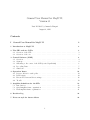
General User Manual for MagIC II,
Version 31
Last Modified by Amanda Zangari
August 4, 2010
Contents
I
General User Manual for MagIC II
2
1 Introduction to MagIC II
2
2 The SITe and e2v CCDs
2.1 Overview of the SITe . . . . . . . . . . . . . . . . . . . . . . . . . . . . . . . . . . . .
2.2 Overview of the e2v . . . . . . . . . . . . . . . . . . . . . . . . . . . . . . . . . . . .
3
3
3
3 Control Software (LOIS)
3.1 Overview . . . . . . . . . . .
3.2 Start-up . . . . . . . . . . . .
3.3 Offsetting to the center of the
3.4 Recording Data . . . . . . . .
3.5 Shutdown . . . . . . . . . . .
. . . . . . . .
. . . . . . . .
CCD (revised
. . . . . . . .
. . . . . . . .
4 Operation Issues
4.1 Rotator offsets for catalog files . .
4.2 LOIS scripts . . . . . . . . . . . . .
4.3 Known Problems and shortcomings
4.4 Trouble . . . . . . . . . . . . . . .
.
.
.
.
.
.
.
.
.
.
.
.
.
.
.
.
.
.
.
.
. . . . . . .
. . . . . . .
April 2008)
. . . . . . .
. . . . . . .
.
.
.
.
.
.
.
.
.
.
.
.
.
.
.
.
.
.
.
.
.
.
.
.
.
.
.
.
.
.
.
.
.
.
.
.
.
.
.
.
.
.
.
.
.
.
.
.
.
.
.
.
.
.
.
.
.
.
.
.
.
.
.
.
.
.
.
.
.
.
.
.
.
.
.
4
. 4
. 4
. 6
. 7
. 13
.
.
.
.
.
.
.
.
.
.
.
.
.
.
.
.
.
.
.
.
.
.
.
.
.
.
.
.
.
.
.
.
.
.
.
.
.
.
.
.
.
.
.
.
.
.
.
.
.
.
.
.
.
.
.
.
.
.
.
.
.
.
.
.
.
.
.
.
.
.
.
.
.
.
.
.
.
.
.
.
.
.
.
.
.
.
.
.
.
.
.
.
14
14
14
18
19
5 Amplifier definitions for the SITe
19
5.1 Introduction . . . . . . . . . . . . . . . . . . . . . . . . . . . . . . . . . . . . . . . . . 20
5.2 Quad-amplifier frame organization . . . . . . . . . . . . . . . . . . . . . . . . . . . . 20
5.3 Dual-amplifier frame organization . . . . . . . . . . . . . . . . . . . . . . . . . . . . . 21
6 Revision Log
22
7 Notes on style for future editors
22
1
List of Tables
1
2
3
4
5
6
7
Standard Filters . . . . . . . . . . . . . . . .
SITe readout time estimates . . . . . . . . . .
e2v readout time estimates . . . . . . . . . .
MagIC II Camera Control Module Inputs . .
FITS header information from TCS . . . . . .
Commands for LOIS Scripts . . . . . . . . . .
Detailed description of LOIS “stdstar” Script
.
.
.
.
.
.
.
.
.
.
.
.
.
.
.
.
.
.
.
.
.
.
.
.
.
.
.
.
.
.
.
.
.
.
.
.
.
.
.
.
.
.
.
.
.
.
.
.
.
.
.
.
.
.
.
.
.
.
.
.
.
.
.
.
.
.
.
.
.
.
.
.
.
.
.
.
.
.
.
.
.
.
.
.
.
.
.
.
.
.
.
.
.
.
.
.
.
.
.
.
.
.
.
.
.
.
.
.
.
.
.
.
.
.
.
.
.
.
.
.
.
.
.
.
.
.
.
.
.
.
.
.
.
.
.
.
.
.
.
.
.
.
.
.
.
.
.
. 3
. 3
. 3
. 8
. 13
. 15
. 17
Part I
General User Manual for MagIC II
1
Introduction to MagIC II
The Raymond and Beverly Sackler Magellan Instant Camera (MagIC II) hosts two CCDs within
the same dewar: a 2k x 2k SITe CCD and a 1k x 1k e2v CCD. NOTE: The e2v frame-transfer
CCD that has not yet been commissioned for general use. The dewar is continuously cooled by a
CryoTiger to hold a detector temperature of -120◦ C. The dewar is mounted to a dual filter wheel
which contains 18 positions for 4-inch square filters, so that 16 filters can be mounted at one time
(there is an open position in each wheel). Both the SITe and the e2v share the same filters. The
standard mounted filters are the Harris B, V, R, I and Sloan u0 , g0 ,r0 , i0 , z0 as well as a custom
VR filter. Both CCDs are run using the Lowell Observatory Instrumentation System (LOIS). Only
one CCD can be operated at a time, and switching between them requires physically swapping
the optical fibers on the instrument computer (rainbow colored wire). Full instructions on how to
switch between them are given in the Mountain Support Manual.
Only an instrument specialist should switch between the SITe and the e2v; this should not be
attempted by the observer.
In 2008, the control software for the e2v was updated to the Lowell Observatory User Interface.
While the original LOIS software should still work, please see the separate User’s Manual for
MagIC-e2v and LOUI for up-to-date information on the e2v.
2
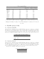
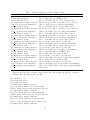
Table 1: Standard Filters
Passband FWHM (Å) Throughputa
Throughput
Mag 1e-/sec extinction coefficient
Harris B
4303
1045
27.13
0.21
Harris V
5430
971
27.17
0.12
Harris R
6393
1524
27.42
0.10
Harris I
8372
2102
26.79
0.04
VRb
6100
836
Sloan u0
3522c
634c
25.09
0.49
0
c
c
Sloan g
4803
1409
27.51
0.09
Sloan r0
6524c
1388c
27.44
0.16
Sloan i0
7668c
1535c
27.17
0.04
0
c
Sloan z
9114
1409c
26.21
0.04
a. Measurements are based on engineering observations taken on 2004 March 8
b. Custom filter for KBO observations, see Jewitt, D., Luu J., & Chen J. 1996 Astron. J., 112,
1225.
c. Fukugita, M., Ichikawa, T., Gunn, J. E., Doi, M., Shimasaku, K., & Schneider, D. P. 1996, AJ,
111, 1748
Filter
2
2.1
Central λ (Å)
The SITe and e2v CCDs
Overview of the SITe
At the f/11 focus of Magellan, the 2k x 2k SITe CCD has a plate scale of 0.069 arc seconds/pixel
(the full field is 2.36 arc minutes square). The read noise in the four quadrants lies in the range
4.5-6.2 electrons, with gains in the range 1.90-2.04 e-/ADU. Table 2 gives the approximate readout
times based on binning and amplifier settings. Note: there may be problems with the binning modes.
Table 2: SITe readout time estimates
Binning Single Amp (sec) Quad Amp (sec)
1x1
73
23
2x2
24
8
4x4
11
2.2
Overview of the e2v
At the f/11 focus of Magellan, the 1k x 1k SITe CCD has a plate scale of 0.037 arc seconds/pixel
(the full field is 40 arc seconds square). The read noise in the left and right amplifiers is 6.0-6.5
electrons, with gains in the range 2.4-2.6 e-/ADU. Table 3 gives the approximate readout times
based on binning and amplifier settings. Note: there may be problems with the binning modes.
The e2v is not currently commissioned for general use.
Table 3: e2v readout time estimates
Binning Dual Amp (sec)
1x1
5
3
3
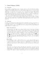
Control Software (LOIS)
3.1
Overview
Data acquisition for MagIC II is carried out using version 4 of the Lowell Observatory Instrumentation System (LOIS). LOIS-4 runs on a Sun computer, magic-site.lco.cl, located in the
equipment room of the Baade telescope. The observer can use either observer workstation in the
Clay control room zorro.lco.cl or guanaco.lco.cl – to run the script “magic”, which will automatically log into magic-site.lco.cl and start LOIS. LOIS can be configured to launch one of
several modules that control various aspects of the system: a telescope interface, a camera interface
(SITe or e2v), an instrument interface (the filter wheel), and a display interface.
The same version of LOIS controls both the SITe and the e2v, with only minor differences
(mostly options for readout modes and binning). Thus the instructions below apply to operating
either camera. The LOIS module to run the SITe is called magic and the module to run the e2v is
magiceiiv.
3.2
Start-up
Normally, an the instrument specialist will already have MagIC II set up and your data directory
for the night created. If so, the only remaining step you need to take before taking data is to copy
your scripts, if any (see §4.2), to the LOIS home directory using the FTP program Transmit. If
LOIS is running, you can skip to §3.3.
• Make a data directory.
An internal disk on the magic-site computer, intended only for data storage, is mounted
as /data on magic-site.lco.cl. Create a directory under /data for the night’s data. This
is temporary data storage and should be erased at the end of each run. To transfer data
between the magic-site computer and guanaco or zorro, use the MAGIC shortcut inside
Transmit. No password is required. You should copy your data over to /Data Zorro or
/Data Guanaco, where it can be stored during your run. (A useful feature for keeping the
/Data Zorro directory up to date during the night is the “Synchronize” button in Transmit.)
The observer machines have DVD drives that you can use to create a copy of your data for
transport home.
• Start LOIS.
Before starting the software, confirm with the telescope operator that the CCD electronics
for either the SITe or the e2v have been powered on and that the fibers for that CCD are
connected to the PCI card on magic-site.lco.cl. (This should be done as part of the
instrument setup.) From an observer workstation, generate an xterm window. Then run the
startup script:
xterm> magic
There will be some diagnostic messages indicating that old files have been cleaned up. The
startup script will configure the required environment variables and path names, start the
default display tool (ds9), kill any previous LOIS or ds9 processes, and start the main LOIS
program. The display tool window (ds9) will appear on the screen first, followed by the
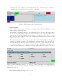
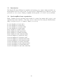
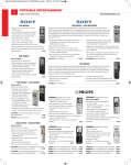
4
“LOIS system console” (Figure 1). The LOIS system console is divided into two windows a
command window on the left and a log window on the right.
Figure 1: LOIS System Console startup screen.
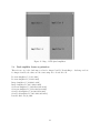
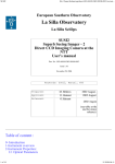
• Open Modules.
In the “LOIS System Console” click on the “Configure” button. This will display the configuration window found in Figure 2.
The standard configuration should be the magellan telescope module, the magic camera
module (for the SITe) OR the magiceiiv camera module (for the e2v), the MagICfilt instrument module and the DS9/XPA display interface. You also have the option to disable
any of these modules. After choosing your configuration, fill in the fields for Observer and
Affiliation and click on “Start.”
The camera, instrument, and telescope modules will be loaded and initialized. This process
can take a few minutes, mostly for the initialization of the filter wheels. Three new GUI elements should appear, which are described in the follow section: a “Camera Control Module”,
an “Instrument Module”, and a “Telescope Control Module”. Information regarding what is
being loaded and what else is occurring can be found in the LOIS Console window log screen.
Figure 2: LOIS configuration window. Set telescope, camera, instrument and display interfaces
here as well as observer information (names and affiliations). Select magic for the SITe CCD and
magiceiiv for the e2v.
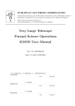
• Set up data storage on magic-site.lco.cl.
5
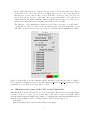
In the “LOIS System Console,” click the “Storage” button. The Storage window (see Figure
3) will allow you to choose the directory on magic-site.lco.cl to save your data in. If
this directory does not exist, it will be created; it should be a directory only one level below
/data. You can also set the root file name and exposure start number. Note that if you
restart LOIS, the file number will skip a number from the last exposure you took in order to
indicate the restart (and avoid overwriting data in the event of a crash).
The disk space on the instrument computer is recycled after each run, so you will want to
copy the files to a directory on the observer workstation and to removable media that you can
take with you when you leave. If you need help in doing this, ask the instrument specialist.
Figure 3: In this window, set the pathname and file structure for the data and click on “Apply”.
Store your data on magic-site.lco.cl in /data/whatever directory you created. If you type
a path that does not exist the directory will be created.
3.3
Offsetting to the center of the CCD (revised April 2008)
With MagIC-II, both the SITe and the e2v are now physically offset from the optical axis. Thus,
each time you move to a new object you must offset to the center of your chosen CCD. This is
currently handled using the IRAF script tomagic. To run this script, first launch an IRAF window
using the Big Red Button on the observing computer. Then load the magic tools:
ecl> magic
Edit the parameter file to indicate which CCD you are using:
6
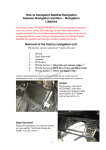
ecl> epar tomagic
Set ccdname to e2v or site. Select yes to send offsets to the telescope control system (TCS)
and no to performing a coordinated offset. Type :q to exit. Run the script any time you move to
a new target:
ecl> tomagic
The magnitudes of the offsets to the two CCDs are constant and have been set in tomagic to
be {50, 5} for the SITe and {-92,6} for the e2v (note that the SITe is in the opposite direction
from the center of the e2v). These values are given in arcseconds along the detector axes, and the
corresponding values in cardinal directions depend on the rotator angle. For example: for the e2v
in EQU 0.0, an object to the south will be offset 9200 W and 600 N, while for the SITe the same
object would be offset 5000 E and 500 N. Which offset to use is determined automatically so long as
the correct CCD is specified in the parameter file. The new offsets should have been updated for
the SITe and e2v when MagIC was brought to the west Nasmyth port.
Figure 4: Parameter file for IRAF script tomagic. Set ccdname to either site or e2v.
3.4
Recording Data
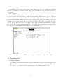
• Camera Control
The camera is controlled through the “MagIC CCD Camera Control” module displayed in
Figure 5. This module is where the observer controls the execution of exposures using either
the “test” or “go” buttons. Table 4 describes each of the inputs for this module.
7
Figure 5: Parameter file for IRAF script tomagic. Set ccdname to either site or e2v.
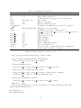
Table 4: MagIC II Camera Control Module Inputs
Description
SITe Quad-, double-, and single amp readouts with gains of 1
(approx 2e/ADU) are available.
e2v Double Amp readout is available.
Binning
SITe 1x1, 2x2, 4x4
e2v 1x1
Number of Exposures Enter the number of exposures in a sequence.
Exp Time
Enter the exposure time in seconds.
Object Title
Enter the object title. This will be entered in the FITS header as Object.
FITS Comments
Provides two comment lines for the FITS header.
Frame Type
Choose the frame type for the FITS header. Object opens the shutter;
Dark and Bias do NOT open the shutter.
Test
Takes the current exposure and writes to the temporary file “test.fits”.
This file will be overwritten by subsequent test images if not renamed.
Go
Takes the current exposure (or sequence) and writes the data to the configured
data directory. These files will not be overwritten on the host machine even
if you use the same filename.
Abort
Abort the current exposure or the current series of exposures.
This does not handle aborting scripts, which must be done from the
LOIS system console. It is safer to abort while the status is Exposing,
or LOIS may crash.
Input
Dector Mode
All information entered into the input fields will be mirrored to the Status window and
recorded in the FITS header. After you choose either “test” or ”go”, a “process bar” (Figure
6) keeps you apprised of what the camera is doing. The process bar is blue while the camera
8
is exposing or reading out the chip. A timer counts down the remaining exposure time and
shows what exposure number is being collected.
Figure 6: MagIC CCD Camera Control status while exposing.
Once an exposure is complete the process bar says “Reading” (Figure 8) until the file is read
out, at which point it briefly says “Storing”. When the system is ready for the next action,
the bar turns green and says “Camera Ready”.
Figure 7: MagIC CCD Camera Control status while reading out.
9
Figure 8: MagIC CCD Camera Control status when ready to take the next exposure.
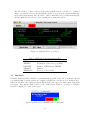
• Displaying Data
All images are automatically displayed to the ds9 window. SAOimage ds9 (Figure 9) is a
standard image display and analysis tool that is fully documented with its own help files.
It is also fully integrated with the IRAF display tools installed on both of the instrument
computers. For modifying the display on future images, the following command may be
entered into the LOIS System Console command window:
LOIS% :
disp set state=on min=XXX max=XXX scale=<log|linear|raw|auto>
It may be helpful to display images in another ds9 window using standard IRAF commands.
See the weblink for “Reducing MagIC Images with IRAF”
(http://www.lco.cl/telescopes-information/magellan/instruments/magic/reducing-magic-imageswith-iraf/reducing-magic-images-with-iraf/) for more details.
10
Figure 9: Sample of ds9 display tool for LOIS.
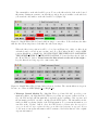
• Instrument module (filter wheel)
The filter wheel is controlled through the “MagIC Filter Wheel Control” window. At startup,
the GUI pops up without specifying filter names. Once initialization, which can take a minute
or two, is complete, the wheel positions should all have the correct filters identified (Figure
10).
Figure 10: MagIC Filter Wheel Control after initialization.
11
The current filter on the wheels will be green. To move the filter wheels, click on the desired
filter name. During movement to another filter position, the previous filter on the wheels is
yellow and the chosen filter on the wheels will be red (Figure 11).
Figure 11: MagIC Filter Wheel Control while moving to a new filter. Yellow indicates the filter
that the wheel is moving from, red the filter the wheel is moving to.
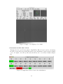
When the filter is in position it will be colored green (Figure 12). Only one filter from
each wheel can be selected at any one time, and one of those filters should be in the OPEN
position (MagIC t0 or MagIC b0). BE SURE THAT THE WHEEL NOT CONTAINING
THE DESIRED FILTER IS IN THE OPEN POSITION. To home the filter wheels, click on
the “Home Wheels” button. Please home the filter wheels at the end of the night to
keep the filters from being exposed to unnecessary dust.
Figure 12: MagIC Filter Wheel Control after selection of a filter. The current filters are in green.
Be sure one of these is OPEN (MagIC t0 or MagIC b0).
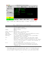
• Telescope Control Module The “Magellan Telescope Control Module” provides a communication link to the Magellan TCS. Whenever you take an exposure (either via Test or
Go), the TCS module will automatically be updated at the beginning of the exposure and
the information in Table 3.4 will be included in the FITS header. The information in the
window is NOT a real time display of the TCS information. To get current information, you
can click on the “Update” button. Since the FITS header is written after the exposure is
over, you should not try to update the telescope module after beginning an exposure. If you
do, the most recent update information will be written to the header instead of the original
exposure information.
12
The “Coord Move” button opens a pop up window which is used to execute a “coordinated
offset” – moving the telescope and moving the guiders so as to keep the guiders tracking the
guide- and wavefront stars. The “Rel Move” button offsets the telescope without moving the
guiders. Make sure the telescope is not guiding before using this button.
Figure 13: Magellan Telescope Control
Table 5: FITS header information from TCS
Header Keyword Definition
TELRA
Right Ascension of the telescope pointing
TELDEC
Declination of the telescope pointing
EQUINOX
Equinox of TELRA and TELDEC
AIRMASS
Airmass
TELFOCUS
Telescope focus readout
3.5
Shutdown
Normally, shutdown will be handled by an instrument specialist at the end of your run. Should
you want the shut down the system (for example, if LOIS has a serious error as discussed in §),
first home the filter wheel (this prevents the filters from being exposed to unnecessary dust when
not in use). Then hit the “Exit” button on the “LOIS Console Window”. A dialog box (Figure
14) will be displayed to verify your request.
Figure 14: Dialog box confirming desire to exit LOIS
13
Remember to REMOVE your data from the host computer magic-site.lco.cl prior to the end
of your observing run, AFTER YOU MAKE A COPY OF THE DATA to the observer computer
guanaco or zorro or elsewhere. The data copy on magic-site.lco.cl is intended as temporary
data storage, not permanent data storage, which should be on your DVD, hard drive or other
media.
4
4.1
Operation Issues
Rotator offsets for catalog files
At the central folded port on the Baade telescope, the rotator angle offsets (which are included in the
.cat files for the telescope operator) for target positions are different that those adopted at the Nasmyth ports. Most observers will chose “0.0 EQU” for columns #8 and #9 of their catalog file that
they give to the telescope operator (see http://www.lco.cl/telescopes-information/magellan/instruments1/observing-catalogs-1 for a full description of the fields required in a catalog file). This will produce
images that are North-right and East-down for southern targets and North-left and East-up for
northern targets.
4.2
LOIS scripts
Note: parts of this section may need updating as of May 2008. Scripts written in Tcl can be written
to take a series of exposures, change filters and move the telescope as needed. For use, scripts should
be added (using the MAGIC shortcut in Transmit) to the top level of the observer home directory
on magic-site.lco.cl, /home/observer, since this is where LOIS will look for active scripts. At
the end of your run, save your scripts elsewhere, and erase them from /home/observer. Some
example scripts are located in /home/observer/SCRIPTS. At important caveat for scripts is that
THEY WORK ONLY FOR THE QUAD-AMP, 1x1 BINNING MODE FOR THE SITe. Scripts
must first be loaded and then run. Both tasks are executed by commands entered in the LOIS
system console command window. To load a procedure in the command window, type:
LOIS% source script file name
To run a script, in the command window type:
LOIS% procedure name
Scripts can be aborted using the red “Abort current script” button on the LOIS system console.
Table 6 describes the command line information necessary in scripts. If a value is not specified it
is assumed to be zero in the case of a floating point input. For example, using delta rot=0 means
that the rotation does not change from whatever it was defined as, but it is not necessary to specify
this in order to keep the same orientation.
14
Table 6: Commands for LOIS Scripts
Options
Definitions and Notes
0 or 1
Top or bottom filter wheel
0–8
Filter position on the wheel
–
Command, starts an exposure, followed by frame=xx
bias, dark, object
Type of frame
float
Number of exposures
float
Exposure duration (seconds)
Command to set amplifiers to use, followed by amp=xx
A,B,C,D,AB,CD,ALL Amplifiers to use, case sensitive
Command to set telescope offset, followed by
delta ra=<float> delta dec=<float> ... delta rot=<float>
delta ra
float
Offset in ra, arcseconds
float
Offset in dec, arcseconds
delta dec
delta az
float
Offset in altitude
delta el
float
Offset in elevation
delta rot
float
Offset in rotation
timeout
int
Integer, default timeout is 90s
-noguide
-noguide
Used for a relative movea
epoch
float
The epoch of the coordinates that you are offsetting from
and is required for an offset w/o guiders.a
a. Note the -noguide and epoch are used in a relative move that is not coordinated with the
guiders. xx what is meant by “epoch” here? xx
Command
filter wheel
pos
go
frame
nexp
etime
set amplifier
amp
offset
How you use the keywords defines the type of offset you want.
• For a coordinated RA and DEC offset with the guiders:
offset delta ra=<value> delta dec=<value>
• With the instrument rotator:
offset delta ra=<value> delta dec=<value> delta rot=<value>
• Offset move in RA and DEC without the guiders:
offset delta ra=<value> delta dec=<value> epoch=<value> -noguide
Add the delta rot value for to include the instrument rotator.
• Offset move in azimuth and elevation:
offset delta az=<value> delta el=<value> delta rot=<value>
Example # 1. stdstar
The following script takes a set of exposures through a series of filters and exposure times. The
script is defined in detail in Table 7.
proc stdstar {} {
filter wheel=0 pos=0
15
filter wheel=1 pos=1
go frame=object nexp=2 etime=5
log_3 {u filter has finished}
filter wheel=1 pos=2
go frame=object nexp=2 etime=5
log_3 {g filter has finished}
filter wheel=1 pos=3
go frame=object nexp=2 etime=5
log_3 {r filter has finished}
filter wheel=1 pos=4
go frame=object nexp=2 etime=5
log_3 {i filter has finished}
filter wheel=1 pos=5
go frame=object nexp=2 etime=5
log_3 {z filter has finished}
filter wheel=1 pos=0
filter wheel=0 pos=2
go frame=object nexp=2 etime=5
log_3 {V filter has finished}
filter wheel=0 pos=3
go frame=object nexp=2 etime=5
log_3 {R filter has finished}
log_3 {stdstar has finished}
}
16
Table 7: Detailed
Script line
proc stdstar {} {
filter wheel=0 pos=0
filter wheel=1 pos=1
go frame=object nexp=2 etime=25
log 3 {u filter has finished}
filter wheel=1 pos=2
go frame=object nexp=2 etime=10
log 3 {g filter has finished}
filter wheel=1 pos=3
go frame=object nexp=2 etime=5
log 3 {r filter has finished}
filter wheel=1 pos=4
go frame=object nexp=2 etime=5
log 3 {i filter has finished}
filter wheel=1 pos=5
go frame=object nexp=2 etime=5
log 3 {z filter has finished}
filter wheel=1 pos=0
filter wheel=0 pos=2
go frame=object nexp=2 etime=5
log 3 {V filter has finished}
filter wheel=0 pos=3
go frame=object nexp=2 etime=5
log 3 {R filter has finished}
log 3 {stdstar has finished}
}
description of LOIS “stdstar” Script
Explanation of command
Define procedure name, open script
Move top filter wheel to OPEN position
Move bottom filter wheel to Sloan u0 filter position
Execute an object frame: 2 exposures, 25 seconds each
Write to LOIS log screen: u filter set has finished
Move bottom filter wheel to Sloang0 filter position
Execute an object frame: 2 exposures, 10 seconds each
Write to the LOIS log screen: g filter set has finished
Move bottom filter wheel to Sloanr0 filter position
Execute an object frame: 2 exposures, 5 seconds each
Write to the LOIS log screen: r filter set has finished
Move bottom filter wheel to Sloan i0 filter position
an object frame: 2 exposures, 5 seconds each
Write to the LOIS log screen: i filter set has finished
Move bottom filter wheel to Sloan z0 filter position
an object frame: 2 exposures, 5 seconds each
Write to the LOIS log screen: z filter set has finished
Move bottom filter wheel to OPEN position
Move top filter wheel to V filter position
an object frame: 2 exposures, 5 seconds each
Write to the LOIS log screen: the V filter set has finished
Move top filter wheel to R filter position
an object frame: 2 exposures, 5 seconds each
Write to the LOIS log screen: the R filter set has finished
Write to the LOIS log screen: the stdstar script has finished
Close script
Example #2 dither The following script sets the filter wheel, takes an exposure, executes a
coordinated offset and takes another exposure.
proc dither {} {
filter wheel=0 pos=0
filter wheel=1 pos=3
go frame=object nexp=1 etime=60
log_3 {r filter position 1 has finished}
offset delta_ra=-10 delta_dec=0 delta_rot=0
go frame=object nexp=1 etime=60
log_3 {r filter position 2 has finished}
offset delta_ra=0 delta_dec=-10 delta_rot=0
go frame=object nexp=1 etime=60
log_3 {r filter position 3 has finished}
offset delta_ra=10 delta_dec=0 delta_rot=0
go frame=object nexp=1 etime=60
17
log_3 {r filter position 4 has finished}
log_3 {dither has finished}
}
Example #3: dither2filter
The following script sets the amplifier to single readout mode then sets the filter wheel, takes
an exposure, executes a coordinated offset and takes another exposure, changes the filter, takes an
exposure, executes a coordinated offset (back to the original position) and repeats the process 3
times.
proc dither2filter {{nexp 3}} {
set_amplifier amp=D
log_3 {set amplifier to single amp D}
for {set i 0} {$i < $nexp} {incr i} {
filter wheel=0 pos=0
filter wheel=1 pos=3
go frame=object nexp=1 etime=60
log_3 {r filter position 1 has finished}
offset delta_ra=-10 delta_dec=-10 delta_rot=0
go frame=object nexp=1 etime=60
log_3 {r filter position 2 has finished}
filter wheel=1 pos=4
go frame=object nexp=1 etime=60
log_3 {i filter position 2 has finished}
offset delta_ra=10 delta_dec=10 delta_rot=0
go frame=object nexp=1 etime=60
log_3 {i filter position 1 has finished}
log_3 {dither2filter has finished}
}
}
4.3
Known Problems and shortcomings
• Aborting exposures and scripts
This can be done only when neither the telescope nor the filter wheel is moving. It is safer to
abort a script when the process bar on the camera module is blue, indicating that the camera
is either exposing or reading out. LOIS may crash if aborted during read out.
• Phantom pixels at row 1991 (single-amp mode) of the SITe
When reading out in single amp mode the software inserts two bogus pixels at row 1991. The
sky data is seen shifted. This can in principle be corrected in software, but in practice it lies
so close to the edge of the field (4 arcseconds) that one may not want to go through the effort.
• Saturation levels for the SITe
18
Note that amplifiers C and D (the top two quadrants in quad amp mode, as viewed in the
SAOimage ds9 window) saturate at about 35K ADU, well before the other two amplifiers (A
and B) reach saturation.
• File numbers
When you restart LOIS after running a series of exposures, the file number skips one: if the
last frame you took in the previous session was 010, the next frame will by default be 012.
Check the Storage button on restart to make sure you have the desired file number. This is
actually a feature, not a bug: a skipped file number indicates that LOIS was restarted.
• Duplicate files (with different file names)
Occasionally LOIS has been noted to write out duplicate files of the same image, so you should
watch for this when taking sequences of the same exposures (including darks and biases!).
The duplicate files will have different numbers. The cause of this bug is unknown. You should
notify the technical staff if it appears.
• Failure to write FITS files
LOIS sometimes fails to write out FITS files with the error:
Error Unable to write the Fits File!! Status=413
Error Unable to Close the Fits File!
If this occurs, you must restart LOIS for it to figure out how to write files properly again, or
else it will hang while trying to write out subsequent exposures. Usually everything works
fine on restart. The cause of this bug is also unknown, and it is somewhat common.
4.4
Trouble
Under ideal circumstances the system will have be started and tested ahead of your observing run
by the instrument specialist, and it will remain ready to be powered for your run. When properly
set up, the operation of MagIC under LOIS has proven reasonably robust. In the case that odd
error messages occur during the startup, simply exit the current LOIS session and run the start
script again. If you still have problems, ask the instrument specialist or telescope operator to
reset the PCI card on the instrument computer (magic-site.lco.cl). If that does not solve the
problem, the instrument specialist or telescope operator will cycle power on the electronics boxes
and reboot the instrument computer.
5
Amplifier definitions for the SITe
LOIS/MagIC Information Document Number: 001
Title: Amplifier Definitions
Author: Brian W. Taylor
Started: 11/04/2005
Last Revised: 08/31/2006
19
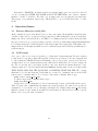
5.1
Introduction
The MagIC SITe 424a CCD has four amplifiers and an image area of 2048 columns and 2049 rows.
Each amplifier when used will generate 20 prescan pixels. With MagIC along with these prescan
pixels there are 40 overscan columns per amplifier and 20 parallel over clocked rows in each frame.
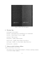
5.2
Quad-amplifier frame organization
Frame organization for the quad amp as shown in the above image demonstrates the location of each
amplifier in the final deinterlace of the image and are defined as follows using the IRAF inclusive
image block [x1:x2, y1:y2] or [column 1:column 2, row 1:row2].
.
Prescan Amplifier A: [1:20,1:1025]
Prescan Amplifier B: [21:40,1:1025]
Prescan Amplifier C: [1:20,1026:2049]
Prescan Amplifier D: [21:40,1:2049]
Image Amplifier A: [41:1064,1:1025]
Image Amplifier B: [1065:2088,1:1025]
Image Amplifier C: [41:1064,1026:2049]
Image Amplifier D: [1065:2088,1026:2049]
Overscan Amplifier A: [2089:2128,1:1025]
Overscan Amplifier B: [2129:2168,1:1025]
Overscan Amplifier C: [2089:2128,1026:2049]
Overscan Amplifier D: [2129:2168,1026:2049]
OverClock Amplifier A: [42:1065,2050:2088]
OverClock Amplifier B: [1066:2089,2050:2088]
OverClock Amplifier C: [42:1064,2090:2128]
OverClock Amplifier D: [1065:2089, 2090:2128]
20
Figure 15: Map of SITe Quad amplifiers
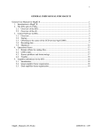
5.3
Dual-amplifier frame organization
This reference is for the dual amp readout for Amps C and D. If switching to dual amp readout
for Amps A and B, the values are the same using A for C and B for D.
.
Prescan Amplifier C: [1:21,1:2049]
Prescan Amplifier D: [21:40,1:2049]
Image Amplifier C: [41:1064,1:2049]
Image Amplifier D: [1065:2088,1:2049]
Overscan Amplifier C: [2089:2128,1026:2049]
Overscan Amplifier D: [2129:2168,1026:2049]
OverClock Amplifier C: [42:1064,2050:2068]
OverClock Amplifier D: [1065:2089,2050:2068]
Last Modified: 08/31/2006
21
Figure 16: Map of SITe dual amplifiers
6
Revision Log
• 2010 August– Revisions finished.
• 2010 July – Split Mountain Support and MIT Support off of main manual.
• 2010 June – Amanda Zangari (conversion to LATEX)
• 2008 April – Elisabeth Adams
• 2008 January – Jim Elliot, Elisabeth Adams
• 2007 November – Jim Elliot, Matt Lockhart, Robyn Sanderson
• 2007 August – Jim Elliot, Steve Kissel, Matt Lockhart, Folkers Rojas
• 2006 September – Susan Kern
7
Notes on style for future editors
Added by Amanda Zangari, June 22, 2010
• The instrument chips are MagIC-SITe and MagIC-e2v. All instances (including emails) have
been corrected to insure consistency.
22
• The following items should be enclosed in typewriter text (aka verbatim): computer names,
file names, and UNIX commands.
• LOIS and LOUI are always referred to in caps (no styling).
• All double quotations marks are to be changed into LATEX-friendly single quotation marks.
23