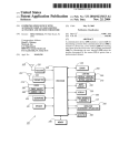
1
Installer Manual A4100 Thermostat Ver 1.0
Switch 8 – Thermostat Control Logic. This switch also has two functions based on the
position of switch 6. When the A4100 is set as a programmable thermostat switch 8
determines whether commercial program or residential program is selected. When
switch 6 has the A4100 used as on programmable thermostat, this switch sets single set
point mode (imitating a simple mechanical thermostat) or whether a separate heating
and cooling set point can be selected by the user. Two set point mode also permits the
user to select a separate day and night set point if required.
FRI
AM
SYSTEM.
TT terminal Functions
Room
OFF
FAN
MED
FAN ON
HOLD
CLOCK SCREEN
This document it not typically left with the user as it contains information on setting
values which, if not correctly set may damage the heating, cooling or air conditioning
system or seriously effect its performance or energy consumption.
Great effort has been taken to making the A4100 thermostat system intuitive, reliable
and easy to install. Using a common sense approach to the installation will ensure this
product is installed easily and to the customer’s satisfaction. Please read and
understand this instruction manual so that installation, testing and commissioning
process is undertaken in an efficient and effective manner.
This manual is to be used in conjunction with the supplied user manual.
Great care has been taken in the preparation of this manual. It is the responsibility of the
user to ensure this thermostat, or the equipment connected to it is operating to their
respective specifications and in a safe manner.
Installation
As with any air conditioning project undertaken, careful installation is the key to a
successful outcome. Time taken during this installation process will be rewarded by a
happy customer and fewer call‐backs.
The steps required to install the A4100 thermostat are
1. Read and understand this manual and the User manual.
2. Mount the A4100 back plate in a suitable location.
3. Set the 8 DIP switches to match the need of the project / user.
4. Wire the optional remote temperature sensor(s) or switches if required.
5. Power up the air conditioning system.
6. Set the installer software options (if required).
7. Program and set up the A4100 thermostat. (The User Manual will assist with this).
8. Test the heating, cooling and other functions – Commissioning.
For convenience the layout of this manual is in the same order as the steps listed above.
Mounting the wall controller
The A4100 can only be as accurate as the onboard temperature sensor, or its optional
remote temperature sensor(s) permit. It is therefore essential that the wall thermostat be
installed in a location that is typical of the ambient room temperature. Do not install the
thermostat in a draft, near a floor, behind doors、 or on a non‐insulated external wall.
Also avoid placing the thermostat in areas where the air movement is limited, affected by
direct sunlight or other areas not “typical” of the temperature of the room.
Further, when mounting the A4100 be aware that drafts may travel down the inside of
cavity walls, (especially if mounted on external walls) and enter the back of the
thermostat or sensor enclosure through the cable entry holes in the wall. It is important
to fully seal these holes to prevent any drafts affecting the internally mounted
temperature sensor. It is recommended to mount the A4100 or remote sensors between
1.5 & 1.7 metres from the floor where possible.
Move the control wires through the large opening in the thermostat base plate then place
the thermostat base on the wall and using appropriate screws, firmly attach the
thermostat base to the wall. Seal any holes where cables enter the back of the
thermostat to prevent drafts entering through these holes affecting he sensor.
Setting the hardware switches
Switch
Sw2 – Equipment Type
Heat Cool
Sw3 – Stages
Sw4 – Reversing Valve
If Sw 2= ON – Heat Pump
Sw4 – Fan Mode
If Sw 2= OFF – Heat/cool
Sw5 – Anti cycle timer
1 Stage
Energise in cool (O)
On
3 Speed Fan (1 heat / 1
Cool)
Heat
Pump
(O/B
terminals)
2 Stages
Energise in heat (B)
Fan Control by Heater
(HG)
Fan Control by T’stat
(HE)
Off
Sw6 – Operation
Manual Thermostat
4 Minutes
Programmable
Thermostat
6 Minutes
Residential Program
Sw1 – Fan Speeds
Off
1 Speed Fan (2 heat / 2
Cool)
Sw7 – Minimum Run
2 minutes
Sw8 – Program Type
Commercial Program
If Sw 6= ON – Programmable
Sw8 – Set points
Single Set point
Two Set points
If Sw 6= OFF – Manual
Typical drawings have been provided on of this manual that will assist with the selection
of the correct positions for these function switches.
Switch 1 – Relay Assignment The A4100 is fitted with 5 relays capable of switching up
to 24VAC @ 1Amp. Switch 1 sets the function as either 3 fan speeds with 1 heat and 1
cool operation or single fan speed with 2 heat and 2 cool, in either HP (Heat pump or
reverse cycle) or HC (heat with add on cool) mode.
Switch 2 – Equipment Type. Both heat with add on cool or heat pump types of systems
can be controlled by the A4100. Heat Cool System uses the “W” terminals only for
heating and the “Y” terminals only for cooling. Heat Pump systems use the “Y”
terminal(s) for BOTH heating and cooling. The “W1” terminal to control the reversing
valve which determines heating or cooling mode.
Switch 3 – Equipment Stages. When it is necessary to control a single stage system
A/C system fitted with auxiliary heating elements, turn sw3 OFF thereby selecting single
stage mode. Heating elements are now called as stage 2 heat (NOT Stage 3 eat).
Switch 4 – Reversing valve or Fan mode When the A4100 is set for Heat Pump mode
(Sw2 is on) then this switch sets the reversing valve logic (O/B). When the A4100 is set
for Heat Cool Mode (Sw2 is off) then this switch sets the mode for the Heater fan logic
(HG or HE mode).
Switch 5 – Anti Cycle Timer To protect some A/C systems it is preferred that under no
circumstances should the compressor start within 4 minutes of it switching off. Note,
when power is first applied to the A4100 it “assumes” that the compressor has just
stopped and applies this anti cycle delay time before starting.
Switch 6 – Thermostat Operation To suit the varying requirements of the user, the
A4100 can be set as a programmable thermostat using the time clock to automatically
control the building temperature to a programmed temperature profile, or to the very
simple to operate manual mode where the user turns the thermostat on or off, and
adjusts the temperature set point manually.
Switch 7 – Minimum Run time. To conserve energy and protect the A/C system it is
recommended to limit the number of times the heating and or cooling system can run in
1 hour. This switch sets the minimum heating and cooling equipment to a minimum run
time of 2 or 6 minutes. Once the heating or cooling has started it must run for this
minimum set time. The LCD will flash the word “Heating” or “Cooling” when ever this
timer is in effect.
The A4100 is fitted with a set of terminals marked “TT”. Detail on the functions that the
“TT” terminals perform is provided below. See the advanced installer setting menu of
this manual for setting the function of this set of terminals. The wiring used in he
following examples are not polarity dependent and do not normally require screened
cable.
NOTE: The A4100 can use multiple sensors if required. Drawings showing these various
on figurations re shown on of this manual.
Outside Air Sensor wiring
Set “TT= OA” in the advanced installer menu.
The A4100 can display the outside air Temperature if
A4100
desired. Some advanced control functions such as high
and low balance points rely Figure 1 on this sensor to
be fitted for correct operation. Using a single pair of
wires connect the “TT” terminals in the A4100 to the two terminals in the outside air
temperature sensor. (See figure 1). If the outside air sensor fails two dashes will be
shown on the LCD where the outside air temperature would normally be displayed to
alert you of the problem.
Remote Air Temperature sensor wiring.
Set “TT= RS” in the advanced installer menu. When
A4100
you wish to measure the temperature from a location
distant from the wall controller, simply connect a remote
temperature sensor to the “TT” terminals in the
A4100. This will automatically disable the sensor fitted
to the wall controller and use the remote temperature
sensor(s) to control the room temperature (See figure 1 above). Should you wish, you
can easily switch the remote temperature sensor on and off thereby switching
temperature sensing locations between the remote temperature sensor and the A4100
temperature sensor when required.
Averaging Temperature sensors
Set “TT= AV” in the advanced installer menu.
The A4100 can average the sensor temperature equally between the remote
temperature sensor(s) and the one fitted to the A4100 if required. See figure 1 on the
previous for details on wiring the sensor. The A4100 will auto‐detect this sensor and
automatically average the two sensors values to control the room temperature.
Remote ON / OFF function
Set “TT= OF” in the advanced installer menu.
A4100
The A4100 can be connected to an external dry contact,
when this contact is closed the A4100 will turn OFF. See
figure 3. When the A4100 has been switched OFF via
the “TT” terminals the word “OFF” will flash in the LCD
to indicate that this has been the shutdown method. The A4100 will return to the user
settings when this switch is open.
Using the “Occupancy Mode”
Set “TT= OC” in the advanced installer menu.
The A4100 can alternate between the user preferred set points and an installer pre
programmed set point when required. Simply wire a remote switch to the A4100 “TT”
terminals, (see figure 3). When the switch is open the user settings will control the room
temperature, when the switch is closed the Installer “Oc” (Occupied Cooling value) &
“Oh” (Occupied Heating value) settings will be used to control the room temperature.
Typical Drawings
The A4100 has the capacity to control a wide selection of heating, cooling and air
conditioning systems. Using the DIP switches and installer software options, the A4100
is capable of providing more than 96 different control methods from its 5 fitted relays.
Examples of only the most common types of control wiring have been provided below.
You may need to modify these drawings to specifically suit your individual needs.
Attaching the thermostat
Check that the position of the 8 DIP switches matches the requirements of the
equipment being controlled and the specific requirements of the user. Detailed
information on the 8 DIP switches can be found on this manual. Check the wiring
matches that of the equipment the A4100 is to control and that all wiring is tight and not
likely to short between adjacent wires. Equipment wiring information can be found of this
manual. If using the Modbus communication capability of the A4100, ensure the “A”,
“B” & “C” data wires are in the correct position as an error here may affect the
communication of the entire network. Using masking tape or similar, block the hole in the
wall where the wiring enters the back of the thermostat to prevent drafts that may travel
down the inside of the wall cavity from affecting the accuracy of the internally fitted
temperature
Remove and discard the plastic tab on the internally fitted backup battery so that the
battery is now in circuit and operating.
Avoid twisting the case as this may stress the LCD and cause it to crack. Avoid running
wiring near the internally fitted sensor.
Take care not to damage or crush the temperature sensor between the two half’s of the
case when you close the Chameleon case. Check this sensor location.
Advanced Installer Settings
The A4100 is fitted with many advanced functions that can be fine tuned by the installer
to specifically match the needs of the project of the user.
Normally these functions will not need to be altered from the factory default position
however, there may be times when you wish to alter a setting or control capability so that
the A4100s performance will perfectly match a particular application.
While in the advanced installer menu, all A4100 equipment control functions will be
suspended. Normal equipment operation will continue when you have exited this menu
(after any anti cycle delays or safety delays have terminated).
Using the Installer Menu
FRI
AM
SYSTEM.
Room
OFF
FAN
MED
FAN ON
HOLD
CLOCK SCREEN
DONE
To adjust a value in the Installer menu tap the UP or DOWN keys.
To exit the installer menu tap the “DONE” key or wait 60 seconds.
Entering the Installer Menu To enter the Installer menu, press and hold the PROG DAY
key for 30 seconds. After 6 seconds the LCD will show “88:15” – The factory default
Adjust this value to “88:21” (or your previously selected value) by using the up or down
key. Tap the DONE key to enter the menu.
If you have entered the correct PIN you will be given the first menu option, if you have
entered a incorrect PIN you will be exited from this menu. Default Installer Values are
shown in the examples below.
PN =21 Keyboard Lock PIN
This is the required PIN for future entry into the
Installer menu. Range 00 to 99 in 01 steps.
(Caution, if you change this value and forget your
new PIN, you may need to return the A4100 to
place of purchase for unlocking ‐there may be a fee for this service)
LC=0 Keyboard Lock level
DONE
Programmable Mode (SW6=ON)
LC=00 ‐Key board Lock OFF. LC=01 ‐All keys are locked.
HL=35 (95F) Heating Limit (or High Limit)
The highest Heating value permitted to be set by the user. Adjustable between 0~35c
(32~95F).
CL =5 (41F) Cooling Limit (or Low Limit)
The lowest Cooling value permitted to be set by the user. Adjustable between 5~37c.
(41~98F).
CF=C Temperature display
Format Deg C or deg F display type. (effects all user and installer menu items)
C1 =0.0 Fitted Sensor Calibration
Calibration Offset for the internal sensor. Adjustable range +/‐5 deg C (+/‐9 F).
tC =12 Time Clock
Display 12 or 24 hour Clock Style.
tD =0 Temperature Display
TD=00 ‐The A4100 will display both the Room & Set Temperature. TD=01 ‐The
A4100 will display set temperature only.
AH=2 After Hours Override Timer
DAY / EVENING Mode ‐Commercial Thermostat Mode (Sw6=on, Sw8=off) After hour
run time period ‐Adjustable range 0 (off) to 12 hours. Setback (1, 2, 3 ,4) mode –
Residential programmable Mode (Sw6=on, Sw8=on) Temporarily program override
period. Off= Override till next program change or 1‐12 hours (fixed time override).
SC=OFF Stop Cooling temperature
Start/stop mode Only. (Sw6=on, Sw8=off). Cooling temperature that will be maintained
when running the “ STOP” program. (Night Setback) Adjustable between 5~37c.
(41~98F) + OFF.
SH= OFF Stop Heating temperature
Start/stop mode Only. (Sw6=on, Sw8=off). Heating temperature that will be maintained
when running the “ STOP” program. (Night Setback) Adjustable between 5~37c.
(41~98F) + OFF. Db=1 Single Set Point Dead band. Dead band between heat and cool
set point when in single set point mode (sw8 off). Adjustable between 0 and 5 deg.
FO=0/2 Fan Options ‐Advanced Fan Functions
This function is only enabled when the selected fan mode is Fan On. “FAN ON” will be
displayed in the LCD to confirm the mode. FO=0 (Default).The fan will run continuously
‐, 24 hours a day 7 days a week.
FO=1 The fan will continue to run after the cooling stops to ensure the maximum fresh
air ventilation and to aid in cooling. The fan will stop after the heating stops. (This is done
to prevent cold drafts that may occur on cold days when A/C system is heating).
FO=2(Default in Start Stop Mode).Available only if in Programmable Mode (Sw6=on).
The Fan will Run continuously from program # 1 (or Start) Program to program #4 (or
Stop) program and then run in AUTO mode overnight to maintain the night time set
points.
FO=3 ‐ Available only if in Programmable Mode (Sw6=on). This mode is the
combination of option 1 and option 2 given above.
FP=1 Fan Purge Time Period (Fan run on)
If fan mode is Auto Fan, the indoor fan will run for FP=XX minutes after heating or
cooling has stopped to extract any stored energy in the coils etc – (Necessary for
electric element heating). Adjustable between off to 5 minutes in 1 minute intervals.
Fn=A Function ‐Available Equipment Modes
FN=A ‐Select if controlling a Heating & Cooling system.
FN=C ‐Select if controlling a Cooling only system. (disables heating menus)
FN=H ‐Select if controlling a Heating only system. (disables cooling menus)
H3=Of W2 relay Function
Only operates in single fan speed HP mode. (Sw 1=off & Sw2=on).
H3=Of ‐W2 relay is used as 2nd (or 3rd) stage Auxiliary heat.
H3=EH ‐W2 relay is used to control an Emergency Heating system.
H3=AH ‐W2 relay is used to control a Add On Heat system.
tt=RS TT terminal Function
TT=OA ‐Connect the outside air temperature sensor to the TT terminals to display the
outside Air Temperature. (Required for all outside air control functions to operate.)
TT=RS ‐Connect the remote room temperature sensor to the TT terminals to measure
the temperature at a remote location away from the A4100. (Note: This completely
disables the temperature sensor fitted to the A4100)
TT=AV The TT terminals will average the temperature measured by the A4100 internal
sensor and remote room temperature sensor.
TT=OF – A closed contact on the TT terminals will switch the A4100 On or OFF.
TT=OC A closed contact on the TT terminals will switch the A4100 to Occupied Mode,
where the oC & oH temperatures will replace the user set temperatures.
AF=0 Anti‐Freeze Function
AF=0 ‐Antifreeze function off.
AF=1 ‐Room temperature will not be permitted to fall below 5c (41F).
oH=OFF Occupied Mode Heat Set
Only operates if TT=OC. This is the heating temperature that will be used in “Occupied
mode” and will temporarily replace the user heat set point while the TT terminals are
shorted together.
oC=OFF Occupied Mode Cool Set.
Only operates if TT=OC. This is the cooling temperature that will be used in “Occupied
mode” and will temporarily replace the user cool set point while the TT terminals are
shorted together.
SP=2 Stage 1 Span
Hysteresis for Stage 1. (difference between heating and cooling turning on and off) Sp=1
0.5c SP=2 1.0c Sp=3 1.5c.
Sd=2 Stage 2 Span
Hysteresis for Stage 2. (difference between heating and cooling turning on and off) Sd=1
0.5c Sd=2 1.0c Sd=3 1.5c.
DT=35 Upstage delay time
Time in minutes before next stage of heating or cooling is to be called. Delay only
operates if stage trip temperature has not yet been reached. Adjustable between 10 ~ 90
Minutes in 5 minute steps.
OS=0 Optimised Start/stop. (Adaptive Recovery)
OS=0 ‐Optimised start/stop function Off.
OS=1 ‐Optimised start/stop function running.
C2=0.0 Calibration Remote Sensor
Calibration Offset for the TT terminal temperature sensor. Adjustable range +/‐5 deg C
(+/‐9 F).
Co=0(41F) Cooling OFF temperature.
Only operates if TT=OA and outside temperature sensor is fitted. Outside air
temperature below this value will force the cooling function OFF. Adjustable between 5
~37c. (41~98F).
Ho=35 (95F) Heating OFF temperature.
Only operates if TT=OA and outside temperature sensor is fitted. Outside air
temperature above this value will force the heating function OFF. Adjustable between 5
~37c. (41~98F).
HB=37 (98F) High Balance Point.
TT=OA, the outside temperature sensor must be fitted and Sw 1=off. 2nd (or 3rd) stage
heating is locked out when the outside air is above this temperature. Adjustable between
5 ~37c. (41~98F).
LB=9.5 (15f) Low Balance point.
TT=OA, the outside temperature sensor fitted, H3=EH, Sw 1=off and Sw2=on. Outside
temperatures below this value will automatically select Emergency Heat mode.
Adjustable between ‐9.5 ~37c. (15~98F).
Ft=off Filter warning time Return air filter cleaning warning time.
Adjustable between off and 900 hours. Ad=07 Modbus Address. Modbus
communications address
Cd=01 Commissioning Mode..
Cd=0 ‐Commissioning mode is OFF.
Cd=1 ‐All time delays are off or reduced to a very small value.
tS=0 Factory test mode
TS=0 ‐Factory test Mode OFF. TS=1 ‐Display configuration code.* TS=2 ‐Step
cycle all relays in sequence, 1 2 3 4 5 etc.
Control logic
Single Set Point mode Two Set
Point mode This simple diagram
provides a general insight into
the control logic of the A4100
thermostat. It attempts to
describe the action of the
DB=XX, the SP=XX and SD=XX
advanced installer control
capabilities in both two set point and single set point mode. By adjusting these three
values to suit the needs of the user or equipment extremely tight temperature control can
be achieved, or a more energy efficient temperature control profile can be set.
In single set point mode (sw8=off) the individual heating and cooling set points are
replaced by a “Dead Band” where the heating and cooling differential is controlled by a
installer set value. This is the simplest method of temperature control.
Commissioning
As with any thermostat, commissioning ensures that the thermostat and the equipment
connected to it are operating correctly and as expected. Although the A4100 is a
multifunctional thermostat, commissioning is quite a simple process. Follow the steps
detailed below and use the trouble shooting guide if you encounter a problem.
When the thermostat is fitted to the base plate and when 24VAC power is first applied,
the LCD should briefly show all available segments (a LCD function test), then display
the time and operating mode etc.
The A4100 is fitted with a number of safety and energy saving time delays. If desired,
these can be disabled for commissioning purposes by entering the
installer mode and setting the CD=00 value to read CD=01. After exiting
the installer menu you will note a “Spanner” icon flashing on the LCD to
remind you that commissioning mode is ON. After commissioning has
been completed it is important to disable commissioning mode by
entering the installer menu once again and setting the CD=01 value back
to CD=00.
NOTE:when in commissioning mode ALL time delays are either OFF or
reduced to a extremely low value, it is therefore normal to potentially call for 3rd stage
heating almost instantly 0.5deg below the heating set point.
If you choose not to use commissioning mode you may see various words and Icons
flashing in the LCD when ever a time period is in use. For example, the word “HEAT”
may flash to indicate heating is required but being held off by the 4 minute anti‐cycle
timer. Or the word “HEATING” may be flashing to indicate set point has been achieved
however heating is being held ON by the minimum run timer.
The golden rule with the A4100 is anything that flashes is a time period overriding what
would normally be expected to occur; either a function is being held on or off
momentarily. Please be patient.
Test fan operation.
With the thermostat OFF (tap the mode key to show OFF in the LCD). Simply tap the fan
key to cycle through the available fan speeds. As the LCD changes to show the fan
speed or fan mode you should here faint “clicks” as the A4100 internal relays change,
the equipment fan speed should change accordingly.
Test heating and cooling (if both fitted).
Turn the A4100 to Auto season change mode by tapping the mode key until the words
“Heat” and “Cool” are shown on the LCD.
Using the temp + or Temp – key set the desired temperature a few degrees below the
ambient temperature. After a few moments you will hear a click and the word “Heat” will
change to “Heating”. Verify that the heating system is on and operating correctly.
Using the temp + or Temp – key set the desired temperature a few degrees above the
ambient temperature. After a few moments you will hear a click and the word “Cool” will
change to “Cooling”. Verify that the cooling system is on and operating correctly.
Tap the mode key turn the A4100 OFF. After any necessary timers have expired all
heating, cooling and fan functions should stop. Verify that the system has shut down.
NOTE:in HP mode (SW2=ON) it is normal for the reversing valve to remain energised
after the compressor has stopped. This is done to prevent “decompression HISS” and
to limit the wear on the reversing valve. 30 minutes after the last reversing valve use it
will deenergise to conserve power.
This commissioning of the A4100 is complete. If commissioning mode has been used it
is important that the function be turned OFF before handover to the user.
Using the User Manual as a guide set the real time clock and the preferred user
programme (if applicable). Explain equipment & thermostat operation to the user.
Commissioning is complete.
Using Remote Temperature
Single or multiple room
air temperature
sensors can be
connected to the
A4100 “TT”
terminals if temperature
averaging over a
larger area is
desired. Shown are 4 examples of
commonly used sensor configurations.
Note ‐Either TT=RS (remote sensor) or
TT=Av (Averaging sensors) value must be
set in the advanced installer menu for
these sensors to be used.
Please note the configuration of RS‐01 &
RS‐02 sensors in the examples provided
above. Other sensor configurations are
also available.
When used in Start / Stop
commercial programmable mode
(SW6=on SW8=off),the after hours run timer
can be toggled on or off as required with a
momentary press key on the remote sensor.
See figure 14 Left.
As the A4100 “Auto detects” sensors
connected to the Switch Override Switch
“TT” terminals, temperature sensors can
also be switched on and off as required
by placing a switch in the sensor wiring
to open circuit the sensor loop. See figure 13 Right.
Advanced Functions
Modbus Communications
The A4100 has integrated Modbus communications capabilities where, using a remote
PC or building Direct Digital Control (DDC) system may view or adjust any of the A4100
functions remotely.
It is not the scope of this manual to provide detail on the communication capability of the
A4100.
The communications port of the A4100 has 3
terminals marked “A”, “B” & “C”. Terminals “A”
& “B” are used for communication, terminal “C” is
used as a screen ground to protect the integrity of
the Acommunication signal. To Network maximum
of 35 A4100 can be connected to any single hub.
Each A4100 on the hub must have a unique network address (factory default is 7).
These settings are adjustable from the advanced installer menu.
Factory Test Mode
The A4100 is fitted with a simple factory Test Mode where you can confirm that all relays
outputs functions and the current configuration of the thermostat.
Ts=0 Factory Test Function is OFF
Ts=1 Test current switch configuration. The A4100 will display a unique code that will
identify the current switch settings.
Ts=2 The A4100 will cycle each of its relays on then off in an endless loop.
High and Low balance points
The A4100 is fitted with both High and Low Balance Point control capability. For these
functions to operate the Installer setting must be TT=OA (outside air temperature sensor
fitted), the outside air sensor must be installed and SW1 must be OFF (Single fan speed
mode).
High Balance point
Set the installer menu value “HB=XX”. When the outside air temperature is above this
value, second or third stages of heating are held off regardless of the room and set
temperature. Set this function to prevent the excessive consumption of energy when the
outside air temperature is warm enough not to require additional heating stages to be
used.
Low Balance point
SW2=on, W3 =EH (Emergency Heat Mode) Set the installer menu value “LB=XX”.
When the outside air temperature is below this value the A4100 will automatically switch
to emergency heat mode when only use the emergency heating system when heating is
required. If the outside temperature is above this LB=XX value the emergency heat
mode can be selected manually at anytime with the “PROG DAY” key.
Setting up the Heat & Cool Off functions
To conserve energy, the A4100 can suspend the heating or cooling functions if the
outside air temperature is within a prescribed installer set range. If the outside air
temperature is above the HO=XX (heating OFF) value, heating will not be called
regardless of the room and set temperature. If the outside air temperature is below the
CO=XX value, cooling will not be called regardless of the room and set temperature.
“Heat” or “Cool” and the word “Locked” will flash on the LCD to show that these
modes have been restricted.
Adaptive recovery
leaking into therear of the thermostat
/ sensor enclosure.
The internally fitted temperature
sensor is foldedback inside the
Chameleon and not beingexposed to
the room air temperature.
display seems
inaccurate
Sensor calibration may setting are
incorrect
“Locked”
appears on LCD
and heating or
cooling will not
operate.
This is not a fault.Outside air temp to
high to require heating Outside air
temp to low to require cooling.
Heating or
cooling runs in
dead band.
A4100 incorrectly set to HP mode.
(A4100 keeps reversing valve
energised after eating / cooling has
stopped to limit ecompression noise
from AC system.)
Minimum run period has not yet
expired. Words Heating” or “Cooling
flash in the LCD
Compressor and reversing valve
wiring crossed in HP mode (sw2=on)
Wall controller
has no display
Power failure or faulty A4100
Reversing valve
remains
energised after
heating or
cooling has
stopped.
Spanner
Symbol flashes
on LCD
E.Heat or
E.Heating is
shown on LCD
without
manually
selecting it.
The word OFF
is flashing in the
LCD. Mode
button has no
effect.
Some buttons
do not appear to
operate.
Padlock is show
on LCD.
Cannot enter
heat or cool
modes
Cannot set
heating and
cooling to
desired value.
Padlock symbol
flashes
MON
SYSTEM.
Recovery
Outside Air
Temp display
is showing
dashes
PM
Room
COOL
External heat or cool source such as
lamps,televisions or drafts from open
doors affecting the accuracy of
sensor.
This is not a fault
SCHED
Cool On
FAN ON
HOLD
CLOCK SCREEN
DAY
Only available in programmable mode (sw6=on). The adaptive recovery function of the
A4100 permits the user to program a time that a desired set temperature is required,
letting the thermostat calculate the most energy efficient time to turn on to achieve the
desired temperature at the selected time.
For example, if the user typically returns home at 5:00pm at the end of the work day,
setting program #3 (if used in residential programmable mode) to 5:00pm the A4100 will
calculate the most energy efficient time based on set, room temperature and history of
temperature change to bring on the Equipment to meet the set temperature by 5:00pm.
Adaptive recovery may also prevent the A4100 from running for a few moments just prior
to a program change occurs. “recovery” is shown in the LCD when ever Adaptive
recovery is being used.
Specifications
Input Voltage
24VAC 50/60 Hz +/‐15%.
Relay rating
24VAC @ 1Amp maximum per relay.
Operating Temperature
0‐50C (32 to 122F).
Operating
RH 0‐95% (non condensing).
Storage Temperature
0‐65C (32 to 150F).
Size 113 x 103 x 23mm.
Display Size 74 x 55mm.
Temperature Sensor(s)
10K NTC type 3.
Accuracy
+/‐0.3deg C @ 25 C. (77F)
Stage Delays
Minimum temperature change over time method.
Timed upstage Delay
5~90 minutes.
Anti‐cycle Delay
Off to 4 minutes.
Maximum hourly cycles
Unlimited, 30, 10 or 6. (Installer set)
Display resolution
0.5 deg C (1F).
Control Range
Off to 38c (100F).
Outside Air temp display range
‐8 ~ +60c (17 ~ 140F).
Back light Blue EL.
Backlight life 3,000 hours to half brightness.
Optimised Start/Stop method
Time to start vs temp differential method ‐updating.
Communications Protocol
Modbus – contact factory for objects list.
Fan speeds
Based on difference between room and set temp.
Approvals FCC (Part 15) (pending),
C‐tick.
Warranty
3 years
Sensor Reference Table
KΩ
24.3
22.0
20.0
18.1
16.2
14.3
13.7
C
6
8
10
12
14
16
18
F
42.8
46.4
50
53.6
57.2
60.8
64.4
KΩ
12.5
11.4
10.4
10.0
9.57
8.75
8.05
C
F
20
68
22
71.6
24
75.2
25
77
26
78.8
28
82.4
30
86
Troubleshooting
Symptom
Temperature
Suspected Fault
Suggested remedy
Air from the wall cavity may be
Plug holes in wall with tape
“Heat” or “Cool”
is flashing in the
LCD. Heating or
cooling has not
started.
The Fan runs
on for some
time after the
heating or
cooling stops,
even when I
turn the A4100
OFF.
A4100 displays
wrong
mode (C or F).
Can not select
multiple fan
speeds
Carefully move the room
temperaturesensor bead
so that it is just behind
thesensor opening in the
case.
Move lamps, vents or
other sources of abnormal
temperature away from
sensors
Adjust C1=XX value in
installer mode to correct
perceived sensor
inaccuracy.
The Ho=XX &/or Co=XX
value is inhibiting heating
or cooling calls. Change
these values in the
installer menu,
Set SW2=OFF and retest
heating & cooling
operation.
Sw7 sets minimum run
period from 2 or 6
minutes.
Check W1 & Y1, Y2 for
correct connections.
Check for 24VAC on the
24 & 24C terminals
The reversing valve
remains energised after
the heating/cooling has
stoped to limit
decompression hiss.
Reversing valve will
deenergise within 2 hours
of the last call.
This is not a fault Commissioning
mode enabled.
Exit commissioning mode
before handover to user.
This is not a fault.
LBP reached, outside air
too cold for reliable
HP operation. Set LBP
with the LB=XX value
in the installer menu,
This is not a fault
TT=Of in advanced
installer menu.
Key board lock is on.
LC=XX value in advanced
installer mode set
the lock values.
A4100 thermostat set for Heating or
cooling only modes
Heating or cooling mode
not available on your air
conditioning system.
This is not a fault.
HL=XX (heating set point
limit) and CL=XX (cooling
set point limit) restrict
control range..
Outside air temperature air sensor
has failed.
No outside air sensor fitted.
FAN
MED
to prevent leaks
Check wiring and outside
air sensor. Replace
outside air sensor
Change TT=AO to TT=RS
in advanced installer
menu.
This is not a fault. Heating or cooling
will start shortly.
Anti cycle delay in
progress. This can be
disabled if required for
commissioning.
This is not a fault.`
The fan purge mode is set.
FP=XX value
The A4100 can operate in both Deg
C and Deg F mode as set in installer
menu.
Check the CF=XX value
A4100 set for single fan speed
Sw=OFF
Turn SW1 to ON. NOTE, 3
fan speed mode can only
be used on single stage
systems.
Touchscreen Thermostat Owner & User Manual
Your new air conditioning system thermostat has been built using the best components
and design philosophy currently available. As a result, if properly installed A4100
thermostat will provide you with many years of trouble free comfort.
By taking the time to read and understand these simple instructions you can take
advantage of many of the capabilities that are offered in this premium product.
Introduction
The A4100 thermostat is able to be used as a residential programmable thermostat, a
commercial programmable thermostat or as a simple to use manual thermostat. Your
installer will have set these modes to best suit your individual needs.
For clarity, this user manual is broken into the following main sections.
Residential Programmable Mode.
Commercial Programmable Mode.
Manual Mode.
common Functions to all modes.
Please Note:
The A4100thermostat can be configured by your installer to a large variety of
configurations and functions so that your A4100thermostat is perfect for you and your
individual needs. As such, this manual may describe a function or feature not active on
your thermostat.
Clean Thermostat Screen
The thermostat has a touch screen interaction. Follow these steps to clean the screen
without making thermostat changes:
1.Press the Screen key. Thermostat locks out all touch keys for 30 seconds to allow for
cleaning.
2. To cancel the CLEAN SCREEN early, press the Cancel key.
Setting the clock
MON
MON
PM
CLOCK
PM
CLOCK
DONE
DONE
The A4100 thermostat is fitted with a real time clock. This clock is used by the A4100
thermostat for the programming functions as described below.
It is essential that the clock time and day are set accurately if you require your
programmed events to start on time.
To set the clock, tap the “CLOCK key. The LCD will show the Hours Digit flashing. Use
the up or down key to adjust the hours to the correct time (note the AM / PM symbol).
Tap the “CLOCK” key again and now the minute’s digits will flash. Adjust this value using
the up or down key to show the correct minute. Tap the “CLOCK” key again and now the
weekday flashes, again use the up or down key to set this value to the correct day of the
week. Tap the “DONE” key again to exit the clock set function.
Your clock is now set.
Residential Programmable Mode
Programming your 4 daily events
MON TUE WED THU FRI
MON TUE WED THU FRI
PM
SYSTEM.
COOL
PROG
DAY
PROG
DAY
SCHED
EDIT
HOLD
WAKE
CLOCK SCREEN
DAY
RESET
EVENING SLEEP
DONE
WAKE
DAY
EVENING SLEEP
DONE
The A4100 is an individual 7‐day and 5+2 programmable thermostat. For each day of
the week you are able to have 4 timed set temperature changes or programmed events.
For clarity these events are conveniently named “WAKE”, “DAY”, “EVENING”&“SLEEP”.
The number “WAKE” event may be used to set the temperatures of your home that you
would like to wake to.
The number “DAY” event is typically used to set the temperatures you wish your home to
maintain whilst you are away at work.
The number “EVENING” event is often used to set the temperature you wish to be
greeted with upon returning home at the end of the day.
The number “SLEEP” event can be used to set a comfortable and energy efficient
temperature while you sleep. You are permitted to have every event occur at a different
time of the day and set a different heating and cooling set temperature for each of the 4
daily events. You are also able to set a heating set point temperature between Heating
OFF and 38 degrees Celsius (100 F). You are able to set a cooling temperature between
zero degrees Celsius (32F) and Cooling OFF (provided your installer has not set control
limits that restrict this range of adjustment).
Remember, each of the 4 programmed event set temperatures will hold the home
temperature until the next event time arrives where the new event set temperature will
then be used. So The “WAKE” event set temperature will be the temperature of your
home until the “DAY” event time arrives, then The DAY” event set temperature will be the
temperature of your home until the “EVENING” event time arrives, then The “EVENING”
event set temperature will be the temperature of your home until the “SLEEP” event time
arrives, then The “SLEEP” event set temperature will be the temperature of your home
until the next days “WAKE” event time arrives.
Programming your A4100 thermostat or setting these daily events is no more
complicated than setting the clock as described previously. The same keys are used in
the same sequence.The LCD shows only relevant information for the event being
adjusted thus reducing possible errors that may be caused by having confusing
information displayed on the LCD.
To enter the program mode. Press “SCHED” key. The display will change to show the
period day and 4-period. Using the PROG DAY keys adjust the day to the day you wish
to start programming or to the day you wish to edit an existing event or program.
Top the “WAKE”, “DAY”, “EVENING”&“SLEEP” botton to select period. using the
“POOG DAY”to select workday or weekend or individual,using the up or down keys to
make changes.use “DONE” key to exit the program set function
Temperature Override
MON
Holds temperature temporarily until the next
PM
scheduled period time or until the time the user
SYSTEM.
Override Until
Room
sets.
COOL
1.Press Up or Down arrow next to the temperature
FAN
you want to adjust.
SCHED
MED
Hold Temperature Until time appears on the screen. FAN ON
Cool On
HOLD
CLOCK SCREEN
The Hold Temperature Until time defaults to the
CANCEL
DAY
start time of the next scheduled period.
2. Press Up or Down arrow next to the Time key to set desired time for the thermostat to
resume
3. Press the Cancel or Sched key to cancel Override Temperature Until and resume
schedule.
4. Press Done key.
IMPORTANT
The current day of the week should already be set correctly. If not, see Installer Setup to
set the day.
Permanent Program Hold.
MON
Tap the “HOLD” key to override the A4100
programmed time schedule and hold the currently
PM
SYSTEM.
Permanent Override
set temperature. This set temperature will be
Room
maintained until released by tapping the “CANCEL” COOL
FAN
key. The LCD shows the word “P”
SCHED
MED
to confirm the A4100 time schedule has been held.
Cool On
FAN ON
If desired, while the program is held the current
HOLD
CLOCK SCREEN
CANCEL
set temperature can be adjusted simply by
pressing the up or down keys. The A4100 thermostat display will change to show the
word “SET”, and the active set point for the current mode. (Heating or Cooling) as you
hold the up or down keys the current set point will change. To Review the set
Temperature.
Simply tap the up or down key to turn the LCD backlight on, tap the up or down key
again and now the LCD will change and display the currently set temperature(s).
Vacation Hold
Changes temperature setting for a designated number of days.
1.Press the Up and Down arrow keys to set the
MON
desired temperature while away on vacation.
DAYS
SYSTEM.
Notice that —Override Until“ time is shown on the
Override Until
Room
screen. (This is the time the Vacation Hold
COOL
override expires after the number of days ends.)
FAN
2.Press Hold key twice. Screen shows —
SCHED
MED
Cool On
FAN ON
“Override Until“ one day.
CLOCK SCREEN
CANCEL
3.Press Up and Down arrow keys to change the
number of Days you desire thermostat to override
the schedule.
NOTE: Days Up and Down arrows appear for approximately seven seconds. Pressing
just below Hold Temperature Until on the screen allows the Days Up and Down arrows to
reappear.
4. To cancel the Vacation Hold override early, press the Cancel key.
NOTE:When the number of days of Vacation Hold expires, the screen shows Following
Schedule to indicate that Vacation Hold has ended.
Commercial Programmable Mode
Programming
your 2 daily events Commercial programming of the A4100 has been designed to be an
extremely simple and logical process. The A4100 permits you to program a DAY time for
the air conditioning system, then a Stop time for each day of the week. When the A4100
is displaying “DAY” in the LCD, it will maintain whatever set point has been chosen.
When the A4100 is displaying “EVENING” in the LCD, it will be OFF (or maintain an
energy efficient maintenance temperature if set by the installer).
To enter the program mode. Press the “SCHED” key. To enter the program mode. The
display will change to show the period day and 2-period.Use POOG DAY botton to selsct
Programming Day. Use DAY and EVENING keys to select period. Using the up or down
keys set the minute to the time you wish the building air conditioning system to “DAY” for
the currently elected day.
After hours Run Timer For convenience
the installer may have set the after‐hours run function. This function permits you to
temporarily turn the A4100 on for an installer set period of time, at the conclusion of
which the A4100 will automatically turn back off again. To activate the after‐hours run
timer, simply tap the “HOLD” key. (Or if fitted, the “After Hours” run key fitted to the
remote room temperature sensor.) The LCD will show the word “TIMER” flashing in the
LCD. Tapping the “CANCEL” key (or after hours key on the remote sensor) again will
cancel any unexpired part of the timer and the A4100 will switch back off. To Review the
set Temperature. Simply tap the up or down key to turn the LCD backlight on, tap the up
or down key the LCD will change and display the currently set temperature(s).
Manual Mode
Setting your desired temperature Simply press the up or down keys. The A4100
hermostat display will change to show the word “SET”, and the active set point for the
current mode. (Heating or Cooling) as you hold the up or down keys the current set point
will change. If Auto mode is selected, after adjusting the Heat set point wait without
touching a key for 3 seconds for the A4100 thermostat display to change to show “Cool”
and “SET” and your current cooling set temperature. If desired change this value with
the up or down keys. Use “DONE” key exit this menu. Your new set temperatures will be
maintained.
Switching between day and evening set points
The A4100 will keep two sets of temperature in its memory (if enabled by your installer),
typically used for day and night temperatures. This provides you with a quick and simple
way to change between your day and evening time set temperatures. Simply tap the
“SCHED” key to switch between Day & Evening Modes. Set the Day and separate
Evening temperatures as described previously.
Turning your thermostat OFF
To turn your A4100 Off, simply tap the “SYSTEM” key until the LCD shows the word
“OFF”.
To Review the set Temperature.
Simply tap the up or down key to turn the LCD backlight on and now the LCD will change
and display the currently set temperature(s).
Common Functions
The Keys Explained
System key
Tap this key to cycle the A4100 thermostat through the available modes, Heat only, Cool
only, Auto season change over mode, Emergency Heat (if fitted), and OFF. (Note – Not
all modes may be active on your A4100)
NOTE, the installer may have activated the Anti freeze function where your heating
system will turn on whenever the room temperature falls below 5c (41f), regardless of
the currently selected mode or whether the A4100 is On or Off.
Hold key
Commercial Programmable Mode.
This key initiates the after hours run timer where, for an installer programmed period the
A4100 will replace the stop program temperatures and temporarily use the start program
temperatures to maintain the building temperatures.
Residential Programmable Mode.
The “HOLD key is used to override the current programs time schedule and to hold the
currently set temperature indefinitely. This set temperature will be maintained until
released the held temperature by tapping the “CANCEL” key. Timer will be displayed in
the LCD to confirm this function is active.
Tempature up key
Use tempature up key to increase the desired room temperature for the heating or
cooling modes, or increase a “value” in programming modes. Also used to force override
the preprogrammed temperatures and temporarily replace them with a new higher set
temperature.
Tempature down key
Use tempature down key to decrease the desired room temperature for heating or
cooling modes, or decrease a “value” in programming modes. Also used to force
override the pre‐programmed temperatures and temporarily replace them with a new
lower set temperature.
Clock key
Tap the “CLOCK” key to begin setting the clock.
Sched key
Press the “SCHED” key to begin programming your daily events. In Manual mode: Tap
the “SCHED” key to switch between Day & Night modes..
Fan key
Fan Single Speed Fan systems‐. Tap this key to cycle between Continuous Fan (Fan
ON) and Auto Fan. Three Speed Fan systems – Tap this key to cycle between the 7
available fan modes being Low speed, Medium speed, High speed & Auto Fan speeds in
auto fan mode and then Low speed, Medium speed, High speed in Fan ON mode. If the
A4100is OFF, tapping the “FAN” key will turn the fan ON or OFF as desired. If your
system has 3 fan speeds these can also be selected by tapping the “FAN” key.
Wake Day Evening Sleep key
Tap those key can select period in programming mode.
Reset key
Tap Reset key clean filter count.
Prog Day key
Tap this key to select project day in programming mode.
Cancel key
Tap this key to Cancel override mode and setting clock mode.and etc.
Done key
Tap this key to finish setting.
Control Modes
Heat Only Mode
The A4100 thermostat will turn on the Heating when the room temperature falls below
the Heat set point temperature. In Heat only mode the A4100thermostat will NOT bring
on the Cooling regardless of the room temperature and the Cooling Set point
temperature. In Heat only mode, only the word “Heat” will be displayed in the LCD.
When your A4100is calling for heat, the word “Heating” will be displayed in the LCD. If
the word “Heat” is flashing in the LCD the A4100is performing a safety anti‐cycle delay
prior to restating the heating.
E. Heat Mode
The A4100 thermostat will only use your emergency heating device to maintain your
desired heating temperature. This method of heating can be quite expensive therefore it
is not recommended to use emergency heat mode unless it is essential. When your air
conditioning system is heating using emergency heat, the word “E.Heat” in the LCD will
change to the word “E.Heating”.
Cool Only Mode
The A4100 thermostat will turn on the Cooling when the room temperature rises above
the Cool set point. In Cool only mode the A4100thermostat will NOT bring on the Heating
regardless of the room temperature and Heating set point temperature. In Cool only
mode, only the word “Cool” will be displayed in the LCD. When your air conditioning
system is cooling, the word “Cool” in the LCD will change to the word “Cooling”. If the
word “Cool” is flashing in the LCD the A4100is performing a safety anti‐cycle delay
prior to restating the Cooling.
Auto‐change Over Mode
The A4100 thermostat will turn on the Heating if the room temperature falls below the
Heat Set point temperature and the Cooling if the room temperature rises above the
Cool Set point. This is the recommended mode as it provides automatic control of the air
conditioning system to maintain the desired room temperature. Auto changeover mode
is indicated by both the words “Heat” & “Cool” in the LCD. If the word “Heat” or “Cool” is
flashing in the LCD the A4100is performing a safety anti‐cycle delay prior to restating
the air conditioning system.
Fan Functions Explained
Auto Fan Mode
If the user has selected Auto Fan mode with the “FAN” key the indoor fan will turn on
when the heating or cooling turns on, and off again once the heating or cooling turns off.
To conserve energy your fan may continue to run monetarily after the heating or cooling
has stopped to extract all the warm or cool air still remaining in he air condition system
and bring that conditioned air into the building.
Fan On Mode
Manual Thermostat Mode
Your fan will run continuously.
Residential Programmable Mode
By selecting “Fan On” or continuous fan mode the A4100 thermostat indoor fan “may”
operate continuously between “WAKE” programs and the “SLEEP” programs and then
turn on and off as required with heating and cooling outside of those programmed
events.
Commercial Programmable Mode
By selecting “Fan On” or continuous fan mode the A4100 thermostat indoor fan “may”
operate continuously between “DAY” programs and the “EVENING” programs and then
turn on and off as required with heating and cooling outside of those programmed
events.
Please Note – Your installer may have activated some of the many advanced indoor fan
management capabilities of the A4100 thermostat that work in partnership with the Fan
On Mode. This may result in the fan operating differently than described above. If you
find this to be the case and un‐desirable, please contact your authorised service agent
for advice on altering the function.
Fan Speeds Single Fan Speed
MON
If your air conditioning system has one fan speed,
Running As SCHED
PM
your A4100 thermostat will display the fan information SYSTEM.
Room
shown on the picture to the left The words “High”,
COOL
“Med” or “Low” will be absent from the LCD. Tapping
FAN
the “FAN” key with permit you to select either
SCHED
“Fan On mode” or “Auto Fan mode” as described
Cool On
FAN ON
HOLD
CLOCK SCREEN
above.
DAY
Three Fan Speed
If your air conditioning system is fitted with 3 fan
MON
speeds your A4100 thermostat will display the fan
Running As SCHED
PM
speeds as shown on the picturet to the left.
SYSTEM.
Room
Tapping the “FAN” key will step the fan speed
selection through “Low”, then “Med(ium)”, then “High” COOL
FAN
fan and Auto fan speed(indicated by all three fan
SCHED
MED
Cool On
speeds being shown on the LCD)in auto fan mode,
FAN ON
CLOCK SCREEN
HOLD
the “Low” “Med”(ium) and “High” in Fan On mode.
DAY
If auto fan speed has been selected the A4100
thermostat will indicate the automatically selected fan speed by flashing in appropriate
word in the LCD.
If Auto Fan Speed has been selected your A4100thermostat will automatically select the
most appropriate fan speed based on the difference between the room and set
temperatures.
LCD Explained
Padlock Symbol.
Whenever this symbol is show, a control limit has been reached a key or a
function has been locked out.
“Spanner” Icon. I
If you see a spanner ICON flashing on your LCD, the installer has left your
thermostat in “Commissioning mode” Although your thermostat will operate
your heating and cooling system whilst in “commissioning mode”, all active
safety and energy conservations delays have been disabled. It is therefore
HIGHLY recommended that you contact your installer and request that the
installer mode be disabled.
TEXT “Locked”.
The temperature of the outside air can initiate or prevent certain functions within the
A4100 thermostat control logic. If such a function has been prevented based on the
outside air temperature, the word “LOCKED” appears. These functions will automatically
“unlock” once the outside air temperature becomes favourable.
TEXT “RENEW FILTER”.
When the “RENEW FILTER” show LCD display,it reminder to you to clean or replace
your return air filter. Once you have cleaned or replaced your return air filter PRESS
RESET keys. The “RENEW FILTER”will disappear and the filter counter will reset back
to 000 hours.
TEXT “RECO”.
If the A4100 Adaptive Recovery mode is active, the A4100 will pre‐warm or pre‐cool
your building to ensure your set temperatures are reached by your scheduled event start
time. Whenever the A4100 is performing a pre‐warming/cooling the word “Recovery”
will be sown on the LCD.
Note: Your A4100 thermostat is capable of many advanced control
capabilities, designed to both save energy and improve comfort levels. If
any part of the A4100display is flashing during normal use, a safety, energy
management or program delay/override is in progress. This is normal and is
no cause for concern.