1
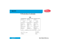
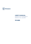
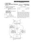
Table of contents
Preface . . . . . . . . . . . . . . . . . . . . . . . . . . . . . . . . . . . . . . . . . . . . . . 6
Safety instructions . . . . . . . . . . . . . . . . . . . . . . . . . . . . . . . . . . . . 9
Mercury Overview . . . . . . . . . . . . . . . . . . . . . . . . . . . . . . . . . . . . 13
The Mercury front. . . . . . . . . . . . . . . . . . . . . . . . . . . . . . . . . . . . . . . . . . . . 16
Keyboard of the Mercury . . . . . . . . . . . . . . . . . . . . . . . . . . . . . . . . . . . . . . 17
Display of Mercury . . . . . . . . . . . . . . . . . . . . . . . . . . . . . . . . . . . . . . . . . . . 18
The rear side of the Mercury . . . . . . . . . . . . . . . . . . . . . . . . . . . . . . . . . . . 21
Magazine and drive numbering. . . . . . . . . . . . . . . . . . . . . . . . . . . . . . . . . 22
Operating . . . . . . . . . . . . . . . . . . . . . . . . . . . . . . . . . . . . . . . . . . . 23
page 1
User Manual Mercury
Table of contents
Power on . . . . . . . . . . . . . . . . . . . . . . . . . . . . . . . . . . . . . . . . . . . . . . . . . . . 24
CD change in „locked“ mode . . . . . . . . . . . . . . . . . . . . . . . . . . . . . . . . . . 26
CD change via host computer. . . . . . . . . . . . . . . . . . . . . . . . . . . . . . . . . . 27
CD change via keyboard. . . . . . . . . . . . . . . . . . . . . . . . . . . . . . . . . . . . . . 29
Problems. . . . . . . . . . . . . . . . . . . . . . . . . . . . . . . . . . . . . . . . . . . . . . . . . . 31
CD and magazine change in „unlocked“ position . . . . . . . . . . . . . . . . . 32
CD change via keyboard and mailslot . . . . . . . . . . . . . . . . . . . . . . . . . . . 32
Survey of magazine change . . . . . . . . . . . . . . . . . . . . . . . . . . . . . . . . . . . 36
Setup . . . . . . . . . . . . . . . . . . . . . . . . . . . . . . . . . . . . . . . . . . . . . . . 44
Delivery . . . . . . . . . . . . . . . . . . . . . . . . . . . . . . . . . . . . . . . . . . . . . . . . . . . . 45
Placing the jukebox . . . . . . . . . . . . . . . . . . . . . . . . . . . . . . . . . . . . . . . . . . 47
Removing the transportation fixtures . . . . . . . . . . . . . . . . . . . . . . . . . . . 48
page 2
User Manual Mercury
Table of contents
Manually unlocking the door . . . . . . . . . . . . . . . . . . . . . . . . . . . . . . . . . . . 49
Removing the transportation fixtures . . . . . . . . . . . . . . . . . . . . . . . . . . . . 49
Connecting a host computer. . . . . . . . . . . . . . . . . . . . . . . . . . . . . . . . . . . 50
Connecting the serial interface (RS 232) for the robotic . . . . . . . . . . . . . . 50
Connecting the SCSI interface . . . . . . . . . . . . . . . . . . . . . . . . . . . . . . . . . 52
Setting the SCSI ID´s . . . . . . . . . . . . . . . . . . . . . . . . . . . . . . . . . . . . . . . . 57
Connecting to mains . . . . . . . . . . . . . . . . . . . . . . . . . . . . . . . . . . . . . . . . . 58
Chaniging the line voltage. . . . . . . . . . . . . . . . . . . . . . . . . . . . . . . . . . . . . 58
Connecting to mains . . . . . . . . . . . . . . . . . . . . . . . . . . . . . . . . . . . . . . . . . 59
Power on. . . . . . . . . . . . . . . . . . . . . . . . . . . . . . . . . . . . . . . . . . . . . . . . . . 59
Settings via the operator panel. . . . . . . . . . . . . . . . . . . . . . . . . . . . . . . . . 60
Clear Loader Status . . . . . . . . . . . . . . . . . . . . . . . . . . . . . . . . . . . . . . . . . 62
Setting the RS 232 ID for the robotic . . . . . . . . . . . . . . . . . . . . . . . . . . . . 62
page 3
User Manual Mercury
Table of contents
Setting the SCSI ID for the robotic . . . . . . . . . . . . . . . . . . . . . . . . . . . . . . 64
Disturbances. . . . . . . . . . . . . . . . . . . . . . . . . . . . . . . . . . . . . . . . . 67
Avoiding disturbances. . . . . . . . . . . . . . . . . . . . . . . . . . . . . . . . . . . . . . . . 67
Reports on the display. . . . . . . . . . . . . . . . . . . . . . . . . . . . . . . . . . . . . . . . 69
Setting Mercury to the initial state . . . . . . . . . . . . . . . . . . . . . . . . . . . . . . 71
Replacing line fuses. . . . . . . . . . . . . . . . . . . . . . . . . . . . . . . . . . . . . . . . . . 76
Appendix . . . . . . . . . . . . . . . . . . . . . . . . . . . . . . . . . . . . . . . . . . . . 77
Technical Data . . . . . . . . . . . . . . . . . . . . . . . . . . . . . . . . . . . . . . . . . . . . . . 77
Service. . . . . . . . . . . . . . . . . . . . . . . . . . . . . . . . . . . . . . . . . . . . . . . . . . . . . 81
Declaration of conformity . . . . . . . . . . . . . . . . . . . . . . . . . . . . . . . . . . . . . 82
page 4
User Manual Mercury
Table of contents
Index . . . . . . . . . . . . . . . . . . . . . . . . . . . . . . . . . . . . . . . . . . . . . . . 83
page 5
User Manual Mercury
1
Preface
1 Preface
This Product is a Laser Class 1 device. Disk access is carried out by using
a laser beam. The laser does not represent any risk for the user.
This product complies with the DHHS Rules 21CFR chapter 1, subchapter
J, applicable at the date of manufacturing. Accession number: 9520184
Conventions for this handbook:
D I S C GmbH is the manufacturer of the CD-ROM-jukebox
Mercury abbreviated DISC in this manual.
• As CD-ROM Compact Disk Read Only Media corresponding
to the following standards may be used:
- Red book, Yellow book
- CD-ROM XA
- Photo CD
- CD Bridge
- CD-I, CD-I Ready
page 6
User Manual Mercury
1
Preface
In the user’s manual each of these media are referred to as CD.
• Inside the jukebox CDs are transported only laying on a tray. The
trays with inserted CDs are stored in CD-magazines and are moved
on request between magazine and corresponding drive or the CDmailslot.
• Importing or exporting of CDs via the mailslot is called change of CDs
in the following text.
• In the following the identification number or unit addresses are abbreviated ID numbers (or ID).
page 7
User Manual Mercury
1
Preface
Edition 0801
Copyright:
DISC GmbH - 55411 Bingen am Rhein - Germany
All rights reserved. No part of this manual may be reproduced, or transmitted, in any form or by any means, electronic, mechanical, photocopying,
recording, or otherwise without the prior permission of DISC GmbH.
Any changes based on the expected technical progress are subject to be
made without notice.
page 8
User Manual Mercury
2
Safety instructions
2 Safety instructions
Intended use
The Mercury jukebox is exclusively determined to access and write CD´s,
controlled by a host computer.
Any other usage apart from this is regarded as not intended.
The technology of the DISC Mercury jukebox corresponds to the state of
the art and is very reliable when operating.
Improper use of the Mercury jukebox may cause residual risks if it is operated or used by non-authorized persons. Any person who is engaged to
operate the jukebox Mercury has to read and understand this user’s manual, especially these safety instructions.
Residual risks
In this user’s manual residual risks are marked as follows:
Warning
Disregarding the safety message following „Warning“ can cause material
damage (damage of parts).
page 9
User Manual Mercury
2
Safety instructions
Danger
Disregarding the safety messages following „Danger“ can cause personal
damage.
Ban of arbitrary
reversions and
changes
The jukebox Mercury must not be changed in construction or concerning
safety regulations. Any change will lead to the exclusion of liability of
DISC GmbH concerning the resulting damages. Especially defective
parts must be replaced only by original spare parts of DISC.
Repair
Repair must be carried out only by the D service staff, or by qualified
and authorized service staff.
page 10
User Manual Mercury
2
Safety instructions
Warning:
Setup:
Before you connect this unit to the mains, please check your mains voltage
and compare if with the setting of the unit. If your mains voltage does not
correspond to the mains voltage setting of the unit, please change the setting according to the instruction in this manual. Replace fuses only with
same types and values!
Self-adhesive labels on the CD´s:
Do not use self-adhesive labels for the lettering your CD´s. This labels may
loosen itself and then cause damages of the drives and the CD´s.
Fire damages:
To reduce fire or shock hazard, do not expose this appliance to rain or
moisture.
Opening device:.
To prevent electrical shock, remove power line before opening this appliance!
page 11
User Manual Mercury
2
Safety instructions
Danger:
Disassembling parts and changing of any adjustments, apart from those
specified within this manual, may result in exposure to hazardous laser
radiation.
Security for data
Access to the CD magazines is possible only with opening the door of the
jukebox. This can be done with the original key or through the superior
host computer. Access to CD´s via mailslot is only possible by key or by
CD-release through the superior host computer. You have the responsibility to allow access to the stored data only to authorized persons. I. e. only
the system administrator is instructed to handle the key and thus to have
access to the data.
Electro Magnetic
Compatibility
For the CE certification, the Mercury jukebox was tested with Adaptec
2940 and 3940 SCSI host adapters. Using any other type of SCSI host
adapter, the Mercury might be out of range regarding the electro magnetic
emission, especially when the Jukebox is equipped with DVD drives.
page 12
User Manual Mercury
3
Mercury Overview
3 Mercury Overview
The Mercury is a CD-ROM jukebox with 3 magazines (carrying 50 CD´s
each).
Depending on the type of the unit you will get different configurations of CD
drives and interfaces.
SCSI drive
page 13
SCSI bus A S CSI bus B Position in
jukebox
CD ROM drive 1
X
1
CD ROM drive 2
X
2
CD ROM drive 3
X
3
CD ROM drive 4
X
4
CD-R drive 1
X
1
CD-R drive 2
X
2
User Manual Mercury
3
Mercury Overview
SCSI drive
SCSI bus A S CSI bus B Position in
jukebox
DVD drive 1
X
1
DVD drive 2
X
2
DVD drive 3
X
3
DVD drive 4
X
4
SCSI robotic controller
X
For models with CD-R and DVD drives, the CD-R drives are always
mounted to position 1 (and 2) inside the jukebox.
For Mercury models with 4 CD ROM drives, SCSI bus B is not equipped.
Models with SCSI controlled robotic have a serial service interface. This
service interface can not be used to operate the jukebox with a standard
host application.
page 14
User Manual Mercury
3
Mercury Overview
Models with a Differential Ended SCSI interface can only be connected to
a Differential Ended SCSI host adapter. Connecting a Differential Ended
SCSI interface to a Single Ended SCSI host adapter can cause demage to
the jukebox and the SCSI host adapter.
The magazines can be exchanged without much difficulty. The change of
CD´s is comfortably made with the CD-mailslot at the front of the unit.
The basic functions are controlled manually via the keyboard panel and
the LCD-display (off-line without control of the host computer).
Access to the CD´s and the CD magazines is secured with a key-operated
lock.
page 15
User Manual Mercury
3
Mercury Overview
3.1 The Mercury front
(1) LED display: Status of the drives (D1-D4)
(2) LCD display: Dialog display for manual operation and for information about the mode of operation of the jukebox
(3) Keyboard
(4) CD mailslot for removal and insertion of single CD´s;
(5) Key: Open door
(6) Key-operated safety lock
(7) Emergency door open
(8) Power-on switch
page 16
User Manual Mercury
3
Mercury Overview
3.2 Keyboard of the Mercury
With the keyboard you may enter preoperational commands or commands
and data while operating the unit.
Key
Key
Key
page 17
to confirm input
to cancel input
to change CD’s via the mailslot or to activate service
functions
User Manual Mercury
3
Mercury Overview
3.3 Display of Mercury
The LCD-display and the LEDs will give you information about the actual
status of the unit.
LCD-display Basic
The LCD-display indicates in the basic state which CD´s are placed in the
single drives.
D1: -.-D3: -.--
D2: -.-D4: -.--
The detailed meaning of the displayed information:
Dn:m.s
Dn =
Number of the drive (D1-D4)
m
=
Number of the CD-magazine (1-3)
ps =
Position number of the CD (01-50)
page 18
User Manual Mercury
3
Mercury Overview
Example (Mercury 40):
MS: 1.27 D1: 2.03
D2: -.-D3: -.-This example means:
CD number 27 of CD magazine 1 is placed in the mailslot (MS).
CD number 03 of magazine 2 is placed in drive 1.
No CD´s in drive 2 and 3.
The status of drive 4 is not displayed because the status of the mailslot is
displayed.
LCD-display Text
Informations about status and system messages.
LED display
The 4 LED´s (D1-D4) will show the status of the drives.
page 19
User Manual Mercury
3
Mercury Overview
off
short time out
on
Note:
page 20
No CD-tray in drive.
Drive is loaded.
Drive is ready to play.
The messages shown above are always displayed when a CD-tray is
loaded into a drive even if there is no CD within the tray.
User Manual Mercury
3
Mercury Overview
3.4 The rear side of the Mercury
(1)
(2)
(3)
(4)
(5)
(6)
(7)
page 21
Type plate
SCSI bus A
SCSI bus B
Switches for SCSI ID´s of drives
Serial interface
Fuses and voltage selector
Socket for connecting the line voltage
User Manual Mercury
3
Mercury Overview
3.5 Magazine and drive numbering
page 22
User Manual Mercury
4
Operating
4 Operating
The Mercury has two operating levels depending on the position of the key
operated safety lock in order to change CD´s.
Lock secured
In the „locked“ position the entire control is performed by the host computer. A change of CD´s is possible only by using the mailslot function if
the host computer has initiated this change.
Lock open
In the position „unlocked“ the Mercury will not execute any command of the
host computer except status request:
• Changing single CD´s via mailslot is possible.
• Opening the doors and changing CD magazines or CD´s is possible.
page 23
User Manual Mercury
4
Operating
4.1 Power on
Note
Always power-on the jukebox before you power on your host computer. Otherwise it is possible that the host computer will not recognize the jukebox.
Action
Display / status
Turn the line switch „Power“ to posi- Mercury shortly displays type and
tion „I“
date of the firmware for 2 sec.
Mercury-40
V0306
18/06/97
page 24
User Manual Mercury
4
Operating
Action
Display / status
Mercury displays the status.
D1: -.-D3: -.--
D2: -.-D4: -.--
Mercury is ready.
page 25
User Manual Mercury
4
Operating
4.2 CD change in „locked“ mode
In the position „locked“ of the safety lock you can change CD´s via the
mailslot.
The CD to be changed is selected or released by the host computer.
Note:
1) Always put CD´s with label up on a tray.
2) Never insert the CD into the mailslot without a tray.
Otherwise serious faults may occur in the Mercury.
page 26
User Manual Mercury
4
Operating
4.2.1 CD change via host computer
At your request the host computer selects the CD to be changed and starts
the change process.
CD change via
host computer
Action
Display / status
Request a CD to be changed (at the Mercury opens the mailslot which
host computer).
carries the requested CD.
Mercury shows the origin of this CD
(magazine No. 1; CD No. 27).
MS: 1.27 D1: 2.03
D2: -.-D3: -.--
page 27
User Manual Mercury
4
Operating
Action
Display / status
Mercury opens the mailslot.
Export done
Take the CD out of the mailslot.
Insert new CD.
Confirm this new CD.
Depending on the control software
this confirming is done
- by pressing „ENTER“ at Mercury
- at the host computer.
Mercury closes the mailslot.
D1: 2.03
D2: -.--
D2: -.-D3: -.--
The CD change is finished.
page 28
User Manual Mercury
4
Operating
4.2.2 CD change via keyboard
To change a CD in this mode you enter magazine and CD number via keyboard. The CD has to be released by the host computer.
Confirm entries by pressing key „ENTER“ or cancel action with key „ESC“.
Action
Display / status
Press key „F“.
Export element
MS: ?.-Enter magazine number and CD
number, press key „ENTER“.
page 29
Export element
MS: 1.27 Start?
User Manual Mercury
4
Operating
Action
Display / status
Mailslot is opened.
Export done
Take CD out of mailslot.
Insert new CD.
Press key „ENTER“.
The mailslot is closed and Mercury
will lay back the CD.
D1: 2.03
D2: -.--
D2: -.-D3: -.--
The CD change is finished.
page 30
User Manual Mercury
4
Operating
4.2.3 Problems
Problems?
page 31
Problem
Reason / remedy
There is no tray in the mailslot.
Mercury has accessed a magazine
number without CD-tray.
Always insert a new CD only in a
CD-tray.
On no account you should insert a
CD if there is no tray in the mailslot.
There is no CD on the tray.
Mercury has accessed a magazine
number without CD.
User Manual Mercury
4
Operating
4.3 CD and magazine change in „unlocked“ position
CD change When is it possible to change?
The CD´s are secured against unauthorized access with a safety lock.
The host computer normally serves a data base concerning the inserted
CD´s of the Mercury.
If you change a CD or a magazine you must take care that the host’s data
base is updated.
4.3.1 CD change via keyboard and mailslot
To change a CD in this mode you enter magazine and CD number via keyboard. Confirm entries by pressing the key „ENTER“ or cancel with key
„ESC“.
page 32
User Manual Mercury
4
Operating
CD change via
keyboard
Action
Display / status
Turn key in position „unlocked“.
Unlocked
Press key „F“.
Export element
MS: ?.-Enter magazine number and CD
number, press key „ENTER“.
page 33
Export element
MS: 1.27 Start?
User Manual Mercury
4
Operating
Action
Display / status
Mailslot will be opened.
Export done
Take CD out of mailslot.
Insert new CD.
Press key „ENTER“.
Mercury will lay back the CD.
Unlocked
page 34
User Manual Mercury
4
Operating
Action
Display / status
To change more CD´s:
Again press key „F“.
Turn the key back to position
„locked“.
page 35
The CD change is finished.
User Manual Mercury
4
Operating
4.3.2 Survey of magazine change
Changing magazines or CD´s within magazines should be performed as
follows:
• Turn key into position „unlocked“; open the door
• Take out magazine
• Insert CD´s
• Re-insert magazine
• Close the door; turn the key into position „locked“
For details see next pages.
page 36
User Manual Mercury
4
Operating
Warning:
When the door is open you have access to the Inside of the unit.
You must not handle inside the unit using any tools.
There is the risk that in doing so components are being damaged.
The door of the Mercury is secured by a lock. Access to the CD´s is only
possible if this safety lock is in position „unlocked“.
Action
Turn the key into position „unlocked“
(1).
page 37
Display / status
Unlocked
User Manual Mercury
4
Operating
Action
Press buton „Open Door“ (2) for 3
sec.
Display / status
Hold Button
Unloaded
Please Wait ....
Mercury opens the door.
Door is open
Now you may take out the magazines.
page 38
User Manual Mercury
4
Operating
Fold out the handle of the magazine
Release the magazine
page 39
User Manual Mercury
4
Operating
Take out the magazine
page 40
User Manual Mercury
4
Operating
Exchanging CD´s
• Pull out CD-tray half the way.
• Insert CD face up into the CD-tray.
• Push in CD-tray.
• Repeat these steps for further CD´s.
page 41
User Manual Mercury
4
Operating
Insert magazine
• Insert the magazine.
• The magazine must snap in clearly audible.
• The locking lever must be in the position „locked“.
Note:
Observe the sticker „TOP/OBEN“ on the CD magazine.
page 42
User Manual Mercury
4
Operating
Close the door;
turn the key into
position „locked“
Action
Display / status
Door is open
Close the door.
Note:
First close the backside door.
Turn the key into position „locked“.
Unlocked
Mercury performs a RESET.
D1: -.-D3: -.--
D2: -.-D4: -.--
Mercury is ready.
page 43
User Manual Mercury
5
Setup
5 Setup
In this chapter you will find all information necessary to activate the Mercury jukebox.
Warning:
Bevor connecting to mains:
1. Check the voltage setting.
2. Remove the transportation fixtures inside the jukebox.
Seite 44
User Manual Mercury
5
Setup
5.1 Delivery
Note:
Store the packaging of the jukebox for a possible later transport.
Thus you can ship the jukebox safely.
Mercury
RS 232
Mercury
SCSI
Mercury
SCSI Diff.
Power cord
3
3
3
RS 232 cable
1
--
--
1 per SCSI bus
1 per SCSI bus
--
Differential Terminator
--
--
1 per SCSI bus
Fuses
3
3
3
Keys
2
2
2
Single Ended Terminator
Seite 45
User Manual Mercury
5
Setup
Mercury
RS 232
Mercury
SCSI
Mercury
SCSI Diff.
Emergency pin
1
1
1
Quick Installation Guide
1
1
1
User Manual CD
1
1
1
Unit Mercury
1
1
1
Please check if the delivery is complete.
Seite 46
User Manual Mercury
5
Setup
5.2 Placing the jukebox
The Mercury jukebox is intended to be used in offices.
Note:
After delivery the temperature of the jukebox should be adapted
slowly to the room temperature.
Avoid places with:
• extreme temperatures or excessive sun exposure
• high humidity
• contact with water and chemicals
• extreme vibrations
Seite 47
User Manual Mercury
5
Setup
The right location:
• has a stable, even support
• sufficient space to pull out the unit
5.3 Removing the transportation fixtures
Warning:
The unit must be switched on only when the tranbsportation fixtures have been removed.
Note:
Store the transportation fixtures in a safe place. Insert them always
to the jukebox before transporting the unit.
Seite 48
User Manual Mercury
5
Setup
5.3.1 Manually unlocking the door
To remove the transportation fixtures from the inside of the unit, open the
doors with the emergency pin.
1)
2)
Turn the key to position „unlocked“.
Insert the emergency pin into the aperture beside the key and press
in as deep as necessary to get the door open.
5.3.2 Removing the transportation fixtures
1) Remove the transportation fixture above magazine 3.
2) Remove the transportation fixture between the magazines.
3) Take ou the magazines and remove the two red transportation fixtures which fix the trays.
4) Return the magazines.
5) Close the doors.
6) Set the key to „locked“.
Seite 49
User Manual Mercury
5
Setup
5.4 Connecting a host computer
5.4.1 Connecting the serial interface (RS 232) for the robotic
Warning:
Switch off the Mercury and the host computer when connecting the
cable, otherwise the interfaces might be damaged.
Description
The Mercury can have a serial interface (RS 232) for robotics control or
optional a SCSI robotics interface.
Models with serial robotics control have two RS 232 interfaces (in and out),
models with SCSI robotics control have only one serial service interface
which can not be used for normal jukebox control.
Further jukeboxes
If necessary further jukeboxes can be cascaded to the RS 232 out interface. The complete lenght of the serial bus should not be more than 15 m.
Do not connect more than 3 units to one serial bus. Each unit has aunique
RS 232 ID which can be set with the operator panel (see 5.6.2).
Seite 50
User Manual Mercury
5
Setup
1) Host computer
2) Connection host computer to RS 232 interface
3) Connection to next
jukebox on the serial
bus (6)
Seite 51
User Manual Mercury
5
Setup
5.4.2 Connecting the SCSI interface
Warning:
SCSI robotics
control
Switch off the jukebox and the host computer before connecting
the SCSI interface, otherwise the interfaces might be damaged.
Units with SCSI robotics control requiere an extra SCSI ID for the robotic
on the SCSI bus. The SCSI ID for the robotic can be set / changed via the
operator panel (see chapter 5.6.3). For units with 2 SCSI busses, the
robotic interface is always connected to SCSI bus A.
Differential
Ended SCSI
Warning:
Do not connect Differential Ended SCSI devices to Single Ended
SCSI host adapters. The device and the host adapter will be damaged.
Units equipped with Differential Ended SCSI interface have a note on the
Seite 52
User Manual Mercury
5
Setup
backplane next to the SCSI interface. For terminating Differential Ended
SCSI busses do only use Differential Ended SCSI terminators.
SCSI cable
Use only high quality SCSI cables. For the maximum cable lenght of the
SCSI bus see table below.
Data Mode
Single Ended
Differential
Asynchronous mode (5 MB/s)
6m
25 m
Synchronous mode (5 MB/s)
6m
25 m
Synchronous mode Fast (10 MB/s)
3m
12 m
1,5 m
6m
Ultra SCSI mode (20 MB/s)
The lenght of the SCSI cable inside the jukebox is 60 cm.
Seite 53
User Manual Mercury
5
Setup
Units with one
SCSI bus
1) Host computer
2) Connection host computer to SCSI A2
3) Connection additional SCSI devices to
SCSI A1
If the jukebox is the last device on the SCSI bus,
the SCSI bus has to be terminated with an
external SCSI terminator.
Seite 54
User Manual Mercury
5
Setup
Units with two
SCSI busses
Jukeboxes, which are equipped with CD-R or DVD drives have two SCSI
busses. For a table with the drive assignment see chapter 3.
Connecting the jukebox to 2 SCSI host adapters
1)
2)
3)
4)
5)
Host computer
Connection to additional SCSI device or
external SCSI terminator to SCSI A1
Connection host computer to SCSI A2
Connection to additional SCSI device or
external SCSI terminator to SCSI B3
Connection host computer to SCSI B4
If during the writing process of CD-R media the
CD-ROM or DVD drives should be accessible for
other users, it is recommended to connect the
recorder(s) to an extra SCSI bus.
Seite 55
User Manual Mercury
5
Setup
Connecting units with 2 SCSI busses to 1 SCSI host adapter
To connect all drives of units with 2 SCSI busses to 1 SCSI host adapter,
the SCSI busses of the jukebox can be daisy chained.
1) Host computer
2) Connection to additional SCSI device or
external SCSI terminator to SCSI A1
3) Connection SCSI B3 to SCSI A2
4) Connection host computer to SCSI B4
Seite 56
User Manual Mercury
5
Setup
5.4.3 Setting the SCSI ID´s
The SCSI ID´s of the CD ROM, CD-R and DVD drives can be changed
with the ID switches at the rear of the jukebox.
For models with SCSI robotic control it might be necessary to change the
SCSI ID for the robotic.For information how to change the SCSI ID for the
robotic see chapter 5.6.3.
The ID range for the drives and the robotic is 0 to 6. For CD-R devices it is
recommended to use SCSI ID 6 (and 5) because of the higher priority of
these ID´s on the SCSI bus.
Seite 57
User Manual Mercury
5
Setup
5.5 Connecting to mains
5.5.1 Chaniging the line voltage (old power supply unit only)
Warning:
Befor connection the jukebox to line voltage, check if the voltage
setting fits to the line voltage of your country. If not change the
voltage setting.
Unplug the power cord before changing the voltage setting.
• Open drawer extra safe with a suitable screw driver and pull out. Take
care that the fuses do not fall out..
• Pull out the grey insert (voltage selector) for voltage setting.
• Turn voltage selector and insert in such way that the desired voltage
is visible in the small window.
• Push in again the insert.
Seite 58
User Manual Mercury
5
Setup
5.5.2 Connecting to mains
With the Mercury a power cord corresponding to your common wall outlet
is delivered. Use this power cord to connect the jukebox to mains.
5.5.3 Power on
After finishing the setup, the jukebox can be switched on. After powerin up
the jukebox the display shows the firmware revision level of the jukebox for
a few seconds and then goes to the status display of the drives.
Mercury-40
V0308 18/06/97
D1: -.- - D2: -.- D3: -.- - D4: -.- -
Seite 59
User Manual Mercury
5
Setup
5.6 Settings via the operator panel
The Mercury offers a special mode (Power-on menu) in which several
parameters of the jukebox can be set and edited.
Aktivating the
Power-on menu
To activate the Power-on menu press the keys ‘F‘ + ´1´ + ´Enter‘ at the
same time. Alternately the Power-on menu can be activated by switching
off the jukebox and holding the ´F´ key while the jukebox is powerd on
again. The Power-on menu can only be activated while the jukebox is in
„unlocked“ mode.
Leaving the
Power-on menu
After finishing and storing the settings with ‘Enter‘, press ‘Esc‘ to leave the
Power-on menu. The jukebox returns to normal operation mode.
Note:
Seite 60
During the Mercury is set to the Power-on meu, the RS 232 interface
is not available.
User Manual Mercury
5
Setup
Warning:
In the Power-on menu, the Mercury offers several functions to
adjust the settings for the lift and for the pickers. These functions
should only be used by authorized service providers. Changing the
settings for the lift or the pickers by accident can cause serious
problems.
If you active one of those service functions by accident, leave this
function emediatly by pressing the ‘ESC‘ key.
Functions of the
Power-on menu
Key
Seite 61
Function
Description
0
Clear Loader Status
Deletes all status information
1
Picker Reference
For service only
2
Lift Reference
For service only
3
RS 232 ID
Setting the RS 232 ID for the robotic
4
SCSI ID Robotic
Setting the SCSI ID for the robotic
User Manual Mercury
5
Setup
Key
Function
Description
5
Lift Adjustment
For service only
6
CDC 150 Demo
Demolrun for jukebox robotic
7
Quick Test
For service only
8
Self Test
For service only
9
Bootloader
Bootloader for firmware updates
5.6.1 Clear Loader Status
For information about the Clear Loader Status function see chapter 6.3.
5.6.2 Setting the RS 232 ID for the robotic
The factory default setting for the RS 232 ID is 00. The ID range for the RS
232 ID is 00 to 15.
Seite 62
User Manual Mercury
5
Setup
Changing the RS 232 ID is only necessary if more than 1 jukebox should
be connected to the same serial bus.
Note:
For units with SCSI controlled robotic, the RS 232 ID has to be set
to ID 0. This setting must not be changed.
Activity
Display / status
Aktivate thePower-on menu
Press
Use
and
232 ID
Seite 63
Power-on menu
Function?
Set RS232-ID to:
00
to select the RS
Set RS232-ID to:
02
User Manual Mercury
5
Setup
Activity
Display / status
Confirm selection with
RS232-ID set to
02
Power-on menu
Function?
Press
and set key to „locked“
D1:_ . _ _ D2:_ . _ _
D3:_ . _ _ D4:_ . _ _
5.6.3 Setting the SCSI ID for the robotic
The factory default setting for the robotic SCSI ID is 6. To avoid ID conflicts
with other SCSI devices, the SCSI ID for the robotic can be changed. The
range for the SCSI robotic ID is 0 to 7.
Seite 64
User Manual Mercury
5
Setup
Note:
Normally SCSI ID 7 is assigned to the SCSI host adapter.
Activity
Aktivate the Power-on menu
Press
Seite 65
Display / status
Power-on menu
Function?
The ID setting for the drives is displayed.
Set SCSI-ID of
Drive 1 to 3
User Manual Mercury
5
Setup
Activity
Display / status
Press
4 times to select the setting for the robotic SCSI ID
Use
and
to select the ID
Confirm with
Set SCSI-ID of
Controller to _ _
Set SCSI-ID of
Controller to 02
SCSI IDs set
Power-on menu
Function?
Press
Seite 66
and set key to „unlocked“
D1:_ . _ _ D2:_ . _ _
D3:_ . _ _ D4:_ . _ _
User Manual Mercury
6
Disturbances
6 Disturbances
6.1 Avoiding disturbances
Reason of
disturbances
Mechanical disturbances mostly are caused by:
• Errors during the loading process of the magazines
• A wrong manual change of the CDs
• Self-adhesive labels for the lettering the CDs
To avoid disturbances please adhere to the following recommendations:
page 67
User Manual Mercury
6
Disturbances
No self-adhesive
labels
Do not use self-adhesive labels for the lettering your CDs. This labels may
loosen itself and then cause damages of the drives and the CDs.
Use CD-tray
Put CDs only into the mailslot laying on CD-trays. CDs can only be transported if they are placed on trays.
If you insert a CD without tray this will lead to mechanical disturbances.
Load CD magazines completely
Load the CD magazines completely with trays even if you do not fill in all
trays with CDs.
Operate the Mercury only with all 150 trays installed. By factory setting all
magazines are equipped with all trays. Do not remove trays.
Insert CD magazines correctly
When inserting CD magazines pay attention to the TOP position. The
magazines must snap in clearly audible. An incorrectly inserted CD magazine will lead to mechanical disturbances.
page 68
User Manual Mercury
6
Disturbances
6.2 Reports on the display
In the table some display reports are listed. The given information is
intended to help you to remove disturbances.
Report
Reason
Accomodation
Door is open
The doors of Mercury are open.
CD magazines can be exchanged.
If you want a normal operating
mode:
Close the doors manually.
unlocked
The key of the safety lock is in posi- Turn key to position „locked“.
tion „unlocked“. Mercury cannot perform any command (e.g. CD
change) from the host computer
except status request.
In this position of the key the doors
can be opened and there is access
to the power-on menu.
page 69
User Manual Mercury
6
Disturbances
Report
Reason
Unloading
Please Wait
Mercury removes all CDs from the None, wait until the process is termidrives and the mailslot and puts
nated.
them back into the respective magazines. This process is performed
always before it is possible to open
the door.
locked
Message in power-on menu. Entries Turn key to position „unlocked“ if
are not possible.
necessary.
Access denied
Safety lock in position „locked“.
You have tried to make input which
are admissible only in the position
„unlocked“.
page 70
Accomodation
Turn key to position „unlocked“.
User Manual Mercury
6
Disturbances
6.3 Setting Mercury to the initial state
When required?
page 71
Depending on incorrect change of magazines or CDs by the operator or by
Mercury the internally stored informations do not longer correspond to the
actual positions of CDs.
User Manual Mercury
6
Disturbances
Status of the
Mercury
The unit does not react correctly.
Steps:
Actions:
Step 1:
Take out all magazines
and trays of Mercury.
Power-on the unit at the „Power-on“ switch.
Turn key to position „unlocked“.
Open the door:
Press key „Open Door“ and wait until door will open.
Power-off the unit.
Take out all magazines (see page 3-6).
Note:
Do not remove trays
from the lift.
page 72
Take out all trays of the drives and the mailslot.
User Manual Mercury
6
Disturbances
Steps:
Actions:
Step 2:
Clear „loader status“.
Press key „F“ and hold on until menu Mercury enters power-on menu.
is displayed;
switch on the unit
Power-on-menu:
Function?
Danger:
Do not handle inside the
open Mercury while
clearing the „loader status“. In this mode the
lift can move up/down
and there is a risk of
injury for your hands.
page 73
User Manual Mercury
6
Disturbances
Steps:
Actions:
Select „Clear loader status“ by
pressing key „0“.
Confirm clearing by pressing key
„ENTER“.
Clear loader
status?
Status is cleared.
Press key „ESC“.
Step 3:
Remove tray from
mailslot.
page 74
If there was a tray left in the lift it is automatically placed in the mailslot.
Remove the tray from the mailslot (see page 3-2).
User Manual Mercury
6
Disturbances
Steps:
Actions:
Step 4:
Insert magazines.
Correctly place all trays with CDs into the magazines and insert the magazines into the Mercury.
Close the door.
Turn key to position „locked“.
Mercury is ready.
D1: -.-D3: -.--
page 75
D2: -.-D4: -.--
User Manual Mercury
6
Disturbances
6.4 Replacing line fuses (old power supply unit only)
Danger:
Unplug the power cord before exchanging line fuses.
Use only fuses as specified below.
Note:
The two line fuses have the value T 2,5 A; 250 V for all line voltages
(100/120/230 V).
• Open drawer extra safe (1) using a suitable screw driver and pull out.
Take care that the fuses do not fall out.
• Don’t pull out the grey voltage selector (2). The line voltage must not
be changed!
• Replace always both fuses.
• Re-insert the drawer extra safe (1).
page 76
User Manual Mercury
7
Appendix
7 Appendix
7.1 Technical Data
Interfaces
RS 232 interface
SCSI-2 interface
page 77
RS 232 ID
0
Baud rate
9600 Baud
Startbits
1
Stopbits
1
Databits
8
Parity
none
ID range
ID 0 - 15
SCSI ID (robotic)
2
ID range
ID 0 - 7
User Manual Mercury
7
Appendix
Operating conditions
Ambient temperature
operating
10oC - 33oC
50oF - 91,4oF
Gradient of temperature
11oC/h
19,8oF/h
Relative humidity
operating
10% - 75%
non condensing
Power supply
page 78
Line voltage
90 V - 240 V / 2 A
Frequency range
50 / 60 Hz
Power consumption normal
40 W - 65 W
Power consumption max.
85 W - 130 W
User Manual Mercury
7
Appendix
Dimensions and weight
Dimenions
Weight without CD´s
Width
218 mm
Hight
519 mm
Depth
600 mm
2 drives
28,6 kg
4 drives
30,2 kg
Robotic
Media load time min: 1 sec.
page 79
Media load time
max:
2,5 sec.
Media swap time
4 sec. (average)
User Manual Mercury
7
Appendix
Robotic
MSBF (mean swaps 2.500.000
between failure)
cycles
Drives
DVD - ROM
Tosbiba SD-M1401
CD-R
Plextor 12/10/32 S
Supported formats:
Red book, Yellow book, CD-ROM XA,Photo CD , CD Bridge, CD-I, CD-I
Ready; packet writing. Please take care your CD-R media suport 12X writing.
page 80
User Manual Mercury
7
Appendix
7.2 Service
Necessary service is supported by your distributor.
Hot-Line:
page 81
International:
Germany:
USA:
+49 6721 964 222
0 6721 964 222
+1 631 273 4600 extension 107 or 108
Internet:
http://www.nsmstorage.com
User Manual Mercury
7
Appendix
7.3 Declaration of conformity
page 82
User Manual Mercury
Index
8 Index
B
Ban of arbitrary reversions and changes . . . . . . . . . . . . . . . . . . . . . . 10
Bootloader . . . . . . . . . . . . . . . . . . . . . . . . . . . . . . . . . . . . . . . . . . . . . 62
C
CD change . . . . . . . . . . . . . . . . . . . . . . . . . . . . . . . . . . . . 26, 27, 29, 32
CD ROM drive . . . . . . . . . . . . . . . . . . . . . . . . . . . . . . . . . . . . . . . . . 13
CDC 150 Demo . . . . . . . . . . . . . . . . . . . . . . . . . . . . . . . . . . . . . . . . . 62
CD-R drive. . . . . . . . . . . . . . . . . . . . . . . . . . . . . . . . . . . . . . . . . . . . . 13
Clear Loader Status . . . . . . . . . . . . . . . . . . . . . . . . . . . . . . . . . . . 61, 62
Connecting a host computer . . . . . . . . . . . . . . . . . . . . . . . . . . . . . . . 50
Connecting the SCSI interface. . . . . . . . . . . . . . . . . . . . . . . . . . . . . . 52
Connecting to mains . . . . . . . . . . . . . . . . . . . . . . . . . . . . . . . . . . . . . 58
page 83
User Manual Mercury
Index
D
Differential Ended SCSI . . . . . . . . . . . . . . . . . . . . . . . . . . . . . . . . . . 15
Dimensions . . . . . . . . . . . . . . . . . . . . . . . . . . . . . . . . . . . . . . . . . . . . 79
Display . . . . . . . . . . . . . . . . . . . . . . . . . . . . . . . . . . . . . . . . . . . . . . . . 18
Disturbances . . . . . . . . . . . . . . . . . . . . . . . . . . . . . . . . . . . . . . . . . . . 67
Drives. . . . . . . . . . . . . . . . . . . . . . . . . . . . . . . . . . . . . . . . . . . . . . . . . 80
DVD drive . . . . . . . . . . . . . . . . . . . . . . . . . . . . . . . . . . . . . . . . . . . . . 14
E
Electro Magnetic Compatibility . . . . . . . . . . . . . . . . . . . . . . . . . . . . 12
Emergency door open . . . . . . . . . . . . . . . . . . . . . . . . . . . . . . . . . . . . 16
F
Fuses . . . . . . . . . . . . . . . . . . . . . . . . . . . . . . . . . . . . . . . . . . . 21, 45, 76
page 84
User Manual Mercury
Index
I
Intended use . . . . . . . . . . . . . . . . . . . . . . . . . . . . . . . . . . . . . . . . . . . . . 9
K
Keyboard . . . . . . . . . . . . . . . . . . . . . . . . . . . . . . . . . . . . . . . . . . . 16, 17
L
LCD display. . . . . . . . . . . . . . . . . . . . . . . . . . . . . . . . . . . . . . . . . . . . 16
LED display . . . . . . . . . . . . . . . . . . . . . . . . . . . . . . . . . . . . . . . . . . . . 16
Lift Adjustment . . . . . . . . . . . . . . . . . . . . . . . . . . . . . . . . . . . . . . . . . 62
Lift Reference . . . . . . . . . . . . . . . . . . . . . . . . . . . . . . . . . . . . . . . . . . 61
M
Magazine change . . . . . . . . . . . . . . . . . . . . . . . . . . . . . . . . . . . . . . . . 36
page 85
User Manual Mercury
Index
Mailslot . . . . . . . . . . . . . . . . . . . . . . . . . . . . . . . . . . . . . . . . . . . . . . . 16
Mercury Overview. . . . . . . . . . . . . . . . . . . . . . . . . . . . . . . . . . . . . . . 13
O
Operating conditions . . . . . . . . . . . . . . . . . . . . . . . . . . . . . . . . . . . . . 78
P
Picker Reference . . . . . . . . . . . . . . . . . . . . . . . . . . . . . . . . . . . . . . . . 61
Placing the jukebox . . . . . . . . . . . . . . . . . . . . . . . . . . . . . . . . . . . . . . 47
Power cord . . . . . . . . . . . . . . . . . . . . . . . . . . . . . . . . . . . . . . . . . . . . . 45
Power on . . . . . . . . . . . . . . . . . . . . . . . . . . . . . . . . . . . . . . . . . . . 24, 59
Power supply . . . . . . . . . . . . . . . . . . . . . . . . . . . . . . . . . . . . . . . . . . . 78
Power-on menu . . . . . . . . . . . . . . . . . . . . . . . . . . . . . . . . . . . . . . . . . 60
Power-on switch . . . . . . . . . . . . . . . . . . . . . . . . . . . . . . . . . . . . . . . . 16
Preface . . . . . . . . . . . . . . . . . . . . . . . . . . . . . . . . . . . . . . . . . . . . . . . . . 6
Problems . . . . . . . . . . . . . . . . . . . . . . . . . . . . . . . . . . . . . . . . . . . . . . 31
page 86
User Manual Mercury
Index
Q
Quick Test . . . . . . . . . . . . . . . . . . . . . . . . . . . . . . . . . . . . . . . . . . . . . 62
R
Repair. . . . . . . . . . . . . . . . . . . . . . . . . . . . . . . . . . . . . . . . . . . . . . . . . 10
Residual risks. . . . . . . . . . . . . . . . . . . . . . . . . . . . . . . . . . . . . . . . . . . . 9
Robotic. . . . . . . . . . . . . . . . . . . . . . . . . . . . . . . . . . . . . . . . . . . . . . . . 79
RS 232 cable . . . . . . . . . . . . . . . . . . . . . . . . . . . . . . . . . . . . . . . . . . . 45
RS 232 ID . . . . . . . . . . . . . . . . . . . . . . . . . . . . . . . . . . . . . . . . . . 61, 62
RS 232 interface . . . . . . . . . . . . . . . . . . . . . . . . . . . . . . . . . . . . . . . . 77
S
SCSI bus A . . . . . . . . . . . . . . . . . . . . . . . . . . . . . . . . . . . . . . . . . . . . 21
SCSI bus B. . . . . . . . . . . . . . . . . . . . . . . . . . . . . . . . . . . . . . . . . . . . . 21
SCSI cables . . . . . . . . . . . . . . . . . . . . . . . . . . . . . . . . . . . . . . . . . . . . 53
SCSI ID . . . . . . . . . . . . . . . . . . . . . . . . . . . . . . . . . . . . . . . . . . . . 61, 64
page 87
User Manual Mercury
Index
SCSI ID´s. . . . . . . . . . . . . . . . . . . . . . . . . . . . . . . . . . . . . . . . . . . . . . 57
SCSI robotic controller . . . . . . . . . . . . . . . . . . . . . . . . . . . . . . . . . . . 14
SCSI-2 interface. . . . . . . . . . . . . . . . . . . . . . . . . . . . . . . . . . . . . . . . . 77
Self Test . . . . . . . . . . . . . . . . . . . . . . . . . . . . . . . . . . . . . . . . . . . . . . . 62
Serial interface . . . . . . . . . . . . . . . . . . . . . . . . . . . . . . . . . . . . . . . . . . 21
Service . . . . . . . . . . . . . . . . . . . . . . . . . . . . . . . . . . . . . . . . . . . . . . . . 81
Setup . . . . . . . . . . . . . . . . . . . . . . . . . . . . . . . . . . . . . . . . . . . . . . . . . 44
Single Ended SCSI . . . . . . . . . . . . . . . . . . . . . . . . . . . . . . . . . . . . . . 15
T
Technical Data . . . . . . . . . . . . . . . . . . . . . . . . . . . . . . . . . . . . . . . . . . 77
Transportation fixtures. . . . . . . . . . . . . . . . . . . . . . . . . . . . . . . . . . . . 48
Type plate . . . . . . . . . . . . . . . . . . . . . . . . . . . . . . . . . . . . . . . . . . . . . 21
page 88
User Manual Mercury