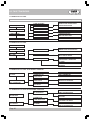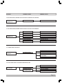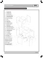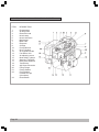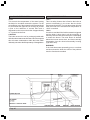
1
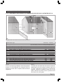
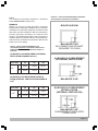
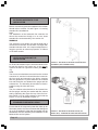
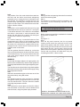
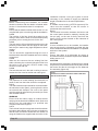
Jetstreme
Floor Standing Oil Boiler
Jetstreme 55
• INSTALLATION AND COMMISSIONING INSTRUCTIONS
• SERVICE AND MAINTENANCE PROCEDURES
• USER MANUAL
This document is to be left with the user following installation
CONTENTS
1.0
1.1
1.2
1.3
1.4
1.5
1.6
1.7
General Product Information
Introduction
Compliance Notices
Safety Definitions
Materials Selection
General Product Information
Warranty
Warranty Terms & Conditions
4.0
4.1
4.2
4.3
4.4
4.5
4.6
4.7
Commissioning
Pre-Commissioning Inspection of the Installation
Pre-Commissioning Inspection of the Boiler
Pre-Commissioning Inspection of the Burner
Pre-Firing Checks
Firing the Boiler
Combustion Checks
Hand Over
2.0
2.1
2.2
2.3
2.4
2.5
2.6
2.7
2.8
2.9
2.10
2.11
2.12
2.13
2.14
2.15
Pre-Installation Requirements
Compliance Notices
Pre-Installation Checks
Damaged or Missing Parts
Locating and Positioning Boiler
Fuel
Fuel Supply
Storage Tank
Fuel Supply - Single Pipe System
Fuel Supply - Two Pipe System
Single Pipe System with De-Aeration Devices
Pipework and Fittings
Electrical Supply
Balanced Flue Position
Conventional Flue
Ventilation Requirements
5.0
5.1
5.2
5.3
5.4
5.5
Servicing
Servicing - General Requirements
Servicing - Oil Installation
Servicing - Boiler
Servicing - Burner
Servicing - Re-Commissioning
6.0
Faults Diagnosis
7.0
7.1
7.2
7.3
7.4
Wiring Diagrams
With Optional Programmer
No Integral Programmer
Typical ‘S’ Plan
Typical ‘Y’ Plan
8.0
Technical Data for Kerosene Models
3.0
3.1
3.2
Installation BF and CF Models
Boiler Installation
Balanced Flue
9.0
9.1
9.2
9.3
9.4
9.5
Parts Listing
Parts Identification and Diagram - 55 & 80 Models
Boiler Parts Diagram - 55 & 80 Models
Parts Identification - 125 Model
Parts Diagram - 125 Model
Parts Identification and Diagram - Burner
10.0
10.1
10.2
10.3
10.4
10.5
10.6
10.7
10.8
10.9
User Information
Introduction
Programmable Timer
Boiler Thermostat
Limit Thermostat
Neon lamps and Burner ‘Lockouts’
Burner Problems
Servicing
Routine Cleaning and Maintenance
Useful Information
55 & 80 Models only - Standard Flue Installation
3.3
Balanced Flue
55 & 80 Models only - LH & RH Flue Installation
3.4
Balanced Flue
55 & 80 Models only - Extended Horizontal Flue Installation
3.5
Balanced Flue
55 & 80 Models only - Vertical Extension Flue Installation
3.6
Balanced Flue
125 Model only - Standard Flue Installation
3.7
Balanced Flue
125 Model only - LH & RH Flue Installation
3.8
Balanced Flue
125 Model only - Extended Horizontal Flue Installation
3.9
Balanced Flue
125 Model only - Vertical Extension Flue Installation
3.10 Conventional Flue - All Models
3.11 Connection of Services
11.0 Commissioning Report Form
Page 1
1.0 GENERAL PRODUCT INFORMATION
1.1 INTRODUCTION
1.1.1
Halstead Boilers is continuously improving its
products and may therefore change specifications
without prior notice. The statutory rights of the
consumer are not affected.
1.1.2
Whilst every reasonable care has been taken to
ensure that the information provided with each
appliance is true, accurate, and up to date, the
manufacturer will not accept liability for any claims
arising through inadvertent errors or omissions
relating to the information detailed herewith.
1.2 COMPLIANCE NOTICES
1.2.1
The Jetstreme range of oil fired domestic boilers
detailed herewith is manufactured by Halstead
Boilers within a strictly controlled quality environment
to ISO 9001.
1.2.2
The Jetstreme range has been subjected to rigorous
independent testing, and has been found to meet
The Essential Requirements of the following
European Directives:Machinery Directive (89/392/EEC)
Low Voltage Directive (73/23/EEC & 93/68/EEC)
E.M.C. Directive (89/336/EEC & 91/31/EEC)
Boiler Efficiency Directive (SI 1993 / 3083)
1.2.3
In accordance with the terms of the Product Liability
Directive (65/374/EEC) the manufacturer has taken
reasonable and practical steps to ensure that the
Jetstreme range of domestic boilers are safe and
pose no risk when properly used. The appliances
should therefore only be used in the manner and for
the purpose for which they were intended, and, in
accordance with the recommendations detailed
herewith.
Page 2
1.2.4
The range has been produced with safety and quality
in mind. There are certain basic precautions which
the installer, commissioning engineer, service
engineer, and user should be aware of. They are
strongly advised to read the relevant parts of this
manual prior to undertaking installation, adjustment,
or use.
1.2.5
Halstead Boilers supports all new products with a
comprehensive information pack which defines
mandatory instructions for the safe installation,
maintenance, and use of their appliances. Where
proprietary items are incorporated within Halstead
Boilers’ products, detailed information and
instructions are also provided as part of the
information pack.
1.2.6
It is the responsibility of the installer, commissioning
engineer, service engineer, and the user, to ensure
that they are familiar with, and understand, the
relevant instructions and information contained within
this manual.
1.3 SAFETY DEFINITIONS
1.3.1
Contained within the text of the manual, the words
‘Caution’ and ‘Warning’ are used to highlight certain
points.
1.3.2
Caution is used when failure to follow or implement
the instruction(s) can lead to premature failure or
damage being sustained to the appliance or its
component parts.
1.3.3
Warning is used when failure to heed or implement
the instruction(s) can lead to component damage
accompanied by a possible hazardous situation being
created, where there is a risk of personal injury being
sustained.
1.4 MATERIALS SELECTION
1.4.1
Neither asbestos nor soft soldered joints are used
in the construction of the Jetstreme range of
domestic boilers. The materials selected for use
can withstand the mechanical, chemical, and
thermal stresses which they will be subject to
during foreseen normal use, and when installed
and maintained in accordance with the
manufacturers recommendations.
1.5.3
Insulation is attached on the inside of the case.
The case is finished in white powder coat enamel
and is styled to blend into any kitchen.
1.5.4
The Jetstreme range can be specified in either
conventional or balanced flue configuration. Standard
units are designed to fire using kerosene (28 second
class C2) fuel oil.
A combustion test point is located in the top front of
the boiler shell to enable the commissioning engineer
to carry out his commissioning checks at a
convenient point.
Commissioning should take place within seven days
of installation.
1.5.5
All boilers will operate quite satisfactorily within a
system featuring gravity fed hot water and pumped
central heating. It is deemed preferable if both the
hot water and central heating systems are pumped,
given that the maximum pressure within such an
installation does not exceed 3 bar (45 psi).
1.5 GENERAL PRODUCT INFORMATION
1.5.1
The Jetstreme range of oil fired boilers combine the
benefits of advanced design with well proven
construction techniques and modern manufacturing
processes.
1.5.2
The range offers; a user and maintenance friendly
design, reliability, efficient and clean combustion, and
low operating noise levels.
The controls are enclosed behind a metal hinged
panel on the front of the appliance thus reducing
possible accidental damage to them.
The controls comprise of:(1) ON / OFF Switch.
(2) THERMOSTAT Control,
(3) OVERHEAT Thermostat manual reset which
will automatically switch off the boiler if it
exceeds a set temperature (103 deg)
(A DIGITAL PROGRAMMER is available as
an optional extra)
Page 3
1.6 WARRANTY
1.6.1
Each boiler is supplied with a one year peace of mind
guarantee against manufacturing or material defects.
The warranty is conditional upon the appliance having
been installed, commissioned and used in accordance
with the manufacturers recommendations.
1.6.2
A Commissioning Report and Warranty Registration
form is at the back of this manual. This form must be
completed and returned to Halstead Boilers within
seven days of commissioning having taken place. It
should be noted that claims under warranty may not
be processed unless the terms and conditions of the
warranty are strictly adhered to.
1.7 WARRANTY TERMS AND CONDITIONS
1.7.1
Any part manufactured by Halstead Boilers which
fails due to defective materials or poor workmanship
within twelve months from the installation date of the
boiler will be repaired or replaced free of charge
inclusive of parts and labour.
1.7.2
Consumable items are specifically excluded from the
terms of the warranty.
1.7.3
In order that the warranty can be established, the
Commissioning Report and Warranty Registration
Form (at the rear of this manual) must have been
completed in full and returned to the service
department at Halstead Boilers within seven days
from commissioning having been undertaken. Any
warranty claims made without this condition being
fulfilled will not be processed.
Page 4
1.7.4
The Jetstreme must be installed, commissioned, and
used, in accordance with the guidelines contained
within this manual. Failure to comply with this
requirement will invalidate the warranty.
1.7.5
Commissioning must take place within seven days
from the date of installation. Failure to comply with
this requirement may invalidate the warranty.
1.7.6
The warranty does not cover claims arising from or
associated with normal wear and tear, neglect,
misuse, improper installation, ineffective
commissioning, or poor maintenance.
1.7.7
The warranty applies to Halstead Boilers that remain
to the manufacturer’s specification. Unauthorized
modification or deviations will invalidate the warranty.
1.7.8
The warranty terms and conditions do not affect the
statutory rights of the customer.
1.8 WARRANTY CLAIMS
1.8.1
In the first instance any claim under warranty should
be addressed to the service department at Halstead
Boilers.
1.8.2
Subject to the details outlined previously in section
1.7 ‘Warranty terms and conditions’, if appropriate
Halstead Boilers will bear the cost of necessary
replacement parts and labour, provided that the faulty
component is returned on a carriage paid basis to
Halstead Boilers.
2.0 PRE-INSTALLATION REQUIREMENTS
Prior to installation the site should be surveyed and
checked to ensure that it is suitable for the appliance,
and also to ensure that installation, commissioning,
and maintenance can be carried out safely and
effectively, and in accordance with the manufacturer’s
recommendations.
2.1 COMPLIANCE NOTICES
2.1.1
It is a requirement that only competent oil boiler
installation engineers should commission Jetstreme
boilers.
2.1.2
Under the terms of the current Health and Safety at
Work legislation it is a requirement that the installer
affords adequate protection to the person(s) carrying
out the installation, and others within the location.
2.1.3
The installation must comply with any specific
insurance criteria relevant to the site or installation.
2.1.4
Local, national, and European regulations must also
be observed, and this must include compliance with
building regulations and any appropriate bye laws,
as well as compliance with IEE and European
electrical standards and regulations.
2.1.5
The manufacturer encourages the installer to work
within recognised standards. Details of certain of the
applicable standards are available from Halstead
Boilers.
2.3 DAMAGED OR MISSING PARTS
2.3.1
Any damaged parts or shortages must be noted and
the details provided to the service department at
Halstead Boilers immediately. This procedure is
necessary in order to comply with the insurance
criteria, and will ensure that the matter is allocated a
priority status
2.2 PRE-INSTALLATION CHECKS
2.2.1
The installer should ensure that the model is to the
specification agreed with the customer, and that all
parts are present. Care should be exercised when
moving the boiler so as not to damage either the unit
or any of its ancillary parts. It is preferable to remove
the packaging only when the boiler is ready to be
installed, thereby reducing the risk of accidental
damage occurring. When the packaging is removed
the boiler and ancillary parts should be visually
inspected to ensure that they have not been subject
to transit damage.
Page 5
2.4 LOCATING AND POSITIONING BOILER
2.4.1 THE HEATING INSTALLATION
• The installation should be installed in
accordance with the requirements of BS 5449
and provisions recommended by the HVCA.
• Water circulation through the boiler may be totally
or appreciably reduced by the application of some
modern controls systems and still allow the boiler
to fire. This may result in the boiler controls not
being able to sense excessive or boiling
temperatures, and switch the boiler off. Should
this condition be possible, it is important to see
that the controls are wired so that the power supply
to the burner and circulating pump are
simultaneously switched off.
• With an existing heating installation, if the boiler
is a replacement, it is important to see that due
consideration is given to replacing the chimney
lining or factory made chimney, and the existing
oil supply tank. As these may well not serve the
new installation due to their condition and
specification.
2.4.2 THE HEATING SYSTEM
• Prior to replacing an existing oil boiler, please
ensure that the system is chemically cleaned of
scale and debris. Refer to reputable manufacturer
for advice.
• The system must be flushed clean prior to filling
and must contain clean water, it should be
inspected and seen to be free of leaks.
• Suitable chemical inhibitors to protect against lime
scale and corrosion must be added to the system
prior to the first firing of the boiler.
• Kettling and persistent system noises can
generally be avoided by the application of suitable
proprietary pre-treatments from the start.
2.4.3 GENERAL INSTALLATION DETAILS FOR
BALANCED FLUES
• Flue kits for low level must only be used with
Kerosene applications.
• A terminal guard must be fitted where the flue
terminal can be touched under normal
circumstances.
• Please remove any protective film on the stainless
steel surfaces, before locating the flue terminal
through the wall.
Models 55 and 80 can only use the high level
balanced flue kit for REAR OUTLET ONLY.
Page 6
2.4.4
All Jetstreme boilers should be installed on a level noncombustible surface which is capable of supporting
the weight of the appliance and any ancillary parts. It
is recommended that the installer ensures that there
is adequate clearance to accommodate service
requirements, this will also serve to provide useful
access during installation. The recommended
clearances are detailed below.
RECOMMENDED CLEARANCES
Above the boiler
600mm
Left hand side
25mm
Right hand side
25mm
In front
900mm
2.4.5
Provision must be made for the connection of the
fuel supply, electrical supply, and for flueing
arrangements.
2.4.6
If the unit is specified as a conventional flue model
provision must be made for adequate ventilation to
be introduced to the area so as to ensure safe and
efficient combustion. If the model features a balanced
flue then the proposed position should be checked
so as to ensure that it complies with the
manufacturers recommendations and with the
appropriate building regulations.
2.4.7
Consideration must also be given to the position of
ancillary pipe work for central heating and domestic
hot water which will have to be connected to their
respective points on the boiler.
2.5 FUEL
CAUTION
All Jetstreme boilers are manufactured to be used
with 28 second fuel oil to class C2 (kerosene).
WARNING
Prolonged contact with fuel can result in the natural
oils within the skin being removed. Always wear the
appropriate personal protective equipment. Health
and safety data sheets are available from the fuel
supplier.
2.6 FUEL SUPPLY
2.6.1
The fuel supplier should be contacted prior to
installation so that any concerns regarding delivery,
transport, access, and storage can be addressed. The
supplier will also be able to advise on price/quantity
breaks which can have an influence upon the most
appropriate size of storage tank.
2.6.2
The constraints of the site will to a large extent
determine whether the oil feed to the boiler is either
of the single pipe gravity feed type, or whether it is
necessary to use a twin pipe system.
WARNING
The site chosen for the storage tank must comply with
all the appropriate regulations, it is further suggested
that BS 5410 parts 1 and 2 are consulted.
EXTERNAL OIL STORAGE TANK PROTECTION FOR
SINGLE FAMILY DWELLINGS
BS 5410 PART 1: 1977. FOR TANKS NOT EXCEEDING 3400 LITRES
2.7 STORAGE TANK
2.7.1
The oil storage tank must conform to the appropriate
standard; for an externally painted steel vessel this will
be to BS 799 part 5 1987, and, in the case of the more
modern low density polyethylene tank, this must be
OFTEC certified to OFS T-100. The use of open lids
as a means of filing is not approved. A 50mm diameter
black iron pipe terminating with a 50mm BSP male
thread hose coupling and a non-ferrous screw cap
with chain is essential (See OFTEC Book 3)
2.7.2
Masonry piers should be used to support steel oil
storage tanks with the interface between the pier and
the tank isolated using a damp proof membrane.
2.7.3
The tank must be positioned so that it slopes away
from the outlet by 20mm per 1m thereby ensuring
that impurities do not contaminate the feed. These
impurities must be removed during maintenance or
servicing to prevent them from building up and
entering the feed.
CAUTION
Steel tanks should be painted only on their outside
surfaces, preferably using a proprietary grade of anticorrosive paint. Galvanized or open topped tanks are
not suitable and must not be used.
2.7.4
The oil storage tank should be fitted to include the
following; fuel level gauge, a vent pipe (with a diameter
greater than the diameter of the filler) and featuring a
weather proof termination, a sludge valve, an outlet valve
situated at the opposite end of the tank to the sludge
valve, and, a filler connection placed at the opposite end
to the outlet valve.
FIG 1
EXTERNAL OIL STORAGE TANK CLEARANCES FOR
SINGLE FAMILY DWELLINGS
BS 5410 PART 1: 1977. FOR TANKS NOT EXCEEDING 3400 LITRES
FIG 2
Illustrations taken from OFTEC Technical Information Book 3.
Page 7
2.8 FUEL SUPPLY SINGLE PIPE SYSTEM
2.8.1
For installations where the oil storage tank is at least
300mm above the level of the fuel pump on the
burner, the principle of gravity feed may be used.
The bore and length of run for the fuel feed to the
burner is detailed in Table 1. It should be noted that
all Jetstreme boilers are pre-fired and set up to run
using a single pipe gravity feed system as detailed
below, in figure 3.
FIG 3
Illustration taken from OFTEC Technical Information Book 3
TABLE 1
TABLE 2
DIAMETER X DISTANCE X HEIGHT TABLE
DIAMETER X DISTANCE X HEIGHT TABLE
(A) SINGLE PIPE SYSTEM FUEL FEEDS
(B) TWO PIPE SYSTEM FUEL FEEDS
Pipe O/D Height X length (m)
12mm 0.5 x 20 1.0 x 40 1.5 x 80
10mm 0.5 x 10 1.0 x 20 1.5 x 40
Pipe O/D Height X length (m)
12mm 0.0 x 100 0.5 x 100 1.0 x 100 1.5 x 90
2.0 x 70 3.0 x 30 3.5 x 20
0.0 x 35 0.5 x 30 1.0 x 25 1.5 x 20
10mm 2.0 x 15 3.0 x 8
3.5 x 6
Page 8
2.0 x 100
2.0 x 60
2.9 FUEL SUPPLY TWO PIPE SYSTEM
2.9.2
This system is used when the oil storage tank is at
the same level or lower than the burner (see figure
4). Access for the fuel feed to the burner should be
via a suitable tapping made in the top of the tank,
through which the feed pipe must extend to not less
than 100mm from the bottom of the tank. A non-return
valve with a metal to metal seat should be fitted,
especially if the return pipe is terminated above the
draw off tube. The non-return valve must be
removable for service and
maintenance purposes, and
the return pipe from the
pump must therefore be
extended into the tank to the
same level as the suction
pipe. The presence of a
tamper proof isolating valve
fitted within the line is only
necessary if there is a risk
that oil will siphon out of the
tank if the return pipe is
(b) TWO PIPE SYSTEM
BOTTOM OF OIL STORAGE TANK BELOW OR LEVEL WITH BURNER
disconnected at the pump
during maintenance or
servicing, or if the non-return
valve has been omitted.
2.9.1
All Jetstreme boilers are fitted with pressure jet burners
as standard, which means that the pump fitted within
the packaged burner can be used to raise the fuel up
to provide a suction feed to the burner if the tank is
not above the level of the burner. This can be facilitated
either via a two pipe system or by means of a single
pipe system fitted with a de-aeration device. The bore
and length of the run for the fuel feed to the burner is
detailed in Table 2.
FIGURE 4 -
2.10 SINGLE PIPE
SYSTEM WITH DEAERATION DEVICE
FIGURE 5 - (c) SINGLE PIPE SYSTEM WITH DE AERATION DEVICE
BOTTOM OF OIL STORAGE TANK BELOW OR LEVEL WITH BURNER
2.10.1
Alternatively, where the tank
is at the same height or lower
than the burner a single pipe
feed to a de-aeration device
with twin pipe to/from the
burner may be used. See
Figure 5.
Illustrations taken from OFTEC Technical Information Book 3
CAUTION
Before installation the position of the oil pump bypass plug and horse shoe shaped washer must be
checked. If the plug and washer is fitted then the
pump is set for a single pipe system. It should be
noted that this is normally the case. If so, the plug
and washer must be removed, and the plug replaced
without the washer, rendering the unit acceptable for
a two pipe system.
CAUTION
The pump vacuum must not exceed 0.4 bar otherwise
nuisance burner lockouts may occur as a result of
starvation attributed to gas formation within the oil.
2.10.2
These are sometimes referred to as ‘Tiger Loops’
and their installation must be in accordance with the
manufacturer’s recommendations (Fig. 5).
Page 9
2.11 PIPEWORK AND FITTINGS
CAUTION
Galvanized pipework and fittings must not be used.
Any joints must be sealed properly using PTFE or
other approved sealing media to prevent both fuel
leakage and the ingress of air.
2.11.1
Normally oil supply pipework consists of annealed
copper tube, which has the advantage of being easily
manipulated to form bends, and enables the line to
be run in continuous lengths without joints. This tube
is available with a durable plastic sheath ready fitted
for added protection.
2.11.2
Where pipes are buried it is important that they are
offered adequate protection from accidental damage,
and that high points (which could cause air locks)
are avoided. All pipework must be adequately
supported.
2.11.3
It is preferable that all pipework should be run with a
slight but continuous rise towards the direction of flow,
so that any air can be vented off.
WARNING
It is a requirement that a fire check valve is present
within the system. This may be of either the weight
operated type or the capillary operated type.
CAUTION
It is a requirement that an oil filter is fitted within the
supply line. Its position should be such that it can be
isolated for maintenance and servicing without having
to drain down the system.
Page 10
2.12 ELECTRICAL SUPPLY
WARNING
All Jetstreme boilers must be earthed. The electrical
supply must be made via a 6A fused double pole
isolation switch with a separation distance of at least
3mm between contacts. All conductors must have a
cross sectional area of at least 0.75mm2.
2.12.1
All wiring and electrical work must be carried out by
a competent electrician and must be in compliance
with current IEE regulations.
2.13 BALANCED FLUE POSITION
2.13.1 POSITIONS OF BALANCED FLUE TERMINALS SHOULD BE AS ILLUSTRATED IN FIG. 6
FIG 6
Illustration taken from OFTEC Technical Information Book 3
Appliance burner type
Pressure jet
Vaporising
Minimum distances to terminals in millimetres as measured from
top of the chimney or the rim of a low level discharge opening
A
B
C
D
E
F
G
H
J
K
L
M
N
O
P
Directly below an opening, airbrick, window etc.
Horizontally to an opening, air brick, window etc.
Below a gutter, eaves or balcony with protection
Below a gutter, or a balcony without protection
From vertical sanitary pipework
From an internal or external corner
Above ground or balcony level
From a surface or a boundary facing the terminal
From a terminal facing the terminal
Vertically from a terminal on the same wall
Horizontally from a terminal on the same wall
Above the highest point of an intersection with the roof
From a vertical structure on the side of the terminal
Above a vertical structure less than 750mm from the side of the terminal
From a ridge terminal to a vertical structure on the roof
2.13.2
Prior to commencing installation work the proposed
position for the balanced flue terminal must be
checked to ensure that it complies with the relevant
regulations.
600
600
75
600
300
300
300
600
1200
1500
750
600
750
600
1500
Not allowed
Not allowed
Not allowed
Not allowed
Not allowed
Not allowed
Not allowed
Not allowed
Not allowed
Not allowed
Not allowed
1000
2300
1000
Not allowed
2.13.3
It should also be noted that the terminal should be
positioned so as not to cause a nuisance, and so as
to allow unimpaired dispersal of combustion
products. Where the terminal is within 1m of any
plastic material the plastic must be protected from
the effects of the flue gases.
Page 11
2.14 CONVENTIONAL FLUE
2.14.1
The flue should rise as vertically as possible and
terminate at a point where it will not be subject to
down draughts or eddies as illustrated in Figure 7. If
an existing traditional chimney is to be used then it
must be lined with a moisture and acid resistant flue
liner of the same diameter as the flue spigot on the
boiler. The connecting lengths of flue from the boiler
spigot to the flue liner should be of twin wall type. It
is recommended that the existing chimney is backfilled around the flue liner with vermiculite so as to
retain the heat, maintain boiler efficiency, and prolong
the working life of both the boiler and the flue liner.
CAUTION
If an existing chimney is to be used it must be cleaned
thoroughly, with all soot and scale removed prior to
the liner being installed.
2.14.2
Where a traditional flue has been lined with a large
section clay flue liner it will be necessary to fit a metal
flue liner so as to reduce the bore and improve the
thermal insulation. Again, once the flue liner is in
position it should be back-filled with vermiculite.
WARNING
If an existing flue liner is already fitted its condition
must be checked to ensure that it is satisfactory.
Flexible flue liners usually have an effective working
life greater than that of the boiler, but it is rare that
this working life is equal to twice that of the boiler. It
is therefore recommended that when a new boiler is
installed a replacement flue liner is also fitted.
WIND
DIRECTION
FIGURE 7 - TYPICAL PRESSURE ZONES EFFECTING
CONVENTIONAL FLUES
Page 12
2.14.3
When it is not possible to utilise an existing chimney
a twin wall stainless steel flue may be used instead.
In this case the number of bends must be kept to an
absolute minimum, and the flue must rise vertically.
The internal diameter of the twin wall flue must be
the same as that on the boiler flue spigot. It is
suggested that the relevant sections of BS 5440 part
1, BS 5854 and BS 4543 part 3 are referred to (see
figure 8-internal, figure 8A-external).
2.14.4
Where single skin flue is to be used consideration
must be given to the possible problems associated
with the formation and entrapment of condensates.
It is therefore strongly recommended that the
maximum length of single skin flue is not greater than
6m, and an adequate drain facility is included in the
flue design.
FIG 8
C
FIG 8A
Page 13
2.15 VENTILATION REQUIREMENTS
The current requirements detailed within Figures 9
and 10 are based upon BS 5410 part 1 for a free
area of non closable ventilation and are based on
550mm 2 per kW output and multiples thereof
depending upon the application.
2.15.1
The following information applies to Jetstreme
boiler conventional flue models only.
FIGURE 9 - VENTILATION REQUIREMENTS (INTERNAL
AND EXTERNAL) CONVENTIONAL FLUE MODELS.
FIGURES SHOWN ARE NON-CLOSABLE VENTILATION IN
mm2 PER KW OUTPUT OF BOILER.
(A) BOILER IN ROOM
TABLE 3 - VENTILATION REQUIREMENTS FOR
CONVENTIONAL FLUE BOILERS (BS 5410 PART 1). SEE
ILLUSTRATIONS IN FIGURE 9 OPPOSITE.
(A) BOILER IN A ROOM (EXTERNAL VENTILATION
REQUIRED IN mm2)
OPEN AREA
55
80
125
in
8855
12870
20130
out
0
0
0
CONVENTIONAL FLUE
mm2
(B) BOILER IN A COMPARTMENT (EXTERNAL
VENTILATION REQUIRED IN mm2)
OPEN AREA
55
80
125
in
17710
25740
40260
out
8855
12870
20130
(B) BOILER IN COMPARTMENT
mm2
(C) BOILER IN A COMPARTMENT WITHIN A
ROOM (INTERNAL AND EXTERNAL VENTILATION
REQUIRED IN mm2)
OPEN AREA
55
80
125
8855
12870
20130
0
0
0
(i) in
26565
38610
60390
(i)out
17710
25740
40260
(e)in
(e)out
mm2
WARNING
The provision of adequate ventilation is necessary
in order to facilitate safe and efficient operation of
the boiler. If an extraction unit is fitted within the same
area, the amount of ventilation required will have to
take account of this if the extraction unit effects
combustion.
Page 14
CONVENTIONAL FLUE
(C) BOILER IN COMPARTMENT
WITHIN A ROOM
(e)
(i)
CONVENTIONAL FLUE
2.15.2
The following information applies to Jetstreme
boiler balanced flue models only.
WARNING
Whilst it is correct to state that when Jetstreme
balanced flue models are installed they do not require
ventilation for combustion purposes, it must be noted
that under certain conditions it will be necessary to
provide adequate ventilation for balanced flue
models. This applies particularly when the boiler is
installed within a confined space or a compartment,
and where the ventilation is provided to prevent the
boiler from over heating.
TABLE 4 - VENTILATION REQUIREMENTS FOR
JETSTREME BALANCED FLUE MODELS INSTALLED IN
COMPARTMENTS. SEE ILLUSTRATIONS IN FIGURE 10
OPPOSITE.
(A) BOILER IN A COMPARTMENT (EXTERNAL
VENTILATION REQUIRED IN mm2)
Open Area
mm
55
80
125
in
8855
12870
20130
out
8855
12870
20130
FIGURE 10 - VENTILATION REQUIREMENTS (INTERNAL
AND EXTERNAL) BALANCED FLUE MODELS
BOILER IN ROOM
BALANCED FLUE
NO COMBUSTION AIR INLET
REQUIRED TO ROOM
(A) BOILER IN COMPARTMENT
(EXTERNAL VENTILATION)
2
(B) BOILER IN A COMPARTMENT WITHIN A
ROOM (INTERNAL VENTILATION REQUIRED IN
mm2)
Open Area
55
80
125
in
17710
25740
40260
out
17710
25740
40260
mm2
BALANCED FLUE
(B) BOILER IN COMPARTMENT
WITHIN A ROOM
(INTERNAL VENTILATION)
BALANCED FLUE
COMPARTMENT VENTILATED
FROM ROOM
Page 15
3.0
INSTALLATION
BALANCED
FLUE
AND
3.0.0
INSTALLATION
BF AND CF
MODELS
CONVENTIONAL FLUE MODELS
3.1 BOILER INSTALLATION
3.1.1
The packaging should be carefully removed from
around the boiler and the flow and return fittings
secured in their appropriate positions.
3.1.2
If only one flow and return is to be fitted then it is
preferable that these are positioned so that the flow is
above and diametrically opposite the return.
3.1.3
The boiler should be placed in position and the top
and front panels removed, by lifting upwards and
outwards respectively.
3.2.5
The two gaskets should be offered up so that the
first is positioned between the boiler and the exterior
of the exhaust box, and the second, between the
male end of the flue spigot and the interior of the
exhaust box.
3.2 BALANCED FLUE – 55 & 80 MODELS ONLY
STANDARD FLUE INSTALLATION
CAUTION
Before commencing with the installation, the installer
should be familiar with and ensure compliance with the
electrical supply details contained within section 2.12
3.2.1
Ensure that all the component parts that make up
the balanced flue kit are present, (See Figure 11). It
is also recommended that the figures 11 through to
16 are studied in order that the installer might be
familiar with the assembly and installation of the
balanced flue and its options.
3.2.2
The position of the flue outlet should be marked on
the wall, and the boiler moved and adequately
protected, prior to cutting the hole in the wall for the
flue outlet. On completion of cutting the hole, the flue
outlet box should extend through the wall so as to
allow the air intake slots to project by at least 25mm,
(See Figure 12).
3.2.3
If the boiler is to be installed with either a left hand or
right hand balanced flue exit then section 3.3 and
figure 13 should be referred to. If the boiler is to be
installed with a horizontal or vertical extension then
sections 3.4 and figure 14 or 3.5 and figure 15 should
be referred to respectively.
3.2.4
On models featuring a standard balanced flue
arrangement, as in figure 11, the installation should
continue as follows. Remove the access plate from
the inside end of the flue outlet box, together with the
four hexagonal nuts screwed onto the studs around
the exhaust outlet on the boiler.
Page 16
FIGURE 11 - BALANCED FLUE INSTALLATION
55 & 80 MODELS ONLY (STANDARD KIT SUPPLIED WITH BOILER)
WARNING
Ensure that the flue spigot, the upper gasket, the
balanced flue exhaust box, and the lower gasket are
correctly positioned before tightening and securing
the nuts.
3.2.6
The flue exhaust duct should then be pushed
together and sealed securely at the correct length
using the sealing tape provided.
3.2.7
The outer case can now be sealed with the tape
provided.
3.2.8
The exhaust box access plate can then be refitted,
and the flexible air inlet tube secured to both the
exhaust box access plate and the burner, using the
jubilee clips provided.
3.2.9
When the hole that was cut in the wall to
accommodate the balanced flue has been made
good, the protective basket should be fitted and
screwed to the wall.
3.2.10
On satisfactory completion of the flue installation,
the connection to other services can be undertaken
as detailed in section 4.0
FIG 12
3.3 BALANCED FLUE – 55 & 80 MODELS
ONLY LH AND RH FLUE
IINSTALLATIONS
FIGURE 13 - BALANCED FLUE INSTALLATION LH AND
RH ORIENTATION LEFT HAND SHOWN. (55 & 80 MODELS
ONLY).
CAUTION
Before commencing with the installation the installer
should refer to section 3.2
3.3.1
If the balanced flue is to be positioned at right angles
to the boiler, then the blanking plate from the
appropriate side panel of the boiler must be removed.
WARNING
The flue outlet assembly air inlet slots must have
a minimum projection from the surface of the
outside wall of 25 mm, (as Figure 12).
3.3.2
When the hole that was cut in the wall to
accommodate the balanced flue has been made
good, the protective basket should be fitted and
screwed to the wall.
3.3.3
On satisfactory completion of the flue installation,
the connection to other services can be
undertaken as detailed in section 4.0.
FIGURE 14 - BALANCED FLUE
HORIZONTAL EXTENSION KIT (55 & 80 MODELS ONLY).
Page 17
3.4 BALANCED FLUE – 55 & 80 MODELS EXTENDED HORIZONTAL FLUE
INSTALLATION
CAUTION
Before commencing with the installation the installer
should refer to section 3.2 and Figure 14 covering
standard flue installations.
3.4.1
The installation of the balanced flue extension kit
should be treated as though it is an over sized
standard flue outlet assembly. See section 3.2
WARNING
The extension cover slides over the terminal and is
cemented into the wall, and as there is a larger than
standard exhaust tube, this requires adjustment to
length to provide an external projection of 200mm
on 55 & 80 models.
3.5 BALANCED FLUE – 55 & 80 MODELS ONLY
VERTICAL EXTENSION FLUE
INSTALLATION
3.5.1
On 55 and 80 models only the Vertical extension flue
kit may be used for rear outlet only. It may not be
used for left hand or right hand outlets, (See Figure
15).
3.5.2
The front cover should be removed from the vertical
extension kit, and the kit should then be located on
the four studs and secured to the boiler, ensuring
that the gaskets are in place between the exhaust
box and the boiler, and between the spigot and the
exhaust box. The assembly should then be fixed in
position using the nuts and studs.
3.5.3
The flue exhaust tube should then be inserted into
the flue spigot, and the joint sealed with fire cement
and by tightening the clip at the top of the flue box.
Now follow 3.2.4 as if fitting directly to the boiler as
Figure 11, but as illustrated in figure 15.
FIGURE 15 - BALANCED FLUE INSTALLATION VERTICAL
EXTENSION. (55 & 80 MODELS ONLY).
3.6 BALANCED FLUE – 125 MODEL ONLY
STANDARD FLUE INSTALLATION
3.6.1
Ensure that all the component parts that make up the
flue kit are present. It is also recommended that figures
16 to 19 are studied in order that the installer may be
familiarised with the assembly and installation of the
balanced flue and its options.
Page 18
FIGURE 16 - BALANCED FLUE INSTALLATION. (125
MODEL ONLY) - STANDARD KIT SUPPLIED WITH BOILER.
3.6.2
The position of the flue outlet should be marked on
the wall, and the boiler moved and adequately
protected, prior to cutting the hole in the wall for the
flue terminal. On completion of cutting the hole, the
terminal body should pass through the wall and
project at least 70mm. The exhaust tube must then
project a further 125mm.
3.6.3
If the boiler is to be installed with either a left or right
hand balanced flue exit, then section 3.7 and figure
17 should be referred to. If the boiler is to be installed
with either a horizontal or vertical extension then
section 3.8 with figure 18 or section 3.9 with figure
19 should be referred to respectively.
3.6.4
On models featuring a standard balanced flue
arrangement, as in figure 12, the installation should
continue as follows. Remove the access plate from
the inside of the exhaust box, together with the four
hexagonal nuts screwed onto the studs around the
exhaust outlet on the boiler.
3.6.5
The two gaskets should be offered up, so that the
first is positioned between the boiler and the exterior
of the terminal body. The second, between the male
end of the spigot adapter and the interior of the
terminal body.
3.6.10
Make good the wall opening about the flue terminal,
and fit the terminal guard.
3.6.11
On satisfactory completion of the flue installation, the
connection of the remaining services can be
undertaken.
3.7 BALANCED FLUE – 125 MODEL ONLY
RH & LH FLUE INSTALLATIONS
CAUTION
Before commencing with the installation the installer
should refer to section 3.6.
3.7.1
See figure 17.
3.7.2
With the top panel removed, the four top panel
locating studs should be removed from the side
panels and replaced with M5 x10mm screws. The
brass locating pins should also be removed from the
side panels and the control panel. With the side
panels and control panel in place the top panel can
now be slid into position and held there using the
remaining three M5 x 10mm screws.
WARNING
Ensure that the spigot adapter, the upper gasket, the
balanced flue terminal body, and the lower gasket are
correctly positioned before securing and tightening nuts.
3.6.6
The flue exhaust duct should then be pushed together
and sealed securely at its joint with the flue spigot, using
high temperature silicone.
3.6.7
Attach the wind deflector plate to the outer end of the
flue terminal body, using M5 screws.
3.6.8
The dished extension tube can then be inserted
throught the opening, and pushed home so as to slip
over flue exhaust duct. The joint should be sealed
using high temperature silicone.
3.6.9
The terminal box access plate can then be refitted,
and the flexible air inlet tube secured between this
and the burner, using the jubilee clips provided.
FIGURE 17 - BALANCED FLUE INSTALLATION LH & RH
ORIENTATION (125 MODEL ONLY). RIGHT HAND SHOWN.
Page 19
3.7.3
With the top panel removed the installation should
continue as follows: Remove the access plate from
the end of the exhaust box, together with the four
hexagonal nuts screwed onto the studs around the
exhaust outlet on the boiler
3.7.4
The first gasket should be offered up so that it is
positioned between the boiler and the exterior of the
lower part of the transition box. The second gasket
should be placed within the lower part of the transition
box, which should then be located upon the studs
around the boiler exhaust outlet, ensuring that the
air feed spigot is facing forward.
3.7.5
The flue spigot should be pushed home; through the
top gasket, and through the lower part of the transition
box and lower gasket, and into the exhaust outlet on
the boiler. This assembly should then be clamped
using the nuts and stud fixings from the boiler.
WARNING
Ensure that the lower transition box assembly and both
gaskets are correctly located prior to clamping into
position.
3.7.6
The exhaust extension should then be pushed into the
flue spigot, and sealed in place using high temperature
silicone. This should also be applied to the inner surface
of the opposite end of the exhaust extension, in
preparation for the joint with the exhaust pipe silencer.
3.7.7
The top plate from the transition box should then be
fitted using the self tapping screws.
3.7.8
The exhaust extension and exhaust pipe silencer should
be pushed together firmly, and the joints sealed using
high temperature silicone.
3.7.9
The flue box, with the gasket in position, should be
offered up to the transmission box, and using the four
M6 screws the parts should be clamped. Care must be
taken to ensure that the integrity of the gasket is
maintained.
3.7.10
The flue exhaust duct should then be pushed into and
sealed securely at its joint with the flue extension, using
high temperature silicone.
3.7.11
Attach the wind deflector plate to the outer end of the
flue terminal using the M5 screws.
Page 20
3.7.12
The dished extension tube can then be inserted
through the opening, and pushed home so as to slip
over the flue exhaust duct. The joint should be sealed
using high temperature silicone.
WARNING
The exhaust box assembly must have a minimum
projection from the surface of the outside wall of 70mm.
The exhaust tube must then project a further 125mm.
3.7.13
Make good the wall opening about the flue terminal,
and fit the terminal guard.
3.7.14
On satisfactory completion of the flue installation, the
connection to the remaining services can be
undertaken.
3.8 BALANCED FLUE – 125 MODEL ONLY
EXTENDED HORIZONTAL FLUE
INSTALLATION
CAUTION
Before commencing with the installation the installer
should refer to section 3.6, and Figure 16 covering
Standard flue installation.
3.8.1
See figure 18.
3.8.2
The installation of the balanced flue extension kit
should be treated as though it is an oversized
standard flue outlet assembly. See section 3.6.
WARNING
The extension cover slides over the terminal and is
cemented into the wall, and as there is a larger than
standard exhaust tube, this requires cutting to a length
to provide an external projection of 125mm for the 125
model.
3.9 BALANCED FLUE – 125 MODEL ONLY
VERTICAL EXTENSION FLUE
INSTALLATION
CAUTION
Before commencing with the installation the installer
should refer to section 3.6.
3.9.1
See figure 19.
3.9.2
The front cover should be removed from the
extension kit, and the kit should then be located on
the four studs and secured to the boiler, ensuring
FIGURE 18 - BALANCED FLUE INSTALLATION
HORIZONTAL EXTENSION. (125 MODEL).
that the gaskets are in place between the exhaust
box and the boiler, and between the spigot and the
exhaust box. The assembly should then be fixed i
position using the nuts and studs.
3.9.3
The flue exhaust tube should then be inserted into
the flue spigot, and the joint sealed with fire cement
and by tightening the clip at the top of the flue box.
3.9.4
The horizontal section should then be passed through
the hole in the wall and married up with the vertical
extension piece, ensuring that the gasket between
the two parts is in place and that the fastenings are
securely clamped.
3.9.5
The exhaust silencer should be passed through the
hole and positioned into the top of the vertical flue
exhaust pipe. The two parts should be pushed
together and the joint sealed using high temperature
silicone.
3.9.6
The dished extension tube can then be inserted
through the opening, and pushed home so as to slip
over the flue exhaust duct. The joint should be sealed
using high temperature silicone.
WARNING
The flue terminal assembly must have a minimum
projection from the surface of the outside wall of 70mm.
The exhaust tube must then project a further 125mm.
3.9.7
Make good the wall opening about the flue terminal,
and fit the terminal guard.
3.9.8
Refit the front cover to the vertical flue section and
discard the flue end cover with air pipe adapter, fitting
the plain blanking cover supplied with the horizontal
section of the flue.
3.9.9
The exhaust box access plate can then be re-fitted,
and the flexible air inlet secured to both the exhaust
box access plate and the burner, using the jubilee clips
provided.
3.9.10
Make good the wall opening about the flue terminal,
and fit the terminal guard.
3.9.11
On satisfactory completion of the flue installation, the
connection to other services can be undertaken.
FIGURE 19 - BALANCED FLUE INSTALLATION
VERTICAL EXTENSION. (125 MODEL).
Page 21
3.10 CONVENTIONAL FLUE – ALL MODELS
CAUTION
Before commencing the installation, the installer
should be familiar with the details contained within
section 2.14 and should check for compliance.
3.10.1
Ensure that the details outlined within section 3.1 are
complied with prior to continuing with the installation.
3.10.2
The position of the flue should be marked on the
ceiling or wall, and the boiler moved and adequately
protected, prior to cutting the hole for the flue.
3.10.3
The first section of flue should be placed so as to be
positively located within the flue spigot on the boiler,
and the joint sealed using high temperature silicon
sealant.
3.10.4
The flue should be supported through the use of
brackets which should be installed as the flue is being
constructed.
3.10.5
When the flue connects into an existing flue liner
within a chimney the connecting lengths of flue from
the boiler to the flue liner must be made using
sections of twin wall flue.
3.10.6
The hole that was cut in the wall or ceiling to accommodate the flue must be sealed and made good.
3.11 CONNECTION OF SERVICES
3.11.1
The pipework for central heating and domestic hot
water to and from the boiler should be completed.
3.11.2
The mains electrical input should be connected within
the electrical control panel, ensuring that the wires
are secured and clamped. The cover to the panel
must be replaced and positively secured by its screw
and serrated washer.
WARNING
Ensure that the mains supply is isolated before
carrying out the electrical installation work. Such work
should only be undertaken by a qualified and
competent electrical engineer.
3.11.3
The fuel feed from the storage tank should have been
brought to within 450mm of the oil pump on the burner,
and the final connection should then be carried out
using the flexible tube supplied with the boiler. If the
Page 22
installation features a two pipe system it will be
necessary for the installer to supply an additional
length of flexible tube to the same specification.
3.11.4
A suitable remote acting (OFTEC Approved) Fire
valve must be installed so that the sensor is
positioned above the burner.
3.11.5
The electrical connection between the burner and
the control panel should be made by inserting the
four pin plug, on the end of the fly lead from the
burner, into the socket located on the underside of
the control panel.
CAUTION
If zone controllers are to be installed, the installer
must ensure that the information provided with the
units is studied and that their installation is compatible
with rest of the system.
3.11.6
Ensure that there is an adequate air supply in
accordance with the ventilation requirements detailed
within section 2.15
CAUTION
On balanced flue models the flexible air pipe should
be positively connected and secured in place at both
the burner and the air inlet spigot on the balanced
flue assembly (figure 20).
FIG 20
ENSURE THE FLEXIBLE AIR PIPE IS FIRMLY FIXED AND
SEALED AT BOTH ENDS
3.0.0
INSTALLATION
BFFLUE
ANDMODELS
CF MODELS
3.5.0COMMISSIONING
CONVENTIONAL
4.0
CAUTION
It is recommended that an OFTEC approved
engineer is used for commissioning thereby ensuring
that the boiler is set and tested to provide optimum
efficiency combined with clean combustion. Checks
for electrical safety must be carried out by an
approved electrical engineer working within IEE
guidelines. Not withstanding the above, it should be
noted that satisfactory commissioning is a
requirement for registration and validation of the
manufacturers’ warranty.
When the commissioning of the Jetstreme boiler
is completed, the commissioning report at the
rear of this manual must be completed in full by
the commissioning engineer and returned to
Halstead Boilers Ltd.
4.1 PRE-COMMISSIONING INSPECTION OF
THE INSTALLATION
CAUTION
Ensure that the electrical safety checks have been
carried out, and that the boiler is turned off at the
isolator.
4.1.1
Undertake a physical inspection of the appliance and
the installation to ensure that it is satisfactory
4.1.2
Ensure that the flueing arrangements are satisfactory
and in compliance with the appropriate regulations
4.1.3
Ensure the appropriate requirements for ventilation
are observed
4.1.4
Check that the clearances required for servicing are
correct
4.1.5
Ensure all gaskets, joints, and fastenings are present
and effective
4.1.6
Check that the flow and return connections are
correct and do not leak
4.1.7
Check that the oil installation has been completed
satisfactorily and that the valves are all in the closed
position
4.1.8
Check that the electrical connection is satisfactory
4.2 PRE-COMMISSIONING INSPECTION OF
THE BOILER
CAUTION
Ensure that the heating and hot water system has
been filled before proceeding with the commissioning
4.2.1
Remove the top panel and front panel from the boiler
4.2.2
Remove the front plate and check that the baffles
are correctly seated, re-tighten fastenings after
inspection
4.2.3
On CF models check that flue draught is as detailed
within section 8 taking the reading through the sample
point in the front of the boiler
4.2.4
Check that the burner is set to accept the grade of
oil used
4.2.5
Connect the oil line to the burner ensuring that prior
to connection the valves remain closed
4.2.6
On completion of the connection of the oil feed to
the burner ensure that the connections are tested
for leaks and that the valves are left open
4.2.7
Ensure that there are no impurities or air locks within
the oil feed (gravity feed system only)
4.3 PRE-COMMISSIONING INSPECTION OF
THE BURNER
4.3.1
Check that the separate information regarding the
operation of the burner is present and within the rear
cover of the manual
4.3.2
Check that the burner head is to specification and in
line with the details contained within section 8
4.3.3
Check that the nozzle size is correct
4.3.4
Read the appropriate section within the separate
burner manual
Page 23
4.4 PRE-FIRING CHECKS
4.4.1
Connect the oil pressure gauge to the test point on
the burner oil pump and ensure that the valves on
the oil feed are all open
Caution
Running the oil pump with the valves closed will lead
to oil pump failure
4.4.2
Turn on the electrical supply at the isolator
4.4.3
Ensure that the controls on the boiler are set to
demand heat;
(a) Boiler thermostat to highest setting
(b) Time clock (if fitted) to an on position for hot water
and central heating.
4.4.4
Ensure that the external controls are set to demand
heat;
(a) Room thermostat to highest setting
(b) Cylinder thermostat to highest setting
4.4.5
Check that the boiler starts its ignition sequence as
detailed in section 4.5.1.
Page 24
4.5 FIRING THE BOILER
4.5.1
Ensure that the ignition sequence is as follows;
Firing sequence
Times of operation / action (seconds)
0
0 - 20
12
12
20
20
20
(a)
(b)
(c)
(d)
(e)
(f)
(g)
Burner motor starts
Ignition spark formed
Solenoid valve opens
Oil mist is formed
Ignition occurs
Flame sensed by photocell
Spark ceases
Caution
The oil pressure should be adjusted so that it is in
accordance with that specified within section 8
Note
(i) It is rare that the burner will ignite on the first
attempt. Usually air will require bleeding from the fuel
feed. If the flame has not been sensed within the
safety time (a+10seconds), the burner will
automatically go to lockout (red neon lit)
(ii) If flame detection is within the safety time, and
then the flame subsequently drops out, the burner
will re-attempt ignition. If this is unsuccessful the
burner will then go to lockout (green neon is replaced
by orange neon)
4.6 COMBUSTION CHECKS
CAUTION
It is imperative that combustion checks are
undertaken using approved equipment that is
regularly tested to ensure its continued accuracy, and
that it remains within calibration.
4.6.1
With the boiler firing, and having reached thermal
equilibrium, check that the oil pressure is as specified
within section 8
4.6.2
Insert the sample tube from the smoke pump through
the test point and take a smoke reading
4.6.3
Adjust the air setting on the burner and continue to
take samples until the smoke reading is in line with
that detailed within section 8
4.6.4
With the burner air and oil pressure correctly set
undertake analysis of the flue gases
4.6.5
Insert the sample probe through the test point on the
front of the boiler shell and measure CO / CO2 and
flue gas temperatures
4.6.6
Ensure that the readings are within a tolerance of
+/- 10% of those stated within section 8 making
adjustments to the burner as appropriate
4.6.7
Complete the remainder of the commissioning prior
to re-checking all readings and entering the data on
to the commissioning card
4.6.8
Ensure that the sample point is sealed after sampling
has been completed
4.6.8
Ensure that there are no water leaks from the flow
and return connections
4.6.9
Replace and secure the front and top panels
Page 25
4.7 HAND OVER
4.7.1
Using the information contained within section 10 of
this manual set the programmer to the requirements
of the customer.
4.7.2
Upon completion of satisfactory commissioning the
engineer should provide the customer with sufficient
information to allow the customer to operate the boiler
safely and efficiently. The customer must be made
aware of the appropriate sections within the manual,
and be informed that the manufacturer recommends
that the Jetstreme boiler is serviced by a competent
engineer on a regular basis (at least once a year).
FIGURE 21 - ELECTRONIC PROGRAMMER (OPTIONAL).
CONTROL PANEL - ENSURE THE CUSTOMER CAN
OPERATE THE BOILER SAFELY AND EFFICIENTLY AND IS
FULLY CONVERSANT WITH THE CONTROLS
Page 26
4.7.3
The commissioning card must be completed by the
commissioning engineer and returned to the
manufacturer within seven days to validate the
warranty.
3.0.0
INSTALLATION
BFFLUE
ANDMODELS
CF MODELS
3.5.0
CONVENTIONAL
5.0 SERVICING
5.1 SERVICING - GENERAL REQUIREMENTS
5.1.1
The manufacturer recommends that the Jetstreme
boiler is serviced on a regular basis, at least once a
year, by a registered engineer.
CAUTION
Failure to ensure that adequate servicing is carried
out can invalidate the manufacturers warranty and
can reduce the efficiency of the boiler and
compromise the safety and reliability of the appliance.
5.1.2
The manufacturer recommends that servicing should
be undertaken just before the start of the heating
season if the boiler is used to provide heating and
hot water throughout the year.
5.1.3
If the boiler is shut down during the summer months
it is recommended that servicing is carried out as
soon as possible after the end of the heating season.
This will help to reduce corrosion and in so doing
extend the life of the boiler.
5.2 SERVICING - OIL INSTALLATION
WARNING
Ensure that the boiler is isolated from the mains
electricity supply before commencing servicing work.
5.2.1
Check the oil tank for any signs of leakage and for
severe corrosion, ensure that the various fittings are
in good condition and operational.
5.2.2
Inspect the pipework where it is visible and accessible
(above ground) to ensure that it remains in good
condition and has not been damaged.
5.2.3
If the fuel level is sufficiently low, remove sludge,
water and other contaminants from the oil by opening
the sludge cock on the oil tank and draining off the
contaminated fuel. When this operation is completed
the drain cock must be securely closed.
ENVIRONMENTAL WARNING
The contaminated fuel must be collected in a sealable
vessel and disposed of in accordance with the
relevant local or national regulations.
5.2.4
The fuel filter should be removed and cleaned using
clean kerosene, the residual contaminated kerosene
must be put with the contaminants from the oil tank
and disposed of correctly
ENVIRONMENTAL WARNING
Do not remove the filter until the fuel supply has been
isolated at the tank.
Page 27
5.3 SERVICING - BOILER
WARNING
Ensure that the boiler is isolated from the mains
electricity supply before commencing servicing work.
Also ensure that the oil supply has been shut off at
the appropriate valve(s).
5.3.1
Remove the top and front panels from the boiler, and
place them to one side so that they will not be prone
to inadvertent damage. Disconnect the air tube from
the burner (BF models only) and disconnect the lead
from the burner to the control.
5.3.2
Carefully remove the burner complete with blast tube
from its flange by removing the retaining screw.
5.3.3
Unfasten the nuts which clamp the inspection cover
and gasket in position, and remove. The gasket
should be inspected to ensure that it is not damaged.
5.3.4
Remove and inspect the baffles for any signs of
distortion and serious damage from corrosion. The
fixing points should be inspected to ensure that there
is no apparent damage associated with fretting. If
necessary replacements should be fitted.
5.3.5
With a torch inspect the inside of the boiler for any
signs of distortion, signs of damage associated with
flame impingement, and any trace of advanced
stages of corrosion. The integrity of the baffle
mountings should be carefully inspected to ensure
that they have not been subject to fretting or
distortion.
5.3.6
The baffles should be taken outside and cleaned to
remove any scale, soot, ash, or other residue. The
inside of the boiler should be brushed down and
scraped to collect residue, and a vacuum cleaner
used to effect its removal.
5.3.7
Visually inspect the flue to ensure that there is no
build up of soot and other residue, and that corrosion
has not impaired its operation.
5.3.8
Check the flow and return connections to ensure that
they remain tight and leak proof.
5.3.9
Replace the inspection cover, ensure that the sample
point remains free for access to allow flue gas
sampling to occur.
Page 28
5.4 SERVICING - BURNER
5.4.1
Having already removed the burner and draught tube (5.2.1) it is recommended that the major component
parts of the burner are initially subject to a detailed visual inspection.
5.4.2
The nozzle should be cleaned thoroughly using a soft bristle brush and kerosene. The specification of the
nozzle should be checked to ensure that the correct nozzle is fitted.
CAUTION
Never clean the nozzle with sharp
instruments or abrasive materials as this
may damage the orifice and impair the
performance of the boiler. If the nozzle
shows signs of wear it must be replaced with
a new nozzle to the correct specification.
5.4.3
The electrodes should be cleaned using a soft
bristle brush and kerosene. The gap should
be checked to ensure that it is in accordance
with the manufacturers recommendations. If
the tip of the electrodes shows evidence of
being pitted then the electrodes must be
replaced. If the ceramic insulation shows signs
of being cracked or crazed then the electrodes
must be replaced.
5.4.4
The photocell must be removed and
thoroughly cleaned to ensure that it
continues to detect the presence of a flame.
FIGURE 22
CAUTION
Never clean the photocell with sharp
instruments or abrasive materials as these may
cause damage and impair the performance of
1
PHOTORESISTOR
12
INDICATION - AIR DAMPER
the component. If the photocell shows any signs
2
AIR DAMPER
13
FAN WHEEL
of damage it must be replaced.
3
IGNITION CABLES
14
ADJUSTMENT - AIR DAMPER
4
NOZZLE ASSEMBLY
15
MOTOR
5.4.5
5
NOZZLE
16
CONTROL BOX
The blast (no.7) tube must be cleaned
6
BRAKE PLATE
17
CONTROL BOX BASE
7
BLAST TUBE
18
IGNITION TRANSFORMER
thoroughly using a soft bristle brush and
8
IGNITION ELECTRODES
19
ADJUSTING SCREW
kerosene. Ensure that there is no residual
9
CONNECTING PIPE
20
FIXING FLANGE
10
FUEL PUMP
21
FLANGE GASKET
matter that could impair the performance of
11
DRIVE COUPLING
22
FRONT GASKET
the burner. If there are any signs of damage
to the blast tube then the component must
be replaced with a new unit to the same specification.
5.5 SERVICING - RE-COMMISSIONING
.5.4.6
Electrical connections and leads should all be checked 5.5.1
to ensure that they are secure and in good condition. Prior to firing the boiler a flue draught reading should
be taken from the sample point (see 4.2.3).
5.4.7
The burner should be reassembled and refitted to 5.5.2
the boiler and on completion of servicing checked Carry out re-commissioning as detailed in sections
4.0 to 4.6.
from 4.4.0 through to 4.6.9 inclusive.
Page 29
3.0.0
INSTALLATION
BF
ANDMODELS
CF MODELS
3.5.0FAULT
CONVENTIONAL
FLUE
6.0
DIAGNOSIS
5.3.0
SERVICING
- BURNER
6.1 BURNER FAILS TO START
SITUATION
POSSIBLE CAUSES
REMEDIAL ACTION
FLAME UNSTABLE
CHECK NOZZLE
BURNER HEAD SPECIFICATION
ELECTRODE POSITION
MOTOR RUNS
WRONG HEAD SETTING
CHECK OIL PRESSURE
PRE-PURGES OKAY
LOW OIL PRESSURE
ADJUST AIR DAMPER
EXCESS AIR
FLAME PRESENT
PHOTO CELL PROBLEM
CLEAN PHOTO CELL
REPLACE PHOTO CELL
CONTROL FAULTY
CONFIRM WITH NEW CONTROL BOX
PRE-PURGES OKAY
PHOTO CELL PROBLEM
CHECK FOR DETECTION OF
AMBIENT LIGHT AT PHOTO CELL
NO FLAME
NO SPARK
CHECK FOR ELECTRODE
ARC AT GAP/HT SHORT
BURNER LOCKS OUT
NO OIL
CHECK OIL FEED TO THE BURNER
FOR AIRLOCKS / VALVES ARE
ALL OPEN
BURNER LOCKS OUT
6.2 BURNER FAILS TO START
MOTOR RUNS
CHECK MAGNETIC VALVE
OPERATES
6.3 BURNER FAILS TO START AFTER NORMAL OPERATION
BURNER FAILS
TO START
LOCKOUT LAMP
NOT ILLUMINATED
NO POWER
CHECK ISOLATOR / FUSE
THERMOSTAT AT
OPEN CIRCUIT
RESET THERMOSTAT
OVERHEAT AT
OPEN CIRCUIT
RESET OVERHEAT - FIND
REASON FOR OVERHEAT
CONTROL / PHOTO
CELL FAULT
CHECK BY REPLACEMENT
6.4 BURNER FAILS TO START AFTER NORMAL OPERATION
OIL STARVATION
MOTOR RUNS
CHECK FOR FUEL CONTAMINATION /
AIRLOCKS
INTERMITTENT
FLAME DETECTION
BURNER RUNS
TO LOCKOUT
Page 30
CHECK OIL LEVEL / OILFEED / VALVES
PUMP / BURNER NOZZLE
NO SPARK
CHECK PHOTO CELL
EXCESSIVE FLUE DRAW
CHECK TRANSFORMER / HT
LEAD / ELECTRODE GAP
6.0.0 FAULT DIAGNOSIS
SITUATION
POSSIBLE CAUSES
REMEDIAL ACTION
6.5 DELAYED IGNITION, BURNER STARTS VIOLENTLY IN WARM FLUE CONDITION;
BURNER PULSATES
ON START - UP
EXCESSIVE AIR
RECOMMISSION BURNER
6.6 DELAYED IGNITION, BURNER STARTS VIOLENTLY IN COLD FLUE CONDITION
BURNER PULSATES
ON START - UP
NOZZLE BLOCKED
CLEAN/REPLACE
NOZZLE DAMAGED
CHECK/REPLACE
LOW OIL PRESSURE
CHECK/RECOMMISSION
FLUE RESTRICTED
CHECK/RECTIFY
FAN SLIP ON SHAFT
CHECK/RETIGHTEN
PUMP COUPLING FAULT
CHECK/REPLACE
6.7 BURNER STARTS VIOLENTLY
CHECK ELECTRODES
BURNER STARTS
VIOLENTLY
DELAYED IGNITION
CHECK HT LEADS
CHECK IGNITION
TRANSFORMER
CHECK CONTROL
6.8 FLUE SHOWS SIGNS OF EXCESSIVE SMOKING/SOOTING
CHECK OIL PRESSURE
EXCESSIVE SMOKE
AND SOOTING
AIR:FUEL INCORRECT
CHECK NOZZLE
REQUIRES SERVICE/
RECOMMISSIONING
CHECK AIR DAMPER
CHECK SMOKE READING/RECOMMISSION
Page 31
3.0.0
INSTALLATION
BF
ANDMODELS
CF MODELS
3.5.0WIRING
CONVENTIONAL
FLUE
7.0
DIAGRAMS
5.3.0
SERVICING
- BURNER
7.1 WITH OPTIONAL ELECTRONIC PROGRAMMER
7.2 NO INTEGRAL PROGRAMMER
Page 32
7.3 TYPICAL ‘S’ PLAN
CONTROL BOX
CONNECTION
7.4 TYPICAL ‘Y’ PLAN
CONTROL BOX
CONNECTION
Page 33
8.0 TECHNICAL DATA FOR KEROSENE MODELS
JETSTREME
MODEL
45/55
60/80
90/125
OUTPUT KW
BTU / HR
16.1
55,000
23.4
80,000
36.6
125,000
BURNER
STERLING
40
STERLING
40
STERLING
50
HEAD SETTING
80mm
80mm
80mm
BLAST TUBE
6-7-21-5-10
6-7-21-5-10
10-8-10-6-19
NOZZLE DANFOSS
0.55 x 80EH
0.75 x 80EH
1.0 x 60ES
OIL PRESSURE PSI
115
120
135
AIR SETTING (APPROX)
8
11.5
22
SMOKE NUMBER
0
0
0
CO 2
11%-11.5%
11%-11.5%
11%-11.5%
O2
5.8
5.8
5.8
FLOW/RETURN
CONNECTIONS
1"
1"
1"
FUEL CONNECTIONS
3/8" BSP
3/8" BSP
3/8" BSP
MINIMUM FLUE DRAUGHT
8.7 N/M 3
0.035" WG.
8.7 N/M 3
0.035" WG.
8.7 N/M 3
0.035" WG.
MAXIMUM FLUE DRAUGHT
37.4 N/M 3
0.15" WG.
37.4 N/M 3
0.15" WG.
37.4 N/M 3
0.15" WG.
MAXIMUM WORKING
PRESSURE
45 PSI
3 BAR
45 PSI
3 BAR
45 PSI
3 BAR
ELECTRICAL SUPPLY
230V/50HZ
SINGLE PHASE
230V/50HZ
SINGLE PHASE
230V/50HZ
SINGLE PHASE
NOTE:
AIR SETTINGS. ALL FIGURES BASED ON ZERO FLUE RESISTANCE
* BURNER PRE-SET TO ACCOMMODATE MAXIMUM OUTPUT SETTINGS.
TO SET BURNER FOR OTHER OUTPUT SETTINGS PLEASE CONSULT TECHNICAL
MANUAL SUPPLIED WITH BURNER.
Page 34
7.0.0PARTS
WIRING
DIAGRAMS
3.0.0
INSTALLATION
BF
ANDMODELS
CF MODELS
3.5.0
CONVENTIONAL
FLUE
9.0
LISTINGS
5.3.0
SERVICING
- BURNER
9.1 PARTS IDENTIFICATION AND DIAGRAM – 55 & 80 MODELS
1 Top panel C/F
2 Top panel B/F
3 LH Side panel
4 RH Side panel
5 Burner access door
6 Control panel door
7 Electrical Assembly
7A Limit Thermostat
7B Boiler Thermostat
7C Knob
7D Red neon
7E Green neon
7F Orange neon
7G Programmer QE2
7H Magnetic fastener
8 Insulation Kit
9 Rear panel
10 Rear blanking panel
11 Boiler jacket weld assy.
12 Service door (boiler)
13 Insulation for service door
14 Lower baffle assy
15 Top baffle Plate
16 Flue gasket
17 Flue spigot
18 CF Air Silencer
19 Burner EOGB
20 BF Hose
21 BF Hose Clip x 2
22 BF Air Duct
23 BF terminal assy.
23A Inner cover assy
23B Outer cover assy
23C Elbow weld assy
23D Inner cover top
23E End plate
23F End plate gasket
23GExternal basket
24 Blanking plug (2)
Page 35
9.0.0 PARTS LIST
9.2 BOILER PARTS DIAGRAM – 55 & 80 MODELS
Page 36
9.0.0 PARTS LIST
9.3 PARTS IDENTIFICATION – 125 MODEL
ITEM
DESCRIPTION
1
2
3
4
8
11
14
15
18
19
22
30
31
32
33
Top Panel Conventional Flue
Top Panel Balanced Flue
Left Hand Side Panel
Right Hand Side Panel
Insulation Kit
Boiler Jacket Weld Assembly
Lower Baffle Assembly (4)
Top Baffle Plate (1)
Conventional Flue Air Silencer
Oil Burner (EOGB)
Balanced Flue Air Duct
Shadow Plate
Insulation Top Front
Insulation Top Rear (2)
D-Gasket
9.4 PARTS DIAGRAM – 125 MODEL
Page 37
9.0.0 PARTS LIST - MOTOR
9.5 PARTS IDENTIFICATION AND DIAGRAM – BURNER
ITEM
DESCRIPTION
1
2
3
4
5
6
7
8
9
10
11
12
13
14
15
16
17
18
19
20
21
22
Photoresister
Air Reg Plate
Electrode Lead
Nozzle assy
Nozzle kerosene
Brake plate
Blast Tube
Electrode
Oil Pipe
Pump Danfoss
Drive Coupling
Air regulation scale
Fan Wheel 120
Air adjusting screw
Motor 90W / I phase
Statronic TF830-2B
Relay base Statronic
Transformer
Adj Screw Electrode
Fixing Flange
Flange Gasket
Front Gasket
Flexible Oil Pipe
(Not shown)
Reset Button
23
Page 38
9.0.0
PARTS
LIST
- MOTOR
7.0.0 USER
WIRING
DIAGRAMS
3.0.0
INSTALLATION
BF
ANDMODELS
CF MODELS
3.5.0
CONVENTIONAL
FLUE
10.0
INFORMATION
5.3.0
SERVICING
- BURNER
10.1 INTRODUCTION
The Jetstreme boiler must have been installed and
commissioned by a competent person (OFTEC
approved) who is familiar with the appropriate rules
and regulations concerning the siting and use of oil
fired domestic appliances. Part of the commissioning
procedure requires that the commissioning engineer
instructs the user on the operation of the boiler. In addition to this it is recommended that the user reads the
previous sections of this manual and becomes familiar
with the general operation of the Jetstreme boiler.
WARNING
The user must not undertake servicing or make
adjustments to the boiler that take it outside its
designed operational scope, to do so can
compromise the safe and efficient running of the
boiler and will invalidate the warranty offered by the
manufacturer.
10.2 PROGRAMMABLE TIMER
10.2.1 Programming (optional extra) guide.
SLIDE SWITCH POSITION BUTTON FUNCTIONS
set time
SET TIME
AND DAY
IF YOU WISH TO INSERT YOUR OWN
PROGRAMME SEQUENCE, PLEASE FOLLOW
INSTRUCTIONS BELOW.
10.2.2
PROGRAMMING
SET OWN
PROGRAMME
Move slide switch to “ SET OWN PROGRAMME”
First ON space is displayed programme as required
or press HOT WATER button to display first hot water
ON space.
(1) Day button selects day(s)
(2) HOUR +/- MINUTES +/- buttons select time
(3) HEATING button stores selection in memory as
heating only programme
(4) HOT WATER button stores selection in memory
as hot water only programme
(5) COPY button stores selection in memory as
heating and hot water programme
(6) First OFF programme space is displayed. repeat
steps 2 - 5 . repeat until all required settings are
entered.
10.2.3
(1) Move slide switch to “SET TIME AND DAY
(2) Press RESET button
(3) Press DAY. HOUR +/- MINUTE +/- to set correct
time
RUN OWN
PROGRAMME
RUN PRESET
PROGRAMME
Move slide switch to next position (RUN OWN
PROGRAMME)
Clock runs (Flashing colon) Your programme is in
operation.
(4) Move slide to next position (RUN PRESET
PROGRAMME)
(5) Clock runs (flashing colon)
(6) Preset programme in operation.
(7) Copy button displays ON/OFF times of preset
programme
ON
OFF
ON
OFF
Monday to Friday 6.30am 8.30am 4.30pm 10.30pm
Saturday to Sunday 8.00am 11.00am 4.00pm 11.00pm
YOUR QE2 WILL NOW RUN ON THE FACTORY
PRESET PROGRAMME.
NB
THE SLIDE SWITCH MUST ALWAYS BE LEFT IN
RUN PRESET PROGRAMME OR RUN OWN
PROGRAMME POSITION OTHERWISE THE
CLOCK WILL NOT RUN AND NO SWITCHING WILL
OCCUR. WITH THE SLIDE SWITCH IN EITHER
POSITION, THE HEATING OR HOT WATER
BUTTON CAN BE USED MANUALLY TO
OVERRIDE THE TIMED FUNCTION.
Page 39
10.3 BOILER THERMOSTAT
10.3.1
This controls the temperature of the water leaving
the boiler for circulation around the system. For the
most efficient use of the system the thermostat should
be set towards the upper end of its range to provide
a flow to the radiators of around 80 oC and a
differential on the return to the boiler of approximately
11oC lower than the flow.
CAUTION
The boiler must not be run for prolonged periods with
the boiler thermostat set at the lower end of the range as
this will create condensation within the boiler which
ultimately can reduce the life expectancy of the appliance.
10.4 LIMIT THERMOSTAT
10.4.1
This is a safety feature that is fitted to the boiler to
prevent overheating in the event that the boiler
thermostat should fail. The limit thermostat will shut
down the boiler if the threshold limit temperature of
103oC is reached.
10.4.2
It must be noted that if the limit thermostat is triggered
and the boiler is shut down it will be necessary to
manually reset the limit thermostat prior to attempting
to restart the burner. The reset button is situated
behind the burner access door, and faces vertically
downwards from the electrical assembly housing
(right hand end).
WARNING
If the limit thermostat repeatedly goes to overheat
and shuts down the boiler the cause of the problem
must be found and remedied.
FIGURE 23 - CONTROL PANEL
Page 40
10.5 NEON LAMPS AND BURNER ‘LOCKOUTS’
10.5.1
Each control panel features three coloured neon
lamps; the red neon indicates that there is a power
supply to the boiler. The green neon indicates a
burner is operating. The orange neon indicates
‘lockout’ has occurred, and this warning neon will
remain illuminated until the lockout has been cleared
by following the lockout re-set procedure as detailed
in 10.4.4.
10.5.2
The ‘lockout’ is an in-built safety feature which comes
into operation when the burner controls register that
a fault has developed which could damage the
burner.
CAUTION
Repeated burner ‘lockouts’ must be investigated to
ascertain the cause of the problem.
10.5.3
Some of the more common causes for ‘lockouts’ are
detailed as follows;
(a) Fuel starvation - tank empty, filter blocked,
valve(s) closed
(b) Fuel contamination - water or air, or wrong fuel
grade
(c) Ignition failure - burner problem, or due to (a) or (b)
Further details are contained within section 6.0 fault
diagnosis.
10.5.4
If a burner ‘lockout’ is indicated by the orange neon,
the following procedure must be used for cancelling
the ‘lockout’ and for resetting the burner;
(a) Turn the boiler thermostat to its lowest setting
(b) Remove the lower front panel from the boiler
(c) Press and release the illuminated red ‘lockout’
button on the front of the burner
(d) Check that the lights on the reset button (red)
and on the control panel (orange neon) go out
(e) Turn boiler thermostat back to desired setting
(f) Check that the burner fires
(g) Replace lower front panel
10.6 BURNER PROBLEMS
10.6.1
If the burner fails to operate the following checks
should be undertaken;
(a) Check that the burner ‘lockout’ neon is not
illuminated
(b) Ensure that limit thermostat has not gone to
‘overheat’ (situated behind the burner access door,
and faces vertically downwards from the electrical
assembly housing - right hand end).
(c) Check that the electrical supply to the boiler is
turned on
(d) Check that the timer is set to an ‘on’ period
(e) Check that the boiler thermostat is correctly set
If the burner continues not to fire reset the boiler
thermostat to its highest point. If the boiler fires,
reduce the boiler thermostat setting to the desired
level. If, however, the boiler does not fire advise
should be sought from an OFTEC approved engineer.
Page 41
10.7 SERVICING
10.7.1
It is important that your Jetstreme boiler is serviced
regularly and in accordance with the manufacturers
instructions. Only competent engineers (OFTEC
approved), are allowed to undertake servicing work
on the boiler. The maximum interval between
servicing should not be greater than twelve months.
10.9 USEFUL INFORMATION
10.9.1
Please record details of your installer, commissioning
engineer and service engineer for future reference.
Installation
Engineer
Name:
Address:
10.8 ROUTINE CLEANING AND MAINTENANCE
10.8.1
The outer panels on the Jetstreme boiler can be
cleaned using a mild detergent and soft cloth or
sponge. Do not use abrasive or scouring cleaners
as these will damage the surface of the panels.
Telephone:
Service
Engineer
10.8.2
The oil storage tank, pipework, and valves must be
inspected on a regular basis. Any signs of serious
corrosion or oil leaks must be attended to immediately
Name:
Address:
Telephone:
Commissioning
Engineer
Name:
Address:
Telephone:
10.9.2
Appliance record; installation, commissioning and
service dates
Installation Date:
Commissioning Date:
SERVICE HELPLINE
Telephone 024 7635 1424
Page 42
9.0.0
PARTS
- MOTOR
11.0
REPORT
7.0.0COMMISSIONING
WIRINGLIST
DIAGRAMS
3.0.0
INSTALLATION
BF
AND
CFFORM.
MODELS
3.5.0
CONVENTIONAL
FLUE
MODELS
COMMISSIONING
SEND
TO BENSON HEATING
5.3.0
SERVICING
-REPORT.
BURNER
TO BE SENT TO HALSTEAD BOILERS LTD.
ALL SECTIONS TO BE COMPLETED:
Please refer to Jetstreme service manual for advice on installation.
Fuel type: 28 sec.
Commissioning Report
Full Warranty Registration
Important:
Warranty claims will not be considered unless this
commissioning form has been completed in full and
returned to the service department of Halstead
Boilers Ltd. within 7 days of commissioning.
Nozzle size:
Pump pressure:
Flue temperature:
Boiler model:
CO2
Serial number:
Smoke number:
Conventional flue / Balanced flue (Delete)
Efficiency:
Is this boiler installed in a fully pumped system?
When the boiler is at working temperature, the following
should be noted:
Temperature of flow:
Date of purchase:
Date of installation:
Name of installer:
Address of installer:
Temperature of return:
Boiler thermostat setting:
Engineer’s comments:
Telephone number:
Name of user:
Address of user:
Engineer’s signature
Date:
Print surname:
It is in your interest to ensure that this form is returned to:
Telephone number:
Name and address of commissioning company /
engineer (If different from installer)
The Service Department
Halstead Boilers Limited,
Freer Street, Attleborough Village,
Nuneaton, Warks CV11 4PR.
Telephone 024 7635 1424
Page 43
Halstead Boilers Limited, 20/22 First Avenue, Bluebridge Industrial Estate, Halstead, Essex CO9 2EX.
Tel: 01787 272800. Sales Direct Line: 01787 475557. Fax: 01787 474588. Service Helpline: 024 7635 1424.
e-mail: sales@halsteadboilers.co.uk or service@halsteadboilers.co.uk Website: www.halsteadboilers.co.uk