1
CLC2006 Support Package
InterChange 2.0
for interpreters of land cover changes
User Manual
Copyright MLOG Instruments Ltd. – Hungary
www.mlog.hu/CLC2006/, fax: 36–1 416 56 50
––––––––––––––––––––––––––––––––––
Program development and text: Gábor Taracsák
English translation: Barbara Kosztra
January 2007
CLC2006 Support Package
InterChange
Content
Content ................................................................................................................................................... 2
1. InterChange program ........................................................................................................................ 4
1.1. CLC2006 Support Package .......................................................................................................... 4
1.2. Services ........................................................................................................................................ 5
2. First steps .......................................................................................................................................... 7
2.1. Project file characteristics ............................................................................................................. 7
2.2. Installation..................................................................................................................................... 7
2.3. First opening of a project .............................................................................................................. 7
2.4. Customizing the workspace.......................................................................................................... 8
3. User Interface..................................................................................................................................... 9
3.1. The modified interface .................................................................................................................. 9
3.2. Edit menu...................................................................................................................................... 9
3.3. View menu .................................................................................................................................. 10
3.4. Help menu................................................................................................................................... 10
3.5. Button bar ................................................................................................................................... 10
3.6. Toolbar ........................................................................................................................................ 12
3.7. Popup menu................................................................................................................................ 12
4. Interpretation operations ................................................................................................................ 13
4.1. Editing polygons.......................................................................................................................... 13
4.1.1. Splitting polygon................................................................................................................... 13
4.1.2. Cutting out polygon .............................................................................................................. 14
4.1.3. Unifying polygons................................................................................................................. 15
4.1.4. Deleting polygon .................................................................................................................. 15
4.1.5. Undoing operation................................................................................................................ 16
4.2. Editing CLC data......................................................................................................................... 16
4.2.1. The CLC data window.......................................................................................................... 16
4.2.2. Specifying the CLC code...................................................................................................... 17
4.2.3. Application of comments ...................................................................................................... 17
4.2.4. Writing the data .................................................................................................................... 18
4.3. Search......................................................................................................................................... 18
4.3.1. The Search window.............................................................................................................. 18
4.3.2. Search for CLC code............................................................................................................ 19
4.3.3. Search for comment............................................................................................................. 19
4.3.4. Search for data errors .......................................................................................................... 20
4.3.5. Search for remark ................................................................................................................ 20
4.3.6. Search for progress status ................................................................................................... 20
4.3.7. Search for change type ........................................................................................................ 21
4.3.8. Find XY co-ordinate ............................................................................................................. 21
4.3.9. Code statistics...................................................................................................................... 21
4.4. Error checking and correction..................................................................................................... 23
4.4.1. Starting error checking ......................................................................................................... 23
4.4.2. Error correction .................................................................................................................... 23
5. The interpretation process ............................................................................................................. 24
5.1. General advice............................................................................................................................ 24
5.2. Saving workspace....................................................................................................................... 24
5.3. Order of operations ..................................................................................................................... 24
5.4. Revision of CLC2000 database .................................................................................................. 25
5.5. Interpreting changes ................................................................................................................... 25
6. Quality control ................................................................................................................................. 26
6.1. The control procedure................................................................................................................. 26
6.2. Correction after control ............................................................................................................... 26
6.3. Handling remarks........................................................................................................................ 27
2
CLC2006 Support Package
InterChange
7. Information support ........................................................................................................................ 30
7.1. Code labels ................................................................................................................................. 30
7.1.1. Handling code labels............................................................................................................ 30
7.1.2. Setting label properties ........................................................................................................ 30
7.2. Colourings and masks ................................................................................................................ 31
7.2.1. Colouring of polygons .......................................................................................................... 31
7.2.2. Polygon mask....................................................................................................................... 31
7.2.3. Searching with help of mask ................................................................................................ 32
7.2.4. Save screen tool .................................................................................................................. 32
7.3. Information providing tools.......................................................................................................... 33
7.3.1. Identify tool ........................................................................................................................... 33
7.3.2. Size check tools ................................................................................................................... 33
7.3.3. LUCAS data window ............................................................................................................ 34
7.4. Help system ................................................................................................................................ 35
7.4.1. General help......................................................................................................................... 35
7.4.2. CLC code help ..................................................................................................................... 36
7.4.3. Popup texts and status bar .................................................................................................. 36
8. Keyboard shortcuts......................................................................................................................... 37
8.1. Keyboard shortcuts ..................................................................................................................... 37
9. Special information ......................................................................................................................... 38
9.1. Directory structure....................................................................................................................... 38
9.2. CLC2000 source database ......................................................................................................... 39
9.3. Change database........................................................................................................................ 39
9.4. Error checking process ............................................................................................................... 40
10. License ........................................................................................................................................... 41
10.1. End user license agreement ..................................................................................................... 41
Index ..................................................................................................................................................... 42
3
CLC2006 Support Package
InterChange
1. InterChange program
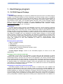
1.1. CLC2006 Support Package
Background
CLC2006 Support Package is a significantly modified and improved version of CLC2000 Support
Package. The CLC2000 software has been developed for Remote Sensing Centre of Hungarian
Institute of Geodesy, Cartography and Remote Sensing (FÖMI), in order to help the implementation of
the European CLC2000 project managed jointly by the European Environment Agency (EEA) and
Joint Research Centre (JRC). The CLC2000 software was also used by many European national
teams, 15 out of 30 participating countries used it for interpreting changes in CLC2000 project.
CLC2006 Support Package is distributed by MLOG Instruments Ltd., Budapest, Hungary
(www.mlog.hu/CLC2006/, fax: 36–1 416 56 50).
Main features
CLC2006 Support Package operates under ArcView environment. ArcView software is designed
primarily for viewing GIS databases with tools for creating maps, menus for handling databases and
graphical editing tools. At the same time, ArcView includes only limited and less effective tools for
creating and filling new polygon databases or modifying existing polygon databases. As a solution,
CLC2006 Support Package under ArcView provides a cheap tool for quick and comfortable editing
and handling of CORINE Land Cover databases. CLC2006 Support Package is a macro package
written in Avenue, ArcView’s own macro language. The software is a supplement to ArcView 3.2/3.3
GIS. Working with CLC2006 Support Package requires a basic knowledge of using ArcView GIS. The
use of the CLC2006 Support Package significantly facilitates updating, change detection, quality
control and correction of land cover databases by means of computer-assisted visual
photointerpretation.
Minimum system requirements
• IBM PC compatible computer,
• 2 GHz processor,
• 512 MB RAM,
• 17" monitor, at least 1024x768 pixel resolution,
• Windows 95/98 or Windows NT/2000/XP operation system,
• ArcView GIS 3.2/3.3 software.
CLC2006 Support Package consists of four interrelated programs, all which can be used
independently.
InterPrepare for the national central team
InterPrepare can be used for the preparation of source files and work directories for change
detection to be carried out with InterChange. For interpreting changes with InterChange program, a
pre-described directory structure has to be built for the interpreters. The directory structure should
contain all files needed for change detection. The source data must have a pre-set record structure.
All the above tasks can be simply solved with InterPrepare. CLC code table editor allows substitution
of standard English CLC nomenclature category names and descriptions with national language
nomenclature in InterChange program. Nomenclature can be edited and can also be extended with
fourth and fifth level categories if required.
InterChange for interpreters of land cover changes
InterChange program provides a tool for the revision of CLC2000 land cover database and
supports the interpretation of land cover changes in order to create the CLC2006 database. The
program provides a convenient and easy-to-use interface for editing polygons in CLC2000 and CLCChange databases, for viewing and modification of polygons’ data and for finding and correction of
errors generated during interpretation and editing. InterChange program was designed specially for
revision of existing land cover databases and interpretation of land cover changes. It is unsuitable for
primary interpretation of satellite images and for building up an independent land cover database. For
4
CLC2006 Support Package
InterChange
these purposes a separate program called InterView was developed, which has been used in the
production of national CLC2000 databases in Croatia, Hungary and Serbia-Montenegro.
InterCheck for checking final databases
InterCheck program serves the checking of revised CLC2000 and CLC-Change map sheets
(working units). InterCheck program has been prepared primarily for supporting the CLC2006
Technical Team, although national central teams might apply it as a tool for final checking of the
completed CLC2006 and CLC-Change databases. InterCheck can be used for checking CLC2006 and
CLC-Change databases in any file format that can be added to ArcView program as a theme (ArcView
shapefile, ARC/INFO coverage, AutoCAD drawing etc.), i.e. not only those that has been prepared
with InterChange.
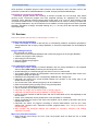
1.2. Services
Red color indicates new services in InterChange 2.0 versus 1.0.
Creating new change-database
• When InterChange is started for the first time, it automatically creates a workspace optimised for
change detection and an empty change database, on which the interpretation can immediately be
started.
Polygon editing functions
The interpreter can easily
• correct errors in the CLC2000 database and create new polygons in the change-database;
• create a new polygon inside a polygon;
• split a polygon into two parts;
• unify two neighbouring polygons;
• delete polygons.
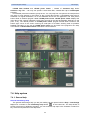
Tools supporting interpretation
• InterChange program displays CLC2000 database and the change database in two separate
View windows (2000, 2006) constantly synchronising their content.
• All data belonging to a selected polygon are shown in the CLC data window.
• The program keeps checking for interpretation rules and warns the interpreter when errors occur
during data editing and data input.
• Edited data are integrated into the corresponding database with a single click.
• Interpreter can change from screen divided between two windows to full screen view of one
window with a single click.
• The environment of the selected polygon(s) can be masked out.
• Data can be edited quickly (usually also by using the keyboard).
• CLC code can be selected from a list box.
• A short comment can be added to polygons.
• Interpreter can modify also CLC2000 code of change polygons.
• Interpreter can add technical change attribute to change polygons.
• Colour of polygon outlines as well as colour and size of code labels can be set separately for the
two windows.
• Centre of the workspace can be positioned to a user specified XY coordinate.
• Actual coordinates and scale of the active View window can be saved to hard disc and can be
reloaded with a click.
• Interpreter can search for polygons according to several characteristics, such as CLC code,
change type, comment, error, supervisor's remark, progress status, area, change probability or
technical change.
• New principle and advanced features are available for importing, searching and fulfilling
supervisor's remarks.
Main error prevention functions
• When selecting and writing in the CLC code, the program does not allow the use of invalid
category codes.
5
CLC2006 Support Package
InterChange
• When editing polygons, the program warns if the created polygon is smaller than the size limit or
is a multipart polygon.
• Non-adjacent polygons cannot be unified.
• An error checking and correcting tool helps to find and correct overlapping or multipart polygons,
selecting polygons below size limit, with shape error, with invalid or zero code.
Information support
• LUCAS land cover and land use data and field photos can be viewed with a single click (if data
available on computer).
• With optional error colouring, the interpreter gets an overview of areas yet to be interpreted, small
polygons, polygons with shape error or without code.
• Code colouring shows interpreted areas with standard international CORINE colour coding.
• Work status colouring allows the interpreter to follow the progress made in change detection, the
size and position of areas yet to be examined.
• Code change colouring helps identification of those changes that are less likely to occur, thus
might need further consideration.
• Code labels of polygons can be switched off/on and can be refreshed.
• A temporary code label can be placed anywhere in the polygon.
• Detailed description of a chosen code can be obtained in a separate window with a single click.
Description might also be available in national language instead of English (the content being the
responsibility of the national project leader).
• With the area measurement tool the area of a planned polygon can be quickly estimated.
• Advanced code, polygon area and code change probability statistics available.
• Thicker polygon outlines as well as larger code labels can be switched on before creating
screenshots for documents and reports.
• InterChange program provides all menus, pop-up texts, information lines and dialog boxes in
English.
• Detailed help, context sensitive help and printable user's guide (all in English) are inherent parts
of the program.
6
CLC2006 Support Package
InterChange
2. First steps
2.1. Project file characteristics
ArcView program handles land cover databases grouped in so called projects. A single project
might contain several independent files such as: raster databases (satellite images, scanned maps),
vector databases (land cover maps, vectorized maps), tables, graphs, layouts, scripts. The project file
links these project elements. Project file has .apr extension. Individual elements remain independent
files regardless of their belonging to the project. Project contains only links according to path and file
name, not the files themselves. However, the project file's text contains in full the links created
between files within ArcView, current settings of ArcView's windows, menus and controls, newly
created dialog boxes and supplementary macros. Thus the individual settings and tools developed
within a project – such as the ones in CLC2006 Support macro packages – are available only when
the given project (or projects created by modifying it) is opened.
Since a project file stores links to files with full path, the project file containing the links should not
be simply moved to another location or computer, not even if all linked files are moved or copied to
that location. If you move a project file this way, the re-located project will search for the linked files at
their original path. If the project is saved to another location and with a different name with File – Save
Project As command, it will use (and mutually overwrite) the linked files together with the original
project. For this reason the empty project (containing one of the CLC2006 Support program)
automatically sets its parameters depending on directory structure upon it's first starting. The empty
CORINE database files are created in the project directory also upon the first start. Therefore
CLC2006 Support Package project files should not be moved after their first opening, as this renders
them useless.
2.2. Installation
• Create a new directory for CLC2006 work at any location on your computer. The directory name is
optional, but is must not exceed 8 characters. Suggested names are e.g.: clc, clc2006 or
corine. Be careful that you use short directory and file names (8+3 usable characters: A-Z, 0-9
and $ _ ~ ^ ! # % & { } ( ) ' @ only) on all directory levels of paths referred to in
CLC2006 work (see example).
• Start install.exe program, which is found in root directory of the source CD (or other data
medium) prepared and delivered by the CLC2006 national central team.
• Select source and destination directory. The program automatically specifies the source directory,
so normally you do not need to modify it. As destination directory select the directory created on the
basis of the first paragraph.
• Click Install button. The install program copies the needed directories and files to the specified
destination directory and deletes their read-only attribute. (The read-only attribute of files on a CD is
always set and it does not change after copying.)
You must not change the name of directories or files. A map sheet (working unit) directory cannot
be moved after the first opening of the included project file.
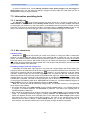
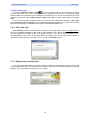
2.3. First opening of a project
Start ArcView program. With File – Open Project command open the interch2.apr project file
in the map sheet directory you wish to work on. If Program directory is incomplete, the program
gives an error message and the start is unsuccessful. In case of successful opening the InterChange
macro package automatically starts. Then from the original source database in the main sheet
directory the program creates CLC2000 database in the Revision subdirectory and loads it to 2000
window. The CLC2000 database is given the same name as the map sheet directory except for an 'r'
ending (r.shp, r.shx and r.dbf ending). The empty change database is created in the Change
subdirectory and is loaded into 2006 window. Files of the change database bear the name of map
sheet directory with a 'c' ending (c.shp, c.shx and c.dbf ending). The original source database
in the map sheet's base directory remains unchanged during interpretation. After creating and loading
7
CLC2006 Support Package
InterChange
databases, InterChange sets theme legends and some other parameters. Then saves the modified
project in a name identical to that of the map sheet directory and sends a message announcing that
the project is ready for starting work on.
With Add theme
button or View – Add theme command further themes (layers) can be
added to the windows. From the appropriate directory load the satellite images you need for
interpretation using this command. You can change the order of layers by dragging and dropping their
names in the windows' left side in the legend stripe. Drag satellite images below the CLC2000 and the
change theme, respectively before starting interpretation. It is recommended that you switch off (with
switch box beside the name) those themes that you do not use at the moment, because redrawing
many layers might significantly slow the program's run. This is applicable especially for satellite
images and other raster files. Save project again with File – Save Project command or Save project
button before starting interpretation.
Project creates the recommended workspace and window settings upon its first start. It is possible,
though impractical to modify it. On later starts the project will always appear with the setting at the last
save.
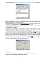
2.4. Customizing the workspace
Before starting to work it is recommended to set monitor resolution to minimum 1024 x 768 pixels
and colour depth to 65 536 colours (Hi Color) minimum. If monitor and video card allow, 1280 x 1024
pixels (or higher) and 16 million colours (True Color) is recommended. When setting the monitor
resolution do not use large fonts or individual font settings, choose small fonts from the font size list.
When using larger fonts it might happen that some texts in the program are not fully seen or not
perfectly readable.
CLC data window can always be seen in front of the other windows. Dragging the header bar you
can move the window. The height of the window – more precisely that of the CLC code list within the
window – can be adjusted with help of the Window height slider in the lower left corner. In case you
wish to use the whole screen during an operation it is recommended that you close CLC data window.
This can be done with Close button, Alt+C keyboard shortcut or the usual Windows close widget in
the upper right corner. When one of View windows are active, F9 keyboard shortcut closes and opens
CLC data window.
Scale of the View windows can be manually set. Optimal scale value depends on the resolution of
satellite images and other ancillary data and the actual interpretation task. The usual recommended
value is between 1:20 000 and 1:40 000. Larger scale might show unnecessary details and slow down
work, while smaller scale might hide some details.
Polygon outline colour, code label colours and font size can be modified in the Settings window. In
most of the cases default yellow and magenta are the most suitable (distinctive) colour.
In the course of work files named delta1.*, delta2.*, ... might appear in mapsheet
directories. These are temporary files created by ArcView during certain operations. These files are
normally automatically deleted when exiting ArcView, however, in certain cases deleting fails. During a
longer work process these temporary files might pile up. Their presence does not cause errors, though
spoil perspicuity of directory content. If disturbed by this, you can delete all delta*.* files when
ArcView is not running. Be careful not to delete any other files!
8
CLC2006 Support Package
InterChange
3. User Interface
3.1. The modified interface
When opening InterChange project window, a modified ArcView interface appears. Only those
menus, buttons, tools and popup menus have been modified, that are associated with 2000 window
or 2006 window. Edit, View and Help menus, button bar, tool bar and popup menu have been
changed. File, Theme, Graphics and Window menus in the View window are left unaltered, these
are the same as the original ArcView menus.
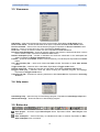
3.2. Edit menu
Undo last edit (Ctrl+Z) – state of polygons is rolled back to that at the beginning of the last editing
operation. Included in the popup menu, too.
Redo last edit (Ctrl+Y) – after performing Undo last edit command, state of polygons is rolled
forward by the last undone editing operation. Included in the popup menu, too.
Union polygons (F4) – unifies two selected adjacent polygons. Can be used only when 2000 window
is active. Equivalent to Union polygons button.
Delete polygons (Del) – deletes selected polygons. Can be used only when 2006 window is active.
Equivalent to Delete polygons button.
Select tool (F2, n) – opens Tool window, and after pressing the n number key (n = 0..9) selects the
appropriate tool. See keyboard template.
Search (Ctrl+S) – opens Search window. You can search for polygons according to several features,
such as CLC code, change type, comment, error, supervisor's remark, progress status or
technical change. Equivalent to Search button.
Find next (F3) – moves to the next polygon that matches search criteria.
Save workspace (F11) – saves momentary co-ordinates and scale of windows. Equivalent to Save
workspace button.
Settings – opens Settings window, in which code label and polygon outline colour code label font
size and save screen parameters can be set. Equivalent to Settings button.
Error checking – starts error checking, which finds and corrects overlapping and multipart polygons
and finds polygons under size limit, polygons with shape error and polygons with invalid or
missing code. Equivalent to Error checking button.
Code statistics – calculates and opens tables containing code statistics of both databases.
Equivalent to Code statistics button.
Import remarks – Imports supervisor's remark database created by InterCheck 2.0. Equivalent to
Import remarks button.
9
CLC2006 Support Package
InterChange
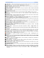
3.3. View menu
Add theme -- adds more themes (layers) to the active window. Equivalent to Add theme button.
Zoom to full extent – shows the full extent of all layers. Equivalent to Zoom to full extent button.
Zoom to selected – zooms to the size of selected polygons. Equivalent to Zoom to selected button.
Zoom in – zooms in on the centre of a view. Equivalent to Zoom in button.
Zoom out – zooms out from the centre of a view. Equivalent to Zoom out button.
Previous zoom (Backspace) - zooms to previous extent of the windows. Used several times it zooms
back to earlier scales. Equivalent to Previous zoom button.
Restore workspace (F12) – window co-ordinates and scale are rolled back to the workspace last
saved. Equivalent to Restore workspace button.
Find XY – opens XY co-ordinate window, to find an arbitrary co-ordinate point. Equivalent to Find XY
button.
CLC data window (F9) – opens and closes CLC data window. Equivalent to CLC data window
button.
Toggle codes (F5) – switches off/on code labels. Equivalent to Toggle codes button.
Rewrite codes (F6) – deletes and rewrites all code labels. Equivalent to Rewrite codes button.
Polygon mask (F7) – switches on/off the mask covering the selected polygon's surroundings.
Equivalent to Polygon mask button.
Colouring off (F8) – switches off colouring switched on with Choice box list. Equivalent to Colouring
off button.
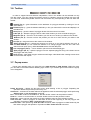
3.4. Help menu
InterChange help – opens the help for InterChange program. Equivalent to InterChange help button.
About InterChange – shows the banner of InterChange program.
3.5. Button bar
Save project – ArcView's original Save Project button. Equivalent to File – Save Project menu
command.
Save workspace – saves momentary co-ordinates and scale of windows. Equivalent to Edit –
Save workspace menu command.
10
CLC2006 Support Package
InterChange
Add theme – adds more themes (layers) to the active window, the same as ArcView's original
Add theme button. Equivalent to View – Add theme menu command.
Import remarks – Imports supervisor's remark database created by InterCheck 2.0. Equivalent to
Edit – import remarks menu command.
Zoom to full extent – shows full extent of all layers. Equivalent to View – Zoom to full extent
menu command.
Zoom to selected – adjusts scale to the size of selected polygons. Equivalent to View – Zoom to
selected menu command.
Zoom in – zooms in on the centre of a view. Equivalent to View – Zoom in menu command.
Zoom out – zooms out from the centre of a view. Equivalent to View – Zoom out menu
command.
Previous zoom – zooms to previous scale. Used several times zooms back to earlier scales.
Equivalent to View – Previous zoom menu command.
Restore workspace – window co-ordinates and scale are rolled back to the workspace last
saved. Equivalent to View – Restore workspace menu command.
Tile windows on/off – changes from screen divided between the two windows to full screen view
and back.
Union polygons – unifies two selected adjacent polygons. Can be used only when 2000 window
is active. Equivalent to Edit – Union polygons menu command.
Delete polygons – deletes selected polygons. Can be used only when 2006 window is active.
Equivalent to Edit – Delete polygons menu command.
CLC data window – opens and closes CLC data window. Equivalent to View – CLC data
window menu command.
Toggle codes – switches off/on code labels. Equivalent to View – Toggle codes menu
command.
Rewrite codes – deletes and rewrites all code labels. Equivalent to View – Rewrite codes menu
command.
Settings – opens Settings window, in which code label and polygon outline colour code label
font size and save screen parameters can be set. Equivalent to Edit – Settings menu command.
Polygon mask – switches on/off the mask covering the selected polygon's surroundings.
Equivalent to View – Polygon mask menu command.
Colouring off – switches off polygon colouring. Equivalent to View – Colouring off menu
command.
Search – You can search for polygons according to several features, such as CLC code, change
type, comment, error, supervisor's remark, progress status or technical change. Equivalent to Edit
– Search menu command.
Find XY – opens XY co-ordinate window, to find an arbitrary co-ordinate point. Equivalent to
View – Find XY menu command.
Code statistics – calculates and opens tables containing code statistics of both databases.
Equivalent to Edit – Code statistics menu command.
>>What is this? << help – context-sensitive help. Gives information on the button, tool or menu
command selected with the pointer.
InterChange help – opens the help for InterChange program. Equivalent to Help – InterChange
help menu command.
Error checking – starts error checking, which finds and corrects overlapping and multipart
polygons and finds polygons under size limit, polygons with shape error (average width under
limit) and polygons with invalid or missing code. Equivalent to Edit – Error checking menu
command.
11
CLC2006 Support Package
InterChange
3.6. Toolbar
In order to support fast and effective interpretation, tools in the toolbar can be selected not only
with the mouse. You can change tool without moving or releasing mouse by striking two keys with
your left hand. Strike F2 keyboard shortcut and the number key corresponding to the tool within the
toolbar.
Identify (F2, 0) – gives information on the attributes of a polygon selected by clicking on it in an
active theme.
Distance (F2, 1) – gives the distance defined by a line you draw with the mouse and displays it in
the status bar.
Area (F2, 2) – gives the area of a polygon drawn with the mouse in hectares.
Label (F2, 3) – labels the polygon with its code at the location you click at inside the polygon.
Magnifier (F2, 4) – Zooms in on the location you click at or on the box you define in the window.
Reducer (F2, 5) – Zooms out from the position you click at or from the box you define in the
window.
Pan (F2, 6) – drags and moves the content of the window.
Select polygon (F2, 7) – selects the polygons you click on or you drag a selection box over. In
the 2006 window you can initiate the creation of a change polygon with this tool. With click
selects remark point (if any). With Ctrl+click selects LUCAS data point.
Cut out polygon (F2, 8) – cuts an island or piece from the selected polygon.
Split polygon (F2, 9) – splits the polygon into two separate polygons along a line drawn across
the polygon with the pointer.
Save screen – Sets wider polygon outlines as well larger code labels befor creating screen shots
for documents and reports.
3.7. Popup menu
Popup menu appears when you right-click in the 2000 window or 2006 window. Within the menu
you can select a command without releasing right mouse. If you release right mouse button the popup
menu disappears.
Delete last point – deletes the last point given while drawing a line or polygon. Repeating the
operation deletes the previous points one by one.
Outline off – switches off the bold outline that appears around the selected polygon while performing
Split polygon or Cut out polygon command.
Pan – moves the content of the window so, that the window centre is at the pointer's location.
Zoom in – zooms in on the window so, that the window centre is at the pointer's location.
Zoom out – zooms out from the window so, that the window centre is at the pointer's location.
Undo last edit – state of polygons is rolled back to that at the beginning of the last polygon edit
operation. Equivalent to Edit – Undo last edit command.
Redo last edit – after performing Undo last edit command, state of polygons is rolled forward by the
last undone polygon edit operation. Equivalent to Edit – Redo last edit command.
12
CLC2006 Support Package
InterChange
4. Interpretation operations
4.1. Editing polygons
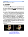
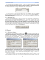
4.1.1. Splitting polygon
With the Split polygon tool
an existing polygon can be cut into two separate parts. First select
the polygon to be split by clicking on with this tool. In case you have not selected any polygon (you
clicked on area not interpreted) or you selected more than one polygon (clicked too close to polygon
borderline) the program sends an error message. A bold outline appears around the selected polygon,
which is especially helpful when splitting large or complex-shaped polygons. Bold outline can be
switched off any time during drawing with popup menu's Outline off command. Instead of – or
together with – bold outline you can also use polygon masking. This tool can be switched on with F7
keyboard shortcut or Polygon mask button after first click (selection) with split tool, but before you
begin to draw.
Position pointer outside the polygon's borderline where you want to start the splitting line. Starting
point and endpoint of splitting line must be outside the polygon, otherwise the operation will be
unsuccessful. Be especially careful that you split the polygon to no more than two parts and that the
parts are connected (not multipart). Define starting point and vertexes with left click and close the line
at the endpoint with double-click.
If you wish to zoom in or out while drawing, use popup menu's Zoom in or Zoom out command. In
case the polygon stretches outside the area seen in the window, use popup menu's Pan command,
which moves the content of the window so, that pointer is located at the centre of the window.
In case you split the polygon into more than two separate parts, the program gives an error
message and the operation will be unsuccessful. In the error message dialog box you can decide
whether to continue or stop trying. If any of the created polygons is under the size limit, you are also
given an error message. This case you can decide whether you wish to execute splitting or not.
If a change area can delineate only on satellite images in 2000 window, select polygon with
Ctrl+click. In this case the bold outline of the selected polygon appears in 2000 window instead of
2006 window. Program gives a warning message: Draw the splitting line in 2000 window! With help of
satellite images for year 2000 you can draw the splitting line in the usual way. The result of the
operation appears once again in 2006 window.
If you used the tool properly the bold polygon outline and/or the mask disappears at the end of
operation. If due to improper use they do not disappear, you can switch mask off with F7 keyboard
shortcut or Polygon mask button. Do not use this button before the splitting operation is finished or
you exited the operation without performing the splitting! If you do so, the bold outline left can be
erased with Rewrite codes command.
The two polygons created by splitting inherit the original polygon's CLC code, comment, remark
and error data. When cutting out a non-island piece from a polygon either Cut out polygon tool and
Split polygon tool can be used. Choose the tool that allows simpler operation with a smaller
possibility of errors.
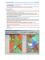
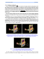
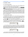
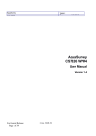
Left: successful polygon splitting
Right: cases of unsuccessful polygon splitting (bringing up an error message) :
2. the splitting line is outside the selected polygon,
3. the splitting line does not entirely cross the selected polygon
4. the selected polygon would be cut into three parts
13
CLC2006 Support Package
InterChange
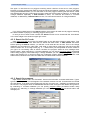
4.1.2. Cutting out polygon
With the Cut out polygon tool
you can create a new polygon inside an existing polygon. First
select the polygon to be cut with a single click of this tool. In case you have not selected any polygon
(you clicked on area not interpreted) or you selected more than one polygon (clicked too close to
polygon borderline) the program sends an error message. A bold outline appears around the selected
polygon, which is helpful especially when splitting large or complex-shaped polygons. Bold outline can
be switched off any time during drawing with popup menu's Outline off command. Instead of – or
together with – bold outline you can also use polygon masking. This tool can be switched on with F7
keyboard shortcut or Polygon mask button after first click (selection) with split tool, but before you
begin to draw.
The new polygon's vertexes are defined with left clicks within the selected polygon's borderline.
Vertexes can be deleted backward one by one with right clicking and choosing Delete last point
command from the popup menu. Polygon drawing is finished with a double-click (the endpoint is a
vertex, too).
If you wish to zoom in or out during drawing use popup menu's Zoom in or Zoom out command. In
case the polygon stretches outside the area seen in the window, use popup menu's Pan command,
which moves the content of the window so, that pointer is located at the centre of the window.
If a change area can delineate only on satellite images in 2000 window, select polygon with
Ctrl+click. In this case the bold outline of the selected polygon appears in 2000 window instead of
2006 window. Program gives a warning message: Draw the splitting line in 2000 window! With help of
satellite images for year 2000 you can draw the splitting line in the usual way. The result of the
operation appears once again in 2006 window.
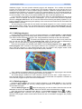
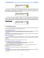
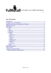
Cases of successful polygon cutting out (naturally only one polygon can be drawn at a time):
The left diagram shows the polygon as drawn with the tool, the right diagram depicts the database
polygon created. 1. cutting out an "island" polygon, 2. cutting out a polygon at borderline
Cases of unsuccessful polygon cutting out (bringing up an error message):
3. The selected polygon would be cut into three parts
4. The new polygon is drawn fully outside the selected polygon
The drawn polygon does not necessarily have to be an "island" (be fully inside the selected
polygon). Only that part of the drawn polygon that is inside the selected one will make up the new
14
CLC2006 Support Package
InterChange
database polygon. The rest (outside selected polygon) will disappear. Thus outside the selected
polygon you can draw the line on a simpler track. The program creates the cut out polygon only if it is
made up of a single part. In case a multipart polygon would be created the program sends an error
message and the drawing is unsuccessful. In the error message dialog box you can decide whether to
continue or stop trying. If the created or remaining polygon is under the size limit, you are also given
an error message. In this case you can decide whether you wish to execute splitting or not.
If you used the tool properly, the bold polygon outline and/or the mask disappears at the end of
operation. If due to improper use they do not disappear, you can switch mask off with F7 keyboard
shortcut or Polygon mask button. Do not use this button before finishing the splitting operation or you
exit the operation without performing the splitting! In this case the bold outline left can be erased with
Rewrite codes command.
The two polygons created with this tool inherit the original polygon's CLC code, comment, remark
and error data. When cutting out a non-island piece from a polygon either Cut out polygon tool and
Split polygon tool can be used. Choose the tool that allows simpler operation with a smaller possibility
of errors.
4.1.3. Unifying polygons
Unifying polygons is possible only in the CLC2000 database, in the 2000 window. In 2006 window
the neighbouring polygons of a change area cannot be unified, not even if their new code is similar.
The reason for this is that each polygon in the change database must keep its old code individually.
tool select two neighbouring polygons you wish to unify. Select the
With the Select polygon
first one with left click, the second with Shift+left click. Same can also be used for deselecting a
polygon. You can also select two polygons by dragging the selection box over them.
Once the two polygons are selected press F4 key, choose Union polygons button
or Edit –
Union polygons menu command. The program sends an error message if you selected any number
other, then two polygons or if the selected polygons are not adjacent. The program draws a bold
outline around the area to be unified if polygons are properly selected.
Then a dialog box appears asking for confirmation. Check whether the right polygons are selected
for unification. On answering Yes the program performs the operation.
The unified polygon inherits CLC code, comment, remark and error data – except merge error –
from the larger polygon. A maximum of two polygons can be unified with one operation. Unification of
more than two polygons requires more than one operation.
4.1.4. Deleting polygon
Polygons can be deleted only from the Change database, in the 2006 window. In the CLC2000
database in 2000 window you can only modify polygon borderline or change CLC code and you
cannot delete a polygon.
select the polygon(s) you wish to delete. Select the first one with
With the Select polygon tool
left click, the others with Shift+left click. Same can also be used for deselecting a polygon.
Once the polygons are selected press Del key, choose Delete polygons button
or Edit –
Delete polygons menu command. The program sends an error message if there is no polygon
selected. The program draws a bold outline around the area to be deleted if polygons are properly
selected.
15
CLC2006 Support Package
InterChange
Then a dialog box appears asking for confirmation. Check carefully whether the polygons selected
for deleting are really the ones you wish to delete. On answering Yes the program performs the
operation.
4.1.5. Undoing operation
Command for the last performed polygon editing operation can be withdrawn before performing a
new operation with Ctrl+Z keyboard shortcut or with Undo last edit command in Edit or popup menu.
The undone operation can be redone – also before performing a new operation – with Ctrl+Y
keyboard shortcut or with Redo last edit command in Edit or popup menu.
4.2. Editing CLC data
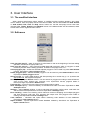
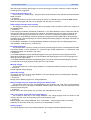
4.2.1. The CLC data window
CLC data window serves viewing, specifying and modifying the data of individual polygons. The
window can be opened with CLC data window button
, the F9 keyboard shortcut or the View –
CLC data window menu command. When a single polygon is selected in the active view window, the
CLC data window displays the data of this polygon. In other cases it appears with the default settings.
In the upper frame of the window you find supervisor remark information of the polygon (if any):
• remark number (selected/all) in polygon;
• show all remarks check box;
• remark done (fulfilled) checkbox;
• Next remark button;
• remark text;
In the lower frame you find polygon data:
• ready (approved) check box for CLC2000 polygons;
• errors of the polygon (if any);
• area of the selected polygon expressed in hectares;
• whole CORINE 1:100 000 land cover nomenclature with short name;
• for polygons in the CLC2000 database CLC2000 code;
• for polygons in the Change database CLC2000 and CLC2006 code,
radio buttons for selecting editable code,
technical change check box;
• button for opening CLC code help;
• list of most frequently used comments;
• text box for displaying and writing in a comment;
• button for clearing the comment text box.
16
CLC2006 Support Package
InterChange
With the Window height slider you can adjust the size of the CLC data window by changing the
height of CLC code list..
Write button writes the contents of the CLC data window into the database while Close button
closes the window.
CLC data window covers a significant part of the screen. In the case of drawing, splitting, unifying
or searching for large polygons or whenever you need a large screen area, it is recommended that
you close this window. This can be done with the Close button, Alt+C keyboard shortcut or the close
widget in the upper right corner of the window. When one of the View windows is active F9 keyboard
shortcut closes or reopens CLC data window.
4.2.2. Specifying the CLC code
With the Select polygon tool
select the polygon whose data you wish to edit. When CLC data
window is opened, the data of the selected polygon appear in it.
Select the line of the right CLC code from the list of category codes. The code number of the
selected category appears in the Code text box. The fastest way of moving in the list to the required
line is to drag and drop the slider of the scroll bar on the right. Detailed description of the selected
code in the CLC code list is available by clicking on Code help button.
You can directly type the code number into Code text box without using the list. After each digit
typed in, the program checks whether there are any existing CLC codes beginning with the given
numbers. If there are, the program jumps to the first matching code and selects it. If you type in a
wrong value, the program selects line Invalid code in the list. If a change polygon is selected, you can
edit both code. Select appropriate radio button to enable desired code text box. If technical change
check box is selected, you can't select 2000 radio button or specify CLC2000 code, because in this
case CLC2000 and CLC2006 codes must be identical!
4.2.3. Application of comments
During interpretation you might need to add questions or notes to a polygon then search for them.
The Comment text box in CLC data window serves this purpose. The comment added to a polygon
appears in this text box when the given polygon is selected.
17
CLC2006 Support Package
InterChange
The comment must not exceed 255 characters. To add a new comment or to modify an existing
one you can select from the drop-down list of most common comments or type your comment in the
text box. The comment selected from the drop-down list can be modified or completed in the text box.
The Delete comment button on the right side of the list clears Comment text box.
You can find the list of most commonly used comment in the comment.txt file in Program
directory. The list can be modified with help of any text editor program, such as Windows Notepad. In
the text each paragraph forms a separate comment. First two comments (paragraphs) in the text must
not be modified at any case!
4.2.4. Writing the data
Content of the CLC data window is written into the land cover database with the Write button or
Alt+W keyboard shortcut (if CLC data window is active). The program checks the data and the
selected polygon before writing in and if finds any error, it sends an error message. If data matches
the criteria, program writes data into the data table. The outline of the selected polygon flashes a few
times during this procedure so you can check whether data are written into the right polygon. After
writing in the data, the data table is saved into the corresponding .dbf file. The polygon is deselected
and the CLC data window assumes default settings. In case you wish to continue editing the polygon
data you have to select it again with the Select polygon tool.
4.3. Search
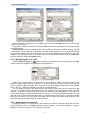
4.3.1. The Search window
Search window can be opened with the Search button
, the Search command in Edit menu
or the Ctrl+F keyboard shortcut. On the left side of the Search window you find Find what? radio
button group, which specifies the search target. Further criteria (or the text searched after) can be
specified for some of the searches. By searching in CLC2000 database you can specify progress
status (unchecked and/or ready polygons), by searching in Change database you can specify change
type (technical and/or real changes) too. After specifying criteria start search with the Search button.
Next the program finds, selects and enlarges the first polygon matching the search criteria. In order
to be easily identified the outline of the polygon flashes. The same time as the polygon is selected, the
Find xxx window opens. In the header of the window xxx is replaced by the search target. The Find
xxx window is always in front of all other windows, in the foremost position. First row of the window
shows search criteria. Below that the serial number of recently shown polygon / number of all
polygons found can be seen.
If you click on Next button, the next polygon found appears in the window. By clicking on Next
button repeatedly the program goes round all polygons found, so after the last polygon it steps to the
18
CLC2006 Support Package
InterChange
first again. In case there are no polygons matching search criteria or there are no more polygons,
because you have changed their data the program sends the following message: Could not find! After
closing the Find xxx window you can still move to the next polygon matching the last search criteria
with F3 keyboard shortcut. InterChange program preserves the last search criteria for CLC2000 and
Change database separately. If 2000 window is active, F3 continues last search in CLC2000
database; or alternatively if 2006 window is active, F3 continues last search in Change database.
If you click on Mask button in the Search window, the program will mask out all polygons matching
the criteria instead of jumping on matching polygons one by one.
In case you do not wish to start a search the Search window can be closed with the Close button
or the close widget in the window's upper right corner.
4.3.2. Search for CLC code
Open Search window and in the Find what? frame on the left select Category radio button. Type
the wanted code into the code 2000 text box beside the radio button. If 2006 window was active
before opening the Search window, you will find a code 2006 text box as well. Thus in the change
database you can search for code 2000, code 2006 or code change (code pair). Not only three-digit
codes, but also one- or two-digit codes (eg. 11 –- Urban fabric) can be specified as search criteria. If
you type in a non-existing code as search condition, the program sends an error message when
starting search. When searching in CLC2000 database you can specify progress status (unchecked
and/or ready polygons), when searching in Change database you can specify change type (technical
and/or real changes) too. If technical check box is selected, program deletes the content of the code
2000 text box, because in this case CLC2000 and CLC2006 codes must be identical!
4.3.3. Search for comment
Open Search window and in the Find what? frame on the left select Comment radio button. Type a
typical expression, word or word-fragment of the wanted comment into the Comment text box beside
the radio button. If you wish to find all polygons with any comment, type * (asterisk) as wanted text into
the text box. The program does not differentiate between lower and upper case letters during search.
By searching in CLC2000 database you can specify progress status (unchecked and/or ready
polygons), by searching in Change database you can specify change type (technical and/or real
changes) too.
19
CLC2006 Support Package
InterChange
4.3.4. Search for data errors
Open Search window and in the Find what? frame on the left select Errors radio button. Beside this
radio button you find two check boxes to refine search criteria. If you select size errors check box, the
program searches for polygons under the given size limit. (When creating change polygons or giving a
code to them the program sends a warning message if the polygon is below size limit. If you still
decide to keep these polygons, they will not be displayed during size error search.) If you select code
and merge errors check box, the program searches for polygons with invalid category codes, and for
neighbouring polygons with the same category code (only in CLC2000 database). On selecting both
check boxes the program searches for both error types. If you fail to select at least one check box, the
program sends an error message. By searching in CLC2000 database you can specify progress
status (unchecked and/or ready polygons), by searching in Change database you can specify change
type (technical and/or real changes) too.
Searching for polygon errors is recommended primarily after error checking, in order to search for
errors found by the error checking. There is no point in searching for size error before error checking,
because size and shape errors are written to the polygons' data records only during this procedure.
Code error can be searched for any time, because code error is written to the new polygon's data
record at the time of creation.
4.3.5. Search for remark
Search for remarks is needed only during the correction of mistakes revealed by quality control.
Open Search window and in the Find what? frame on the left select Remark radio button. Type a
typical expression, word or word-fragment of the wanted remark into the Remark text box beside the
radio button. If you wish to find all polygons with any remark, type * (asterisk) as wanted text into the
text box. The program does not differentiate between lower and upper case letters during search. After
specifying criteria start search with the Search or Mask button.
If remark theme is absent in the active view window, program displays a warning message.
Othervise finds and selects the first remark point matching the search criteria and displays remark text
in CLC data window. If the found remark point is located in a polygon, program selects polygon too,
and displays its data in the CLC data window. According to the setting of show all check box in CLC
data window, search occurs among all remark points or only among the unchecked remark points.
4.3.6. Search for progress status
All searches within CLC2000 database can be restricted to polygons already checked or polygons
not examined yet. To carry out these select the relevant one from Progress status check boxes. If you
select both, the program searches among all polygons in CLC2000 database. If you miss selecting at
least one, the program sends an error message.
20
CLC2006 Support Package
InterChange
You can search for all checked or all not examined polygons too, regardless of their other
characteristics. For this open Search window and in the Find what? frame on the left select Category
radio button. Don't type any code into the code 2000 text box beside the radio button. When clicking at
Search button, program sends a warning, and begins the search for polygons with specified progress
status flag.
4.3.7. Search for change type
All searches within Change database can be restricted to technical change polygons or real
change polygons. To carry out these select the relevant one from Change type check boxes. If you
select both, the program searches among all polygons in Change database. If you miss selecting at
least one, the program sends an error message.
You can search for all technical polygons too, regardless of their other characteristics. For this
open Search window and in the Find what? frame on the left select Category radio button. Don't type
any code into the code text boxes beside the radio button. When clicking at Search button, program
sends a warning, and begins the search for technical change polygons.
4.3.8. Find XY co-ordinate
With the Find XY tool
an arbitrary co-ordinate point can be find. On clicking this button the XY
co-ordinate window opens. In this window you can type in the co-ordinates you are looking for.
Clicking the Find button brings the given co-ordinates to the centre of the window and labels the
location with a cross. The scale of the window does not change.
If the point specified in the XY co-ordinate window falls outside the area of the map sheet you are
working on, the program sends an error message.
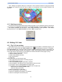
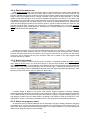
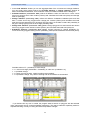
4.3.9. Code statistics
Select Code statistics button
or the Code statistics command in Edit menu. As a result,
the program calculates and displays four statistics and summary dialog. The appropriate .dbf files
can be found in the mapsheet directory.
21
CLC2006 Support Package
InterChange
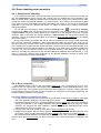
• In the Code statistics window you can see aggregate data of the CLC2000 and Change database.
You can simply select sorting method for CLC2000 statistics or Change statistics. Refresh all
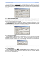
button recalculates all statistics, Close all button closes four statistical tables and the dialog too.
• CLC2000 statistics (stat2000.dbf) collects all different codes and lists them. It also counts
how many polygons each code contains (Pieces) and calculates their total area (Area) and average
area too (Average).
• Change statistics (statchng.dbf) collects all different Code2000–Code2006 pairs and lists
them. It counts how many polygons each change pair contains (Pieces) and calculates their total
area (Area) and average area too (Average).The last column of the table contains the probability of
the given change type (P) built in the change probability table.
• Change area statistics (statarea.dbf) gathers change polygons into area intervals and shows
how many polygons each interval contains (Pieces) and calculates their total area (Area) too.
• Probability statistics (statprob.dbf) gathers change polygons by change probability (P),
counts how many polygons belong to each probability (Pieces) and calculates their total area (Area).
Possible values of P – probability of code change:
• 0 = technical change (Code2000 = Code2006), or code error (Code2000 = 0);
• 1 = probable change;
• 2 = rarely occurring change, careful checking recommended;
• 3 = improbable change, very careful checking and documentation recommended.
If you double-click any row in a table, the program starts a search for polygons with the selected
code, change type area or change probability respectively. This search method is especially useful for
repeated checking of rarely occurring and almost improbable changes.
22
CLC2006 Support Package
InterChange
4.4. Error checking and correction
4.4.1. Starting error checking
If you follow the instructions of the printed user's guide and the pieces of advice in this help and
you use InterChange program properly and carefully, then the created land cover database is not
likely to contain errors. However, programs have an efficient error finding and correcting tool in order
to filter the results of accidental mistakes. You should perform error checking and correction at least
once, when you finish interpretation and before submitting your results. If you are not an experienced
interpreter or you work on a difficult map sheet, it is useful to perform error checking a few times
during interpretation.
You can start error checking by clicking the Error checking button
or select Error checking
command in the Edit menu. The program asks for confirmation. The operation starts on clicking Yes.
If 2000 window was active before starting error checking, then the program will check CLC2000
database, while it will check the change database, if 2006 window was active before starting the
operation. You can find detailed description of the individual error checking operations in the chapter
Special information.
During error checking a progress bar can be seen at the bottom of the screen. While performing
the most time consuming operations a Stop button appears beside the progress bar, thus you can
stop error checking. The Stop button does not appear during shorter operations. Upon completing the
error checking the program lists the number and type of errors found in an information window. If no
error has been found, the program reports it in a dialog box. The result of error checking is written into
a text file, too. You can find the text file in the map sheet directory under error_r.log name in
case error checking was performed for the CLC2000 (Revision) database and under error_c.log
name in case error checking was performed for the Change database. Results of further error
checkings are added to the end of these files.
4.4.2. Error correction
Open Search window and find the next polygon with error . After correcting the error (or even
without it) you can jump to the next polygon with the Next button of the Find next window, or by
pressing the F3 key. The program jumps round the matching polygons cyclically, meaning that after
the last polygon it jumps to the first (not yet corrected) one. If there are no matching polygons left, the
program sends a message: Could not find!
Correction method of individual error types:
• In case of those polygons below size limit that you still wish to keep write in category code again
and in the appearing dialog box choose keeping the polygon.
• Unneeded small polygons in the CLC2000 database must be unified with one of their neighbours
during the correction. In the change database simply delete unneeded small polygons. Those
extremely tiny polygons that were created by mistake along polygon borderlines might not be
visible unless you zoom in on them a lot.
• Polygons with code error should be corrected by giving a category code to them.
• Neighbouring polygons with the same category code in the CLC2000 database have the error
type merge. These polygon pairs should be either unified or the code of one of them changed.
The operations above delete the corresponding bit from the error code, and the error type text from
the error field. With error colouring you get an overview of the number and position of polygons with
error.
23
CLC2006 Support Package
InterChange
5. The interpretation process
5.1. General advice
When working with smaller performance computer on a map sheet containing a lot of polygons,
some editing and search operations might need significant time. Be careful that in the meantime you
do not strike a further key or start a new operation. Always wait until the program fully performs the
operation started and its result appears on the screen!
The program does not perform an automatic save after polygon editing operations, because that
would make the use of undo command impossible. Periodically save your project while editing it!
For maximum data safety it is recommended frequently backup the CLC2000 and change
databases from Revision and Change subdirectory of each map sheet directory.
5.2. Saving workspace
In case you wish to return later to a given part of the map sheet, you can save the temporary view
, Edit – Save workspace
(co-ordinates and scale) of the window with Save workspace button
menu command or F11 keyboard shortcut. After this you can move or zoom on the map sheet as you
wish. When you want to return to the workspace saved, click Restore workspace button
, select
View – Restore workspace menu command or use F12 keyboard shortcut to restore the workspace
(area and scale) you last saved.
The file containing data of the workspace is saved to the given map sheet's working directory. Thus
a separate workspace can be saved for each map sheet and can be restored any time later.
5.3. Order of operations
Revision and correction of CLC2000 database
The revision of CLC2000 database, which is found in the 2000 window, should be done before
beginning to interpret changes. For revision always use satellite images in the Revision directory
taken around 2000! Maximise 2000 window with the Tile windows on/off button
while revising
the database. After you have finished revision start error checking and correct errors found. Repeat
this procedure until no more errors are found in CLC2000 database.
Interpreting changes, creating change database
After finishing the revision of CLC2000 database, divide screen between 2000 window and 2006
window with Tile windows on/off button and perform change interpretation. Systematically examine
the whole area, all the polygons of the map sheet whether they contain changes. If more satellite
images are available for the year 2006, check for changes on all of them. Check whether the change
matches interpretation criteria.
Before beginning to create change polygons in a given area, check the affected CLC2000 polygons
whether they need further correction. If you classify the affected polygons as correct, create the
change polygons on the basis of satellite images in the 2006 window. Creation of change polygon
consists of the following steps:
1. take over CLC2000 polygon containing a change into the Change database
2. cut out change area from the polygon taken over;
3. delete the unchanged part of polygon taken over;
4. specify the new code of remaining change polygon.
Program InterChange facilitates these operation significantly. A given CLC2000 polygon might of
course contain more than one change area. If this is the case, steps 2 and 4 must be completed for all
change areas. To monitor the status of the work you can give a “ready” status to a CLC2000 polygon if
you have examined it, and all its changes have been delineated.
It is not recommended to carry out corrections in the CLC2000 database on the given area once
you interpreted changes. If however later you happen to find mistakes in a CLC2000 polygon that
already has a change polygon on its area, the program might delete change polygons depending on
the type of correction made. In this case you have to create the change polygons again. If you modify
CLC2000 database while already working on change database, you have to repeat error checking and
correction on them.
24
CLC2006 Support Package
InterChange
Switching on status colouring you can check the progress made in change detection. Perform error
checking and correct errors in the change database after you have finished change detection. Repeat
this as long as the program finds any errors. Even after this it is recommended to check each change
polygon once more. Pay special attention to checking and documentation of rarely occurring and
improbable changes!
Submission and control
As interpreter finished interpretation he/she have to submit the .shp, .shx and .dbf files from
Revision and Change subdirectories of each interpreted map sheet as a result. Central team
controls databases and documents the errors and mistakes. If the original interpreter corrects the
mistakes, he or she must read the remarks of the supervisor and implement corrections.
5.4. Revision of CLC2000 database
The following cases might occur during the revision of CLC2000 database:
• The polygon has wrong code. Modify code in CLC data window.
• A polygon must be cut into pieces and be re-coded. Use Split polygon or Cut out polygon tool to
perform the operation.
• You have to unify more polygons into one. Use Union polygons command.
• Polygon borderline has to be modified. In 2000 window there is no tool for deleting and re-drawing
polygons. Borderline modification must be carried out with the Split polygon and the Union polygons
tool. However, with these tools only one piece of area can be "moved" from one polygon to the other
at a time. If you have to modify two polygons' borderline at more points, a more effective method is
unifying the polygons first then splitting them along the right borderline again. This case though you
have to specify again the smaller polygon's code, because it is changed during unification.
5.5. Interpreting changes
If it is not obvious at first sight whether a change area is large enough to be interpreted, measure
its area with the Area tool before interpreting it. While using this tool you also get further pieces of
advice on the steps of interpretation. In case you interpret a narrow patch, be careful to check width
with the Distance tool.
In the 2006 window click with the Select polygon tool to the area where you observed a change
or to the polygon you examined. A dialog window appears asking a question: Take over selected
polygon to change database? There are four choices:
• Yes, take over. – The program copies the CLC2000 polygon containing a change into the change
database. Then you can cut the area of actual land cover change from this polygon.
• Yes, take over and classify as ready. – The program takes over the polygon to the change
database and writes in the "ready" classification to the CLC2000 polygon's data record. During the
creation of change database you have the possibility to classify as ready those CLC2000 polygons
that you have examined. This option should be chosen only if the whole area of the polygon has
been thoroughly examined. It is not recommended to use it in case of large polygons.
• No, only classify as ready. – The program writes in "ready" classification into the CLC2000
polygon's data record. The option should be chosen only if you have examined the whole area of
the polygon and there are definitely no or no more change areas in it. It is recommended to use in
two cases: a) small polygons without any changes; b) large polygons containing several change
areas, after all changes have been interpreted and the whole polygon is examined again.
• No, only delete ready classification. – Choose this option if you classified a polygon ready by
mistake or if you have doubts about the polygon and you find necessary to check it later.
Use Split polygon or Cut out polygon tool for splitting up polygons taken over to change database
in order to create change polygons. While performing splitting consider warnings on polygons under
size limit created. Always delete unneeded pieces of the split polygon (areas that have not changed)
with Delete polygons tool and keep only change areas! Specify the change polygon's new code in
CLC data window.
25
CLC2006 Support Package
InterChange
6. Quality control
6.1. The control procedure
As a result of interpretation you have to submit the .shp, .shx and .dbf files from the
Revision and the Change subdirectory. A further technical control of these databases with a
computer and a thematic control by another expert is highly recommended.
For thematic control, a slightly different program called InterCheck – part of CLC2006 Support
Package – should be used. The controlling expert (supervisor) can put down his/her notes on
mistakes and correction suggestions for the interpreter/corrector in the Remark database created by
InterCheck program. During thematic control the remarks referring to polygons or to individual points
of the map sheet are written in this database.
Using CLC2006 Support Package, thematic control and correction based on supervisor’s remarks
is simple to carry out and also to repeat several times during interpretation procedure. In case the
interpretation made with InterChange and thematic control is made by InterCheck the same single
directory structure and files can be used throughout the production procedure. Copying or moving of
files is not necessary. The two actions – interpretation and control – only reads but never overwrites
each other’s data. Naturally, interpreter and supervisor should never work simultaneously on a single
map sheet. In order to ensure maximum security it is highly recommended to regularly make backup
saves of CLC2000 and change data files (containing the results of work) from each map sheet’s
Revision and Change directory.
6.2. Correction after control
During thematic control the supervisor creates two ArcView shapefile format point databases with
help of InterCheck program and writes his or her remarks and recommendations into text fields
belonging to each point. Files Remark_r.shp, .dbf, .shx created in Revision subdirectory of
the concerned map sheet contains remarks on CLC2000 database, while files Remark_c.shp,
.dbf, .shx in Change subdirectory contain remarks on the change database.
In order to correct them, remarks can be imported to the corresponding view window by clicking on
Import remarks
button or choosing the Edit – Import remarks menu command. The two
remark databases can be imported separately as in certain phases of the work only either CLC2000 or
the change datbase is under supervisor control, creating only one database at a time.
tool.
Single remark points can be selected by clicking on them with the Select polygon
Selected point is marked by its yellow colour meanwhile the remark’s text is displayed in remark text
field of the CLC data window.
In CLC2000 database all remark point necessarily fall into a polygon’s area. In change database
however, remark point might also be out of any polygon’s area, for example in a change area that the
interpreter missed to delineate. If selected point falls into a polygon’s area, the program selects the
polygon itself as well, also displaying its data in the CLC data window. If a polygon contains a remark,
its text is displayed when selecting the polygon the same way as if the point itself would have been
selected. One polygon might contain more than one remark point. When selecting such polygon only
the number of included remarks is displayed in the remark textbox.
You can view the text of these remark points jumping along the points one by one by clicking on
the Next remark button in upper right hand corner of the text field. During this the serial number of
currently selected point / total number of points in the polygon is displayed beside the Remark label.
26
CLC2006 Support Package
InterChange
Processing and fulfilling the action requested in the remark can be registered by clicking on the
done checkbox in CLC data window. The program immediately writes done attribute to the point’s data
record and the colour of the point turns from red to green. The done status can be deleted again with
help of the checkbox after selecting such point again.
In case you want only those remarks to appear on the screen that still wait to be fulfilled and the
processed ones to disappear, switch off by clicking the show all checkbox. In switched off status of
show all checkbox only red remark points appear on the screen, the Next remark button jumps to the
next unchecked point within the polygon and search tool finds also only the unchecked points when
searching for remarks.
6.3. Handling remarks
This list of most frequently used remarks describes in which cases the quality supervisor uses a
given remark and how should it be handled during correction.
Questionable code, check it.
This remark used only in the CLC2000 database. The code cannot be specified on the basis of
available satellite images. More information is needed for deciding which code to use.
• Correction:
Check by fieldwork, ask for information by phone or specify the code on the basis of other information.
Additional information should always be documented.
Wrong code, suggestion:
This remark used only in the CLC2000 database. The code given by the interpreter is definitely
incorrect on the basis of available satellite images. After the colon the proposed correct code should
be given.
• Correction:
Modify code or document clearly why you think your code is correct.
Unify polygon with neighbour, whose code is:
This remark used only in the CLC2000 database. Polygon should be unified because
• it is smaller than the size limit and there is no reason to keep it;
• its land cover does not differ from its neighbour's.
In case the polygon has more than one neighbour (so it is not an island polygon) the code of the
polygon to be unified should be given after the colon.
• Correction:
Unify polygon with the specified neighbour with the Union polygons tool.
Split polygon.
The polygon consists of two or more areas with different category codes. Remark may also include
the recommended way of splitting and the code of polygons to be created.
• Correction:
27
CLC2006 Support Package
InterChange
Split the polygon with the Split polygon or the Cut out polygon tool then modify the codes of the parts
according to the suggestion.
From inside the polygon cut:
Used in case of – usually large – polygons that include small land cover patches that the interpreter
failed to outline.
• Correction:
The specified locations can be found with help of the XY co-ordinate button in the CLC data window.
Draw the new polygon with the Cut out polygon tool and give CLC code to it.
Draw polygon's border more precisely.
The polygon borderline is inaccurate, does not properly match the patch of land cover category in
the satellite image.
• Correction:
Correct polygon borderline. Borderline modification in CLC2000 database must be carried out with the
Split polygon and the Union polygons tool. However, with these tools only one piece of area can be
"moved" from one polygon to the other at a time. If you have to modify two polygons' borderline at
more points, a more effective method is unifying the polygons first then splitting them along the right
borderline again. This case though you have to specify the smaller polygon's code again, because it is
lost during unification.
For borderline modification in Change database delete then polygon with the Delete polygons tool
and recreate it, finally give CLC code to them.
Re-interpret the area.
This remark refers to an area, usually covered by several polygons, that is misinterpreted and there
are several border or code mistakes in it. Remark might include explanation or if required a more
detailed description can be read in the report.
• Correction:
In CLC2000 database unify the specified polygons in the given area with Union polygons tool then
interpret the area again according to recommendation with Split polygon tool or Cut out polygon tool,
finally give CLC code to them.
In CLC2006 database delete the specified polygons in the given area with Delete polygons tool then
re-create the the change polygons, finally give CLC code to them.
Missing change.
This remark used only in the change database. The interpreter failed to outline the change area.
• Correction:
Create required change polygon.
Impossible change.
This remark used only in the change database. The code change given by the interpreter is definitely
improbable (e.g. 111 –-> 211).
• Correction:
Modify code or Delete polygon from change database.
Wrong change code pair. Proposed change from 2000 to 2006:
This remark is used only in the change database. The old and/or new code given by the interpreter
is definitely incorrect on the basis of available satellite images. After the colon the proposed correct
code pair should be given.
• Correction:
Modify code or document clearly why you think your interpretation is correct.
Not a real change. Proposed code in both dates is:
This remark is used only in the change database. The change polygon does not outline a real
change. After the colon the proposed correct code should be given.
• Correction:
Delete polygon from change database, and – if necessary – modify original code in CLC2000
database; or document clearly why you think your interpretation is correct.
Delete polygon:
This remark appears only in the change database. The polygon should be deleted because
28
CLC2006 Support Package
InterChange
• it is smaller than the size limit and there is no reason to keep it;
• it does not outline a real change;
• Correction:
Delete polygon with the Delete polygons tool.
Technical change.
This remark used only in the change database. The change area should be marked as technical
change.
• Correction:
Mark change area as technical change.
Further remarks are logical combinations of the ones listed above.
29
CLC2006 Support Package
InterChange
7. Information support
7.1. Code labels
7.1.1. Handling code labels
Switching off and on code labels
In areas with a lot of relatively small polygons the code labels might disturb the interpreter during
interpretation. In these cases code labels can be switched off on the screen with Toggle codes button
, the Toggle codes command in the View menu or with the F5 keyboard shortcut. Repeating the
command, code labels are switched on again. This command does not refresh the content and
position of labels, so they will appear at the same position as before switching off.
Manual code labelling
ArcView places code labels in the geometric centre of the polygon. Therefore sometimes it is
difficult to find the code label of polygons that are large, have complicated shape or concentric
position. The labels might fall outside the view as well. In order to solve this problem you can manually
. Click at the required location
place code labels on any part of the polygon. Choose Label tool
inside the polygon and its code appears at that location. This way you can place several code labels
within a polygon. These manual labels stay there when you switch labels off and on, but they
disappear after you perform any polygon editing operation or refreshed code labels. Label tool works
in 2000 window with CLC2000 database, in 2006 window with Change database.
Rewriting code labels
After significant zooming in or out code labels might appear outside the polygon they belong to.
This case you can delete and rewrite them with the Rewrite codes button
, the Rewrite codes
command in the View menu or the F6 keyboard shortcut. This operation is automatically performed
each time after you edit polygons or you write in polygon data to the table.
7.1.2. Setting label properties
The optimal font size of code labels depends on the size, quality and resolution of the monitor used
during interpretation. Sometimes you might need to change the colour of code labels and polygon
outlines because of significant differences within satellite images.
or the Edit – Settings menu
You can open Settings window with the Settings button
command. When opened, the window shows settings of the CLC2000 and Change themes. The code
label and polygon outline colours and the code label font size can be modified with radio buttons as
well. In Save screen panel polygon outline width and code label font size can be set for creating
screen shots for documents and reports. Modify button performs the selected modifications. Cancel
button closes the Settings window without performing modifications.
Colours should be chosen so that the lines stand out best in front of the area just being interpreted.
This depends very much on the quality and settings of the monitor used. In most of the cases default
30
CLC2006 Support Package
InterChange
yellow and magenta are the most suitable. It is recommended to set different colours for CLC2000 and
change database.
7.2. Colourings and masks
7.2.1. Colouring of polygons
On the right side of the toolbar you find Polygon colouring (labelled as Choice Box ) drop-down
list, which allows you to switch on polygon colourings. The colouring can be switched off with selecting
the Colouring off line in the list, the Colouring off button
command or the F8 keyboard shortcut.
, the View – Colouring off menu
Colouring polygons by errors
Polygons appear in different colours according to their error type: invalid (missing) code, size error
and both errors. During error correction you get an overview of the position and number of polygons
with error. Code errors are up-to-date, while size and shape errors are up-to-date only right after
running error checking.
Colouring polygons by CLC codes
One of the applications of the finished database is producing maps. This colouring shows polygons
according to the internationally set CLC colour coding. Selecting this colouring the polygons appear in
colours specified for the third level (three digit) CORINE categories, zero coded polygons are white.
Before switching this colouring on it is recommended to switch off the visibility of background satellite
images.
Colouring CLC2000 polygons by status
While creating the change database there is a possibility of classifying CLC2000 polygons as
ready, if the whole area of the polygon is checked. Status colouring shows these polygons in light
grey, while polygons yet to be checked remain transparent. Thus you can check how much progress
you have made in the change detection and where there are areas yet to be worked.
Colouring change polygons by probability of change
To each change type (pair of old code – new code) belongs a value indicating the probability of that
land cover change. Change colouring shows polygons with code error (zero code) and technical
change polygons in red, area of probable changes in grey, area of rarely occurring changes in yellow
and the area of improbable changes in magenta. This colouring draws attention to areas of less
probable changes, which should be checked and documented with special care.
7.2.2. Polygon mask
A black mask around selected polygons can be switched on or off in the active View window with
the Polygon mask button
, the View – Polygon mask menu command or the F7 keyboard
shortcut. When the mask is switched on, only the selected polygons are visible, the rest of the view is
black.
31
CLC2006 Support Package
InterChange
Polygon mask is especially useful in avoiding mistakes when splitting or cutting out a polygon. It is
also a helpful tool when you examine polygons with complicated shape and you want to eliminate the
disturbing presence of surrounding polygons.
7.2.3. Searching with help of mask
Set the search conditions in Search window then click Mask button. This case the program will set
off matching polygons with a black mask on their environment instead of jumping on them one by one.
You can move or change scale on the masked area at will. If you do not need the mask any more you
can switch it off with the Polygon mask button
the F7 keyboard shortcut.
, the View – Polygon mask menu command or
Searching with mask is especially useful when looking for polygons with some similar features. It
can also be helpful when at an advanced state of work you are looking for polygons you still have
something to do with. With this method you can find polygons with:
• the same category code or change type;
• any comment or remark;
• a given key word (e.g. "field checking") in the comment or remark text;
• a given error type.
7.2.4. Save screen tool
Compilation or illustration of reports, documents, computer demonstrations might make necessary
creating screenshots from certain parts of the map sheet. Due to resizing thin polygon boundaries and
tiny code labels are very often hardly if at all visible and readable on these saved images. In case you
tool. As a
want to make such screenshot for documentation purposes select the Save screen
result, the program increases polygon boundary width and code label font size. These parameters can
be freely modified in the Settings window.
Modified settings are kept even if you use the Label, the Magnifier, the Reducer or the Pan tools,
with help of which you can adjust the view to be saved. If the view is adjusted, save it to the clipboard
by pushing Ctlr+PrintScreen keys. Open an image editor or word processor program, paste image
into a document and save to disc.
32
CLC2006 Support Package
InterChange
In order to continue work, choose Identify, Distance, Area, Select polygon, Cut out polygon or
Split polygon tool. This will reset the settings: polygon boundary width and code label font size is
readjusted according to original settings.
7.3. Information providing tools
7.3.1. Identify tool
The Identify tool
in the toolbar provides the same service as in ArcView. Clicking with it in
2000 window or 2006 window opens Identity results window, which provides detailed information
on the polygon you clicked on in the active theme. If the desired theme is not active, activate it with a
sigle click on its name in the windows' left side in the legend stripe. In Identity results window on the
left you can read the name of the polygon, while on the right all data belonging to it in the table.
7.3.2. Size check tools
Checking width
serves the checking of a land cover patch's or a polygon's width, to make sure
Distance tool
whether it is above width limit. Begin the line to be measured with a single click. As you move the
pointer, the distance between start point and the pointers position in metres can be seen in the status
bar at the bottom of the screen. With further clicks you can define the total length of a broken line as
well. Finish length measurement with a double click. The length of the last section and the line's total
length remains visible in the status bar.
Estimating polygon area and change area
Interpreting a change area might require a long time and it might happen that during editing the
polygon proves to be small and it ends up that it should not have been interpreted. For this reason it is
whether it is worth beginning at all the editing
useful first to examine with the quick Area tool
operation. Outline roughly the area of the polygon you wish to create with the tool. Vertexes can be
drawn with left mouse click and last points can be deleted with right click. Popup menu commands are
available here, too. Upon closing line with a double-click, in the status bar you can read the area of the
outlined part in hectares. The area of existing polygons can be found out without drawing if you click
on the polygon with Ctrl key held down. Ctrl+click method works for CLC2000 database polygons in
2000 window and only for change database polygons in 2006 window.
Area tool can also be used for estimating change areas. To compare the area of a changed land
cover patch in both window,
• first outline the patch in the 2000 window on the CLC2000 satellite image – or if it already exists as
a polygon in CLC2000 database, use Ctrl+click for selection. The area of the original patch in
hectares appears in status bar.
• Next outline the changed area of the land cover patch in the 2006 window on the CLC2006 satellite
image – or if it already exists as a polygon in Change database, use Ctrl+click for selection. In the
status bar appears the area of the changed patch. At the same time Area change window opens
and shows the area of original patch (first measure), the area of the changed patch (second
measure) and the size of change. In Area change window you can see the change type too. In
Hints text box you find short instructions on how the given change should be interpreted.
33
CLC2006 Support Package
InterChange
Help button (Alt+H) opens the corresponding help topic. The window can be closed with two
buttons. The default button out of the two is always the one, whose use is the most likely according to
the Hint' s text. Instead of clicking on it, the default button can be operated quicker with striking the
Enter key. Both buttons have a keyboard shortcut, too.
• Use Interpret button (Alt+I) if you have to interpret the change area according to the Hints text. On
selecting this button 2006 window and Select polygon tool will become active.
• With Close button (Alt+C) the program restores the state before the window was opened. Last used
window and Area tool will become active.
7.3.3. LUCAS data window
When opening a map sheet for the first time program checks if there are LUCAS00.shp and/or
LUCAS06.shp files in the LUCAS directory found on the same directory level as map sheet
directories. If LUCAS data are found they are loaded into the corresponding view window.
Data belonging to LUCAS points might serve as useful ancillary data during change mapping. The
. In case the
full data content belonging to a LUCAS point can be displayed with the Identify tool
information found in LUCAS data window strongly contradict the satellite image, check this additional
information on the LUCAS point. High observation distance, low GPS accuracy and non-field
observation might be the cause of disagreement between LUCAS information and the satellite image.
However, usually only certain data are needed during change mapping. These can be viewed if you
tool. If LUCAS data
select the required LUCAS point by Ctrl+clicking with the Select polygon
window is not opened yet, the program opens it and loads in it the most important data of the selected
LUCAS point. These are as follows in the order of their appearance:
•
•
•
•
•
LUCAS point ID;
date of surveying;
in case of low data accuracy only a warning icon (use Identify tool for further information);
primary and secondary land cover code and their text description;
primary and secondary land use code and their text description;
34
CLC2006 Support Package
InterChange
LUCAS data window and LUCAS photo viewer – instead of LUCAS00.shp and/or
LUCAS06.shp files – can only use specific LUCAS data files, created with help of InterPrepare
program!
LUCAS2000 points are located in groups of ten. You can jump from one point to the next/previous
with help of arrow buttons in the bottom of the LUCAS data window. LUCAS2006 points have a
scattered, non-regular distribution, so for this database arrows are not applicable. The View photos
button starts an external program called LUCAS photo viewer. LUCAS photo viewer displays the
main data of the currently selected LUCAS point as well as the field photographs belonging to the
point, if any. The default position of LUCAS photo viewer program window when inactive is the
bottom right corner of the screen covering as small part of ArcView’s working area as possible.
Detailed information on the use of LUCAS photo viewer can be found in the program’s own help.
Close button of LUCAS data window closes both LUCAS windows.
7.4. Help system
7.4.1. General help
General InterChange help
The general InterChange help you are just reading can be opened with the Help – InterChange
help menu command or the InterChange help button
in the button bar. The help window is
similar to that used in Windows programs. You can choose a help topic in the Contents or search for
key words and expressions in the help index.
35
CLC2006 Support Package
InterChange
Context-sensitive help
button in the button bar the cursor changes its shape.
On clicking >>What is this?<< help
Click on any button, tool or menu command with this question marked cursor and the general help
window opens with information on the selected control element. The cursor then assumes its former
shape so you have to click >>What is this?<< help button again in order to ask specific information
again.
If you click with question marked cursor on a control in any InterChange dialog box (CLC data,
CLC code help, Search, Settings) the corresponding help topic appears. If any of the above dialog
boxes is active, F1 key can also be used to open the corresponding help topic.
7.4.2. CLC code help
CLC code help window can be opened by clicking on Code help button in the CLC data window. It
gives you a detailed description of the category code selected in the code list. CLC code help window
can be dragged and resized at will. It is always placed in front of the other windows, so it is
recommended to close it with Close button when not needed any more. As long as this window is
opened its content follows the changes of CLC code list in CLC data window.
7.4.3. Popup texts and status bar
If you need more information on controls created or modified in InterChange program, you can find
it in the popup texts and in the status bar at the bottom of the screen. Popup text and status bar help
appears, if you moves the mouse pointer over a control.
36
CLC2006 Support Package
InterChange
8. Keyboard shortcuts
8.1. Keyboard shortcuts
If 2000 or 2006 window is active
F1
context-sensitive help
F2
select tool
F3
find next matching polygon
F4
union poligons
F5
code labels off/on
F6
refresh code labels
F7
polygon mask on/off
F8
colouring off
F9
open or close CLC data window
F11
save workspace
F12
restore workspace
Back
zoom to previous extent
Del
delete polygon
Ctrl + S (Find) open Search window
Tool shortcuts after F2:
0
Identify
1
Distance
2
Area
3
Label
4
Magnifier
5
Reducer
6
Pan
7
Select polygon
8
Cut out polygon
9
Split polygon
If CLC data window is active
Alt + H CLC code help
Alt + W write in data into the database
Alt + C close CLC data window
If Area change window is active
Alt + H open help for change interpretation
Alt + I continue with change interpretation
Alt + C close Area change window
37
CLC2006 Support Package
InterChange
9. Special information
9.1. Directory structure
Change detection with InterChange program requires a pre-defined directory structure, which has
to be built up for all interpreters. This structure can be easily created with help of InterPrepare
program, part of CLC2006 Support Package.
This directory structure can then be copied to any optional place on the hard disc of the computer
used by the interpreter. Interpreters may receive the directory structure built for them either on CD or
any high storage capacity data medium, or they might download it through a sufficient fast network.
Within the directory structure the Program directory contains the files needed for running
InterChange program. In Doc directory you will find InterChange's printable documentation in PDF
format, printable keyboard template and other written information. A separate subdirectory belongs to
each map sheet to be interpreted. The name of this subdirectory is recommended to refer to the
topographic identification of the map sheet or working unit, but must not exceed 7 characters.
LUCAS directory contains LUCAS2000 and LUCAS2006 point databases in ArcView shape file
format, with names LUCAS00 (.shp, .dbf, .shx) and LUCAS06 (.shp, .dbf, .shx)
respectively. LUCAS field photos (if available) have to be copied from the separate source CD/DVD or
from internet into the photo00 and photo06 subdirectories respectively.
Prior to beginning the interpretation each map sheet directory contains two subdirectories and four
files. One of the four files is the project file interch2.apr, which contains InterChange program.
The other three files make up the CLC2000 source database in ArcView shape file format. The name
of these three files must be exactly the same as the map sheet directory containing them. The record
structure, the fields' name, size and type are strictly bound in the .dbf file. The two subdirectories
bear the same names for all sheets: Revision and Change. Before starting the interpretation these
contain only satellite images to be used in the corresponding tasks.
Revision subdirectory includes images from the early 2000's needed for the correction of
CLC2000 database – practically the ones that were originally used for creating the CLC2000
database.
In Change subdirectory images from around year 2006 for change detection should be placed.
An example of directory structure before beginning the interpretation:
38
CLC2006 Support Package
InterChange
9.2. CLC2000 source database
Data record structure of CLC2000 source databases as found in map sheet directories at the
beginning of work:
• Shape field:
The polygon that the data record belongs to.
• Code2000 field:
numeric (#FIELD_DECIMAL), 5 digits, 0 decimal.
CORINE category code data inherited from the original CLC2000 database.
• Area field:
numeric (#FIELD_DECIMAL), 12 digits, 2 decimals.
Area of the polygon in square metre.
• Perimeter field:
numeric (#FIELD_DECIMAL), 12 digits, 2 decimals.
Perimeter of the polygon in metre. InterChange uses it for polygon identification and error
prevention.
• Comment field:
character (#FIELD_VCHAR), 255 characters.
Interpreter's comments on the polygon.
• Error field:
character (#FIELD_VCHAR), 50 characters.
Errors of the polygon given as text.
• E field:
numeric (#FIELD_DECIMAL), 2 digits, 0 decimal.
Errors of the polygon given numerically (as a code).
• Done field:
numeric (#FIELD_DECIMAL), 1 digits, 0 decimal.
Revised status of the polygon.
9.3. Change database
Data record structure of change databases created by InterChange:
• Shape field:
The polygon that the data record belongs to.
• CLC2000 field:
numeric (#FIELD_DECIMAL), 5 digits, 0 decimal.
CORINE category code data of the change polygon inherited from the CLC2000 database.
• Code2000 field:
numeric (#FIELD_DECIMAL), 5 digits, 0 decimal.
CORINE category code data of the change in year 2000.
• Code2006 field:
numeric (#FIELD_DECIMAL), 5 digits, 0 decimal.
CORINE category code data of the change in year 2006.
• Area field:
numeric (#FIELD_DECIMAL), 12 digits, 2 decimals.
Area of the polygon in square metre.
• Perimeter field:
numeric (#FIELD_DECIMAL), 12 digits, 2 decimals.
Perimeter of the polygon in metre. InterChange uses it for polygon identification and error
prevention.
• Comment field:
character (#FIELD_VCHAR), 255 characters.
Interpreter's comments on the polygon.
• Error field:
character (#FIELD_VCHAR), 50 characters.
Errors of the polygon given as text.
• E field:
numeric (#FIELD_DECIMAL), 2 digits, 0 decimal.
Errors of the polygon given numerically (as a code).
• T field:
numeric (#FIELD_DECIMAL), 1 digits, 0 decimal.
Technical change attribute.
• P field:
numeric (#FIELD_DECIMAL), 1 digits, 0 decimal.
Probability of the change.
Label field:
numeric (#FIELD_VCHAR), 16 characters.
Label of the change polygon (Code2000 -- Code2006).
39
CLC2006 Support Package
InterChange
9.4. Error checking process
Intersecting overlapping polygons
Longest part of error checking, so during this process a Stop button appears beside progress bar,
which enables you to stop the process. Stop button does not appear while the program performs other
shorter processes of error checking.
Overlaps are those parts of the map sheet that belong to more than one polygon. Finding and
correcting overlaps might take several minutes depending on number and complexity of polygons and
the computer's performance. During the process the progress bar might not move on for some time
when checking especially big and difficult polygons; you are asked to have patience during this.
Taking apart multipart polygons
Multipart polygons consist of more polygons in terms of topology, but a single common data record
belongs to them. They could be created by unifying non-adjacent polygons or by splitting a polygon
with a single splitting line into three parts instead of two. These possible mistakes are however
checked and indicated during polygon editing, so they are unlikely to appear. After being taken apart,
multipart polygons lose the content of code, comment, error and remark data fields, because they
were presumably originally incorrect in case of at least one of the parts.
Re-calculating polygon data
After correcting topology errors, the program re-calculates area and perimeter values for each
polygon.
Marking polygons under size limit
The program writes the size notice into Error field of those polygons' data record that are smaller
than then size limit specified for the given database. In the error code field of these polygons the
program sets the second bit, marking size and shape error. These small – sometimes undetectable –
polygons might also be born during intersection of overlapping polygons. Small polygons on mapsheet
border are usually parts of bigger polygons cut by mapsheet border. In the course of error checking
the program writes remark border into the Error field of these polygons, and the third bit of error code
is set. These polygons will be selected neither when switching on error colouring, nor when searching
for size error. Error checking does not mark those small polygons that were intentionally kept by the
interpreter during the interpretation.
Marking polygons with shape error
The program searches for polygons with average width under the width limit. It writes the shape
notice into Error field of these polygons' data record and sets the second bit, marking size and shape
error in their error code field. The program is unable to find polygons whose width is under the limit
only in some places.
Marking polygons with invalid category code
This operation serves finding those polygons that have an empty code field in their data record
(you forgot to give a code when creating it; it lost code or was created during earlier parts of error
checking and correction) or the code field contains an invalid value (which is impossible if
interpretation tools were properly used). For these polygons the program writes 0 into the code field,
C2000=xxx or C2006=xxx notice into the Error field and in the error code field it sets the first bit
marking code error. The number xxx written to the Error field is the invalid code value (usually zero)
the program found in code field during error checking.
Marking neighbours with similar code
This process is performed only if 2000 window was active before starting error checking, thus the
CLC2000 database is being checked. The process is also time demanding, so a Stop button appears
in the status bar beside progress bar to stop error checking with. The program searches for
neighbours with similar category code, writes merge notice into the Error field and in the error code
field it sets the fourth bit marking merge error.
40
CLC2006 Support Package
InterChange
10. License
10.1. End user license agreement
This end user license agreement (Agreement) is a legal agreement between MLOG Instruments
Ltd. (MLOG) and customer of the software license (User). By installing and using the CLC2006
Support Package software (Software) User agree to be bound by the terms of this Agreement.
Subject to the terms and conditions of this Agreement and User's acceptance thereof, MLOG
hereby grants to User and User accept a personal, non-transferable, non-exclusive license (which
shall be revocable pursuant to the terms of this Agreement) to installing the Software thus much
computer as many corresponds to the number of purchased Software licences.
The Software is owned by MLOG and the software authors. The structure, organisation and code
of the Software are valuable trade secrets of MLOG and the authors. This agreement does not grant
for the User any commercial or intellectual property rights in the Software. The Software is protected
by copyright law of Hungary and international treaty provisions, as well as other intellectual property
laws and treaties. All trademarks and service marks mentioned in Software or documentation are the
property of their respective owners.
The Software is licensed, not sold and not received as a present by the User. The User may not
commercially distribute, sublicense, resell, or otherwise transfer for any consideration, or reproduce for
any such purposes, the Software or any modification or derivation thereof, either alone or in
conjunction with any other product or program. Further, the User may not modify the Software. User
agrees not to adapt, translate, reverse engineer, decompile, disassemble, decrypt or otherwise
attempt to discover the source code of the Software or any subset of the Software. Any such
unauthorised use shall result in immediate and automatic termination of this license and may result in
criminal and/or civil prosecution.
The Software is being delivered to the User as is. MLOG and the authors of the Software disclaim
all warranties, expressed or implied, including, without limitation, the warranties of merchantability and
of fitness for any purpose; assume no liability for damages, direct or consequential, which may result
from the use of the Software. Entire risk arising out of use or performance of the Software remains
with the User.
41
CLC2006 Support Package
InterChange
Index
about InterChange, 35
add theme, 7, 10
ArcView, 4
area, 12, 33
area change, 33
Avenue, 4
border polygon, 40
button bar, 10
category, 17
change, 21
probability, 21
statistics, 21
change area statistics, 21
change database, 25
change interpretation, 24, 25
change statistics, 21
change type, 21
CLC code help, 36
CLC data, 16, 17
editing, 16
specifying, 17
CLC data window, 8, 10, 16
CLC2000, 17, 25
CLC2000 statistics, 21
CLC2006, 17
CLC2006 Support Package, 4
CLCdata, 18
writing, 18
code, 17, 21, 30
CLC2000, 17
CLC2006, 17
colour, 30
font size, 30
statistics, 21
code error, 20
code statistics, 21
colour, 30
colour depth, 8
colouring, 31
change, 31
CLC code, 31
error, 31
probability, 31
progress status, 31
colouring off, 10
comment, 17
comment.txt, 17
control, 24
copyright, 4
CORINE, 31
correcting, 23
correction, 26
cut out polygon, 12, 14
delete last point, 12
delete polygons, 9, 10, 15
deleting, 15
delta*.* files, 8
directory, 7
directory structure, 38
distance, 12, 33
Edit menu, 9
error, 20, 23
code, 20
correction, 23
merge, 20
size, 20
error checking, 9, 10, 23, 31, 40
find next, 9, 18
find XY, 10
finding, 19, 20, 21, 32
change type, 21
CLC code, 19
comment, 19
errors, 20
progress status, 20
remark, 20
with mask, 32
XY co-ordinate, 21
font size, 8, 30
general advice, 24
handling remarks, 27
hardware, 4
help, 35, 36
Help menu, 10
hotkeys, 37
identify, 12, 33
import remarks, 9
importing remarks, 26
installation, 7
interch2.apr, 7
InterChange, 4, 5, 7, 9, 10, 35
about, 10, 35
help, 10, 35
installation, 7
user interface, 9
InterCheck, 4, 26
InterPrepare, 4
invalid category code, 40
keyboard shortcuts, 37
label, 12, 30
license, 41
LUCAS, 5, 34
LUCAS data window, 34
LUCAS photo viewer, 34
magnifier, 12
mask, 13, 14, 31, 32
merge error, 20
MLOG, 4, 41
monitor, 8
new services, 5
next, 18
next remark, 26
open project, 7
outline off, 12
pan, 12
polygon, 8, 13, 14, 15, 18, 25,
30, 31, 33, 40
border, 40
cut out, 14
delete, 15
finding, 18
island, 14
mask, 13, 14, 31
multipart, 40
neighbours, 40
outline, 8, 13, 14
42
outline colour, 30
overlapping, 40
redy, 25
shape error, 40
size, 33
size limit, 40
split, 13
take over, 25
unifying, 15
width, 33
polygon mask, 10
popup menu, 12
popup text, 36
previous zoom, 10
printscreen, 32
probability, 31
probability statistics, 21
progress bar, 23
progress status, 20
project, 7, 10
copying, 7
moving, 7
open, 7
save, 7, 10
project file, 7
quality control, 26
ready, 25
record structure, 39
redo last edit, 9, 12, 16
reducer, 12
remark, 5, 21, 26, 27
remark\:done, 26
remark\:finding, 26
remark\:importing, 26
remark\:next, 26
remark\:show all, 26
remark\:unchecked, 26
resolution, 8
restore workspace, 10, 24
revision, 24, 25
rewrite codes, 10, 30
satellite image, 7
save project, 7, 10
save screen, 12, 30, 32
save workspace, 9, 10, 24
scale, 8
search, 9, 10, 18
select polygon, 12, 25
select tool, 9
services, 5
settings, 8, 9, 10, 30, 32
show all remark, 26
size, 33
size error, 20
sorting, 21
split polygon, 12, 13
statistics, 9, 10, 21
area, 21
change, 21
code, 21
probability, 21
status, 31
status bar, 36
CLC2006 Support Package
stop button, 23
submission, 24
supervisor, 26
system requirements, 4
technical change, 21
thematic control, 26
theme, 7
add, 7
tile windows, 10
toggle codes, 10, 30
InterChange
toolbar, 12
undo last edit, 9, 12, 16
unifying, 15
union polygons, 9, 10, 15
user interface, 9
video card, 8
View menu, 10
View window, 9
What is this? help, 10
width, 33
43
workspace, 24
restoring, 24
saving, 24
writing data, 18
XY co-ordinate, 21
zoom in, 10, 12
zoom out, 10, 12
zoom to full extent, 10
zoom to selected, 10