Download Manual (RT) - Communication Technology
Transcript
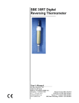
SBE 35 RT
Digital Reversing Thermometer
User’s Manual
Sea-Bird Electronics, Inc.
th
1808 136 Place NE
Bellevue, Washington 98005 USA
Tel: 425/643-9866
Fax:425/643-9954
Limited Liability Statement
Extreme care should be exercised when using or servicing this equipment. It should be used or serviced
only by personnel with knowledge of and training in the use and maintenance of oceanographic
electronic equipment.
SEA-BIRD ELECTRONICS, INC. disclaims all product liability risks arising from the use or servicing
of this system. SEA-BIRD ELECTRONICS, INC. has no way of controlling the use of this equipment
or of choosing the personnel to operate it, and therefore cannot take steps to comply with laws
pertaining to product liability, including laws which impose a duty to warn the user of any dangers
involved in operating this equipment. Therefore, acceptance of this system by the customer shall be
conclusively deemed to include a covenant by the customer to defend, indemnify, and hold SEA-BIRD
ELECTRONICS, INC. harmless from all product liability claims arising from the use or servicing of
this system.
2
Table of Contents
Section 1: Introduction
About this manual………………………………...4
How to contact Sea-Bird………………………….4
Section 2: Communication with the SBE 35 RT…..5
Section 3: SBE 35 RT Commands
Status………………………………………………7
Set Up...……………………………………..…….7
Acquisition….……………………………………..8
Data Upload.………………………………….…...9
Calibration Coefficients…………………………...9
Testing…………………………………………….9
Section 4: Operating the SBE 35 RT
Use with SBE 911plus and
Carousel Water Sampler……….…………………10
Use with SBE 19 or 25 CTD and Carousel
Water Sampler…...……...………………………..11
Section 5: Measurement Cycle…………………….....12
Section 6: Calibration………………………………....13
References
14
Warranty Policy
Service Information
Calibration Certificates
3
1:Introduction
Section 1: Introduction
This section includes contact information and manual
version number.
About this manual
This manual is to be used with the SBE 35 RT Digital Reversing
Thermometer.
It is organized to guide a user from installation through operation and data
collection. We’ve included command descriptions, measurement cycle and
calibration information.
If you have any questions, do not hesitate to contact us at the numbers
below.
Manual Version # 005 03/30/99
How to contact Sea-Bird
Sea-Bird Electronics, Inc.
1808 136th Place Northeast
Bellevue, Washington 98005 USA
Telephone: 425-643-9866
Fax: 425-643-9954
E-mail: seabird@seabird.com
Website: http://www.seabird.com
Our business hours are:
Monday-Friday, 0800 to 1800 Pacific Standard Time
(1600 to 0200 Universal Time)
Except from April to October, when we will be on “summer time”
(1500 to 0100 Universal Time)
4
2:Communication with the SBE 35 RT
Section 2:
Communication with the SBE 35 RT
This section describes the function and features of the SBE 35 RT.
System Description
The SBE 35RT is an accurate ocean-range temperature sensor that can act as a
stand-alone substitute reversing thermometers. When used with a SBE 911plus,
SBE 19, or SBE 25 CTD and Carousel water sampler, the SBE 35RT makes a
temperature measurement each time a bottle fire confirmation is received and
stores the value in EEPROM. Each stored value contains the time of day and
the bottle position in addition to the temperature data to facilitate comparison of
the SBE 35RT record with CTD and water bottle data. The SBE 35RT can use
the built in CTD modem channel for two-way communications. It is not
necessary to change cable connections to communicate and retrieve data from
the SBE 35RT.
Supplied with the SBE 35RT is a powerful software package, SEASOFT, which
enables the user to communicate, retrieve data, and to calculate and display
temperature. SEASOFT as supplied is designed to run on IBM
XT/AT/386/486/Pentium or compatible computers.
A separate software manual contains additional
information on the setup and use of SEASOFT.
5
2:Communication with the SBE 35 RT
Communication with the SBE 35 RT
Use the program TERM35 supplied with the SBE 35RT (or any other terminal
program set to 300 baud, 8 data bit, no parity) to communicate with the SBE
35RT.
For lab use :
1. Connect the SBE 35RT to a SBE 90248 opto-box using cable P/N 80555.
The opto-box isolates power to the SBE 35RT and buffers the serial
communication lines in order to minimize noise input to the SBE 35RT
from external sources.
2.
Connect the 90248 to a serial port on a PC with a straight through cable P/N
80677.
The SBE 35RT communicates at 300 baud, 8 data bits, no parity.
Note: The orange LED will flash when the SBE 35RT transmits. The
green LED will flash when the PC transmits.
3.
The SBE 35RT will transmit "SBE 35RT wake up" three seconds after the
90248 opto-box is powered on.
7
3: SBE 35 RT Commands
Section 3: SBE 35 RT Commands
This section describes the commands associated with TERM35 as
part of SEASOFT.
Command Descriptions
STATUS
ds
Display Status. A typical reply would be:
SBE35 V 2.0 SERIAL NO. 0013 01 Oct 1998 15:56:52
number of measurement cycles to average = 8
number of data points stored in memory = 2
bottle confirm interface = SBE 911plus
S>
dc
Display Calibration Coefficients. A typical reply would be:
SBE35 V 2.0 SERIAL NO. 0013
09-apr-97
A0 = 5.156252707e-03
A1 = -1.430180396e-03
A2 = 2.092145355e-04
A3 = -1.156278215e-05
A4 = 2.446454055e-07
SLOPE = 1.000000
OFFSET = 0.000000
S>
SET UP
ncycles=N
Set the number of measurement cycles per acquisition to N.
Each acquisition cycle is 1.1 seconds in duration.
In a thermally quiet environment the temperature noise
standard deviation is:
0.000029 * sqrt(8 / ncycles) °C
interface=911plus
SBE 35RT is used with a SBE 911plus CTD and Carousel
interface=32serial
SBE 35RT is used with a SBE 19 or 25 CTD and Carousel
samplenum=N
Set the sample number to N. Set N to 0 at the beginning of a
cast after all previous data has been downloaded from the SBE
35RT
7
3: SBE 35 RT Commands
DDMMYY=ddmmyy
MMDDYY=mmddyy
Set current day, month, and year. This command must be
followed by HHMMSS= command to set the time.
Set current month, day, and year. This command must be
followed by HHMMSS= command to set the time.
DDMMYY= and MMDDYY= commands are equivalent.
Either one can be used to set the date.
HHMMSS=hhmmss
Set the current hour, minute, and second.
Example: To set the current date and time to 10 January 1997 12:00:00:
MMDDYY=011097
HHMMSS=120000
or
DDMMYY=100197
HHMMSS=120000
ACQUISITION
Bottle Confirm
Whenever the SBE 35RT receives a valid bottle confirmation sequence (a
character with decimal value 6 followed by a character with decimal value greater
than 48 and less than 84) it takes a measurement ncycles in duration and stores
the date, time, bottle number, maximum - minimum thermistor value, and sensor
output in EEPROM.
ts
Take one sample and store it in EEPROM
cal
Sample continuously, do not compute temperature, do not store samples
Output Format:
column 1:
column 2:
column 3:
column 4:
column 5:
column 6:
column 7:
zero value
reference resistor value
thermistor value
maximum - minimum zero value
maximum - minimum reference resistor value
maximum - minimum thermistor value
sensor output (n)
A typical output with the SBE 35RT in a triple point of water cell with the number of
cycles per measurement = 16 is:
197.21
197.87
197.64
198.08
197.73
197.91
197.71
1047557
1047563
1047565
1047566
1047554
1047555
1047551
752453.3
752457.4
752459.1
752459.9
752451.2
752451.4
752449.1
15
15
15
19
13
17
14
31
31
32
30
34
30
27
27
21
18
21
28
27
21
753130.0
753129.0
753129.5
753129.5
753129.6
753129.2
753129.2
9
3: SBE 35 RT Commands
run
Sample continuously, compute temperature, do not store samples
The output format is the same as in page 8 but with computed temperature added
in the eighth column.
Although the total time per measurement cycle is 1.1 * ncycles seconds the time between
sample updates is 1.1 * ncycles + 2.7 seconds. The extra time is spent converting the
measured values to computed temperature and transmitting the data at 300 baud.
DATA UPLOAD
Dump all the data
dd
ddB,E Dump scans B through E
The format is:
column 1:
column 2,3:
column 4:
column 5:
column 6:
column 7L
sample number
date and time DD MMM YYYY HH:MM:SS
bottle position
maximum - minimum thermistor value
sensor output (n)
computed temperature [ITS-90]
A sample output with the SBE 35RT taking data in room ambient air is:
1 30 Sep 1998 16:15:13 bn = 8 diff = 19 val = 509867.0 t90 = 8.752364
2 30 Sep 1998 16:15:41 bn = 6 diff = 21 val = 509867.4 t90 = 8.752342
0
1
2
3
4
5
30 Sep 1998 10:29:29
30 Sep 1998 10:31:00
30 Sep 1998 10:31:30
30 Sep 1998 10:32:00
30 Sep 1998 10:32:30
30 Sep 1998 10:33:00
bn =
bn =
bn =
bn =
bn =
bn =
1
2
3
4
5
6
diff =
diff =
diff =
diff =
diff =
diff =
268
84
140
357
367
409
val =
val =
val =
val =
val =
val =
278061.1
277430.6
277357.8
277163.3
277055.7
276487.1
CALIBRATION COEFFICIENTS
caldate=sssss
ta0=F
ta1=F
ta2=F
ta3=F
ta4=F
offset=F
slope=F
set the calibration date to sssss (factory programmed)
set A0 coefficient = F (factory programmed)
set A1 coefficient = F (factory programmed)
set A2 coefficient = F (factory programmed)
set A3 coefficient = F (factory programmed)
set A4 coefficient = F (factory programmed)
set the offset to F
set the slope to F
TESTING
*rtctest Test battery backed static RAM in the real-time clock module.
*eetest Test the EEPROM memory. Allow 30 seconds for this test to complete. This
command will destroy all data stored in the EEPROM and will overwrite the
calibration coefficients!
Both the *rtctest and *eetest overwrite data stored in the SBE 35RT SRAM! Re-set
the date, time, and number of cycles to average after running these commands.
9
4: Operating the SBE 35 RT
Section 4: Operating the SBE 35 RT
This section will describe SBE 35 RT operation with
Sea-Bird CTD’s and the Carousel Water Sampler.
Operation
At sea, the SBE 35RT can act as a stand-alone substitute for a reversing
thermometer, recording temperature with each bottle closing. In this
application, the SBE 35RT is mounted in a secure area on the water sampler
frame where the ocean water flushes freely and there is minimal
contamination from the passive thermal mass of the metal frame or active
thermal dissipation from electronic instruments.
The SBE 35RT has a time constant of 0.5 seconds so it will lag the SBE 3 if
temperature is changing during the measurement internal. A first order
correction is: Determine the temporal gradient during the measurement
interval from the secondary SBE 3 temperature data in the .ROS file (g =
temperature gradient [°C/s]).
Gradient-corrected SBE 35RT temperature = SBE 35RT measured
temperature + 0.5 * g.
Use with a SBE 911plus and Carousel Water Sampler
1.
Connect the SBE 11plus deck unit modem channel to a PC using a straight through
serial cable (P/N 80073).
2.
Connect the SBE 35RT to the SBE 9plus and Carousel water sampler using cable Ycable SBE 171220, DWG 32208. The three arms of the Y-cable are labeled SBE 9,
SBE 32, and SBE 35RT. Connect each arm to the proper device.
3.
Power the SBE 9plus with the 11plus deck unit.
4.
Run TERM 35 and send the display status command (DS) to verify communication
with the SBE 35RT. (If no reply is received; press <F2> to bring up the setup form,
select communication set up and check the COMM port setting.) In addition, check
that the bottle confirm interface is correct for the application. If not, type “interface=”
and either 911plus or 32 serial.
5.
Set samplenum to zero and run SEASAVE to acquire the CTD cast.
6.
The SBE 35RT will take a sample each time it receives a bottle confirmation and
store the data in EEPROM. If a second bottle is fired before the SBE 35RT finishes
sampling (1.1 * ncycles + 2 seconds), the SBE 35RT will ignore the second bottle
confirmation.
7.
After the CTD cast run TERM 35. Press Function Key 9 to upload the data. The data
file will be stored with a .ASC extension.
8.
Run DATCNV. In Water Bottle Set Up, select scans marked with bottle confirm bit
as the source of scan range. Set offset to 0.0 and duration = 1.1 * ncycles.
10
4: Operating the SBE 35 RT
Use with a SBE 19 or 25 CTD and Carousel Water Sampler
1.
Connect the SBE 33 deck unit modem channel to a PC using a straight through serial
cable (P/N 80073).
2.
Connect the SBE 35RT to the Carousel water sampler using cable SBE 171221 DWG
32209. This is not a straight through cable. Connect the end labeled SBE 35RT to
the SBE 35RT and the end labeled SBE 32 to the Carousel.
3.
Power the Carousel with the SBE 33 deck unit.
4.
Run TERM 35 and send the display status command (DS) to verify communication
with the SBE 35RT. (If no reply is received; press <F2> to bring up the setup form,
select communication set up and check the COMM port setting.) In addition, check
that the bottle confirm interface is correct for the application. If not, type “interface=”
and either 911plus or 32serial.
5.
Set samplenum to zero and run SEASAVE to acquire the CTD cast.
6.
The SBE 35RT will take a sample each time it receives a bottle confirmation and
store the data in EEPROM. If a second bottle is fired before the SBE 35RT finishes
sampling (1.1 * ncycles + 2 seconds), the SBE 35RT will ignore the second bottle
confirmation.
7.
After the CTD cast, run TERM 35. Press Function Key 9 to upload the data. The
data file will be stored with a .ASC extension.
8.
Run DATCNV. In Water Bottle Set Up, select scans marked with bottle confirm bit
as the source of scan range. Set offset to 0.0 and duration = 1.1 * ncycles.
11
5: Measurement Cycle
Section 5: Measurement Cycle
This section provides description of measurement cycle
for the SBE 35 RT.
The SBE 35RT determines temperature by applying a 1.2 kHz AC excitation to a
reference resistor, zero ohms and an ultrastable thermistor and digitizing the output from
each with a 20 bit delta-sigma A/D converter. The reference resistor is a hermetically
sealed VISHAY VHP202K inside a temperature-controlled oven. The switches are "AllPosition" mercury wetted reed relays with a stable contact resistance. AC excitation and
ratiometric comparison using a common processing channel removes measurement errors
due to parasitic thermocouples, offset voltages, leakage currents, and gain errors.
Maximum power dissipated in the thermistor is 5e-7 watts.
NR
NZ
NT
output from the reference resistor
output from zero ohms
output from the thermistor
Output from the sensor = 1048576 * (NT - NZ) / (NR - NZ)
Each acquisition cycle is:
select zero ohms, wait 0.1 seconds for the output to stabilize
average for 0.267 seconds, this is NZ
select reference resistor, wait 0.1 seconds for the output to stabilize
average for 0.267 seconds, this is NR
select thermistor, wait 0.1 seconds for the output to stabilize
average for 0.267 seconds, this is NT
The total time per cycle is 1.1 second.
The number of the above acquisition cycles per measurement is programmable. Increasing
the number of cycles per measurement increases the time to acquire the sample while
reducing the RMS temperature noise from the sensor. The following RMS noise values
are typical for a SBE 35RT in a triple point of water cell:
Ncycles
Acquisition Time
8
32
8.8 seconds
35.2 seconds
Standard Deviation (°C)
0.000029
0.000014
Temperature is computed using the Steinhart-Hart polynomial for thermistors (Steinhart
and Hart, 1968; Bennett, 1972) as follows (n is the output from the SBE 35RT):
t90L =
1.0
-273.15
a0 + a1ln(n) + a2ln2(n) + a3ln3(n) + a4ln4(n)
t90 = slope x t90L + offset
[deg C, ITS-90]
Carrying the polynomial to fourth order captures the non-linearity of the SBE 35RT
thermistor output to better than ± 0.0001 °C.
12
6: Calibration
Section 6: Calibration
SBE 35RTs are calibrated to ITS-90 temperature using Sea-Bird's computercontrolled calibration bath. Extremely well insulated, the baths provide a
uniform toroidal circulation yielding an overall transfer accuracy against an
SPRT within 0.0002°C. Repeatability at each of twelve individually mapped
sensor positions is better than 0.0001°C. Sea-Bird's new metrology laboratory
underpins the new temperature calibration baths. Following consultation with the
U.S. National Institute of Standards and Technology, the met lab was configured
to achieve temperature precision of 50 µK and accuracy of 0.0005 °C. To obtain
this performance, premium primary references including four Jarrett water triplepoint cells (with maintenance bath) and an Isotech gallium melt cell are operated
in conjunction with two YSI 8163 standards-grade platinum resistance
thermometers and an ASL F18 Automatic Temperature Bridge.
13
References
References
Steinhart, J.S. and Hart, S.R. (1968) "Calibration Curves for Thermistors", Deep-Sea Research, 15, p.497.
Bennett, A.S. (1972) "The Calibration of Thermistors over the Temperature range 0-30 °C", Deep-Sea Research, 19, p.157.
14


