1
RAVO 5-Series
RAVO
USER MANUAL
These user instructions are a translation of the original user instructions:
RAVO bv
A Groupe FAYAT SA Subsidiary
Postbus 286, 1800 AG Alkmaar
The Netherlands
Tel: +31 (0) 72 5673232
Fax: +31 (0) 72 5673200
HTTP://WWW.RAVO-FAYAT.COM
1
5 February 2015 12:49 pm
RAVO 5-Series
NOTES
Ensure that this manual is always accessible in the cabin whilst the vehicle is in use. This is important to ensure the correct operation of the
machine. Familiarise yourself with the information in this manual before operating the machine.
In view of the continuous product development, RAVO BV retains the right to make amendments to the user manual without giving prior notice.
Please contact RAVO BV for up-to-date information.
No information from this user manual should be copied and / or published in print, by photocopying or any other means without the prior written
approval of RAVO bv.
Printed in The Netherlands Copyright. RAVO bv
RAVO 5-Series MkV * H
DOCUMENT NUMBER:5009894
VERSION:REV.000
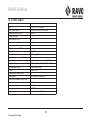
REV. N0. DESCRIPTION
IMPLEMENTATION RW DATA
DATUM
2
5 February 2015 12:49 pm
RAVO 5-Series
A. TECHNICAL SPECIFICATIONS. . . . . . . . . . . . . . . . . . . . . . . . . . . . . . .19
A. 1 Machine dimensions. . . . . . . . . . . . . . . . . . . . . . . . . . . . . . . . . . . . . . . . . . . . . . . . . . . . . . . .20
A. 2 Machine weight . . . . . . . . . . . . . . . . . . . . . . . . . . . . . . . . . . . . . . . . . . . . . . . . . . . . . . . . . . . .20
A. 3 Container . . . . . . . . . . . . . . . . . . . . . . . . . . . . . . . . . . . . . . . . . . . . . . . . . . . . . . . . . . . . . . . . .20
A. 4 TIER3 engine . . . . . . . . . . . . . . . . . . . . . . . . . . . . . . . . . . . . . . . . . . . . . . . . . . . . . . . . . . . . . .21
A. 5 EURO5 engine . . . . . . . . . . . . . . . . . . . . . . . . . . . . . . . . . . . . . . . . . . . . . . . . . . . . . . . . . . . . .22
A. 6 Fan . . . . . . . . . . . . . . . . . . . . . . . . . . . . . . . . . . . . . . . . . . . . . . . . . . . . . . . . . . . . . . . . . . . . . .23
A. 7 Sweeper unit . . . . . . . . . . . . . . . . . . . . . . . . . . . . . . . . . . . . . . . . . . . . . . . . . . . . . . . . . . . . . .23
A. 8 Water system. . . . . . . . . . . . . . . . . . . . . . . . . . . . . . . . . . . . . . . . . . . . . . . . . . . . . . . . . . . . . .23
A. 9 Drive . . . . . . . . . . . . . . . . . . . . . . . . . . . . . . . . . . . . . . . . . . . . . . . . . . . . . . . . . . . . . . . . . . . . .23
A. 10 Front axle and suspension . . . . . . . . . . . . . . . . . . . . . . . . . . . . . . . . . . . . . . . . . . . . . . . . .24
A. 11 Brake system. . . . . . . . . . . . . . . . . . . . . . . . . . . . . . . . . . . . . . . . . . . . . . . . . . . . . . . . . . . . .24
A. 12 Tyres . . . . . . . . . . . . . . . . . . . . . . . . . . . . . . . . . . . . . . . . . . . . . . . . . . . . . . . . . . . . . . . . . . .24
A. 13 Electrical system. . . . . . . . . . . . . . . . . . . . . . . . . . . . . . . . . . . . . . . . . . . . . . . . . . . . . . . . . .24
A. 14 Hydraulic system . . . . . . . . . . . . . . . . . . . . . . . . . . . . . . . . . . . . . . . . . . . . . . . . . . . . . . . . .25
A. 15 Hydraulic system . . . . . . . . . . . . . . . . . . . . . . . . . . . . . . . . . . . . . . . . . . . . . . . . . . . . . . . . .26
A. 16 Air conditioning (optional) . . . . . . . . . . . . . . . . . . . . . . . . . . . . . . . . . . . . . . . . . . . . . . . . . .26
A. 17 Lights . . . . . . . . . . . . . . . . . . . . . . . . . . . . . . . . . . . . . . . . . . . . . . . . . . . . . . . . . . . . . . . . . . .27
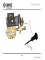
A. 18 High pressure water pump (Optional). . . . . . . . . . . . . . . . . . . . . . . . . . . . . . . . . . . . . . . . .27
A. 19 Lubricating grease . . . . . . . . . . . . . . . . . . . . . . . . . . . . . . . . . . . . . . . . . . . . . . . . . . . . . . . .27
A. 20 Noise . . . . . . . . . . . . . . . . . . . . . . . . . . . . . . . . . . . . . . . . . . . . . . . . . . . . . . . . . . . . . . . . . . .27
A. 21 AdBlue . . . . . . . . . . . . . . . . . . . . . . . . . . . . . . . . . . . . . . . . . . . . . . . . . . . . . . . . . . . . . . . . . .27
A. 22 Vibrations . . . . . . . . . . . . . . . . . . . . . . . . . . . . . . . . . . . . . . . . . . . . . . . . . . . . . . . . . . . . . . .28
3
5 February 2015 12:49 pm
RAVO 5-Series
B. SAFETY . . . . . . . . . . . . . . . . . . . . . . . . . . . . . . . . . . . . . . . . . . . . . . . . . 29
B. 1 Recognizing safety information. . . . . . . . . . . . . . . . . . . . . . . . . . . . . . . . . . . . . . . . . . . . . . .30
B. 2 Explanation of the signal words . . . . . . . . . . . . . . . . . . . . . . . . . . . . . . . . . . . . . . . . . . . . . .30
B. 3 General safety instructions . . . . . . . . . . . . . . . . . . . . . . . . . . . . . . . . . . . . . . . . . . . . . . . . . .31
B. 3.1 Use the machine specification. . . . . . . . . . . . . . . . . . . . . . . . . . . . . . . . . . . . . . . . . . . . . . . . . . . . . . . . . . . . . . . . . . 31
B. 3.2 Use outside the machine specification. . . . . . . . . . . . . . . . . . . . . . . . . . . . . . . . . . . . . . . . . . . . . . . . . . . . . . . . . . . 31
B. 3.3 User/operator. . . . . . . . . . . . . . . . . . . . . . . . . . . . . . . . . . . . . . . . . . . . . . . . . . . . . . . . . . . . . . . . . . . . . . . . . . . . . . . . 31
B. 3.4 Maintenance . . . . . . . . . . . . . . . . . . . . . . . . . . . . . . . . . . . . . . . . . . . . . . . . . . . . . . . . . . . . . . . . . . . . . . . . . . . . . . . . 31
B. 3.5 Wear suitable clothing and safety equipment . . . . . . . . . . . . . . . . . . . . . . . . . . . . . . . . . . . . . . . . . . . . . . . . . . . . . 32
B. 3.6 Be careful with fuel and take measures to prevent a fire. . . . . . . . . . . . . . . . . . . . . . . . . . . . . . . . . . . . . . . . . . . . 32
B. 3.7 Avoid contact with moving parts. . . . . . . . . . . . . . . . . . . . . . . . . . . . . . . . . . . . . . . . . . . . . . . . . . . . . . . . . . . . . . . . 33
B. 3.8 Avoid contact with hot surfaces . . . . . . . . . . . . . . . . . . . . . . . . . . . . . . . . . . . . . . . . . . . . . . . . . . . . . . . . . . . . . . . . 33
B. 3.9 Prevent battery explosions . . . . . . . . . . . . . . . . . . . . . . . . . . . . . . . . . . . . . . . . . . . . . . . . . . . . . . . . . . . . . . . . . . . . 33
B. 3.10 Avoid contact with high-pressure liquids. . . . . . . . . . . . . . . . . . . . . . . . . . . . . . . . . . . . . . . . . . . . . . . . . . . . . . . . 34
B. 3.11 Use the correct equipment and service components . . . . . . . . . . . . . . . . . . . . . . . . . . . . . . . . . . . . . . . . . . . . . . 34
B. 3.12 Comply with environmental regulations. . . . . . . . . . . . . . . . . . . . . . . . . . . . . . . . . . . . . . . . . . . . . . . . . . . . . . . . . 35
B. 3.13 Carry out maintenance work safely. . . . . . . . . . . . . . . . . . . . . . . . . . . . . . . . . . . . . . . . . . . . . . . . . . . . . . . . . . . . . 35
B. 3.14 Take a break in good time . . . . . . . . . . . . . . . . . . . . . . . . . . . . . . . . . . . . . . . . . . . . . . . . . . . . . . . . . . . . . . . . . . . . 35
B. 3.15 Exhaust gasses . . . . . . . . . . . . . . . . . . . . . . . . . . . . . . . . . . . . . . . . . . . . . . . . . . . . . . . . . . . . . . . . . . . . . . . . . . . . . 35
B. 4 Scrapping the sweeper. . . . . . . . . . . . . . . . . . . . . . . . . . . . . . . . . . . . . . . . . . . . . . . . . . . . . .36
B. 4.1 Activities to be completed . . . . . . . . . . . . . . . . . . . . . . . . . . . . . . . . . . . . . . . . . . . . . . . . . . . . . . . . . . . . . . . . . . . . . 36
B. 5 Sweeper emergency stop. . . . . . . . . . . . . . . . . . . . . . . . . . . . . . . . . . . . . . . . . . . . . . . . . . . .39
B. 5.1 Operating the emergency stop . . . . . . . . . . . . . . . . . . . . . . . . . . . . . . . . . . . . . . . . . . . . . . . . . . . . . . . . . . . . . . . . . 39
B. 5.2 Reset the emergency stop . . . . . . . . . . . . . . . . . . . . . . . . . . . . . . . . . . . . . . . . . . . . . . . . . . . . . . . . . . . . . . . . . . . . . 39
B. 6 Transporting the sweeper . . . . . . . . . . . . . . . . . . . . . . . . . . . . . . . . . . . . . . . . . . . . . . . . . . .41
B. 6.1 Securing. . . . . . . . . . . . . . . . . . . . . . . . . . . . . . . . . . . . . . . . . . . . . . . . . . . . . . . . . . . . . . . . . . . . . . . . . . . . . . . . . . . . 41
4
5 February 2015 12:49 pm
RAVO 5-Series
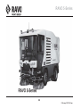
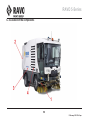
C. PRODUCT DESCRIPTION . . . . . . . . . . . . . . . . . . . . . . . . . . . . . . . . . . .43
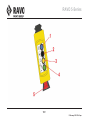
C. 1 Vehicle description . . . . . . . . . . . . . . . . . . . . . . . . . . . . . . . . . . . . . . . . . . . . . . . . . . . . . . . . .45
C. 2 Vehicle operation . . . . . . . . . . . . . . . . . . . . . . . . . . . . . . . . . . . . . . . . . . . . . . . . . . . . . . . . . .47
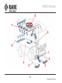
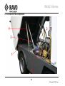
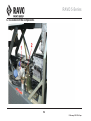
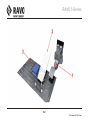
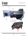
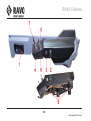
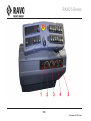
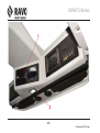
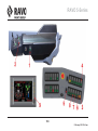
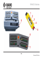
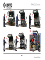
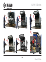
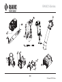
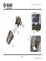
C. 3 Location of the components . . . . . . . . . . . . . . . . . . . . . . . . . . . . . . . . . . . . . . . . . . . . . . . . .48
C. 4 Location of the components . . . . . . . . . . . . . . . . . . . . . . . . . . . . . . . . . . . . . . . . . . . . . . . . .50
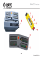
C. 5 Location of the components . . . . . . . . . . . . . . . . . . . . . . . . . . . . . . . . . . . . . . . . . . . . . . . . .52
C. 6 Location of the components . . . . . . . . . . . . . . . . . . . . . . . . . . . . . . . . . . . . . . . . . . . . . . . . .54
C. 7 Location of the components . . . . . . . . . . . . . . . . . . . . . . . . . . . . . . . . . . . . . . . . . . . . . . . . .56
C. 8 Location of the components . . . . . . . . . . . . . . . . . . . . . . . . . . . . . . . . . . . . . . . . . . . . . . . . .58
C. 9 Location of the components . . . . . . . . . . . . . . . . . . . . . . . . . . . . . . . . . . . . . . . . . . . . . . . . .60
C. 10 Location of the components . . . . . . . . . . . . . . . . . . . . . . . . . . . . . . . . . . . . . . . . . . . . . . . .62
C. 11 Location of the components . . . . . . . . . . . . . . . . . . . . . . . . . . . . . . . . . . . . . . . . . . . . . . . .64
C. 12 CE declaration of conformity . . . . . . . . . . . . . . . . . . . . . . . . . . . . . . . . . . . . . . . . . . . . . . . .67
C. 13 Vehicle Identification Number (VIN) . . . . . . . . . . . . . . . . . . . . . . . . . . . . . . . . . . . . . . . . . .69
C. 13.1 Explanation of the Vehicle Identification Number (VIN) . . . . . . . . . . . . . . . . . . . . . . . . . . . . . . . . . . . . . . . . . . . . 69
D. OPERATING CONTROLS . . . . . . . . . . . . . . . . . . . . . . . . . . . . . . . . . . .71
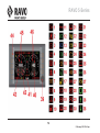
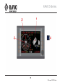
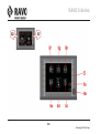
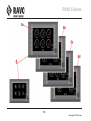
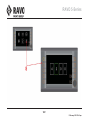
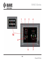
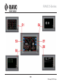
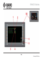
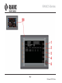
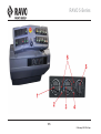
D. 1 iSystem LED screen ‘Drive’ . . . . . . . . . . . . . . . . . . . . . . . . . . . . . . . . . . . . . . . . . . . . . . . . . .73
D. 1.1 Air filter indicator light (option) . . . . . . . . . . . . . . . . . . . . . . . . . . . . . . . . . . . . . . . . . . . . . . . . . . . . . . . . . . . . . . . .
D. 1.2 Fuel filter indicator light . . . . . . . . . . . . . . . . . . . . . . . . . . . . . . . . . . . . . . . . . . . . . . . . . . . . . . . . . . . . . . . . . . . . . .
D. 1.3 Hydraulic oil filter indicator light (option) . . . . . . . . . . . . . . . . . . . . . . . . . . . . . . . . . . . . . . . . . . . . . . . . . . . . . . . .
D. 1.4 Hydraulic oil level indicator light . . . . . . . . . . . . . . . . . . . . . . . . . . . . . . . . . . . . . . . . . . . . . . . . . . . . . . . . . . . . . . .
D. 1.5 Drive temperature indicator light . . . . . . . . . . . . . . . . . . . . . . . . . . . . . . . . . . . . . . . . . . . . . . . . . . . . . . . . . . . . . . .
5
5 February 2015 12:49 pm
73
73
73
73
73
RAVO 5-Series
D. 1.6 Sweeping limited. . . . . . . . . . . . . . . . . . . . . . . . . . . . . . . . . . . . . . . . . . . . . . . . . . . . . . . . . . . . . . . . . . . . . . . . . . . . . 75
D. 1.7 Engine start indicator light. . . . . . . . . . . . . . . . . . . . . . . . . . . . . . . . . . . . . . . . . . . . . . . . . . . . . . . . . . . . . . . . . . . . . 75
D. 1.8 Alternator indicator light . . . . . . . . . . . . . . . . . . . . . . . . . . . . . . . . . . . . . . . . . . . . . . . . . . . . . . . . . . . . . . . . . . . . . . 75
D. 1.9 Coolant indicator light . . . . . . . . . . . . . . . . . . . . . . . . . . . . . . . . . . . . . . . . . . . . . . . . . . . . . . . . . . . . . . . . . . . . . . . . 75
D. 1.10 Fuel indicator light . . . . . . . . . . . . . . . . . . . . . . . . . . . . . . . . . . . . . . . . . . . . . . . . . . . . . . . . . . . . . . . . . . . . . . . . . . 75
D. 1.11 Engine oil pressure indicator light . . . . . . . . . . . . . . . . . . . . . . . . . . . . . . . . . . . . . . . . . . . . . . . . . . . . . . . . . . . . . 75
D. 1.12 Dipped beam indicator light. . . . . . . . . . . . . . . . . . . . . . . . . . . . . . . . . . . . . . . . . . . . . . . . . . . . . . . . . . . . . . . . . . . 75
D. 1.13 Main beam indicator light. . . . . . . . . . . . . . . . . . . . . . . . . . . . . . . . . . . . . . . . . . . . . . . . . . . . . . . . . . . . . . . . . . . . . 77
D. 1.14 Fog light indicator light . . . . . . . . . . . . . . . . . . . . . . . . . . . . . . . . . . . . . . . . . . . . . . . . . . . . . . . . . . . . . . . . . . . . . . 77
D. 1.15 Indicator beacon light. . . . . . . . . . . . . . . . . . . . . . . . . . . . . . . . . . . . . . . . . . . . . . . . . . . . . . . . . . . . . . . . . . . . . . . . 77
D. 1.16 Heated mirror indicator light (option) . . . . . . . . . . . . . . . . . . . . . . . . . . . . . . . . . . . . . . . . . . . . . . . . . . . . . . . . . . . 77
D. 1.17 Water in fuel. . . . . . . . . . . . . . . . . . . . . . . . . . . . . . . . . . . . . . . . . . . . . . . . . . . . . . . . . . . . . . . . . . . . . . . . . . . . . . . . 77
D. 1.18 Brake fluid pressure indicator light. . . . . . . . . . . . . . . . . . . . . . . . . . . . . . . . . . . . . . . . . . . . . . . . . . . . . . . . . . . . . 77
D. 1.19 ABS indicator light . . . . . . . . . . . . . . . . . . . . . . . . . . . . . . . . . . . . . . . . . . . . . . . . . . . . . . . . . . . . . . . . . . . . . . . . . . 77
D. 1.20 Steering and brake fluid temperature indicator light (Option ABS) . . . . . . . . . . . . . . . . . . . . . . . . . . . . . . . . . . . 77
D. 1.21 Steering and brake fluid level indicator light . . . . . . . . . . . . . . . . . . . . . . . . . . . . . . . . . . . . . . . . . . . . . . . . . . . . . 77
D. 1.22 Exhaust cleaning stop (Tier 4) . . . . . . . . . . . . . . . . . . . . . . . . . . . . . . . . . . . . . . . . . . . . . . . . . . . . . . . . . . . . . . . . . 77
D. 1.23 Exhaust cleaning (Tier 4) . . . . . . . . . . . . . . . . . . . . . . . . . . . . . . . . . . . . . . . . . . . . . . . . . . . . . . . . . . . . . . . . . . . . . 77
D. 1.24 Engine Data Controller (EDC) indicator light . . . . . . . . . . . . . . . . . . . . . . . . . . . . . . . . . . . . . . . . . . . . . . . . . . . . . 79
D. 1.25 EDC indicator light . . . . . . . . . . . . . . . . . . . . . . . . . . . . . . . . . . . . . . . . . . . . . . . . . . . . . . . . . . . . . . . . . . . . . . . . . . 79
D. 1.26 OBD emission values indicator light. . . . . . . . . . . . . . . . . . . . . . . . . . . . . . . . . . . . . . . . . . . . . . . . . . . . . . . . . . . . 79
D. 1.27 On-board computer indicator light . . . . . . . . . . . . . . . . . . . . . . . . . . . . . . . . . . . . . . . . . . . . . . . . . . . . . . . . . . . . . 79
D. 1.28 Parking brake indicator light (handbrake) . . . . . . . . . . . . . . . . . . . . . . . . . . . . . . . . . . . . . . . . . . . . . . . . . . . . . . . 79
D. 1.29 Engine stop indicator light. . . . . . . . . . . . . . . . . . . . . . . . . . . . . . . . . . . . . . . . . . . . . . . . . . . . . . . . . . . . . . . . . . . . 79
D. 1.30 MSC indicator light . . . . . . . . . . . . . . . . . . . . . . . . . . . . . . . . . . . . . . . . . . . . . . . . . . . . . . . . . . . . . . . . . . . . . . . . . . 79
D. 1.31 Container rear door indicator light (only CD version) . . . . . . . . . . . . . . . . . . . . . . . . . . . . . . . . . . . . . . . . . . . . . . 79
D. 1.32 Container pusher indicator light (only CD version) . . . . . . . . . . . . . . . . . . . . . . . . . . . . . . . . . . . . . . . . . . . . . . . . 79
D. 1.33 Container service doors indicator light (only CD version) . . . . . . . . . . . . . . . . . . . . . . . . . . . . . . . . . . . . . . . . . . 81
6
5 February 2015 12:49 pm
RAVO 5-Series
D. 1.34 Container raised indicator light . . . . . . . . . . . . . . . . . . . . . . . . . . . . . . . . . . . . . . . . . . . . . . . . . . . . . . . . . . . . . . .
D. 1.35 Engine coolant level indicator light (only Tier 4) . . . . . . . . . . . . . . . . . . . . . . . . . . . . . . . . . . . . . . . . . . . . . . . . .
D. 1.36 Direction indicators . . . . . . . . . . . . . . . . . . . . . . . . . . . . . . . . . . . . . . . . . . . . . . . . . . . . . . . . . . . . . . . . . . . . . . . . .
D. 1.37 Exhaust temperature indicator light (Euro 6 and Tier 4) . . . . . . . . . . . . . . . . . . . . . . . . . . . . . . . . . . . . . . . . . . .
D. 1.38 Direction indicator . . . . . . . . . . . . . . . . . . . . . . . . . . . . . . . . . . . . . . . . . . . . . . . . . . . . . . . . . . . . . . . . . . . . . . . . . .
D. 1.39 Rotation/selection knob. . . . . . . . . . . . . . . . . . . . . . . . . . . . . . . . . . . . . . . . . . . . . . . . . . . . . . . . . . . . . . . . . . . . . .
D. 1.40 Spraywater level gauge . . . . . . . . . . . . . . . . . . . . . . . . . . . . . . . . . . . . . . . . . . . . . . . . . . . . . . . . . . . . . . . . . . . . . .
D. 1.41 Clock . . . . . . . . . . . . . . . . . . . . . . . . . . . . . . . . . . . . . . . . . . . . . . . . . . . . . . . . . . . . . . . . . . . . . . . . . . . . . . . . . . . . .
D. 1.42 AdBlue level gauge . . . . . . . . . . . . . . . . . . . . . . . . . . . . . . . . . . . . . . . . . . . . . . . . . . . . . . . . . . . . . . . . . . . . . . . . .
D. 1.43 Fuel level gauge . . . . . . . . . . . . . . . . . . . . . . . . . . . . . . . . . . . . . . . . . . . . . . . . . . . . . . . . . . . . . . . . . . . . . . . . . . . .
D. 1.44 Selection knob . . . . . . . . . . . . . . . . . . . . . . . . . . . . . . . . . . . . . . . . . . . . . . . . . . . . . . . . . . . . . . . . . . . . . . . . . . . . .
D. 1.45 Speedometer. . . . . . . . . . . . . . . . . . . . . . . . . . . . . . . . . . . . . . . . . . . . . . . . . . . . . . . . . . . . . . . . . . . . . . . . . . . . . . .
D. 1.46 Rev. counter . . . . . . . . . . . . . . . . . . . . . . . . . . . . . . . . . . . . . . . . . . . . . . . . . . . . . . . . . . . . . . . . . . . . . . . . . . . . . . .
81
81
81
81
81
81
81
81
81
83
83
83
83
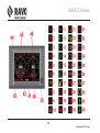
D. 2 iSystem LED display – sweeping . . . . . . . . . . . . . . . . . . . . . . . . . . . . . . . . . . . . . . . . . . . . .85
D. 2.1 Silent indicator light (option) . . . . . . . . . . . . . . . . . . . . . . . . . . . . . . . . . . . . . . . . . . . . . . . . . . . . . . . . . . . . . . . . . .
D. 2.2 Fan indicator light . . . . . . . . . . . . . . . . . . . . . . . . . . . . . . . . . . . . . . . . . . . . . . . . . . . . . . . . . . . . . . . . . . . . . . . . . . .
D. 2.3 Suction nozzle indicator light . . . . . . . . . . . . . . . . . . . . . . . . . . . . . . . . . . . . . . . . . . . . . . . . . . . . . . . . . . . . . . . . . .
D. 2.4 Spraywater pump indicator light . . . . . . . . . . . . . . . . . . . . . . . . . . . . . . . . . . . . . . . . . . . . . . . . . . . . . . . . . . . . . . .
D. 2.5 Water recirculation indicator light (option) . . . . . . . . . . . . . . . . . . . . . . . . . . . . . . . . . . . . . . . . . . . . . . . . . . . . . . .
D. 2.6 HP water pump (option). . . . . . . . . . . . . . . . . . . . . . . . . . . . . . . . . . . . . . . . . . . . . . . . . . . . . . . . . . . . . . . . . . . . . . .
D. 2.7 Speedometer. . . . . . . . . . . . . . . . . . . . . . . . . . . . . . . . . . . . . . . . . . . . . . . . . . . . . . . . . . . . . . . . . . . . . . . . . . . . . . . .
D. 2.8 Rev. counter . . . . . . . . . . . . . . . . . . . . . . . . . . . . . . . . . . . . . . . . . . . . . . . . . . . . . . . . . . . . . . . . . . . . . . . . . . . . . . . .
D. 2.9 Ideal sweep rev range . . . . . . . . . . . . . . . . . . . . . . . . . . . . . . . . . . . . . . . . . . . . . . . . . . . . . . . . . . . . . . . . . . . . . . . .
D. 2.10 Lighting . . . . . . . . . . . . . . . . . . . . . . . . . . . . . . . . . . . . . . . . . . . . . . . . . . . . . . . . . . . . . . . . . . . . . . . . . . . . . . . . . . .
D. 2.11 Brush washers . . . . . . . . . . . . . . . . . . . . . . . . . . . . . . . . . . . . . . . . . . . . . . . . . . . . . . . . . . . . . . . . . . . . . . . . . . . . .
D. 2.12 Brush speed . . . . . . . . . . . . . . . . . . . . . . . . . . . . . . . . . . . . . . . . . . . . . . . . . . . . . . . . . . . . . . . . . . . . . . . . . . . . . . .
D. 2.13 Suction nozzle and suction tube sprayers . . . . . . . . . . . . . . . . . . . . . . . . . . . . . . . . . . . . . . . . . . . . . . . . . . . . . .
D. 2.14 Water level gauge. . . . . . . . . . . . . . . . . . . . . . . . . . . . . . . . . . . . . . . . . . . . . . . . . . . . . . . . . . . . . . . . . . . . . . . . . . .
7
5 February 2015 12:49 pm
85
85
85
85
85
85
85
85
85
85
85
85
87
87
RAVO 5-Series
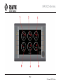
D. 3 iSystem LED display ‘Dump’ . . . . . . . . . . . . . . . . . . . . . . . . . . . . . . . . . . . . . . . . . . . . . . . . .89
D. 3.1 Dump status indicator . . . . . . . . . . . . . . . . . . . . . . . . . . . . . . . . . . . . . . . . . . . . . . . . . . . . . . . . . . . . . . . . . . . . . . . . 89
D. 3.2 Rev. counter . . . . . . . . . . . . . . . . . . . . . . . . . . . . . . . . . . . . . . . . . . . . . . . . . . . . . . . . . . . . . . . . . . . . . . . . . . . . . . . . 89
D. 3.3 Speedometer . . . . . . . . . . . . . . . . . . . . . . . . . . . . . . . . . . . . . . . . . . . . . . . . . . . . . . . . . . . . . . . . . . . . . . . . . . . . . . . . 89
D. 3.4 HP water pump (option) . . . . . . . . . . . . . . . . . . . . . . . . . . . . . . . . . . . . . . . . . . . . . . . . . . . . . . . . . . . . . . . . . . . . . . . 89
D. 4 Dashboard . . . . . . . . . . . . . . . . . . . . . . . . . . . . . . . . . . . . . . . . . . . . . . . . . . . . . . . . . . . . . . . .91
D. 4.1 Hand accelerator activation button . . . . . . . . . . . . . . . . . . . . . . . . . . . . . . . . . . . . . . . . . . . . . . . . . . . . . . . . . . . . . . 91
D. 4.2 Brush switch (with ‘independently lifting of right brush’ option) . . . . . . . . . . . . . . . . . . . . . . . . . . . . . . . . . . . . . 91
D. 4.3 Spraywater pump switch . . . . . . . . . . . . . . . . . . . . . . . . . . . . . . . . . . . . . . . . . . . . . . . . . . . . . . . . . . . . . . . . . . . . . . 93
D. 4.4 Fan switch . . . . . . . . . . . . . . . . . . . . . . . . . . . . . . . . . . . . . . . . . . . . . . . . . . . . . . . . . . . . . . . . . . . . . . . . . . . . . . . . . . 93
D. 4.5 Suction nozzle switch, raise/lower . . . . . . . . . . . . . . . . . . . . . . . . . . . . . . . . . . . . . . . . . . . . . . . . . . . . . . . . . . . . . . 93
D. 4.6 Brush switch (with ‘independently lifting of left brush’ option) . . . . . . . . . . . . . . . . . . . . . . . . . . . . . . . . . . . . . . . 95
D. 4.7 Brush speed regulator . . . . . . . . . . . . . . . . . . . . . . . . . . . . . . . . . . . . . . . . . . . . . . . . . . . . . . . . . . . . . . . . . . . . . . . . 95
D. 4.8 Third brush speed regulator (option) . . . . . . . . . . . . . . . . . . . . . . . . . . . . . . . . . . . . . . . . . . . . . . . . . . . . . . . . . . . . 95
D. 4.9 Third brush double angle adjustment switch (option) . . . . . . . . . . . . . . . . . . . . . . . . . . . . . . . . . . . . . . . . . . . . . . 95
D. 4.10 Third brush angle adjustment regulator (option). . . . . . . . . . . . . . . . . . . . . . . . . . . . . . . . . . . . . . . . . . . . . . . . . . 95
D. 4.11 Third brush spraywater switch (option) . . . . . . . . . . . . . . . . . . . . . . . . . . . . . . . . . . . . . . . . . . . . . . . . . . . . . . . . . 95
D. 4.12 Ride-height control switch, front axle. . . . . . . . . . . . . . . . . . . . . . . . . . . . . . . . . . . . . . . . . . . . . . . . . . . . . . . . . . . 97
D. 4.13 Third brush motor rotation direction switch . . . . . . . . . . . . . . . . . . . . . . . . . . . . . . . . . . . . . . . . . . . . . . . . . . . . . 97
D. 4.14 Dump/Drive/Sweep switch . . . . . . . . . . . . . . . . . . . . . . . . . . . . . . . . . . . . . . . . . . . . . . . . . . . . . . . . . . . . . . . . . . . . 99
D. 4.15 12V connection . . . . . . . . . . . . . . . . . . . . . . . . . . . . . . . . . . . . . . . . . . . . . . . . . . . . . . . . . . . . . . . . . . . . . . . . . . . . . 99
D. 4.16 Suction nozzle lighting switch/3rd brush lighting (option) . . . . . . . . . . . . . . . . . . . . . . . . . . . . . . . . . . . . . . . . . . 99
D. 4.17 Brush lighting, right/left . . . . . . . . . . . . . . . . . . . . . . . . . . . . . . . . . . . . . . . . . . . . . . . . . . . . . . . . . . . . . . . . . . . . . . 99
D. 4.18 High pressure water pump switch (option)/Swasher (option) . . . . . . . . . . . . . . . . . . . . . . . . . . . . . . . . . . . . . . . 99
D. 4.19 Operating light(s) (option) . . . . . . . . . . . . . . . . . . . . . . . . . . . . . . . . . . . . . . . . . . . . . . . . . . . . . . . . . . . . . . . . . . . . 99
D. 4.20 Water recirculation system (option) . . . . . . . . . . . . . . . . . . . . . . . . . . . . . . . . . . . . . . . . . . . . . . . . . . . . . . . . . . . . 101
D. 4.21 Brush angle adjustment left (option) . . . . . . . . . . . . . . . . . . . . . . . . . . . . . . . . . . . . . . . . . . . . . . . . . . . . . . . . . . . 101
D. 4.22 Suction nozzle camera (option) . . . . . . . . . . . . . . . . . . . . . . . . . . . . . . . . . . . . . . . . . . . . . . . . . . . . . . . . . . . . . . . . 101
8
5 February 2015 12:49 pm
RAVO 5-Series
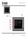
D. 5 iSystem . . . . . . . . . . . . . . . . . . . . . . . . . . . . . . . . . . . . . . . . . . . . . . . . . . . . . . . . . . . . . . . . . .103
D. 5.1 Function keys . . . . . . . . . . . . . . . . . . . . . . . . . . . . . . . . . . . . . . . . . . . . . . . . . . . . . . . . . . . . . . . . . . . . . . . . . . . . . . .
D. 5.2 Information screens . . . . . . . . . . . . . . . . . . . . . . . . . . . . . . . . . . . . . . . . . . . . . . . . . . . . . . . . . . . . . . . . . . . . . . . . . .
D. 5.3 Start-up screen (1) . . . . . . . . . . . . . . . . . . . . . . . . . . . . . . . . . . . . . . . . . . . . . . . . . . . . . . . . . . . . . . . . . . . . . . . . . . .
D. 5.4 Driving screen (2) . . . . . . . . . . . . . . . . . . . . . . . . . . . . . . . . . . . . . . . . . . . . . . . . . . . . . . . . . . . . . . . . . . . . . . . . . . . .
D. 5.5 Sweeping screen (3). . . . . . . . . . . . . . . . . . . . . . . . . . . . . . . . . . . . . . . . . . . . . . . . . . . . . . . . . . . . . . . . . . . . . . . . . .
D. 5.6 Dumping screen (4) . . . . . . . . . . . . . . . . . . . . . . . . . . . . . . . . . . . . . . . . . . . . . . . . . . . . . . . . . . . . . . . . . . . . . . . . . .
D. 5.7 Main menu screen (5). . . . . . . . . . . . . . . . . . . . . . . . . . . . . . . . . . . . . . . . . . . . . . . . . . . . . . . . . . . . . . . . . . . . . . . . .
D. 5.8 iSystem telemetry screens (6). . . . . . . . . . . . . . . . . . . . . . . . . . . . . . . . . . . . . . . . . . . . . . . . . . . . . . . . . . . . . . . . . .
D. 5.9 Telemetry screen (6a) . . . . . . . . . . . . . . . . . . . . . . . . . . . . . . . . . . . . . . . . . . . . . . . . . . . . . . . . . . . . . . . . . . . . . . . .
D. 5.10 Telemetry screen (6b) . . . . . . . . . . . . . . . . . . . . . . . . . . . . . . . . . . . . . . . . . . . . . . . . . . . . . . . . . . . . . . . . . . . . . . .
D. 5.11 Telemetry screen (6c) . . . . . . . . . . . . . . . . . . . . . . . . . . . . . . . . . . . . . . . . . . . . . . . . . . . . . . . . . . . . . . . . . . . . . . .
D. 5.12 Telemetry screen (6d) . . . . . . . . . . . . . . . . . . . . . . . . . . . . . . . . . . . . . . . . . . . . . . . . . . . . . . . . . . . . . . . . . . . . . . .
D. 5.13 Display settings menu (7) . . . . . . . . . . . . . . . . . . . . . . . . . . . . . . . . . . . . . . . . . . . . . . . . . . . . . . . . . . . . . . . . . . . .
D. 5.14 Dealer login menu (8). . . . . . . . . . . . . . . . . . . . . . . . . . . . . . . . . . . . . . . . . . . . . . . . . . . . . . . . . . . . . . . . . . . . . . . .
D. 5.15 iSystem check menu (9) . . . . . . . . . . . . . . . . . . . . . . . . . . . . . . . . . . . . . . . . . . . . . . . . . . . . . . . . . . . . . . . . . . . . .
D. 5.16 Check screen pedal/switches and lights (9a) . . . . . . . . . . . . . . . . . . . . . . . . . . . . . . . . . . . . . . . . . . . . . . . . . . . .
D. 5.17 Check screen brake and ride-height control (9b) . . . . . . . . . . . . . . . . . . . . . . . . . . . . . . . . . . . . . . . . . . . . . . . . .
D. 5.18 Check screen main valve block brush system (9c) . . . . . . . . . . . . . . . . . . . . . . . . . . . . . . . . . . . . . . . . . . . . . . .
D. 5.19 Check screen non-hydraulic options (9d) . . . . . . . . . . . . . . . . . . . . . . . . . . . . . . . . . . . . . . . . . . . . . . . . . . . . . . .
D. 5.20 Check screen hydraulic options (9e) . . . . . . . . . . . . . . . . . . . . . . . . . . . . . . . . . . . . . . . . . . . . . . . . . . . . . . . . . . .
D. 5.21 Check screen valve block third brush (9f) . . . . . . . . . . . . . . . . . . . . . . . . . . . . . . . . . . . . . . . . . . . . . . . . . . . . . . .
D. 5.22 Check screen valve block container (9g). . . . . . . . . . . . . . . . . . . . . . . . . . . . . . . . . . . . . . . . . . . . . . . . . . . . . . . .
D. 5.23 Button check menu (9h) . . . . . . . . . . . . . . . . . . . . . . . . . . . . . . . . . . . . . . . . . . . . . . . . . . . . . . . . . . . . . . . . . . . . .
D. 5.24 Button check screen armrest (9ha) . . . . . . . . . . . . . . . . . . . . . . . . . . . . . . . . . . . . . . . . . . . . . . . . . . . . . . . . . . . .
D. 5.25 Button check dashboard (9hb) . . . . . . . . . . . . . . . . . . . . . . . . . . . . . . . . . . . . . . . . . . . . . . . . . . . . . . . . . . . . . . . .
D. 5.26 Button check remote control container (9hc) . . . . . . . . . . . . . . . . . . . . . . . . . . . . . . . . . . . . . . . . . . . . . . . . . . . .
D. 5.27 Driver's information screen (10) . . . . . . . . . . . . . . . . . . . . . . . . . . . . . . . . . . . . . . . . . . . . . . . . . . . . . . . . . . . . . . .
9
5 February 2015 12:49 pm
103
103
105
107
107
107
109
111
113
115
117
119
121
123
125
127
129
131
133
135
137
139
141
143
143
143
145
RAVO 5-Series
D. 5.28 Button check menu (11) . . . . . . . . . . . . . . . . . . . . . . . . . . . . . . . . . . . . . . . . . . . . . . . . . . . . . . . . . . . . . . . . . . . . . . 147
D. 6 iSystem function keys . . . . . . . . . . . . . . . . . . . . . . . . . . . . . . . . . . . . . . . . . . . . . . . . . . . . . .149
D. 6.1 Function keys S1 S2 S5 S6 S7 S8 . . . . . . . . . . . . . . . . . . . . . . . . . . . . . . . . . . . . . . . . . . . . . . . . . . . . . . . . . . . . . . . 149
D. 6.2 Function key S5. . . . . . . . . . . . . . . . . . . . . . . . . . . . . . . . . . . . . . . . . . . . . . . . . . . . . . . . . . . . . . . . . . . . . . . . . . . . . . 151
D. 6.3 Function key S8. . . . . . . . . . . . . . . . . . . . . . . . . . . . . . . . . . . . . . . . . . . . . . . . . . . . . . . . . . . . . . . . . . . . . . . . . . . . . . 153
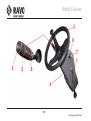
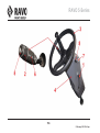
D. 7 Steering column . . . . . . . . . . . . . . . . . . . . . . . . . . . . . . . . . . . . . . . . . . . . . . . . . . . . . . . . . . .155
D. 7.1 Steering column adjustment (1) . . . . . . . . . . . . . . . . . . . . . . . . . . . . . . . . . . . . . . . . . . . . . . . . . . . . . . . . . . . . . . . . 155
D. 7.2 Steering column handle (6) . . . . . . . . . . . . . . . . . . . . . . . . . . . . . . . . . . . . . . . . . . . . . . . . . . . . . . . . . . . . . . . . . . . . 155
D. 7.3 Steering wheel (3) . . . . . . . . . . . . . . . . . . . . . . . . . . . . . . . . . . . . . . . . . . . . . . . . . . . . . . . . . . . . . . . . . . . . . . . . . . . . 157
D. 7.4 Ignition key switch (7). . . . . . . . . . . . . . . . . . . . . . . . . . . . . . . . . . . . . . . . . . . . . . . . . . . . . . . . . . . . . . . . . . . . . . . . . 157
D. 7.5 Driving direction switch (8) . . . . . . . . . . . . . . . . . . . . . . . . . . . . . . . . . . . . . . . . . . . . . . . . . . . . . . . . . . . . . . . . . . . . 159
D. 8 iSystem LED display panel . . . . . . . . . . . . . . . . . . . . . . . . . . . . . . . . . . . . . . . . . . . . . . . . . .161
D. 8.1 Hazard-lights switch . . . . . . . . . . . . . . . . . . . . . . . . . . . . . . . . . . . . . . . . . . . . . . . . . . . . . . . . . . . . . . . . . . . . . . . . . . 161
D. 8.2 Light switch . . . . . . . . . . . . . . . . . . . . . . . . . . . . . . . . . . . . . . . . . . . . . . . . . . . . . . . . . . . . . . . . . . . . . . . . . . . . . . . . . 161
D. 8.3 Beacon light switch . . . . . . . . . . . . . . . . . . . . . . . . . . . . . . . . . . . . . . . . . . . . . . . . . . . . . . . . . . . . . . . . . . . . . . . . . . 161
D. 8.4 Rear fog light . . . . . . . . . . . . . . . . . . . . . . . . . . . . . . . . . . . . . . . . . . . . . . . . . . . . . . . . . . . . . . . . . . . . . . . . . . . . . . . . 161
D. 8.5 Mirror heating switch (optional) . . . . . . . . . . . . . . . . . . . . . . . . . . . . . . . . . . . . . . . . . . . . . . . . . . . . . . . . . . . . . . . . 161
D. 8.6 Headlight height adjustment (ABS) . . . . . . . . . . . . . . . . . . . . . . . . . . . . . . . . . . . . . . . . . . . . . . . . . . . . . . . . . . . . . . 161
D. 9 Pedals . . . . . . . . . . . . . . . . . . . . . . . . . . . . . . . . . . . . . . . . . . . . . . . . . . . . . . . . . . . . . . . . . . .163
D. 9.1 Accelerator pedal . . . . . . . . . . . . . . . . . . . . . . . . . . . . . . . . . . . . . . . . . . . . . . . . . . . . . . . . . . . . . . . . . . . . . . . . . . . . 163
D. 9.2 Brake pedal . . . . . . . . . . . . . . . . . . . . . . . . . . . . . . . . . . . . . . . . . . . . . . . . . . . . . . . . . . . . . . . . . . . . . . . . . . . . . . . . . 163
D. 9.3 Foot switch . . . . . . . . . . . . . . . . . . . . . . . . . . . . . . . . . . . . . . . . . . . . . . . . . . . . . . . . . . . . . . . . . . . . . . . . . . . . . . . . . 163
D. 10 Door console . . . . . . . . . . . . . . . . . . . . . . . . . . . . . . . . . . . . . . . . . . . . . . . . . . . . . . . . . . . . .165
D. 10.1 Door handle . . . . . . . . . . . . . . . . . . . . . . . . . . . . . . . . . . . . . . . . . . . . . . . . . . . . . . . . . . . . . . . . . . . . . . . . . . . . . . . . 165
D. 10.2 Switch. . . . . . . . . . . . . . . . . . . . . . . . . . . . . . . . . . . . . . . . . . . . . . . . . . . . . . . . . . . . . . . . . . . . . . . . . . . . . . . . . . . . . 165
D. 10.3 Third brush button (option) . . . . . . . . . . . . . . . . . . . . . . . . . . . . . . . . . . . . . . . . . . . . . . . . . . . . . . . . . . . . . . . . . . . 165
D. 10.4 Gutter brush angle adjustment switch (option) . . . . . . . . . . . . . . . . . . . . . . . . . . . . . . . . . . . . . . . . . . . . . . . . . . . 165
10
5 February 2015 12:49 pm
RAVO 5-Series
D. 10.5 Switch, third brush (option) . . . . . . . . . . . . . . . . . . . . . . . . . . . . . . . . . . . . . . . . . . . . . . . . . . . . . . . . . . . . . . . . . .
D. 10.6 Joystick . . . . . . . . . . . . . . . . . . . . . . . . . . . . . . . . . . . . . . . . . . . . . . . . . . . . . . . . . . . . . . . . . . . . . . . . . . . . . . . . . . .
D. 10.7 Joystick, third brush (option) . . . . . . . . . . . . . . . . . . . . . . . . . . . . . . . . . . . . . . . . . . . . . . . . . . . . . . . . . . . . . . . . .
D. 10.8 Door console adjustment . . . . . . . . . . . . . . . . . . . . . . . . . . . . . . . . . . . . . . . . . . . . . . . . . . . . . . . . . . . . . . . . . . . .
165
167
167
167
D. 11 Heating and Air Conditioning . . . . . . . . . . . . . . . . . . . . . . . . . . . . . . . . . . . . . . . . . . . . . . .169
D. 11.1 Air conditioning knob . . . . . . . . . . . . . . . . . . . . . . . . . . . . . . . . . . . . . . . . . . . . . . . . . . . . . . . . . . . . . . . . . . . . . . .
D. 11.2 Recirculation knob . . . . . . . . . . . . . . . . . . . . . . . . . . . . . . . . . . . . . . . . . . . . . . . . . . . . . . . . . . . . . . . . . . . . . . . . . .
D. 11.3 Airflow selection knob . . . . . . . . . . . . . . . . . . . . . . . . . . . . . . . . . . . . . . . . . . . . . . . . . . . . . . . . . . . . . . . . . . . . . . .
D. 11.4 Temperature knob . . . . . . . . . . . . . . . . . . . . . . . . . . . . . . . . . . . . . . . . . . . . . . . . . . . . . . . . . . . . . . . . . . . . . . . . . .
D. 11.5 Heater fan knob . . . . . . . . . . . . . . . . . . . . . . . . . . . . . . . . . . . . . . . . . . . . . . . . . . . . . . . . . . . . . . . . . . . . . . . . . . . .
169
169
169
169
169
D. 12 Radio and interior lighting . . . . . . . . . . . . . . . . . . . . . . . . . . . . . . . . . . . . . . . . . . . . . . . . . .171
D. 12.1 Radio (1) . . . . . . . . . . . . . . . . . . . . . . . . . . . . . . . . . . . . . . . . . . . . . . . . . . . . . . . . . . . . . . . . . . . . . . . . . . . . . . . . . . 171
D. 12.2 Interior lighting (2) . . . . . . . . . . . . . . . . . . . . . . . . . . . . . . . . . . . . . . . . . . . . . . . . . . . . . . . . . . . . . . . . . . . . . . . . . . 171
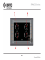
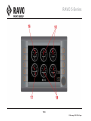
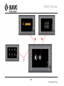
D. 13 Container remote control ST and CD . . . . . . . . . . . . . . . . . . . . . . . . . . . . . . . . . . . . . . . . .173
D. 13.1 Raise container button . . . . . . . . . . . . . . . . . . . . . . . . . . . . . . . . . . . . . . . . . . . . . . . . . . . . . . . . . . . . . . . . . . . . . .
D. 13.2 Lower container button . . . . . . . . . . . . . . . . . . . . . . . . . . . . . . . . . . . . . . . . . . . . . . . . . . . . . . . . . . . . . . . . . . . . . .
D. 13.3 Open container door/extend pusher button . . . . . . . . . . . . . . . . . . . . . . . . . . . . . . . . . . . . . . . . . . . . . . . . . . . . .
D. 13.4 Close container door/retract pusher button . . . . . . . . . . . . . . . . . . . . . . . . . . . . . . . . . . . . . . . . . . . . . . . . . . . . .
D. 13.5 Container emergency stop button . . . . . . . . . . . . . . . . . . . . . . . . . . . . . . . . . . . . . . . . . . . . . . . . . . . . . . . . . . . . .
D. 13.6 Container emergency stop reset . . . . . . . . . . . . . . . . . . . . . . . . . . . . . . . . . . . . . . . . . . . . . . . . . . . . . . . . . . . . . .
173
173
173
173
173
173
D. 14 Driver's seat. . . . . . . . . . . . . . . . . . . . . . . . . . . . . . . . . . . . . . . . . . . . . . . . . . . . . . . . . . . . . .175
D. 14.1 Adjusting the angle of the back of the seat . . . . . . . . . . . . . . . . . . . . . . . . . . . . . . . . . . . . . . . . . . . . . . . . . . . . . .
D. 14.2 Springs . . . . . . . . . . . . . . . . . . . . . . . . . . . . . . . . . . . . . . . . . . . . . . . . . . . . . . . . . . . . . . . . . . . . . . . . . . . . . . . . . . .
D. 14.3 Distance to the steering wheel and the pedals . . . . . . . . . . . . . . . . . . . . . . . . . . . . . . . . . . . . . . . . . . . . . . . . . . .
D. 14.4 Height of the seat . . . . . . . . . . . . . . . . . . . . . . . . . . . . . . . . . . . . . . . . . . . . . . . . . . . . . . . . . . . . . . . . . . . . . . . . . . .
D. 14.5 Adjusting the lumbar support of the chair. . . . . . . . . . . . . . . . . . . . . . . . . . . . . . . . . . . . . . . . . . . . . . . . . . . . . . .
11
5 February 2015 12:49 pm
175
175
175
175
175
RAVO 5-Series
D. 15 Climate control unit (option) . . . . . . . . . . . . . . . . . . . . . . . . . . . . . . . . . . . . . . . . . . . . . . . .177
D. 15.1 Fan speed control . . . . . . . . . . . . . . . . . . . . . . . . . . . . . . . . . . . . . . . . . . . . . . . . . . . . . . . . . . . . . . . . . . . . . . . . . . . 177
D. 15.2 Recirculation button . . . . . . . . . . . . . . . . . . . . . . . . . . . . . . . . . . . . . . . . . . . . . . . . . . . . . . . . . . . . . . . . . . . . . . . . . 177
D. 15.3 Temperature controller. . . . . . . . . . . . . . . . . . . . . . . . . . . . . . . . . . . . . . . . . . . . . . . . . . . . . . . . . . . . . . . . . . . . . . . 177
D. 15.4 Air conditioning button . . . . . . . . . . . . . . . . . . . . . . . . . . . . . . . . . . . . . . . . . . . . . . . . . . . . . . . . . . . . . . . . . . . . . . 179
D. 15.5 Airflow selection knob . . . . . . . . . . . . . . . . . . . . . . . . . . . . . . . . . . . . . . . . . . . . . . . . . . . . . . . . . . . . . . . . . . . . . . . 179
D. 15.6 Defrost/demist function . . . . . . . . . . . . . . . . . . . . . . . . . . . . . . . . . . . . . . . . . . . . . . . . . . . . . . . . . . . . . . . . . . . . . . 179
D. 16 Parking brake . . . . . . . . . . . . . . . . . . . . . . . . . . . . . . . . . . . . . . . . . . . . . . . . . . . . . . . . . . . .181
D. 16.1 Disengaging the parking brake . . . . . . . . . . . . . . . . . . . . . . . . . . . . . . . . . . . . . . . . . . . . . . . . . . . . . . . . . . . . . . . . 181
D. 16.2 Engaging the parking brake. . . . . . . . . . . . . . . . . . . . . . . . . . . . . . . . . . . . . . . . . . . . . . . . . . . . . . . . . . . . . . . . . . . 181
D. 17 Suction tube inspection hatch. . . . . . . . . . . . . . . . . . . . . . . . . . . . . . . . . . . . . . . . . . . . . . .183
D. 17.1 Suction tube tunnel inspection hatch . . . . . . . . . . . . . . . . . . . . . . . . . . . . . . . . . . . . . . . . . . . . . . . . . . . . . . . . . . . 183
D. 17.2 Suction tube inspection hatch. . . . . . . . . . . . . . . . . . . . . . . . . . . . . . . . . . . . . . . . . . . . . . . . . . . . . . . . . . . . . . . . . 183
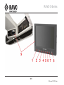
D. 18 Positive battery terminal switch . . . . . . . . . . . . . . . . . . . . . . . . . . . . . . . . . . . . . . . . . . . . .185
D. 18.1 Switching off the positive battery terminal switch . . . . . . . . . . . . . . . . . . . . . . . . . . . . . . . . . . . . . . . . . . . . . . . . 185
D. 18.2 Switching on the positive battery terminal switch. . . . . . . . . . . . . . . . . . . . . . . . . . . . . . . . . . . . . . . . . . . . . . . . . 185
E. STARTING AND DRIVING . . . . . . . . . . . . . . . . . . . . . . . . . . . . . . . . . . . 187
E. 1 Starting the Engine . . . . . . . . . . . . . . . . . . . . . . . . . . . . . . . . . . . . . . . . . . . . . . . . . . . . . . . . .189
E. 1.1 Starting: . . . . . . . . . . . . . . . . . . . . . . . . . . . . . . . . . . . . . . . . . . . . . . . . . . . . . . . . . . . . . . . . . . . . . . . . . . . . . . . . . . . . 189
E. 2 Drive . . . . . . . . . . . . . . . . . . . . . . . . . . . . . . . . . . . . . . . . . . . . . . . . . . . . . . . . . . . . . . . . . . . . .189
E. 3 Brake . . . . . . . . . . . . . . . . . . . . . . . . . . . . . . . . . . . . . . . . . . . . . . . . . . . . . . . . . . . . . . . . . . . .191
E. 3.1 Hydraulic brakes . . . . . . . . . . . . . . . . . . . . . . . . . . . . . . . . . . . . . . . . . . . . . . . . . . . . . . . . . . . . . . . . . . . . . . . . . . . . . 191
E. 3.2 Footbrake . . . . . . . . . . . . . . . . . . . . . . . . . . . . . . . . . . . . . . . . . . . . . . . . . . . . . . . . . . . . . . . . . . . . . . . . . . . . . . . . . . . 191
E. 3.3 Emergency brake/parking brake . . . . . . . . . . . . . . . . . . . . . . . . . . . . . . . . . . . . . . . . . . . . . . . . . . . . . . . . . . . . . . . . 191
12
5 February 2015 12:49 pm
RAVO 5-Series
E. 4 Sweeping . . . . . . . . . . . . . . . . . . . . . . . . . . . . . . . . . . . . . . . . . . . . . . . . . . . . . . . . . . . . . . . . .193
E. 5 Stopping sweeping briefly . . . . . . . . . . . . . . . . . . . . . . . . . . . . . . . . . . . . . . . . . . . . . . . . . . .193
E. 5.1 Stopping for a short time: . . . . . . . . . . . . . . . . . . . . . . . . . . . . . . . . . . . . . . . . . . . . . . . . . . . . . . . . . . . . . . . . . . . . . 193
E. 5.2 Resume: . . . . . . . . . . . . . . . . . . . . . . . . . . . . . . . . . . . . . . . . . . . . . . . . . . . . . . . . . . . . . . . . . . . . . . . . . . . . . . . . . . . 193
E. 6 Stopping sweeping for a longer time . . . . . . . . . . . . . . . . . . . . . . . . . . . . . . . . . . . . . . . . . .195
E. 6.1 Stop for a longer time: . . . . . . . . . . . . . . . . . . . . . . . . . . . . . . . . . . . . . . . . . . . . . . . . . . . . . . . . . . . . . . . . . . . . . . . . 195
E. 6.2 Resume: . . . . . . . . . . . . . . . . . . . . . . . . . . . . . . . . . . . . . . . . . . . . . . . . . . . . . . . . . . . . . . . . . . . . . . . . . . . . . . . . . . . 195
E. 7 Opening cabin door open while sweeping . . . . . . . . . . . . . . . . . . . . . . . . . . . . . . . . . . . . . .195
E. 7.1 Resuming sweeping after opening cabin door: . . . . . . . . . . . . . . . . . . . . . . . . . . . . . . . . . . . . . . . . . . . . . . . . . . . 195
E. 8 Dumping ST container . . . . . . . . . . . . . . . . . . . . . . . . . . . . . . . . . . . . . . . . . . . . . . . . . . . . . .197
E. 8.1 Dumping:. . . . . . . . . . . . . . . . . . . . . . . . . . . . . . . . . . . . . . . . . . . . . . . . . . . . . . . . . . . . . . . . . . . . . . . . . . . . . . . . . . . 197
E. 9 Dumping CD container . . . . . . . . . . . . . . . . . . . . . . . . . . . . . . . . . . . . . . . . . . . . . . . . . . . . . .199
E. 9.1 Dumping:. . . . . . . . . . . . . . . . . . . . . . . . . . . . . . . . . . . . . . . . . . . . . . . . . . . . . . . . . . . . . . . . . . . . . . . . . . . . . . . . . . . 199
E. 10 Instructions and tips for sweeping . . . . . . . . . . . . . . . . . . . . . . . . . . . . . . . . . . . . . . . . . . .201
E. 10.1 Sweeping a right-angled inner corner. . . . . . . . . . . . . . . . . . . . . . . . . . . . . . . . . . . . . . . . . . . . . . . . . . . . . . . . . . . 203
E. 10.2 Optimum sweeping speed . . . . . . . . . . . . . . . . . . . . . . . . . . . . . . . . . . . . . . . . . . . . . . . . . . . . . . . . . . . . . . . . . . . . 204
E. 11 Sweeping with the third brush (option) . . . . . . . . . . . . . . . . . . . . . . . . . . . . . . . . . . . . . . .207
E. 11.1 Implementation: . . . . . . . . . . . . . . . . . . . . . . . . . . . . . . . . . . . . . . . . . . . . . . . . . . . . . . . . . . . . . . . . . . . . . . . . . . . . 207
E. 11.2 Retraction:. . . . . . . . . . . . . . . . . . . . . . . . . . . . . . . . . . . . . . . . . . . . . . . . . . . . . . . . . . . . . . . . . . . . . . . . . . . . . . . . . 207
E. 12 Opening cabin door while sweeping with third brush. . . . . . . . . . . . . . . . . . . . . . . . . . . .209
E. 12.1 Resuming sweeping with third brush after opening cabin door: . . . . . . . . . . . . . . . . . . . . . . . . . . . . . . . . . . . . 209
E. 13 Third brush rapid replacement system (option) . . . . . . . . . . . . . . . . . . . . . . . . . . . . . . . .211
E. 13.1 Uninstalling the third brush using the rapid replacement system: . . . . . . . . . . . . . . . . . . . . . . . . . . . . . . . . . . . 211
E. 13.2 Installing the third brush using the rapid replacement system: . . . . . . . . . . . . . . . . . . . . . . . . . . . . . . . . . . . . . 213
E. 14 Working with the high pressure water pump (optional) . . . . . . . . . . . . . . . . . . . . . . . . . .215
E. 14.1 To operate: . . . . . . . . . . . . . . . . . . . . . . . . . . . . . . . . . . . . . . . . . . . . . . . . . . . . . . . . . . . . . . . . . . . . . . . . . . . . . . . . 215
13
5 February 2015 12:49 pm
RAVO 5-Series
E. 14.2 Setting the pressure for the high pressure water pump: . . . . . . . . . . . . . . . . . . . . . . . . . . . . . . . . . . . . . . . . . . . 215
E. 15 Working with the swasher (option) . . . . . . . . . . . . . . . . . . . . . . . . . . . . . . . . . . . . . . . . . . .217
E. 15.1 Implementation:. . . . . . . . . . . . . . . . . . . . . . . . . . . . . . . . . . . . . . . . . . . . . . . . . . . . . . . . . . . . . . . . . . . . . . . . . . . . . 217
E. 15.2 High-pressure water pump pressure settings:. . . . . . . . . . . . . . . . . . . . . . . . . . . . . . . . . . . . . . . . . . . . . . . . . . . . 217
E. 16 Working with the leaf-suction arm - drain-suction arm (option). . . . . . . . . . . . . . . . . . . .219
E. 16.1 Implementation:. . . . . . . . . . . . . . . . . . . . . . . . . . . . . . . . . . . . . . . . . . . . . . . . . . . . . . . . . . . . . . . . . . . . . . . . . . . . . 219
E. 17 Water recirculation (option) . . . . . . . . . . . . . . . . . . . . . . . . . . . . . . . . . . . . . . . . . . . . . . . . .221
E. 17.1 Implementation:. . . . . . . . . . . . . . . . . . . . . . . . . . . . . . . . . . . . . . . . . . . . . . . . . . . . . . . . . . . . . . . . . . . . . . . . . . . . . 221
E. 17.2 Remove water from the container: . . . . . . . . . . . . . . . . . . . . . . . . . . . . . . . . . . . . . . . . . . . . . . . . . . . . . . . . . . . . . 221
E. 17.3 Cleaning the filter:. . . . . . . . . . . . . . . . . . . . . . . . . . . . . . . . . . . . . . . . . . . . . . . . . . . . . . . . . . . . . . . . . . . . . . . . . . . 223
E. 17.4 Rinse through the pipes: . . . . . . . . . . . . . . . . . . . . . . . . . . . . . . . . . . . . . . . . . . . . . . . . . . . . . . . . . . . . . . . . . . . . . 223
E. 18 Camera system . . . . . . . . . . . . . . . . . . . . . . . . . . . . . . . . . . . . . . . . . . . . . . . . . . . . . . . . . . .225
E. 18.1 Camera system functions: . . . . . . . . . . . . . . . . . . . . . . . . . . . . . . . . . . . . . . . . . . . . . . . . . . . . . . . . . . . . . . . . . . . . 225
E. 19 Easy liftable grid . . . . . . . . . . . . . . . . . . . . . . . . . . . . . . . . . . . . . . . . . . . . . . . . . . . . . . . . . .227
E. 19.1 Operation of easy liftable grid: . . . . . . . . . . . . . . . . . . . . . . . . . . . . . . . . . . . . . . . . . . . . . . . . . . . . . . . . . . . . . . . . 227
F. SERVICE/MAINTENANCE . . . . . . . . . . . . . . . . . . . . . . . . . . . . . . . . . . . 229
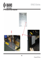
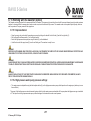
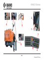
F. 1 Adjustment of sweeper unit suction head . . . . . . . . . . . . . . . . . . . . . . . . . . . . . . . . . . . . . .231
F. 1.1 Suction head levelling. . . . . . . . . . . . . . . . . . . . . . . . . . . . . . . . . . . . . . . . . . . . . . . . . . . . . . . . . . . . . . . . . . . . . . . . . 231
F. 1.2 Road surface clearance . . . . . . . . . . . . . . . . . . . . . . . . . . . . . . . . . . . . . . . . . . . . . . . . . . . . . . . . . . . . . . . . . . . . . . . 231
F. 1.3 Suction head rubbers . . . . . . . . . . . . . . . . . . . . . . . . . . . . . . . . . . . . . . . . . . . . . . . . . . . . . . . . . . . . . . . . . . . . . . . . . 231
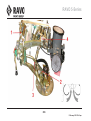
F. 2 Adjusting the brushes of the sweeper . . . . . . . . . . . . . . . . . . . . . . . . . . . . . . . . . . . . . . . . .233
F. 2.1 Brush pressure . . . . . . . . . . . . . . . . . . . . . . . . . . . . . . . . . . . . . . . . . . . . . . . . . . . . . . . . . . . . . . . . . . . . . . . . . . . . . . 233
F. 2.2 Forward angle of the brushes . . . . . . . . . . . . . . . . . . . . . . . . . . . . . . . . . . . . . . . . . . . . . . . . . . . . . . . . . . . . . . . . . . 235
F. 2.3 Sideways angle of the brush . . . . . . . . . . . . . . . . . . . . . . . . . . . . . . . . . . . . . . . . . . . . . . . . . . . . . . . . . . . . . . . . . . . 235
14
5 February 2015 12:49 pm
RAVO 5-Series
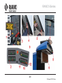
F. 2.4 Distance to the suction nozzle . . . . . . . . . . . . . . . . . . . . . . . . . . . . . . . . . . . . . . . . . . . . . . . . . . . . . . . . . . . . . . . . . 237
F. 3 Quickly changing sweeping brushes . . . . . . . . . . . . . . . . . . . . . . . . . . . . . . . . . . . . . . . . . .239
F. 3.1 Removing brush: . . . . . . . . . . . . . . . . . . . . . . . . . . . . . . . . . . . . . . . . . . . . . . . . . . . . . . . . . . . . . . . . . . . . . . . . . . . . 239
F. 3.2 Fitting brush:. . . . . . . . . . . . . . . . . . . . . . . . . . . . . . . . . . . . . . . . . . . . . . . . . . . . . . . . . . . . . . . . . . . . . . . . . . . . . . . . 239
F. 4 Daily sprayer maintenance. . . . . . . . . . . . . . . . . . . . . . . . . . . . . . . . . . . . . . . . . . . . . . . . . . .241
F. 4.1 Cleaning suction tube, suction nozzle and suction nozzle sprayers . . . . . . . . . . . . . . . . . . . . . . . . . . . . . . . . . . 241
F. 4.2 Cleaning brush sprayers . . . . . . . . . . . . . . . . . . . . . . . . . . . . . . . . . . . . . . . . . . . . . . . . . . . . . . . . . . . . . . . . . . . . . . 241
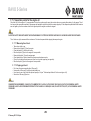
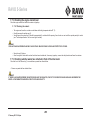
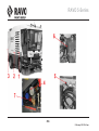
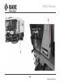
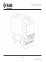
F. 5 Cleaning sweeper container. . . . . . . . . . . . . . . . . . . . . . . . . . . . . . . . . . . . . . . . . . . . . . . . . .243
F. 5.1 Cleaning suction tube, suction nozzle (1) . . . . . . . . . . . . . . . . . . . . . . . . . . . . . . . . . . . . . . . . . . . . . . . . . . . . . . . .
F. 5.2 Cleaning container (2) . . . . . . . . . . . . . . . . . . . . . . . . . . . . . . . . . . . . . . . . . . . . . . . . . . . . . . . . . . . . . . . . . . . . . . . .
F. 5.3 Cleaning the first interior grid (3) . . . . . . . . . . . . . . . . . . . . . . . . . . . . . . . . . . . . . . . . . . . . . . . . . . . . . . . . . . . . . . .
F. 5.4 Cleaning second interior grid (4) . . . . . . . . . . . . . . . . . . . . . . . . . . . . . . . . . . . . . . . . . . . . . . . . . . . . . . . . . . . . . . .
F. 5.5 Cleaning pusher (5) (only for CD version) . . . . . . . . . . . . . . . . . . . . . . . . . . . . . . . . . . . . . . . . . . . . . . . . . . . . . . . .
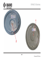
F. 5.6 Cleaning fan (6). . . . . . . . . . . . . . . . . . . . . . . . . . . . . . . . . . . . . . . . . . . . . . . . . . . . . . . . . . . . . . . . . . . . . . . . . . . . . .
243
243
243
243
243
245
F. 6 Cleaning the outside of the machine. . . . . . . . . . . . . . . . . . . . . . . . . . . . . . . . . . . . . . . . . . .247
F. 6.1 Cleaning. . . . . . . . . . . . . . . . . . . . . . . . . . . . . . . . . . . . . . . . . . . . . . . . . . . . . . . . . . . . . . . . . . . . . . . . . . . . . . . . . . . . 247
F. 7 Daily inspection points . . . . . . . . . . . . . . . . . . . . . . . . . . . . . . . . . . . . . . . . . . . . . . . . . . . . . .248
F. 7.1 General information . . . . . . . . . . . . . . . . . . . . . . . . . . . . . . . . . . . . . . . . . . . . . . . . . . . . . . . . . . . . . . . . . . . . . . . . . .
F. 7.2 Checking the fuel level. . . . . . . . . . . . . . . . . . . . . . . . . . . . . . . . . . . . . . . . . . . . . . . . . . . . . . . . . . . . . . . . . . . . . . . .
F. 7.3 Checking the lighting . . . . . . . . . . . . . . . . . . . . . . . . . . . . . . . . . . . . . . . . . . . . . . . . . . . . . . . . . . . . . . . . . . . . . . . . .
F. 7.4 Checking the tyre pressure . . . . . . . . . . . . . . . . . . . . . . . . . . . . . . . . . . . . . . . . . . . . . . . . . . . . . . . . . . . . . . . . . . . .
F. 7.5 Checking the level of water in the spray water tank . . . . . . . . . . . . . . . . . . . . . . . . . . . . . . . . . . . . . . . . . . . . . . . .
F. 7.6 Checking the AdBlue tank level . . . . . . . . . . . . . . . . . . . . . . . . . . . . . . . . . . . . . . . . . . . . . . . . . . . . . . . . . . . . . . . .
F. 7.7 Inspection points for the engine oil . . . . . . . . . . . . . . . . . . . . . . . . . . . . . . . . . . . . . . . . . . . . . . . . . . . . . . . . . . . . .
F. 7.8 Checking the engine coolant level . . . . . . . . . . . . . . . . . . . . . . . . . . . . . . . . . . . . . . . . . . . . . . . . . . . . . . . . . . . . . .
F. 7.9 Checking whether waste has collected in front of the intercooler . . . . . . . . . . . . . . . . . . . . . . . . . . . . . . . . . . . .
F. 7.10 Checking the hydraulic system. . . . . . . . . . . . . . . . . . . . . . . . . . . . . . . . . . . . . . . . . . . . . . . . . . . . . . . . . . . . . . . .
15
5 February 2015 12:49 pm
248
248
248
248
249
251
253
255
255
257
RAVO 5-Series
F. 7.11 Topping up the spray water . . . . . . . . . . . . . . . . . . . . . . . . . . . . . . . . . . . . . . . . . . . . . . . . . . . . . . . . . . . . . . . . . . . 257
F. 7.12 Checking the container. . . . . . . . . . . . . . . . . . . . . . . . . . . . . . . . . . . . . . . . . . . . . . . . . . . . . . . . . . . . . . . . . . . . . . . 257
F. 7.13 Checking the ATF system. . . . . . . . . . . . . . . . . . . . . . . . . . . . . . . . . . . . . . . . . . . . . . . . . . . . . . . . . . . . . . . . . . . . . 257
F. 7.14 Topping up the washer fluid: . . . . . . . . . . . . . . . . . . . . . . . . . . . . . . . . . . . . . . . . . . . . . . . . . . . . . . . . . . . . . . . . . . 259
F. 7.15 Check the oil level of the high-pressure water pump (option) . . . . . . . . . . . . . . . . . . . . . . . . . . . . . . . . . . . . . . . 261
F. 8 Changing the light bulbs . . . . . . . . . . . . . . . . . . . . . . . . . . . . . . . . . . . . . . . . . . . . . . . . . . . .263
F. 8.1 Main beam headlight (1) . . . . . . . . . . . . . . . . . . . . . . . . . . . . . . . . . . . . . . . . . . . . . . . . . . . . . . . . . . . . . . . . . . . . . . . 263
F. 8.2 Dipped beam headlight (2) . . . . . . . . . . . . . . . . . . . . . . . . . . . . . . . . . . . . . . . . . . . . . . . . . . . . . . . . . . . . . . . . . . . . . 263
F. 8.3 Direction indicator lights front (3) . . . . . . . . . . . . . . . . . . . . . . . . . . . . . . . . . . . . . . . . . . . . . . . . . . . . . . . . . . . . . . . 263
F. 8.4 Parking lights (4) . . . . . . . . . . . . . . . . . . . . . . . . . . . . . . . . . . . . . . . . . . . . . . . . . . . . . . . . . . . . . . . . . . . . . . . . . . . . . 265
F. 8.5 Indicator lights on the side of the cabin (5) . . . . . . . . . . . . . . . . . . . . . . . . . . . . . . . . . . . . . . . . . . . . . . . . . . . . . . . 265
F. 8.6 Brush light (6) . . . . . . . . . . . . . . . . . . . . . . . . . . . . . . . . . . . . . . . . . . . . . . . . . . . . . . . . . . . . . . . . . . . . . . . . . . . . . . . 265
F. 8.7 Front and rear beacon lights (7). . . . . . . . . . . . . . . . . . . . . . . . . . . . . . . . . . . . . . . . . . . . . . . . . . . . . . . . . . . . . . . . . 265
F. 8.8 Rear indicator lights (8) . . . . . . . . . . . . . . . . . . . . . . . . . . . . . . . . . . . . . . . . . . . . . . . . . . . . . . . . . . . . . . . . . . . . . . . 267
F. 8.9 Brake light (9). . . . . . . . . . . . . . . . . . . . . . . . . . . . . . . . . . . . . . . . . . . . . . . . . . . . . . . . . . . . . . . . . . . . . . . . . . . . . . . . 267
F. 8.10 Tail light (10) . . . . . . . . . . . . . . . . . . . . . . . . . . . . . . . . . . . . . . . . . . . . . . . . . . . . . . . . . . . . . . . . . . . . . . . . . . . . . . . 267
F. 8.11 Reverse light (11) only on 560 . . . . . . . . . . . . . . . . . . . . . . . . . . . . . . . . . . . . . . . . . . . . . . . . . . . . . . . . . . . . . . . . . 267
F. 8.12 Rear fog light (12) only on 560 . . . . . . . . . . . . . . . . . . . . . . . . . . . . . . . . . . . . . . . . . . . . . . . . . . . . . . . . . . . . . . . . . 267
F. 8.13 Reverse light (13) only connected on 540. . . . . . . . . . . . . . . . . . . . . . . . . . . . . . . . . . . . . . . . . . . . . . . . . . . . . . . . 269
F. 8.14 Rear fog light (14) only connected on 540 . . . . . . . . . . . . . . . . . . . . . . . . . . . . . . . . . . . . . . . . . . . . . . . . . . . . . . . 269
F. 9 Changing a wheel . . . . . . . . . . . . . . . . . . . . . . . . . . . . . . . . . . . . . . . . . . . . . . . . . . . . . . . . . .271
F. 9.1 Changing a wheel . . . . . . . . . . . . . . . . . . . . . . . . . . . . . . . . . . . . . . . . . . . . . . . . . . . . . . . . . . . . . . . . . . . . . . . . . . . . 271
F. 10 Towing the vehicle . . . . . . . . . . . . . . . . . . . . . . . . . . . . . . . . . . . . . . . . . . . . . . . . . . . . . . . .273
F. 10.1 Towing . . . . . . . . . . . . . . . . . . . . . . . . . . . . . . . . . . . . . . . . . . . . . . . . . . . . . . . . . . . . . . . . . . . . . . . . . . . . . . . . . . . . 273
F. 11 Raising the hopper whilst the engine is turned off . . . . . . . . . . . . . . . . . . . . . . . . . . . . . .275
F. 11.1 Raising the hopper using the emergency hand pump. . . . . . . . . . . . . . . . . . . . . . . . . . . . . . . . . . . . . . . . . . . . . . 275
F. 11.2 Raising and lowering the container using the emergency hand pump (not recommended) . . . . . . . . . . . . . . . 275
16
5 February 2015 12:49 pm
RAVO 5-Series
F. 12 Deactivating the parking brake . . . . . . . . . . . . . . . . . . . . . . . . . . . . . . . . . . . . . . . . . . . . . .277
F. 12.1 Disconnecting parking brake . . . . . . . . . . . . . . . . . . . . . . . . . . . . . . . . . . . . . . . . . . . . . . . . . . . . . . . . . . . . . . . . . 277
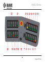
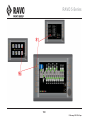
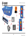
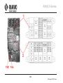
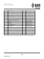
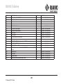
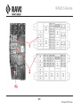
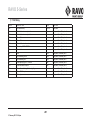
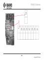
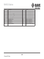
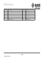
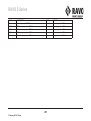
F. 13 Fuses/Relays . . . . . . . . . . . . . . . . . . . . . . . . . . . . . . . . . . . . . . . . . . . . . . . . . . . . . . . . . . . . .279
F. 13.1 Fuse/relay box. . . . . . . . . . . . . . . . . . . . . . . . . . . . . . . . . . . . . . . . . . . . . . . . . . . . . . . . . . . . . . . . . . . . . . . . . . . . . . 279
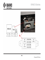
F. 13.2 Relay . . . . . . . . . . . . . . . . . . . . . . . . . . . . . . . . . . . . . . . . . . . . . . . . . . . . . . . . . . . . . . . . . . . . . . . . . . . . . . . . . . . . . 291
F. 14 Maintenance of air conditioning unit. . . . . . . . . . . . . . . . . . . . . . . . . . . . . . . . . . . . . . . . . .298
F. 14.1 Checking the drive belt . . . . . . . . . . . . . . . . . . . . . . . . . . . . . . . . . . . . . . . . . . . . . . . . . . . . . . . . . . . . . . . . . . . . . . 298
F. 14.2 Annual inspection. . . . . . . . . . . . . . . . . . . . . . . . . . . . . . . . . . . . . . . . . . . . . . . . . . . . . . . . . . . . . . . . . . . . . . . . . . . 298
F. 15 Sub zero operation . . . . . . . . . . . . . . . . . . . . . . . . . . . . . . . . . . . . . . . . . . . . . . . . . . . . . . . .301
F. 15.1 If sub zero temperatures are expected . . . . . . . . . . . . . . . . . . . . . . . . . . . . . . . . . . . . . . . . . . . . . . . . . . . . . . . . . .
F. 15.2 Drain the spray water tank (option 1) . . . . . . . . . . . . . . . . . . . . . . . . . . . . . . . . . . . . . . . . . . . . . . . . . . . . . . . . . . .
F. 15.3 Drain the spray water tank (option 2) . . . . . . . . . . . . . . . . . . . . . . . . . . . . . . . . . . . . . . . . . . . . . . . . . . . . . . . . . . .
F. 15.4 What to do after a period of frost . . . . . . . . . . . . . . . . . . . . . . . . . . . . . . . . . . . . . . . . . . . . . . . . . . . . . . . . . . . . . .
301
301
301
303
F. 16 Lubrication frequency for manual lubrication . . . . . . . . . . . . . . . . . . . . . . . . . . . . . . . . . .305
F. 17 Spraywater fine-dirt filter . . . . . . . . . . . . . . . . . . . . . . . . . . . . . . . . . . . . . . . . . . . . . . . . . . .307
F. 17.1 Cleaning/replacing the spraywater fine-dirt filter . . . . . . . . . . . . . . . . . . . . . . . . . . . . . . . . . . . . . . . . . . . . . . . . . 307
17
5 February 2015 12:49 pm
RAVO 5-Series
18
5 February 2015 12:49 pm
RAVO 5-Series
A. TECHNICAL SPECIFICATIONS
19
5 February 2015 12:49 pm
RAVO 5-Series
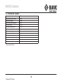
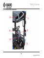
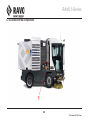
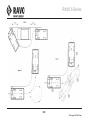
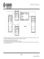
A. 1 Machine dimensions
Length
4525 mm
Width excl. mirrors
1805 mm
Width incl. mirrors
2280 mm
Sweeping width
2200 mm/2000 option
Height
2460 mm ST / 2460 mm CD / 2630 STH
A. 2 Machine weight
Empty weight on front axle
3080 kg ST / 3100 kg STH / 2980 kg CD
Empty weight on rear axle
2900 kg ST / 2930 kg STH / 3260 kg CD
Total empty weight
5980 kg ST / 6030 kg STH / 6240kg CD
Max. weight on front axle
see CE mark
Max. weight on rear axle
see CE mark
Max. weight
see CE mark
Load capacity
5130 kg ST / 5130 kg STH / 4870 kg CD
A. 3 Container
Tipping method
Tipping/58° ST/STH / Lifting/ejection CD
Operation
Hydraulic
Capacity
3.5 m3 ST/3.3 m3 CD/4.3 m3 STH
Tipping height
850 mm ST/1550 mm CD
Safety
Support in container door and below the container
20
5 February 2015 12:49 pm
RAVO 5-Series
A. 4 TIER3 engine
Make
Iveco
Type
N45 ENTX 21.00 / F4HE9484A
Diesel injection system
Common Rail – Electronic diesel control
High-pressure fuel pump type
Bosch CP 3
Number of cylinders
4
Total stroke volume (cc)
4485
Diameter & stroke (mm)
104 x 132
Compression ratio
16.5 : 1
PTO transmission ratio (PTO/engine)
1.03
Maximum torque (Nm)
560 @ 1400 rpm
Power (kW)
104 (141 hp) @ 2200 rpm
Specific fuel consumption (g/kWh)
205
Type of fuel
Standard diesel oil in accordance with EN 590
Engine-oil viscosity
15W40 Spec. MUIL-L-2104C/D (API CF-4/CF/CE)
Crankcase capacity (litre)
11.5 (incl. engine oil filter)
Coolant
Coolant to -40 °C
Coolant reservoir capacity (litres)
± 23
Supercharging
Turbo compressor with intercooler
Emission value/Standard value (g/kWh)
CO
1.30 / 5.00
NOx + HC
3.79 / 4.00
Particulates
0.189 / 0.300
Engine emission level
Tier 3 / Stage IIIA, dir.2004/26/EC
21
5 February 2015 12:49 pm
RAVO 5-Series
A. 5 EURO5 engine
Make
Iveco
Type
N40ENT526.00 / F4AE3481D*S
Diesel injection system
Common Rail – Electronic diesel control
High-pressure fuel pump type
Bosch CP 3.3
Number of cylinders
4
Total stroke volume (cc)
3920
Diameter & stroke (mm)
102 x 120
Compression ratio
17 : 1
PTO transmission ratio (PTO/engine)
1.03
Maximum torque (Nm)
535 @ 1250 rpm
Power (kW)
118 (160 hp) @ 2700 rpm
Specific fuel consumption (g/kWh)
201
Type of fuel
Standard diesel oil in accordance with EN 590
Engine-oil viscosity
15W40 Spec. ACEA E3 - E5 and API CF - CH4
Crankcase capacity (litre)
10.5 (incl. engine oil filter)
Coolant
Coolant to -40 °C
Coolant reservoir capacity (litres)
± 23
Supercharging
Turbo compressor with intercooler
Emission value/Standard value (g/kWh)
CO
0.55 / 1.5
HC
0.021 / 0.46
NOx
1.176 / 3.5
Particulates
0.018 / 0.02
Engine emission level
Euro 5, dir.2005/55/EC & 2006/51/EC by means of SCR
and Urea (AdBlue) injection
22
5 February 2015 12:49 pm
RAVO 5-Series
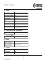
A. 6 Fan
Drive
Hydraulic
Fan diameter
720 mm
Number of blades
10
Fan capacity
170 m3/min (10.200 m3/h)
Location
Container roof
A. 7 Sweeper unit
Operation
Hydraulic with joystick
Brush diameter
900 mm (750 mm optional)
Brush speed
0 - 165 rpm (adjustable)
Number of brushes
2 (third brush optional)
Suction head dimensions
120 x 630 mm
Suction duct diameter
225 mm
A. 8 Water system
Operation
Electric
Tank capacity TIER3
540 litres
Tank capacity EURO5
500 litres
Max. pump capacity
11.5 litres/min. at 2 bar
Pump
Mechanical water ring pump
Sprayer positions
Brushes, suction duct, suction head, (leaf suction, third brush optional)
A. 9 Drive
Transmission
Hydrostatic continuously variable
Traction
Via hydraulic pump and two wheel motors with planetary hub reduction
Hub reduction oil
2.5 litres Texaco MULTIGEAR 80W-140
Differential
Hydraulic
23
5 February 2015 12:49 pm
RAVO 5-Series
A. 10 Front axle and suspension
Type
McPherson hydro pneumatic suspension
Height adjustment
Electronically via sensors
A. 11 Brake system
System
Disk brakes for rear drum brakes Hydraulically operated
via ATF system
Brake shoe make
Front: Wabco/Rear: Ferrodo
Dynamics
Hydrostatic brakes via the transmission when accelerator
is released
Parking brake
On the rear wheels. Parking brake is spring loaded and
lifted hydraulically. The parking brake is active when the
machine is switched off (after the system depressurises).
A. 12 Tyres
Front tyre make
Bridgestone, R168 215/75 R17.5 135/133 J
Rear tyre make
Bridgestone, 215/75 R17.5 126/124 M dual
Turning circle
3730 mm
Wheelbase
1816 mm
Tyre pressure
front: 8.5 bar/rear: 7.1 bar
A. 13 Electrical system
Voltage
24 V
Battery
2 x 12 V, 72 Ah in series, maintenance-free battery
Generator
28 V, 90 A
Radio
12 V (via converter)
Lights
24 V
24
5 February 2015 12:49 pm
RAVO 5-Series
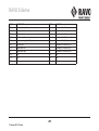
A. 14 Hydraulic system
Driving pump capacity
105 l/min
Driving pump operating pressure
420 bar
Booster pump capacity
22 l/min
Booster pump operating pressure
50 bar
Fan pump capacity
75 l/min
Fan pump operating pressure
175 bar
Brush pump capacity
19 l/min
Brush pump operating pressure
175 bar
Control pump capacity
22 l/min
Control pump operating pressure
150 bar
Battery filler system pump capacity
6 l/min
Brush motor operating pressure
165 bar max.
Fan motor operating pressure
175 bar
* Pump output at 1000 rpm.
25
5 February 2015 12:49 pm
RAVO 5-Series
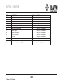
A. 15 Hydraulic system
Suction valve operating pressure
175 bar
Operating pressure of driving motors
420 bar
Operating pressure of suction head lift
175 bar
Operating pressure of container cylinder
175 bar
Operating pressure of brush lift
175 bar
Operating pressure of brush swivel
175 bar
Operating pressure of container door cylinder
175 bar
Operating pressure of battery filler system
175 bar
Brake system operating pressure
140 bar
Manual container tilt
Hand pump
Hydraulic fluid tank location
Incorporated in frame
ATF fluid tank location
Engine compartment
Hydraulic fluid type
Texaco Rando HD-Z-46/DIN 51524: HLP/2&HVLP/3, ISO:
VG46 &6743/4 HV
ATF fluid type
Texaco Texamatic 7045E/Dexron III
Hydraulic fluid tank capacity
95 litres
ATF fluid tank capacity
12 litres
* Pump output at 1000 rpm.
A. 16 Air conditioning (optional)
Cooling installation type
Interior cooling
Coolant type
R134a
Coolant capacity
1000 g
26
5 February 2015 12:49 pm
RAVO 5-Series
A. 17 Lights
Front indicator lights
LED
Rear indicator lights
LED
Indicator light on the side of the cabin.
LED
Rear light
LED
Dipped beam/Main beam
H7-24V/70W
Side lights
LED
Brake light
LED
Reverse light
24V-21W, bayonet
Flashing light
LED
Brush light
H3-24V/70W
Fog light
24V-21W, bayonet
A. 18 High pressure water pump (Optional)
Oil
SAE 20-30
A. 19 Lubricating grease
Grease
NLGI Grade 2
A. 20 Noise
Interior continuous sound pressure in
accordance with 2000/14/EG Lpa
See sticker in cab, to the right next to the steering column
Guaranteed sound power level in
accordance with 2000/14/EG Lwa
See sticker on outside of cab
A. 21 AdBlue
AdBlue
DIN 70070
Capacity of AdBlue tank
26 litres
Recommended
Total Diaxol, Air1 Optispray
27
5 February 2015 12:49 pm
RAVO 5-Series
A. 22 Vibrations
The measured vibrations are determined during typical use of the sweeper and by using the standards valid for this purpose. The measured values can vary
during actual use depending on what the sweeper is being used for and the sweeping conditions.
Hands and arm values
2,5 m/s²
Full body (driver's seat)
0,5 m/s²
28
5 February 2015 12:49 pm
RAVO 5-Series
B. SAFETY
29
5 February 2015 12:49 pm
RAVO 5-Series
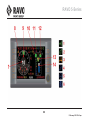
B. 1 Recognizing safety information
This is the safety warning symbol. When you see this symbol in the instruction manual, it is to be considered as a warning against possible bodily injury. Read the
recommended instructions and follow the precautionary measures and the safe working practices.
B. 2 Explanation of the signal words
DANGER!
THE LIFE OF THE USER OR THAT OF OTHER PEOPLE IS DIRECTLY ENDANGERED.
WARNING!
THE OPERATOR OR PERSONS MAY THEMSELVES BE (SERIOUSLY) INJURED OR SERIOUSLY DAMAGE THE PRODUCT. WARNING! INDICATES
DAMAGE TO THE USER/PERSONS OR THE PRODUCT, IF THE USER DOES NOT FOLLOW THE PROCEDURES CAREFULLY.
CAUTION!
THE PRODUCT MAY BE DAMAGED. CAUTION! INDICATES DAMAGE TO THE PRODUCT IF THE USER DOES NOT FOLLOW THE PROCEDURES
CAREFULLY.
NOTE!
NOTE! PROVIDES IMPORTANT INFORMATION ABOUT INSTALLATION, OPERATION OR MAINTENANCE, WHICH IS IMPORTANT BUT DOES NOT
INVOLVE DANGER.
30
5 February 2015 12:49 pm
RAVO 5-Series
B. 3 General safety instructions
Carefully read all the safety instructions in this instruction manual.
B. 3.1 Use the machine specification
The RAVO sweeper has been exclusively designed for sweeping operations on paved/metalled surfaces. Applications and/or use outside of this specification
can affect function/safety.
B. 3.2 Use outside the machine specification
Hazardous situations can occur if the machine is used for purposes other than those for which the RAVO sweeper is intended. The dangers arising out of such
use are the responsibility of the owner/operator or user. The manufacturer cannot be held liable for this.
B. 3.3 User/operator
Make sure the operator/user receives sufficient training/instruction in the use/operation of the sweeper. Do not allow other people to operate the sweeper without
training/instruction. Provide effective instruction on how to correctly operate/use the machine. The operator/user must be notified of the valid traffic regulations
and legislation. Persons under the influence of alcohol, medicines or drugs are not permitted to work with and/or carry out service or repairs on the sweeper.
The user/operator must ensure that while using the sweeper there are no objects or persons in the vicinity of the sweeper, particularly when reversing. Avoid
damage or physical injury. The user/operator is responsible at all times for the safety and well-being of persons in close proximity to the sweeper.
B. 3.4 Maintenance
Keep your sweeper in good working order. Modifications to the sweeper that have not been approved may affect the correct operation and/or safety, warranty
and service life of the sweeper. Maintenance and repair work requires specific knowledge and should therefore be carried out by specialists trained for this
purpose.
If you require additional information to understand any part of this instruction manual, then please contact your RAVO dealer.
31
5 February 2015 12:49 pm
RAVO 5-Series
B. 3.5 Wear suitable clothing and safety equipment
Wear appropriate, close-fitting clothing and personal protective equipment when operating the machine. Be careful with anything that may become caught in the
machine, such as jewellery or long hair. The safe operation of the equipment requires the operator's full attention. Do not wear headphones to listen to the radio
or music whilst operating the machine. Be careful when using a mobile telephone whilst operating the equipment. For work being carried out outside of the driver's
cab, protective measures should be taken, always wear suitable, visible safety clothing, and protection against dust and noise.
B. 3.6 Be careful with fuel and take measures to prevent a fire
Be careful with fuel. It is extremely flammable. Do not smoke or work in the vicinity of naked flames or sparks whilst refuelling the machine. Always switch off the
engine before refuelling the machine. Fill the fuel tanks outside in the open air. Prevent fire by keeping the machine free of dirt, grease and debris. Always clean
up any spilled fuel.
32
5 February 2015 12:49 pm
RAVO 5-Series
B. 3.7 Avoid contact with moving parts
Do not start the machine or the brushes whilst people are standing nearby. Due to their function, many moving parts, such as the side brushes, cannot be
completely shielded. Keep away from these moving parts whilst the machine is in operation. Keep hands, feet and clothing away from the machine's driven parts.
B. 3.8 Avoid contact with hot surfaces
Certain parts inside the engine compartment and the exhaust system of the sweeper can get very hot. Avoid contact with the hot surfaces of these parts in the
sweeper. First allow the sweeper to cool down sufficiently before starting to carry out work on these parts of the sweeper. Avoid physical injury.
B. 3.9 Prevent battery explosions
Battery gas can explode. Keep sparks and flames away from batteries. Never check the charge of a battery by placing a metal object across the terminals. Use
a voltmeter. The battery's earth cable must always be removed first and re-connected last. Do not charge a frozen battery, otherwise it may explode. Always
warm the battery to 16° C (60° F).
33
5 February 2015 12:49 pm
RAVO 5-Series
B. 3.10 Avoid contact with high-pressure liquids
Liquids escaping under high pressure can penetrate the skin and cause serious injury. Avoid this danger by reducing the pressure before disconnecting hydraulic
lines or other lines. Tighten all connections before pressurizing the system. Check for leaks by using a piece of cardboard. Protect your hands and body from
high-pressure liquids. If an accident has occurred, immediately call for medical assistance.
Keep hands and other body parts away from openings and nozzles that spray liquids under high pressure.
B. 3.11 Use the correct equipment and service components
Use tools that are suitable for the task in hand. Inappropriate tools and unsuitable procedures can result in hazardous situations. Only use electrical tools to
tighten and loosen threaded parts. Use tools of the correct size to tighten and loosen parts. Avoid bodily injury that may result from slipping spanners. Only use
service components, which meet the specifications of RAVO bv. These have been tested and approved by RAVO bv. The use of non-original and approved
service components can have a negative impact on the safety and integrity of the sweeper. The use of unapproved service components falls outside the liability
and does not affect the warranty of the machine.
34
5 February 2015 12:49 pm
RAVO 5-Series
B. 3.12 Comply with environmental regulations
Pay attention to the environment and the ecosystem. Before draining any liquid, decide on the best method of disposal. Observe the relevant environmental
regulations when cleaning up oil, fuel, coolant, brake fluid, filters and batteries.
B. 3.13 Carry out maintenance work safely.
Keep the area clean and dry. Remove any accumulated grease, oil or dirt. Never carry out maintenance work or lubricate the machine whilst it is moving. Never
crawl under a rotating sweeper. Provide adequate, safe security when carrying out maintenance work on top of the container. Make sure that all parts are in good
condition and that they are properly installed. Repair damage immediately. Replace worn or broken parts.
B. 3.14 Take a break in good time
Working with the sweeper is labour-intensive, so take adequate rest breaks in good time. Comply with the local regulations and legislation in force relating to the
taking of breaks and operating/driving a vehicle.
B. 3.15 Exhaust gasses
Never allow the engine to operate in an enclosed space. The exhaust gases contain the poisonous carbon monoxide. Inhaling exhaust gases is dangerous to
health and can result in loss of consciousness or death.
35
5 February 2015 12:49 pm
RAVO 5-Series
B. 4 Scrapping the sweeper
If the sweeper is being scrapped, the regulations governing waste processing should be observed, which apply in the location and at the time of scrapping.
When scrapping the sweeper, the following activities must be carried out by a certified and specialist company.
WARNING!
A NUMBER OF SYSTEMS ARE PRESSURISED BY MEANS OF ACCUMULATORS. FIRST DEPRESSURISE THESE SYSTEMS BY DEPRESSURISING THESE
ACCUMULATORS.
WARNING!
PAY ATTENTION THE ENVIRONMENT AND THE ECOSYSTEM. BEFORE DRAINING ANY LIQUID, DECIDE ON THE BEST METHOD OF DISPOSAL. ALWAYS
COMPLY WITH THE RELEVANT ENVIRONMENTAL-PROTECTION MEASURES WHEN CLEARING UP OIL, FUEL, COOLANT, BRAKE FLUID, FILTERS AND
BATTERIES.
B. 4.1 Activities to be completed
•
•
•
•
•
•
•
•
•
•
Remove the batteries
Depressurise the suspension system by discharging the oil pressure into a hydraulic tank
Depressurise the accumulators for the suspension system and remove the accumulators
Depressurise the accumulators for the braking system and remove the accumulators
Remove all fuel from the fuel tank and the system
Remove all hydraulic oil from the hydraulic tank and the system
Remove the ATF oil from the ATF system
Remove all engine oil from the engine block
Remove all coolant from the engine and the cooling system
Remove all the water from the water tanks.
36
5 February 2015 12:49 pm
RAVO 5-Series
37
5 February 2015 12:49 pm
RAVO 5-Series
38
5 February 2015 12:49 pm
RAVO 5-Series
B. 5 Sweeper emergency stop
The RAVO sweeper is fitted with an emergency stop. This emergency stop should only be used in emergency situations in which case all sweeper functions need to
be stopped. After operating this emergency stop, it is only possible to continue to drive the sweeper, all other functions are then put out of operation.
NOTE!
THE EMERGENCY STOP IS ONLY ACTIVATED WHEN THE EMPTY / DRIVE / SWEEP SWITCH (2) IS IN THE SWEEP OR EMPTY POSITION. THE
EMERGENCY STOP IS NOT ACTIVATED IN THE DRIVE POSITION.
WARNING!
AFTER USING THE EMERGENCY STOP, ALWAYS RESOLVE THE HAZARDOUS SITUATION FIRST BEFORE RESETTING THE EMERGENCY STOP.
B. 5.1 Operating the emergency stop
• Depress the emergency stop (1). All sweeping and operating functions of the sweeper are put out of operation.
B. 5.2 Reset the emergency stop
• Turn the emergency stop (1) clockwise. The emergency stop will now be reset
• Set the Empty/Drive/Sweep switch (2) on the dashboard to Drive. All sweeper functions can now be operated again.
39
5 February 2015 12:49 pm
RAVO 5-Series
40
5 February 2015 12:49 pm
RAVO 5-Series
B. 6 Transporting the sweeper
Secure the sweeper to the transport vehicle to the anchor points on the machine using chains or straps with sufficient load capacity.
WARNING!!
SAFELY MANOEUVRE THE SWEEPER ON THE MEANS OF TRANSPORTT AND ALWAYS ENSURE THAT THE TOOLS USED ARE SUITABLE FOR THE
WEIGHT OF THE MACHINE. REFER TO THE SPECIFICATIONS OF THE SWEEPER.
WARNING!
DO NOT MOVE THE SWEEPER WITH A HOIST AS THE SWEEPER IS NOT FITTED WITH LIFTING EYES.
B. 6.1 Securing
• Secure the sweeper at the front at the positions indicated (1).
• Secure the sweeper at the rear at the positions indicated (2).
41
5 February 2015 12:49 pm
RAVO 5-Series
42
5 February 2015 12:49 pm
RAVO 5-Series
C. PRODUCT DESCRIPTION
43
5 February 2015 12:49 pm
RAVO 5-Series
44
5 February 2015 12:49 pm
RAVO 5-Series
C. 1 Vehicle description
The RAVO sweeper combines compact external measurements with a high sweeping and suction capacity.
The following features make the RAVO very user friendly:
•
•
•
•
•
•
•
•
•
•
•
•
•
•
•
•
Easily accessible and user-friendly instruments and operating levers
A cabin that is well insulated against noise and extreme temperatures
Good heating and ventilation options
Good suspension in the driver's seat
Spacious cabin
Good visibility in all directions and a good view of the right-hand brush
Good accessibility of the various vehicle components
A very small turning circle and a short wheelbase
A patented, maintenance-free brush system
Powerful IVECO engine that meets current emission standards
High compacting power for the waste in the container and a high load capacity
A stainless steel container
Low maintenance costs
High resale value
Long service life
Automatic ride-height control
45
5 February 2015 12:49 pm
RAVO 5-Series
46
5 February 2015 12:49 pm
RAVO 5-Series
C. 2 Vehicle operation
The suction nozzle (3) (adjustable in height) sucks in the waste that has been collected by the brushes (2 and 4).The suction fan (8) in the hopper (5) ensures that
there is a lower pressure in the hopper,which causes a flow of air. This flow of air then sucks the waste into the hopper (5) via the suction nozzle (3) and the suction
tube (9).
Water spray nozzles are located in the suction nozzle (3).These water spray nozzles have an important function.The water binds the waste and, as a result, the waste
remains in the hopper (5) better.Very fine waste without water as a binding agent may be blown out of the machine again.Moreover, the water serves as a lubricant
which helps reduce wear and contamination.
Water spray nozzles are also located at the brushes (2 and 4). These water spray nozzles are important to stop clouds of dust being formed when sweeping in dry
conditions.It is, therefore, not necessary to use these sprays during damp weather conditions.
As a result of the construction that has been chosen for the hopper and the suction system, the waste will collect at the back of the hopper (5).In this way, the maximum
capacity of the hopper is used.
The grilles (7) and the suction fan (8) that provides the suction force are located at the top of the hopper.The excess air is expelled by the suction fan (8) at the rear
(6) of the hopper (5).
47
5 February 2015 12:49 pm
RAVO 5-Series
C. 3 Location of the components
48
5 February 2015 12:49 pm
RAVO 5-Series
1: iSystem LED Display Panel
2:Steering column
3:Pedals
4:Heater
5:Dashboard
6:Radio
49
5 February 2015 12:49 pm
RAVO 5-Series
C. 4 Location of the components
50
5 February 2015 12:49 pm
RAVO 5-Series
1:Brush system
2:Container door
3:Service door
4:Container
51
5 February 2015 12:49 pm
RAVO 5-Series
C. 5 Location of the components
52
5 February 2015 12:49 pm
RAVO 5-Series
1:Fuel cap
2:Hydraulic oil filler cap
3:Left-hand safety bracket
4:AdBlue filler cap
53
5 February 2015 12:49 pm
RAVO 5-Series
C. 6 Location of the components
54
5 February 2015 12:49 pm
RAVO 5-Series
1:Water tank fill connection
2:Hand pump
WARNING
NEVER FILL THE WATER TANK WITH SALT WATER OR WATER TO WHICH CHEMICAL INGREDIENTS HAVE BEEN ADDED.THIS MAY CAUSE DAMAGE
TO THE WATER SYSTEM.
WARNING
ALWAYS ENSURE THAT CLEAN AND FRESH WATER IS USED DURING SWEEPING OPERATIONS.UNFRESH, BRACKISH WATER MAY CAUSE DAMAGE
TO HEALTH.PREVENT BACTERIAL INFECTIONS BY REGULARLY RINSING THE WATER SYSTEM THROUGH WITH CLEAN WATER.
55
5 February 2015 12:49 pm
RAVO 5-Series
C. 7 Location of the components
56
5 February 2015 12:49 pm
RAVO 5-Series
1:Inspection hatch suction tube tunnel
2:Suction tube inspection hatch
57
5 February 2015 12:49 pm
RAVO 5-Series
C. 8 Location of the components
58
5 February 2015 12:49 pm
RAVO 5-Series
CAUTION:
DO NOT USE A BATTERY JUMP STARTER TO START THE SWEEPER'S ENGINE.THIS MAY DAMAGE THE SWEEPER'S ELECTRICAL SYSTEM.
CAUTION:
ONLY USE MAINTENANCE-FREE BATTERIES.
1:Battery 2 x 12V
59
5 February 2015 12:49 pm
RAVO 5-Series
C. 9 Location of the components
60
5 February 2015 12:49 pm
RAVO 5-Series
1:High-pressure water pump (optional)
61
5 February 2015 12:49 pm
RAVO 5-Series
C. 10 Location of the components
62
5 February 2015 12:49 pm
RAVO 5-Series
NOTE!
FOR EURO 5 SWEEPERS, IT IS VERY IMPORTANT TO WAIT AT LEAST THREE MINUTES AFTER THE SWEEPER'S ENGINE HAS BEEN STOPPED BEFORE
TURNING OFF THE POSITIVE BATTERY TERMINAL SWITCH.THIS WILL ALLOW THE ADBLUE PUMP TO PUMP THE SYSTEM EMPTY.
1:Positive battery terminal switch
63
5 February 2015 12:49 pm
RAVO 5-Series
C. 11 Location of the components
64
5 February 2015 12:49 pm
RAVO 5-Series
1:Vehicle Identification Number (V.I.N.) plate
2:Vehicle Identification Number (V.I.N.)Chassis
65
5 February 2015 12:49 pm
RAVO 5-Series
66
5 February 2015 12:49 pm
RAVO 5-Series
C. 12 CE declaration of conformity
All machines comply with the associated CE declaration of conformity and CE mark on the machine.
The machine meets the following conditions:
* Machinery Directive (Directive 2006/42/EC).
* EMC Directive (Directive 2004/108/EC).
* Noise emission (Directive 2000/14/EG)
- Measured sound power level of this equipment LWA = XXX dB (A)
- Guaranteed sound power level of this equipment LWA = XXX dB (A)
* At the maximum recommended revolutions per minute of XXXX rpm whilst sweeping.
- Complies with the evaluation procedure: Appendix V.
* The harmonised standards: EN 13019:2001 + A1: 2008 (Machines for road surface cleaning - Safety requirements).
* The international standard ISO9001: 2008, number of the certificate NL008314-1
Bureau Veritas BV, Computerweg 2, 3821 AB Amersfoort, the Netherlands, RvA C 248.
67
5 February 2015 12:49 pm
RAVO 5-Series
68
5 February 2015 12:49 pm
RAVO 5-Series
C. 13 Vehicle Identification Number (VIN)
All machines meet the Machinery Directive 2006/42/EC complete with the associated CE declaration of conformity and CE mark on the machine.You can find the
mark on the right-hand side of the machine by the driver's seat.The Vehicle Identification Number (VIN) is stated on this CE mark.Set out in the table below you can
find an explanation of the structure of the Vehicle Identification Number (VIN).
C. 13.1 Explanation of the Vehicle Identification Number (VIN)
X
L
9
5
F
5
C
6
A
9
0
0
2
0
0
0
1
< Example (VIN)
1
2
3
4
5
6
7
8
9
10
11
12
13
14
15
16
17
< Position (VIN)
WMI
Vehicle description section
Type
X
X
Variant
Vehicle indication section
Subject
Version
X
World manufacturer identification number
X
Type
X
Chassis
X
Engine type
X
Container type
X
Max. speed/Brake system
X
USA control number
X
Model year
X
Serial number (part1)
X
X
X
World manufacturer identification number
(part2)
X
69
5 February 2015 12:49 pm
X
X
Serial number (part2)
RAVO 5-Series
70
5 February 2015 12:49 pm
RAVO 5-Series
D. OPERATING CONTROLS
71
5 February 2015 12:49 pm
RAVO 5-Series
72
5 February 2015 12:49 pm
RAVO 5-Series
D. 1 iSystem LED screen ‘Drive’
The iSystem LED display shows information on the current status of the sweeper.Relevant information is displayed depending on the selected sweeper mode (Dump/
Drive/Sweep).This information can include warnings, status and/or level information, speed and engine information.When the ignition is switched on, all indications
are shown for three seconds.This section describes the driving screen of the iSystem LED display.
D. 1.1 Air filter indicator light (option)
The air filter indicator light (1) goes on when the filter is restricted.
D. 1.2 Fuel filter indicator light
The fuel filter indicator light (2) goes on when the fuel filter is restricted.
WARNING
STOP THE SWEEPER IMMEDIATELY IN A SAFE LOCATION AND SWITCH OFF THE ENGINE.HAVE YOUR SERVICE DEPARTMENT DRAIN THE WATER
FROM THE FUEL SYSTEM.
D. 1.3 Hydraulic oil filter indicator light (option)
The hydraulic oil filter indicator light (3) goes on when the hydraulic return filter is blocked.
D. 1.4 Hydraulic oil level indicator light
The hydraulic oil level indicator light (4) goes on if the oil level in the hydraulic tank is too low.The warning buzzer will also give a signal.
WARNING
IF THE INDICATOR LIGHT IS LIT AFTER YOU START THE ENGINE, OR DURING DRIVING AND/OR DURING NORMAL SWEEPING OPERATIONS,
IMMEDIATELY STOP THE SWEEPER IN A SAFE LOCATION AND IMMEDIATELY SWITCH OFF THE ENGINE.VISUALLY CHECK THE HYDRAULIC OIL
LEVEL ON THE LEVEL/TEMPERATURE GAUGE AND LOOK UNDER THE SWEEPER FOR ANY LEAKS.HAVE THE HYDRAULICS SYSTEM CHECKED BY
YOUR SERVICE DEPARTMENT.
D. 1.5 Drive temperature indicator light
The drive temperature indicator light (5) goes on when the temperature of the drive system becomes too high.The warning buzzer will also give a signal.
WARNING
STOP THE SWEEPER IMMEDIATELY IN A SAFE LOCATION.CHECK THE COOLANT TEMPERATURE OF THE ENGINE AND CHECK THE OIL LEVEL OF
THE HYDRAULICS TANK.HAVE THE DRIVE PUMP CHECKED BY YOUR SERVICE DEPARTMENT.
73
5 February 2015 12:49 pm
RAVO 5-Series
74
5 February 2015 12:49 pm
RAVO 5-Series
D. 1.6 Sweeping limited
The sweeping limited indicator light (6) goes on when the emergency stop is operated, one of the cabin doors is open or there is an internal fault in the PLC.If
the sweeping limited indicator light is on, the sweeping function will be limited or stopped.
D. 1.7 Engine start indicator light
The engine start indicator light (7) goes on when the ignition key is switched on; the engine must not be started yet.Once the engine start indicator light goes out,
the engine may be started.
D. 1.8 Alternator indicator light
The alternator indicator light (8) goes on when the alternator is providing no power or too little to charge the battery.
Stop the sweeper immediately in a safe location and switch off the engine.Tilt the container manually and check the belts of the cooling fan and the alternator
drive.
If the belts are broken, have them replaced.Do not continue to drive with broken belts!
If the belts are still intact, contact your service department.
NOTE
IF THE CHARGING VOLTAGE DROPS BELOW 24 VOLTS THERE IS A DEFECT IN THE CHARGING CIRCUIT.CONTACT YOUR SERVICE DEPARTMENT.
D. 1.9 Coolant indicator light
The coolant temperature indicator light (9) goes on when the temperature of the coolant becomes too hot.
D. 1.10 Fuel indicator light
The fuel indicator light (10) goes on when the fuel level in the fuel tank is less than 15%.
D. 1.11 Engine oil pressure indicator light
The engine oil pressure indicator light (11) goes on when the engine oil pressure is too low.
WARNING
STOP THE SWEEPER IMMEDIATELY IN A SAFE LOCATION AND SWITCH OFF THE ENGINE.HAVE THE LUBRICATION SYSTEM CHECKED BY YOUR
SERVICE DEPARTMENT.
D. 1.12 Dipped beam indicator light
The dipped beam indicator light (12) goes on when the dipped beam switch is activated.
75
5 February 2015 12:49 pm
RAVO 5-Series
76
5 February 2015 12:49 pm
RAVO 5-Series
D. 1.13 Main beam indicator light
The main beam indicator light (13) goes on when the main beam switch is activated.
D. 1.14 Fog light indicator light
The fog light indicator light (14) goes on when the fog light switch is activated.
D. 1.15 Indicator beacon light
The beacon light indicator (15) goes on when the beacon light switch is activated.
D. 1.16 Heated mirror indicator light (option)
The heated mirror indicator light (16) goes on when the heated mirror switch is activated.
D. 1.17 Water in fuel
The water in fuel indicator light (17) indicates that there is water in the fuel filter.
D. 1.18 Brake fluid pressure indicator light
The brake fluid pressure indicator light (18) goes on when the brake fluid pressure is too low.The warning buzzer will also give a signal.
D. 1.19 ABS indicator light
The ABS indicator light (19) goes on when a fault occurs in the ABS system.
D. 1.20 Steering and brake fluid temperature indicator light (Option ABS)
The steering and brake fluid temperature indicator light (20) goes on when the fluid temperature in the tank is too high.The warning buzzer will also give a signal.
D. 1.21 Steering and brake fluid level indicator light
The steering and brake fluid level indicator light (21) goes on when the fluid level in the tank is too low.The warning buzzer will also give a signal.
WARNING
IF THE INDICATOR LIGHT IS LIT AFTER YOU START THE ENGINE, OR DURING DRIVING AND/OR DURING NORMAL SWEEPING OPERATIONS,
IMMEDIATELY STOP THE SWEEPER IN A SAFE LOCATION AND IMMEDIATELY SWITCH OFF THE ENGINE.VISUALLY CHECK THE FLUID LEVEL ON THE
LEVEL/TEMPERATURE GAUGE AND LOOK UNDER THE SWEEPER FOR ANY LEAKS.HAVE THE FLUID SYSTEM CHECKED BY YOUR SERVICE
DEPARTMENT.
D. 1.22 Exhaust cleaning stop (Tier 4)
The exhaust cleaning stop indicator light (22) indicates that the filter regeneration has been blocked by the user.
D. 1.23 Exhaust cleaning (Tier 4)
The exhaust cleaning indicator lamp (23) indicates that the filter regeneration has been initiated by the user.
77
5 February 2015 12:49 pm
RAVO 5-Series
78
5 February 2015 12:49 pm
RAVO 5-Series
D. 1.24 Engine Data Controller (EDC) indicator light
The EDC indicator light (24) goes on when the Engine Data Controller (EDC) malfunctions or performs a check.The indicator light will flash slowly when the
ignition switch is turned on.
D. 1.25 EDC indicator light
The EDC indicator light (25) goes on when there is a serious defect.Stop the vehicle immediately in a safe location and switch off the engine.
D. 1.26 OBD emission values indicator light
The emission values indicator light (26) goes on or flashes when a fault has occurred in the system or the level of AdBlue in the tank is too low.
WARNING
IF THE OBD INDICATOR LIGHT GOES ON OR FLASHES, STOP THE MACHINE IN A SAFE LOCATION AND TURN OFF THE ENGINE.CHECK THE ADBLUE
LEVEL IN THE TANK.IF THE TANK IS FULL, HAVE THE SYSTEM CHECKED BY THE SERVICE DEPARTMENT.
WARNING
DRIVING WITH A LOW ADBLUE LEVEL WILL HARM THE ENVIRONMENT.THE SYSTEM WILL THEN NO LONGER MEET THE EURO5 STANDARD.THE
ENGINE'S POWER WILL BE REDUCED BY THE SYSTEM.FAILURE TO COMPLY WITH THE EURO 5 STANDARD IS A VIOLATION OF THE LAW.
D. 1.27 On-board computer indicator light
The on-board computer indicator light (27) goes on if the on-board computer detects an internal fault.
D. 1.28 Parking brake indicator light (handbrake)
The parking brake indicator light (28) goes on when the parking brake is engaged.
D. 1.29 Engine stop indicator light
The engine stop indicator light (29) goes on if the engine stops of its own accord.The indicator light flashes when the engine is going to be stopped.
D. 1.30 MSC indicator light
The Machine Safety Controller (MSC) indicator light (30) goes on when the (machine control) MSC signals a fault.
D. 1.31 Container rear door indicator light (only CD version)
The container rear door indicator light (31) goes on when the rear door of the container is not sealed properly.
D. 1.32 Container pusher indicator light (only CD version)
The container pusher indicator light (32) goes on when the pusher of the container dump is not stowed away properly.
79
5 February 2015 12:49 pm
RAVO 5-Series
80
5 February 2015 12:49 pm
RAVO 5-Series
D. 1.33 Container service doors indicator light (only CD version)
The container service doors indicator light (33) goes on when one of the container service doors is not properly closed.
D. 1.34 Container raised indicator light
The container raised indicator light (34) goes on when the container is tilted (ST version) or raised (CD version).
D. 1.35 Engine coolant level indicator light (only Tier 4)
The engine coolant level indicator light (35) goes on when the engine coolant level is too low.
D. 1.36 Direction indicators
When the direction indicator lever on the steering column is operated, the indicator light (36) for the direction indicators will flash.The warning buzzer will also
give a pulsing signal
D. 1.37 Exhaust temperature indicator light (Euro 6 and Tier 4)
The exhaust temperature indicator light (37) goes on when the exhaust temperature is high.
D. 1.38 Direction indicator
The driving direction indicator (38) indicates the selected mode of the driving direction switch.The direction indicator shows three positions: forward/neutral/
reverse.
D. 1.39 Rotation/selection knob
The rotation/selection knob (39) of the iSystem LED screen is used to scroll or confirm selections by turning the knob.This is only possible if the screen mode
allows it.
D. 1.40 Spraywater level gauge
The spraywater level gauge (40) shows the amount of water in the spraywater tank.
D. 1.41 Clock
The clock displays the current time.This can be set manually
D. 1.42 AdBlue level gauge
The AdBlue level gauge (42) shows the amount of AdBlue in the AdBlue tank.The gauge also includes an LED that goes on when the level in the AdBlue tank
falls below 15%.Always make sure that the AdBlue tank is sufficiently filled.
WARNING
DRIVING WITH A LOW ADBLUE LEVEL WILL HARM THE ENVIRONMENT.THE SYSTEM WILL THEN NO LONGER MEET THE EURO5 STANDARD.THE
ENGINE'S POWER WILL BE REDUCED BY THE SYSTEM.FAILURE TO COMPLY WITH THE EURO 5 STANDARD IS A VIOLATION OF THE LAW.
81
5 February 2015 12:49 pm
RAVO 5-Series
82
5 February 2015 12:49 pm
RAVO 5-Series
D. 1.43 Fuel level gauge
The fuel level gauge (43) indicates the quantity of fuel in the fuel tank.Always make sure that the fuel tank is sufficiently filled.The gauge also includes an LED
that goes on when the level in the fuel tank falls below 15%.The indicator lamp (10) goes on.
D. 1.44 Selection knob
The selection knob (44) of the iSystem LED screen is used to confirm selections.This is only possible if the screen mode allows it.In total there are 9 buttons.Other
screens can be activated with these buttons.
D. 1.45 Speedometer
The speedometer (45) shows the current driving speed of the sweeper.Digital and analogue.
D. 1.46 Rev. counter
The rev. counter (46) indicates the engine revs.Digital and analogue.
83
5 February 2015 12:49 pm
RAVO 5-Series
84
5 February 2015 12:49 pm
RAVO 5-Series
D. 2 iSystem LED display – sweeping
The iSystem LED display shows information on the current status of the sweeper.Relevant information is displayed depending on the selected sweeper mode (Dump/
Drive/Sweep).This information can include warnings, status and/or level information, speed and engine information.This section only describes the relevant
information about the ‘Sweep’ LED screen.The items previously discussed in connection with the ‘Drive’ screen are not described here.
D. 2.1 Silent indicator light (option)
The silent indicator light (1) is lit when this option is activated.
D. 2.2 Fan indicator light
The fan indicator light (2) is lit when this fan is activated.
D. 2.3 Suction nozzle indicator light
The suction nozzle indicator light (3) is lit when the nozzle is activated.
D. 2.4 Spraywater pump indicator light
The spraywater pump indicator light (4) is lit when the spraywater pump is activated.
D. 2.5 Water recirculation indicator light (option)
The water recirculation indicator light (1) is lit when this option is activated.
D. 2.6 HP water pump (option)
The HP water pump indicator light (6) is lit when this option is activated.
D. 2.7 Speedometer
The speedometer (7) shows the current driving speed of the sweeper.Digital only.
D. 2.8 Rev. counter
The rev. counter (8) indicates the engine revs.Analogue only.
D. 2.9 Ideal sweep rev range
The tachometer is labelled with the rev range (9) for optimum sweeping.Under normal conditions.
D. 2.10 Lighting
The lighting indicator (10) indicates whether the work lighting is on.Green = on.
D. 2.11 Brush washers
The brush sprayer indicator (11) indicates whether the brush sprayers are activated.Blue = on.
D. 2.12 Brush speed
The brush speed indicator (12) indicates the minimum and maximum brush speed.
85
5 February 2015 12:49 pm
RAVO 5-Series
86
5 February 2015 12:49 pm
RAVO 5-Series
D. 2.13 Suction nozzle and suction tube sprayers
The suction nozzle and suction tube sprayer indicator (13) indicates whether the sprayers in the suction nozzle and suction tube are activated.Blue = on.
D. 2.14 Water level gauge
The water level gauge (14) indicates the water level percentage of the water tanks.
87
5 February 2015 12:49 pm
RAVO 5-Series
88
5 February 2015 12:49 pm
RAVO 5-Series
D. 3 iSystem LED display ‘Dump’
The iSystem LED display shows information on the current status of the sweeper.Relevant information is displayed depending on the selected sweeper mode (Dump/
Drive/Sweep).This information can include warnings, status and/or level information, speed and engine information.This section only describes the relevant
information about the ‘Dump’ LED screen.The items previously discussed in connection with the ‘Drive’ and ‘Sweep’ screens are not described here.
D. 3.1 Dump status indicator
The Dump status indicator shows which position the container is in during Dumping.
D. 3.2 Rev. counter
The rev. counter (2) indicates the engine revs.Analogue only.
D. 3.3 Speedometer
The speedometer (3) shows the current driving speed of the sweeper.Digital only.
D. 3.4 HP water pump (option)
The HP water pump indicator light (4) is lit when this option is activated.
89
5 February 2015 12:49 pm
RAVO 5-Series
90
5 February 2015 12:49 pm
RAVO 5-Series
D. 4 Dashboard
The dashboard is situated to the left of the steering wheel on top of the central console.On the dashboard you will find all the major switches for the brushing, suction
and spray unit and the hand accelerator activation button.
NOTE
THE LAYOUT OF THE DASHBOARD CAN DIFFER DEPENDING ON THE MACHINE, TO ACCOMMODATE ANY SPECIAL OPTIONS ADDED.THE LAYOUT
DESCRIBED HERE IS THE STANDARD LAYOUT WITH THE MOST COMMON OPTIONS.THE FUNCTIONALITY OF THE SWITCHES REMAINS THE SAME
EVEN IF THEY ARE FITTED IN A DIFFERENT PLACE.
D. 4.1 Hand accelerator activation button
The operating speed of the engine can be set with the hand accelerator activation button (1) if the Dump/Drive/Sweep switch is in the Dump or Sweep position.
D. 4.2 Brush switch (with ‘independently lifting of right brush’ option)
The brush switch (2) has three positions:
D. 4.2.1 Position ‘0’/brush-drive off
The brush drive and spraywater provision are switched off.
D. 4.2.2 Position ‘1’/brush-drive on
The engine must be running, the Dump/Drive/Sweep switch (14) must be set to Sweep and the joystick for the brushes must be moved to the ‘brush down’
position.
The brushes move down and start turning.
D. 4.2.3 Position ‘2’/brush drive on and spraywater on
Switch the spraywater pump switch (3) on
The spraywater provision on the brushes and/or in the suction nozzle will start to spray (depending on the position of the spraywater pump switch).
91
5 February 2015 12:49 pm
RAVO 5-Series
92
5 February 2015 12:49 pm
RAVO 5-Series
(with ‘independent lifting of right brush’ option)
D. 4.2.4 Position ‘0’/brush-drive off
The brush drive and spraywater provision are switched off.
D. 4.2.5 Position ‘1’/brush-drive on
The engine must be running, the Dump/Drive/Sweep switch (14) must be set to Sweep and the joystick for the brushes must be moved to the ‘brush down’
position
The right brush moves down and starts turning.
D. 4.2.6 Position ‘2’/brush drive on and spraywater on
Switch the spraywater pump switch (3) on
The spraywater provision on the right brush and/or in the suction nozzle will start to spray (depending on the position of the spraywater pump switch).
D. 4.3 Spraywater pump switch
The spraywater pump switch (3) has three positions:
D. 4.3.1 Position ‘0’/spraywater pump off
The spraywater pump is off
D. 4.3.2 Position ‘1’/spraywater pump on
The engine must be running and the Dump/Drive/Sweep (14) switch must be set to Sweep
The spraywater provision to the brushes is activated.
D. 4.3.3 Position ‘2’/sprayers in suction nozzle
In addition to the spraywater provision to the brushes, the spraywater provision in the suction nozzle is now also switched on.
D. 4.4 Fan switch
The fan switch (4) switches on the suction fan provided the Dump/Drive/Sweep switch (14) is set to Sweep.
D. 4.5 Suction nozzle switch, raise/lower
With the raise/lower suction nozzle switch (5) the suction nozzle can be adjusted up or down independently of the brushes,e.g. to suck up large quantities of
leaves.In that case a bigger suction nozzle opening will be required.
93
5 February 2015 12:49 pm
RAVO 5-Series
94
5 February 2015 12:49 pm
RAVO 5-Series
D. 4.6 Brush switch (with ‘independently lifting of left brush’ option)
The brush switch (6) has three positions: option
D. 4.6.1 Position ‘0’/brush-drive off
The brush drive and spraywater provision are switched off.
D. 4.6.2 Position ‘1’/brush-drive on
The engine must be running and the Dump/Drive/Sweep switch (14) must be in the Sweep position
The left brush starts to rotate and is lowered.
D. 4.6.3 Position ‘2’/brush drive on and spraywater on
Switch the spraywater pump switch (3) on
The spraywater provision on the left brush and/or in the suction nozzle will start to spray (depending on the position of the spraywater pump switch).
D. 4.7 Brush speed regulator
This regulator (7) provides infinite adjustment of the rotational speed of the brushes.
WARNING
YOU MUST NOT ALLOW ANY PERSONS WITHIN THE RANGE OF THE THIRD BRUSH WHEN THIS THIRD BRUSH IS IN USE.
D. 4.8 Third brush speed regulator (option)
With this regulator (8) the rotation speed of the third brush can be continuously regulated from zero rpm/min to max.
D. 4.9 Third brush double angle adjustment switch (option)
The angle (left/right) of the third brush can be adjusted with this regulator (9).
D. 4.10 Third brush angle adjustment regulator (option)
The angle (forward/backward) of the third brush can be adjusted with this regulator (10).
D. 4.11 Third brush spraywater switch (option)
This switch (11) releases the spraywater supply to the third brush.But before you do this you must switch on the water pump (3) and the brush drive on the door
console (see Door Console Chapter).
95
5 February 2015 12:49 pm
RAVO 5-Series
96
5 February 2015 12:49 pm
RAVO 5-Series
D. 4.12 Ride-height control switch, front axle
With the ride-height control switch (12) for the front axle it is possible to temporarily bypass the automatic ride-height control.For instance if there is insufficient
ground clearance or when a speed ramp or pavement has to be mounted.
Application of the ride-height control:
• Press the ride-height control switch for approx. 5 seconds
• The sweeper will lift
• The light in the switch lights up
• The sweeper remains elevated for approx. 25 seconds
• The light in the switch will switch off
• The sweeper will drop down.
NOTE
IN THIS ELEVATED POSITION YOU MUST NOT DRIVE FOR LONGER PERIODS AND/OR WITH A SPEED OF MORE THAN 4 KM/H.
DRIVING IN AN ELEVATED POSITION CAUSES MORE WEAR AND TEAR ON THE TYRES.
IF IT IS NECESSARY TO DRIVE FOR MORE THAN 15 SECONDS IN THE ELEVATED POSITION, YOU MUST PRESS THE RIDE-HEIGHT CONTROL SWITCH
AGAIN AFTER THE LIGHT HAS SWITCHED ITSELF OFF.THE SWEEPER WILL THEN AGAIN LIFT FOR 15 SECONDS.
IF IT IS NECESSARY TO DRIVE FOR LESS THAN 15 SECONDS IN THE ELEVATED POSITION, YOU MUST PRESS THE RIDE-HEIGHT CONTROL SWITCH
AGAIN WITHIN THE 15 SECONDS.THE SWEEPER WILL THEN DROP DOWN AGAIN TO ITS NORMAL DRIVE-HEIGHT.
D. 4.13 Third brush motor rotation direction switch
This switch (13) adjusts the rotation direction of the third brush.
This switch has three positions:
D. 4.13.1 Position ‘0’/centre position
In this position the brush is at a standstill and the water supply is shut off
D. 4.13.2 Position ‘1’/up position
In this position the third brush rotates clockwise and the water supply is released, provided the spraywater switch (11) is switched on and the joystick for the
third brush has been moved to the ‘brush down’ position
D. 4.13.3 Position ‘2’/down position
In this position the third brush rotates anti-clockwise and the water supply is released, provided the spraywater switch (11) is switched on and the joystick
for the third brush has been move to the ‘brush down’ position.
97
5 February 2015 12:49 pm
RAVO 5-Series
98
5 February 2015 12:49 pm
RAVO 5-Series
D. 4.14 Dump/Drive/Sweep switch
The Dump/Drive/Sweep switch (14) makes it possible to choose between sweeping, driving or Dumping the container.
D. 4.14.1 Dump
In the Dump position the remote control for Dumping the container is switched on.
D. 4.14.2 Drive
In the Drive position the sweeping function is switched off and the brushes and suction nozzle are stowed away under the sweeper.
D. 4.14.3 Sweeping
In the Sweep position the sweeping function is switched on.Switches 7, 5, 2, 3, 6, 16 and 17 pre-select the settings with which sweeping is to be carried
out.If the Dump/Drive/Sweep button is put in neutral, the sweeping function will be switched off and the brushes and suction nozzle will be stowed away
under the sweeper.
D. 4.15 12V connection
This socket is intended for connection of 12-volt devices with a maximum draw of10A.
D. 4.16 Suction nozzle lighting switch/3rd brush lighting (option)
With the suction nozzle lighting switch (16) it is possible to switch on the suction nozzle lighting.This is only possible if the Dump/Drive/Sweep switch (14) is set
to Sweep.It is also possible with this switch to switch on the third brush lighting (if present).
D. 4.17 Brush lighting, right/left
With this switch (17) it is possible to switch on the lighting on the left or right brush.This is only possible if the Dump/Drive/Sweep switch (14) is set to Sweep.
D. 4.18 High pressure water pump switch (option)/Swasher (option)
This switch (18) switches on the high-pressure water pump.This is only possible if the Dump/Drive/Sweep switch (14) is set to Dump.This switch (18) switches
on the swasher system.This is only possible if the Dump/Drive/Sweep switch (14) is set to Sweep.
D. 4.19 Operating light(s) (option)
This switch (19) activates the worklamps on the machine.
D. 4.19.1 Front
Moving this switch to the front position activates the worklamps at the front of the machine.Press the switch in this direction again to switch off the worklamps.
D. 4.19.2 Rear
Moving this switch to the rear position activates the worklamps at the rear of the machine.Press the switch in this direction again to switch off the worklamps.
99
5 February 2015 12:49 pm
RAVO 5-Series
100
5 February 2015 12:49 pm
RAVO 5-Series
D. 4.20 Water recirculation system (option)
The water recirculation system can be activated using this switch (20).
D. 4.21 Brush angle adjustment left (option)
This switch (21) activates the left-side brush angle adjustment.
D. 4.22 Suction nozzle camera (option)
The suction nozzle camera (22) has two positions: standard
D. 4.22.1 Position ‘0’/suction nozzle camera off
The suction nozzle camera and spraywater provision are switched off.
D. 4.22.2 Position ‘1’/suction nozzle camera on
The suction nozzle camera is switched on.
D. 4.22.3 Position ‘1+’/suction nozzle camera spraywater on
Keep the button pressed and the spraywater provision is activated.
The spraywater provision on the suction nozzle will start to spray (depending on the position of the spraywater pump switch).
101
5 February 2015 12:49 pm
RAVO 5-Series
102
5 February 2015 12:49 pm
RAVO 5-Series
D. 5 iSystem
The RAVO sweeper is equipped with the RAVO iSystem.This iSystem displays information about the mode and status of the sweeper and its systems.The iSystem
contains 3 levels.The general Dump/Drive/Sweep level, the driver's information level and the dealer level.Only the general Dump/Drive/Sweep level and driver's
information level are described here.
The general Dump/Drive/Sweep level is the level that is displayed on the iSystem LED display by default when starting the sweeper, depending on the selected mode
(Dump/Drive/Sweep).
WARNING
ONLY START THE DRIVER'S INFORMATION LEVEL IF THE MACHINE IS PARKED IN A SAFE PLACE.
The driver's information level can be activated by simultaneously pressing selection buttons S2 and S7 on the iSystem LED display.This will start the main menu of
the driver's information level.The screens of the driver's of information level will be described separately.
D. 5.1 Function keys
Certain screens of the iSystem can be accessed through the function keys.These keys are located on the iSystem LED display.The functions of the function keys
will be described one at a time.
D. 5.2 Information screens
Certain screens of the iSystem have additional associated information screens that can be activated using the information function key, S1.The function of this
function key depends on the selected screen.
103
5 February 2015 12:49 pm
RAVO 5-Series
104
5 February 2015 12:49 pm
RAVO 5-Series
D. 5.3 Start-up screen (1)
The start-up screen (1) will be visible during starting of the sweeper.Once the iSystem is ready, this screen will be replaced by one of the standard screens (Dump/
Drive/Sweep).This may take a few seconds.
NOTE
WHEN THE SWEEPER IS SWITCHED OFF, THE ISYSTEM LED DISPLAY WILL REMAIN ACTIVE FOR FIVE MINUTES.THE DISPLAY WILL SWITCH OFF
AUTOMATICALLY AFTER FIVE MINUTES.
105
5 February 2015 12:49 pm
RAVO 5-Series
106
5 February 2015 12:49 pm
RAVO 5-Series
D. 5.4 Driving screen (2)
The Driving screen (2) will be displayed first after starting the sweeper.This displays all the important sweeper system information during driving.
D. 5.5 Sweeping screen (3)
When the Sweeping mode is selected the Sweeping (3) screen will be shown.This displays all the important sweeper system information during sweeping.
D. 5.6 Dumping screen (4)
When the Dumping mode is selected the Dumping (4) screen will be shown.This displays all the important sweeper system information during Dumping of the
container.
NOTE
THE DUMP/DRIVE/SWEEP SCREENS HAVE AN INFO-SCREEN THAT CAN BE ACTIVATED WITH FUNCTION KEY S1.
107
5 February 2015 12:49 pm
RAVO 5-Series
108
5 February 2015 12:49 pm
RAVO 5-Series
D. 5.7 Main menu screen (5)
Pressing keys S2 and S7 simultaneously takes you to the main menu of the driver's information level.The various choices in this menu can be selected and
activated with the rotation/selection knob (5b).By turning the knob (5b) you can scroll through the menu items; by pressing the button (5b) the selected option
can be activated.
D. 5.7.1 Exit key (5a)
Pressing the exit button (5a) exits the main menu screen and returns to the Dump/Drive/Sweep screens.
D. 5.7.2 Rotation/selection knob (5b)
The various choices in this menu can be selected and activated with the rotation/selection knob (5b).
D. 5.7.3 Dealer level (5c)
This choice leads to the dealer login screen.This is not intended for the driver and will not be discussed further.
D. 5.7.4 Switch control (5d)
This choice leads to the switch control menu.Here, additional selections are made to test all control switches.
D. 5.7.5 Driver's information (5e)
This choice leads to the driver's information screen.This is where the machine configuration and iSystem information are found.
D. 5.7.6 Machine diagnostics (5f)
This choice leads to the driver's diagnostic screen.This is where system information and fault codes are shown.
D. 5.7.7 Telemetry (5g)
This choice leads to the driver's telemetry screens.Technical data for the engine and systems are shown here on several screens.
D. 5.7.8 iSystem LED display configuration screen (5h)
This choice leads to the driver's iSystem configuration screen.This is where the clock and the brightness of the screen can be set.
109
5 February 2015 12:49 pm
RAVO 5-Series
110
5 February 2015 12:49 pm
RAVO 5-Series
D. 5.8 iSystem telemetry screens (6)
Selection (6) from the main menu leads to the telemetry screens.
D. 5.8.1 Telemetry screen 1 of 4 (6a)
Telemetry screen (6a) displays engine data.
D. 5.8.2 Telemetry screen 2 of 4 (6b)
Telemetry screen (6b) displays drive system data.
D. 5.8.3 Telemetry screen 3 of 4 (6c)
Telemetry screen (6c) displays drive system data.
D. 5.8.4 Telemetry screen 4 of 4 (6d)
Telemetry screen (6d) displays brush system data.
111
5 February 2015 12:49 pm
RAVO 5-Series
112
5 February 2015 12:49 pm
RAVO 5-Series
D. 5.9 Telemetry screen (6a)
The following engine data can be read on telemetry screen (6a).
•
•
•
•
•
•
1 Engine coolant temperature
2 Battery voltage
3 Engine oil temperature
4 Engine oil pressure
5 Fuel temperature
6 Turbo pressure
113
5 February 2015 12:49 pm
RAVO 5-Series
114
5 February 2015 12:49 pm
RAVO 5-Series
D. 5.10 Telemetry screen (6b)
The following drive system data can be read on telemetry screen (6b).
•
•
•
•
7 Flow drive pump valve forward
8 Flow drive pump valve reverse
9 Flow drive pump valve left
10 Flow drive pump valve right
115
5 February 2015 12:49 pm
RAVO 5-Series
116
5 February 2015 12:49 pm
RAVO 5-Series
D. 5.11 Telemetry screen (6c)
The following drive system data can be read on telemetry screen (6c).
•
•
•
•
•
11 Drive system pressure sensor A
12 Drive system pressure sensor B
13 Drive system oil temperature
14 Parking brake fluid pressure
15 Oil pressure suspension/brake system
117
5 February 2015 12:49 pm
RAVO 5-Series
118
5 February 2015 12:49 pm
RAVO 5-Series
D. 5.12 Telemetry screen (6d)
The following brush system data can be read on telemetry screen (6d).
•
•
•
•
16 Oil pressure, main valve, brush system
17 Oil pressure, valve block, third brush
18 Rotational speed, brushes
19 Rotational speed, third brush
119
5 February 2015 12:49 pm
RAVO 5-Series
120
5 February 2015 12:49 pm
RAVO 5-Series
D. 5.13 Display settings menu (7)
Selection (7) from the main menu leads to the display settings menu.Here you can adjust the clock and screen settings.
D. 5.13.1 Screen brightness (7a)
The brightness of the display can be set manually on the screen (7a) or automatically by the light sensor.
D. 5.13.2 setting the clock (7b)
On screen (7b) the clock can be set and the changes can be saved.
121
5 February 2015 12:49 pm
RAVO 5-Series
122
5 February 2015 12:49 pm
RAVO 5-Series
D. 5.14 Dealer login menu (8)
Selection (8) from the main menu leads to the dealer login menu.
123
5 February 2015 12:49 pm
RAVO 5-Series
124
5 February 2015 12:49 pm
RAVO 5-Series
D. 5.15 iSystem check menu (9)
Selection (9) from the main menu leads to the iSystem check menu.Here you can check the system functions and components.
D. 5.15.1 Check screen pedal/switches and lights (9a)
On screen (9a) you can select the pedal/switches and lights check screen.
D. 5.15.2 Check screen brake and ride-height control (9b)
On screen (9b) you can select the brake and ride-height control check screen.
D. 5.15.3 Check screen main valve block brush system (9c)
On screen (9c) you can select the main valve block check screen.
D. 5.15.4 Check screen non-hydraulic options (9d)
On screen (9d) you can select the non-hydraulic options check screen.
D. 5.15.5 Check screen hydraulic options (9e)
On screen (9e) you can select the hydraulic option check screen.
D. 5.15.6 Check screen valve block third brush (9f)
On screen (9f) you can select the valve block third brush check screen.
D. 5.15.7 Check screen container valve block (9g)
On screen (9g) you can select the container valve block check screen.
D. 5.15.8 Button check menu (9h)
On screen (9h) you can select the button check menu.
125
5 February 2015 12:49 pm
RAVO 5-Series
126
5 February 2015 12:49 pm
RAVO 5-Series
D. 5.16 Check screen pedal/switches and lights (9a)
The pedal/switch and lighting check screen shows the functions of the accelerator, brake and reverse pedals, the door switches and the lighting.
•
•
•
•
•
•
•
1 Brake pedal
2 Accelerator pedal
3 Door switches (one indicator for both switches)
4 Work lighting
5 Reverse pedal channel 1 and channel 2
6 Emergency stops (dashboard and container remote control)
7 Driving direction switch position
127
5 February 2015 12:49 pm
RAVO 5-Series
128
5 February 2015 12:49 pm
RAVO 5-Series
D. 5.17 Check screen brake and ride-height control (9b)
The brake and ride-height check screen shows the function parameters of the brake and ride-height control valves.Green = OKAmber = Open circuit Red = Short
circuit
D. 5.17.1 Explanation of valves
• H4 = Front wheel suspension up (manually)
• H5 = Front wheel suspension down left (automatic)
• H6 = Front wheel suspension down right (automatic)
NOTE
THE BRAKE AND RIDE-HEIGHT CONTROL SCREEN HAS AN INFO-SCREEN THAT CAN BE ACTIVATED WITH FUNCTION KEY S1.
129
5 February 2015 12:49 pm
RAVO 5-Series
130
5 February 2015 12:49 pm
RAVO 5-Series
D. 5.18 Check screen main valve block brush system (9c)
The main valve block brush system check screen shows the function parameters of the main valves for the brushes.Green = OKAmber = Open circuit Red =
Short circuit
D. 5.18.1 Explanation of valves
•
•
•
•
•
•
•
•
•
•
•
•
•
•
•
•
•
•
•
H12 = Lower container
H13 = Tilt container
H14 = Brushes up
H15 = Brushes down
H16 = Suction nozzle down
H17 = Suction nozzle up
H18 = Brush unit to right
H19 = Brush unit to left
H20 = Suction nozzle flap open
H21 = Suction-nozzle valve close
H22 = Brush speed
H23 = Main-pressure valve
H25 = High-pressure water pump (option)
H26 = Separate brushes, up, left (option)
H27 = Separate brushes, down, left (option)
H48 = Gutter brush, horizontal, left (option)
H49 = Gutter brush, vertical, left (option)
H50 = Gutter brush, horizontal, right (option)
H51 = Gutter brush, vertical, right (option)
NOTE
THE MAIN VALVE BLOCK BRUSH SYSTEM SCREEN HAS AN INFO-SCREEN THAT CAN BE ACTIVATED WITH FUNCTION KEY S1.
131
5 February 2015 12:49 pm
RAVO 5-Series
132
5 February 2015 12:49 pm
RAVO 5-Series
D. 5.19 Check screen non-hydraulic options (9d)
The non-hydraulic options check screen (9d) shows the function parameters of the water valves, spraywater pump clutch and water recirculation valve.Green =
OKAmber = Open circuit Red = Short circuit
D. 5.19.1 Explanation of valves
•
•
•
•
•
•
•
W1 = Water valve, brushes
W2 = Water valve, suction nozzle and suction tube
W3 = Water valve, third brush (option)
W4 = Water valve, left sweeping (option)
W5 = Water valve, 50% reduction (option)
WPC = Spraywater pump clutch
WRC = Water recirculation valve
NOTE
THE NON-HYDRAULIC OPTIONS SCREEN HAS AN INFO-SCREEN THAT CAN BE ACTIVATED WITH FUNCTION KEY S1.
133
5 February 2015 12:49 pm
RAVO 5-Series
134
5 February 2015 12:49 pm
RAVO 5-Series
D. 5.20 Check screen hydraulic options (9e)
The hydraulic options screen (9e) shows the function parameters of the hydraulic options silent and independent brush lifting.Green = OKAmber = Open circuit
Red = Short circuit
D. 5.20.1 Explanation of valves
• H28 = Independent brush lifting left
• H29 = Independent brush lifting right
• H55 = Noise reduction (silent)
NOTE
THE HYDRAULIC OPTIONS SCREEN HAS AN INFO-SCREEN THAT CAN BE ACTIVATED WITH FUNCTION KEY S1.
135
5 February 2015 12:49 pm
RAVO 5-Series
136
5 February 2015 12:49 pm
RAVO 5-Series
D. 5.21 Check screen valve block third brush (9f)
The valve block third brush system check screen (9f) shows the function parameters of the third brush valves.Green = OKAmber = Open circuit Red = Short circuit
D. 5.21.1 Explanation of valves
•
•
•
•
•
•
•
•
•
•
•
•
•
•
H31 = Shut-off valve
H32 = Raise brush
H33 = Pressure-control valve
H34 = Slide to left
H35 = Slide to right
H36 = Swivel to left
H37 = Swivel to right
H38 = Brush rotation, clockwise
H39 = Brush rotation, anti-clockwise
H40 = Main valve, third brush
H41 = Brush angle up
H42 = Brush angle down
H43 = Brush angle up sideways (option)
H44 = Brush angle down sideways (option)
NOTE
THE VALVE BLOCK THIRD BRUSH SYSTEM SCREEN HAS AN INFO-SCREEN THAT CAN BE ACTIVATED WITH FUNCTION KEY S1.
137
5 February 2015 12:49 pm
RAVO 5-Series
138
5 February 2015 12:49 pm
RAVO 5-Series
D. 5.22 Check screen valve block container (9g)
The valve block container check screen (9g) shows the function parameters of the container valves.Green = OKAmber = Open circuit Red = Short circuit
D. 5.22.1 Explanation of valves
•
•
•
•
H10 = Container door open
H11 = Container door closed
H52 = Container pusher extended (CD version)
H53 = Container pusher retracted (CD version)
NOTE
THE VALVE BLOCK CONTAINER SCREEN HAS AN INFO-SCREEN THAT CAN BE ACTIVATED WITH FUNCTION KEY S1.
139
5 February 2015 12:49 pm
RAVO 5-Series
140
5 February 2015 12:49 pm
RAVO 5-Series
D. 5.23 Button check menu (9h)
Selection (9h) in the iSystem check menu is used to select the functions of all the controls and switches.This allows you to check system functions.
D. 5.23.1 Check screen armrest (9ha)
On screen (9ha) you can select the armrest switch check screen.
D. 5.23.2 Check screen dashboard (9hb)
On screen (7hb) you can select the dashboard check screen.
D. 5.23.3 Check screen remote control container (9hc)
On screen (7hc) you can select the remote control check screen.
141
5 February 2015 12:49 pm
RAVO 5-Series
142
5 February 2015 12:49 pm
RAVO 5-Series
D. 5.24 Button check screen armrest (9ha)
The armrest button check screen (9ha) displays the function parameters of the switches and joysticks.Green = OK
D. 5.25 Button check dashboard (9hb)
The dashboard button check screen (9hb) displays the function parameters of the dashboard switches.Green = OK
D. 5.26 Button check remote control container (9hc)
The remote control container check screen (9hc) displays the function parameters of the control buttons.Green = OK
143
5 February 2015 12:49 pm
RAVO 5-Series
144
5 February 2015 12:49 pm
RAVO 5-Series
D. 5.27 Driver's information screen (10)
Selection (10) from the main menu leads to the driver's information screen.This screen provides relevant general information.
D. 5.27.1 Vehicle Identification Number (VIN) (10a)
The machine's VIN is shown here.
D. 5.27.2 Engine, sweeping hours meter and total distance travelled (10b)
The sweeper's current engine hours and sweeping hours are shown here.
D. 5.27.3 Option string (10c)
The option code is displayed here. You can use this code to determine which options are active on the sweeper.
D. 5.27.4 Software version PLC and display (10d)
Information about the current software version for the PLC and the iSystem display are shown here.
D. 5.27.5 Firmware version PLC and display (10e)
Information about the current firmware version for the PLC and the iSystem display are shown here.
D. 5.27.6 Service interval meter (10f)
The remaining time before the next service interval is shown here.
145
5 February 2015 12:49 pm
RAVO 5-Series
146
5 February 2015 12:49 pm
RAVO 5-Series
D. 5.28 Button check menu (11)
Selection (11) from the main menu leads to the driver's diagnostics screen.This screen displays relevant information about the systems.
D. 5.28.1 Vehicle Identification Number (VIN) (11a)
The machine's VIN is shown here.
D. 5.28.2 Engine, sweeping hours meter and total distance travelled (11b)
The sweeper's current engine hours and sweeping hours are shown here.
D. 5.28.3 Status CAN systems (11c)
The status of the CAN systems are presented as colour codes here.
• Grey = Inactive
• Green = OK
• Yellow = Timeout
• Orange = Fault detected
• Red = Bus fault
D. 5.28.4 Status PLC (11d)
The status of the PLC is presented as colour codes here.
• Grey = Inactive
• Green = OK
• Yellow = Timeout
• Orange = Fault detected
• Red = Bus fault
D. 5.28.5 Fault codes on-board computer (11e)
The last 8 fault codes from the on-board computer are shown here.
D. 5.28.6 Fault codes EDC and DCU (11f)
The last 8 fault codes from the EDC (Electronic Diesel Controller) and the DCU (Dosing Control Unit) as shown here.
D. 5.28.7 Fault codes ABS (11g)
The last 8 fault codes from the ABS are shown here.
D. 5.28.8 Service interval meter (11h)
The remaining time before the next service interval is shown here.
147
5 February 2015 12:49 pm
RAVO 5-Series
148
5 February 2015 12:49 pm
RAVO 5-Series
D. 6 iSystem function keys
Certain screens of the iSystem can be accessed through the function keys.These keys are located on the iSystem LED display.The functions of the function keys will
be described one at a time.
WARNING
ONLY START THE DRIVER'S INFORMATION LEVEL IF THE MACHINE IS PARKED IN A SAFE PLACE.
D. 6.1 Function keys S1 S2 S5 S6 S7 S8
Certain screens of the iSystem can be accessed through the function keys.These keys are located on the iSystem LED display.
D. 6.1.1 S1
Selecting function key S1 activates the info screen on the iSystem LED display.Depending on the screen, relevant information will be shown if available.
D. 6.1.2 S2
Function key S2 in combination with function key S7 activates the main menu screen.
D. 6.1.3 S5
Selecting function key S5 activates the machine parameter screen.Preconfigured settings can be adjusted here.
D. 6.1.4 S6
Selecting function key S6 activates the iSystem LED settings screen.Here you can adjust the clock and screen settings.
D. 6.1.5 S7
Function key S7 in combination with function key S2 activates the main menu screen.
D. 6.1.6 S8
Selecting function key S8 activates the work and trip clock screen.
149
5 February 2015 12:49 pm
RAVO 5-Series
150
5 February 2015 12:49 pm
RAVO 5-Series
D. 6.2 Function key S5
On the machine settings screen certain preconfigured settings can be enabled or disabled.The following settings are available:
•
•
•
•
Brushes and suction nozzle flap raised in reverse on/off
Suction nozzle flap raised in reverse on/off
Worklamps rear on in reverse on/off
Worklamps front on in transport on/off
D. 6.2.1 Operation machine settings screen
The rotation/selection knob (5) can be used to scroll between the different settings and choose from among the available options.
The exit button (6) takes you back to the selected mode (Dump/Drive/Sweep).
151
5 February 2015 12:49 pm
RAVO 5-Series
152
5 February 2015 12:49 pm
RAVO 5-Series
D. 6.3 Function key S8
The work and trip clock screen keeps track of working and sweeping times.
D. 6.3.1 Operation work and trip clock screen
Button (1) activates the trip clock; it remains active even if the engine is switched off.The stop button (2) stops the trip clock and the measured time is stored
in a line of text (up to 7 lines in total).The reset button (3) resets the trip clock screen and clears all the saved times.
Selections can be made with the rotation/selection knob (5).
The exit button (4) takes you back to the selected mode (Dump/Drive/Sweep).
153
5 February 2015 12:49 pm
RAVO 5-Series
154
5 February 2015 12:49 pm
RAVO 5-Series
D. 7 Steering column
The steering column is located on the right side of the cabin.The main controls for operating the sweeper are located on the steering column.
D. 7.1 Steering column adjustment (1)
The steering column can be adjusted closer to or further from the driver's seat using the steering column adjustment lever (1).
Steering column adjustment:
•
•
•
•
•
Start the sweeper's engine
Loosen the handle (1) a few turns
Set the steering column to the desired position
Tighten the handle firmly again
Press the red button on the handle (1) to adjust the handle itself.
WARNING
NEVER ADJUST THE STEERING COLUMN WHILST DRIVING.
D. 7.2 Steering column handle (6)
The steering column switch (6) provides control of various functions, such as direction indicators, main beam (signal), horn, windscreen wipers and windscreen
washer.
D. 7.2.1 Direction indicators
Moving the steering column switch (6) forwards or backwards activates the left and right direction indicators respectively.The indicator lamp on the LCD
display panel will flash too.
D. 7.2.2 Main beam
Moving the steering column switch (6) downwards switches on the main beam.This only happens if the normal lighting and the ignition key are turned on.The
indicator lamp for the main beam on the LCD display panel will light.
D. 7.2.3 Main beam flasher
Moving the steering column switch (6) upwards switches on the main beam signal.The steering column switch does not remain in this position; it always
returns to its original position.The indicator lamp for the main beam on the LCD display panel will light.
D. 7.2.4 Horn
Pressing the button (5) at the end of the steering column switch (6) operates the horn.
155
5 February 2015 12:49 pm
RAVO 5-Series
156
5 February 2015 12:49 pm
RAVO 5-Series
D. 7.2.5 Windscreen washer
Pushing the push ring (2) at the end of the steering column switch (6) operates the windscreen washer and briefly activates the wipers.
D. 7.2.6 Windscreen wipers
Turning the twist knob (6) of the steering column switch (6) operates the windscreen wipers.The knob has the following positions:
D. 7.2.7 Position ‘0’
The windscreen wipers are off and are in the parked position
D. 7.2.8 Position ‘J’
The wipers cycle once every 10 seconds (interval).
D. 7.2.9 Position ‘I’
The windscreen wipers are turned on and run constantly at their lowest speed
D. 7.2.10 Position ‘II’
The windscreen wipers are turned on and run constantly at their highest speed
D. 7.3 Steering wheel (3)
The steering wheel (3) turns the wheels from lock-to-lock in about four revolutions.
WARNING
THE TURNING CIRCLE OF THE SWEEPER IS VERY SMALL.THE DRIVING SPEED IN CURVES SHOULD THEREFORE BE LIMITED.
D. 7.4 Ignition key switch (7)
The ignition key switch (7) is fitted centrally on the dashboard and has four positions:
D. 7.4.1 Position -1/radio position (to the left)
In this position the radio is provided with power
D. 7.4.2 Position 0/ignition off
In this position the complete sweeper is without power and the engine is switched off.Only in this position is it possible to insert the ignition key into the ignition
key switch and remove it from this ignition key switch
D. 7.4.3 Position 1/ignition on
In this position the complete electrical equipment of the sweeper is switched on.After starting up the engine the key switch always returns to position 1
D. 7.4.4 Position 2/start the diesel engine
In this position the starter motor of the diesel engine is activated and the diesel engine starts.After starting, the key switch returns to position 1.
157
5 February 2015 12:49 pm
RAVO 5-Series
158
5 February 2015 12:49 pm
RAVO 5-Series
D. 7.5 Driving direction switch (8)
The driving direction switch (8) is fitted above the ignition key switch and has three positions:
• neutral ‘0’
• forward ‘up arrow’
• reverse ‘down arrow’.
WARNING
IT IS ONLY POSSIBLE TO START THE ENGINE IF THE DRIVING DIRECTION SWITCH/PARKING BRAKE SWITCH IS IN THE NEUTRAL (0)
POSITION.DURING SWEEPING IT IS POSSIBLE TO ENGAGE REVERSE VIA A FOOT PEDAL.BUT ONLY DO THIS WHEN YOU ARE DRIVING SLOWLY.
159
5 February 2015 12:49 pm
RAVO 5-Series
160
5 February 2015 12:49 pm
RAVO 5-Series
D. 8 iSystem LED display panel
The iSystem LED display panel (6) is located above the steering column inside the cabin.The controls for the lighting are located on the iSystem LED display panel (6).
D. 8.1 Hazard-lights switch
The flashing lights can be switched to hazard-light operation with the hazard-lights switch (1).All flashing lights, both front and rear, will then flash.
D. 8.2 Light switch
The light switch (2) has three positions:
• off
• parking lights/roadside parking lights
• main beam/driving lights.
NOTE
DIPPED AND MAIN BEAM ARE ONLY SWITCHED ON WHEN THE IGNITION KEY SWITCH IS IN POSITION ‘1’.
D. 8.3 Beacon light switch
The beacon light switch (3) switches on the beacon lights.
D. 8.4 Rear fog light
The rear fog light switch (4) switches on the rear fog light.
D. 8.5 Mirror heating switch (optional)
This switch (5) activates the mirror heating.
D. 8.6 Headlight height adjustment (ABS)
This button (7) adjusts the position of the headlights to the load in the sweeper.
Turn the knob anti-clockwise to lower the headlight beams and clockwise to raise them.
D. 8.6.1 The knob has four positions:
•
•
•
•
0 = empty
1 = lightly loaded
2 = moderately loaded
3 = full
161
5 February 2015 12:49 pm
RAVO 5-Series
162
5 February 2015 12:49 pm
RAVO 5-Series
D. 9 Pedals
The sweeper has two pedals and a foot switch.
D. 9.1 Accelerator pedal
The accelerator pedal (1) allows infinitely variable adjustment of the driving speed.
When the accelerator pedal is released during driving, the hydrostatic brakes engage.
D. 9.2 Brake pedal
The brake pedal (2) operates the brakes on the front and rear axles.
D. 9.3 Foot switch
The sweeper is fitted with a foot switch (3) which allows the reverse to be engaged during sweeping.
CAUTION
ONLY USE THE FOOTSWITCH DURING SLOW MANOEUVRING.
163
5 February 2015 12:49 pm
RAVO 5-Series
164
5 February 2015 12:49 pm
RAVO 5-Series
D. 10 Door console
The door console is fitted on the right next to the driver's seat against the inside of the door.Joysticks, switches and a push button are fitted into this door console with
which the sweeping functions can be operated very simply. The position of the door console can also be adjusted.This can be done using three adjustment buttons
on the underside of the door console.
In order to be able to operate the joysticks, switches and the push button on the door console, the Dump/Drive/Sweep switch on the dashboard must be set to Sweep.
D. 10.1 Door handle
This handle (1) is used to open the door from the cabin.
D. 10.2 Switch
Using this switch (2), it is possible to move the suction nozzle flap hydraulically up and down.In the centre position, the suction nozzle flap remains in the selected
position.The driver can see the movement of the suction nozzle flap via the front screen.
The conditions here are that the Dump/Drive/Sweep switch on the dashboard is set to Sweep.
D. 10.3 Third brush button (option)
The third brush can be stowed away or put in operation more quickly using the push button (3) in the armrest.By pressing the button (3) once, the third brush will
automatically retract.If button (3) is pressed again during the retraction cycle, the retraction process will stop.If the button (3) is pressed again, then the third brush
will return to its former position.
D. 10.4 Gutter brush angle adjustment switch (option)
The angle of the right gutter brush can be set with switch (4) in the armrest.If the left brush angle adjustment option is also present, the left brush angle can also
be adjusted with this switch after selection of this option on the dashboard.
D. 10.5 Switch, third brush (option)
The third brush arm can be raised and lowered with switch (5) in the armrest.
165
5 February 2015 12:49 pm
RAVO 5-Series
166
5 February 2015 12:49 pm
RAVO 5-Series
D. 10.6 Joystick
The joystick (6) has various functions:
D. 10.6.1 Lifting:
By moving the joystick (6) upwards, the brushes and the suction nozzle will be raised, the brush motors will be turned off and the supply of spraywater to
the brushes and the suction nozzle will be stopped.
If the sweeper fan, the spraywater pump and the suction nozzle sprayers are switched on, they remain active.
D. 10.6.2 Lowering:
By moving the joystick (6) downwards, the brushes and the suction nozzle will be lowered and the brush motors and the supply of spraywater to the brushes
will be switched on.
However, this is on condition that the brush switch and the spraywater pump switch are switched on.
D. 10.6.3 Slide left/right:
By moving the joystick (6) to the left or to the right the entire sweeping unit will be moved to the left or to the right over a total distance of 450 mm.The brushes
can be moved while they are rotating.
Before the brushes and suction nozzle are raised, it is recommended that the sweeping unit be slid to the middle position.
D. 10.7 Joystick, third brush (option)
The third brush can be swivelled and slid with the joystick (7) in the door console.
D. 10.8 Door console adjustment
The position of the door console can be adjusted with the three adjustment buttons (8).
167
5 February 2015 12:49 pm
RAVO 5-Series
168
5 February 2015 12:49 pm
RAVO 5-Series
D. 11 Heating and Air Conditioning
The sweeper is equipped with a user-friendly, easily adjustable heating and air conditioning system.
The heating and air conditioning system has the following control options:
D. 11.1 Air conditioning knob
The air conditioning is turned on with the knob (1).
D. 11.2 Recirculation knob
Under certain conditions (dusty, cold) it may be desirable not to draw in all the air from the outside.Knob (2) is used to set the system to partial recirculation.At a
low outside temperature, the recirculation mode also helps to quickly bring the cabin to the desired temperature.
D. 11.3 Airflow selection knob
The airflow selection knob (3) directs the airflow from the heating and air conditioning system towards the windscreen, floor or directly into the cabin.The openings
at the sides can be rotated to direct the airflow however you choose.It is also possible to open and close them individually.
D. 11.4 Temperature knob
Knob (4) is used to control the temperature of the heating and air conditioning system.This knob is used to set the temperature as follows:
• completely anti-clockwise, heater/air conditioning at maximum hot temperature
• completely anti-clockwise, heater/air conditioning at maximum cold temperature
• desired temperature is infinitely adjustable.
D. 11.5 Heater fan knob
The heater fan is switched on by the heater fan switch (5).
This switch has four positions:
• Off
• low
• normal
• high.
NOTE
TO LIMIT THE AMOUNT OF REFRIGERANT THAT LEAKS DUE TO HARDENING OF THE SEALS (WHICH IS HARMFUL TO THE ENVIRONMENT) AS MUCH
AS POSSIBLE, IT IS RECOMMENDED THAT THE AIR CONDITIONING SYSTEM BE OPERATED REGULARLY.
169
5 February 2015 12:49 pm
RAVO 5-Series
170
5 February 2015 12:49 pm
RAVO 5-Series
D. 12 Radio and interior lighting
The sweeper is equipped with a radio/CD player and interior lighting.These are located above the windscreen.
D. 12.1 Radio (1)
See the instruction manual for the radio/CD player for the operation of the radio/CD player.
D. 12.2 Interior lighting (2)
The interior lighting (2) can be switched on and off by pressing the interior lighting.
When one of the cabin doors is opened, the lighting will always go on and stay on; the lighting will go out when the door is closed.
171
5 February 2015 12:49 pm
RAVO 5-Series
172
5 February 2015 12:49 pm
RAVO 5-Series
D. 13 Container remote control ST and CD
The sweeper is equipped standard with a remote control to operate the container during Dumping.This is located in the cabin on the driver's side.
D. 13.1 Raise container button
Container is raised hydraulically (1)
D. 13.2 Lower container button
Container is lowered hydraulically (2)
D. 13.3 Open container door/extend pusher button
The container door is hydraulically opened and the pusher is hydraulically extended (3).
D. 13.4 Close container door/retract pusher button
The pusher is hydraulically retracted and the container door is hydraulically closed (4).
D. 13.5 Container emergency stop button
Buttons 1 to 4 on the remote control are disabled (5).
NOTE
THE CONTAINER REMOTE CONTROL ONLY WORKS WHEN THE DUMP/DRIVE/SWEEP SWITCH ON THE DASHBOARD IS SET TO DUMP.
D. 13.6 Container emergency stop reset
• Turn the emergency stop (5) clockwise.The emergency stop will now be reset
• Set the Dump/Drive/Sweep switch on the dashboard to Drive.All sweeper functions can now be operated again.
173
5 February 2015 12:49 pm
RAVO 5-Series
174
5 February 2015 12:49 pm
RAVO 5-Series
D. 14 Driver's seat
A number of adjustments can be made to the driver’s seat.
WARNING
NEVER ADJUST THE SEAT WHILST DRIVING THE SWEEPER!
D. 14.1 Adjusting the angle of the back of the seat
The button (1) can be used to adjust the angle of the back of the chair.
D. 14.2 Springs
The seat can be made harder/fermer by rotating the button (2) anticlockwise or softer by rotating the button (2) clockwise.
D. 14.3 Distance to the steering wheel and the pedals
The handle (3) at the front of the seat can be used to adjust the distance to the steering wheel and the pedals.
D. 14.4 Height of the seat
The button (4) can be used to adjust the height of the front or the rear of the seat.
• Pushing the button downwards moves the front of the seat upwards or downwards.
• Pulling the button upwards moves the rear of the seat upwards or downwards.
D. 14.5 Adjusting the lumbar support of the chair
The button (5) can be used to adjust the lumbar support of the chair.
175
5 February 2015 12:49 pm
RAVO 5-Series
176
5 February 2015 12:49 pm
RAVO 5-Series
D. 15 Climate control unit (option)
The sweeper can be optionally equipped with a user-friendly, easily adjustable climate control unit.The climate control unit is operated as follows:
D. 15.1 Fan speed control
This fan speed control (1) allows continuously variable adjustment of the fan speed.The knob has the following positions:
D. 15.1.1 OFF mode
In the OFF position, the control unit performs the following functions:
• AC compressor off
• Fan speed zero
• Water valve fully closed
D. 15.1.2 AUTO mode
In AUTO mode, the fan speed is based on the selected temperature, the temperature in the cabin and the outside temperature.
D. 15.1.3 MANUAL mode
In manual mode, the fan speed is based on the position of the knob (1).
D. 15.2 Recirculation button
Under certain conditions (dusty, cold) it may be desirable not to draw in all the air from the outside.Knob (2) is used to set the system to recirculation mode.At a
low outside temperature, the recirculation mode also helps to quickly bring the cabin to the desired temperature.
D. 15.3 Temperature controller
This controller (3) allows you to set the temperature.With this controller the temperature is set as follows:
• Control fully anti-clockwise, temperature colder
• Control fully clockwise, temperature warmer
When the control is set to LO, the air conditioning compressor will be engaged when the fan speed control is set to AUTO.
When the control is set to HI, the air conditioning compressor will be disengaged when the fan speed regulator is set to AUTO.
When the HI or LO setting is deselected, the climate control unit will return to its original setting.
NOTE
TO LIMIT THE AMOUNT OF REFRIGERANT THAT LEAKS DUE TO HARDENING OF THE SEALS (WHICH IS HARMFUL TO THE ENVIRONMENT) AS MUCH
AS POSSIBLE, IT IS RECOMMENDED THAT THE AIR CONDITIONING SYSTEM BE OPERATED REGULARLY.
177
5 February 2015 12:49 pm
RAVO 5-Series
178
5 February 2015 12:49 pm
RAVO 5-Series
D. 15.4 Air conditioning button
Button (4) switches the AC compressor on or off.
D. 15.5 Airflow selection knob
The airflow selection knob (5) directs the airflow from the climate control unit towards the windscreen, floor or directly into the cabin.The openings at the sides
can be rotated to direct the airflow however you choose.It is also possible to open and close them individually.
D. 15.6 Defrost/demist function
The climate control unit features a defrost function that can be activated by pressing both buttons (6).This will quickly defrost/demist the windscreen.The defrost
function can only be activated when the fan speed control (1) is not in the OFF position and the air flow selection knob (5) is not in the windscreen position.
The defrost function can be deactivated by pressing both buttons (6) again.
179
5 February 2015 12:49 pm
RAVO 5-Series
180
5 February 2015 12:49 pm
RAVO 5-Series
D. 16 Parking brake
The sweeper is equipped with a parking brake system, which works on rear wheels.The parking brake can be operated with the parking brake handle (2).This handle
is mounted on the suction tube tunnel in the cabin.The parking brake is operated as follows:
D. 16.1 Disengaging the parking brake
• Start the sweeper's engine
• Press the parking brake handle (2) forwards/downwards (make sure the pawl (1) falls into its slot)
• The parking brake is disengaged.
D. 16.2 Engaging the parking brake
• Release the pawl (1) from its slot (hold the pawl in this position until the handle (2) has been pulled backwards/upwards)
• Pull the parking brake lever (2) backwards/upwards
• The parking brake is engaged.
181
5 February 2015 12:49 pm
RAVO 5-Series
182
5 February 2015 12:49 pm
RAVO 5-Series
D. 17 Suction tube inspection hatch
The sweeper is equipped with a suction tube inspection hatch.The inspection hatch is mounted on the suction tube tunnel in the cabin.The function of this hatch is to
allow removal of any debris that gets stuck in the suction tube and inspection of the suction tube nozzles.The inspection hatch is operated as follows:
D. 17.1 Suction tube tunnel inspection hatch
• Unlock the suction tube tunnel inspection hatch with knob (1)
• Pull the inspection hatch down.
D. 17.2 Suction tube inspection hatch
• Release the pawl (2) from its latch
• Open the inspection hatch.
WARNING!
NEVER OPEN THE SUCTION TUBE INSPECTION HATCH WITH THE SUCTION FAN IN OPERATING MODE.
183
5 February 2015 12:49 pm
RAVO 5-Series
184
5 February 2015 12:49 pm
RAVO 5-Series
D. 18 Positive battery terminal switch
The sweeper is equipped with a positive battery terminal switch (1).This is mounted under the passenger's seat in the cabin.The function of this positive battery
terminal switch is to isolate the positive terminal of the battery from the system.
Switch off the positive battery terminal switch every time after use of the machine.
The positive battery terminal switch is operated as follows:
D. 18.1 Switching off the positive battery terminal switch
• Disconnect the handle (2) by turning it a quarter turn anti-clockwise, from position (A) to position (B)
• Remove the handle (2) from the positive battery terminal switch (1).
D. 18.2 Switching on the positive battery terminal switch
• Push the handle (2) into the positive battery terminal switch (1) as shown, in position (B).
• Turn the handle (2) in the positive battery terminal switch (1) a quarter turn clockwise from position (B) to position (A).
NOTE!
FOR EURO 5/6 SWEEPERS, IT IS VERY IMPORTANT TO WAIT AT LEAST THREE MINUTES AFTER THE SWEEPER'S ENGINE HAS BEEN STOPPED
BEFORE TURNING OFF THE POSITIVE BATTERY TERMINAL SWITCH.THIS WILL ALLOW THE ADBLUE PUMP TO PUMP THE SYSTEM EMPTY.
185
5 February 2015 12:49 pm
RAVO 5-Series
186
5 February 2015 12:49 pm
RAVO 5-Series
E. STARTING AND DRIVING
187
5 February 2015 12:49 pm
RAVO 5-Series
188
5 February 2015 12:49 pm
RAVO 5-Series
E. 1 Starting the Engine
The daily inspection points must be checked before starting.If no abnormalities are found while checking the daily inspection points, the engine can be started.
E. 1.1 Starting:
•
•
•
•
•
•
The driving direction switch (6) must be in the neutral position
The parking brake (9) must be engaged
Turn the ignition key (8) to position ‘1’ and wait until the indicator lights go out
Start the engine by briefly turning the ignition key (8) to position ‘2’
Pull away slowly after starting the engine
Only apply a heavy load to the engine once it has reached the operating temperature.
CAUTION:
DO NOT USE A BATTERY JUMP STARTER TO START THE SWEEPER.THIS MAY DAMAGE THE SWEEPER'S ELECTRICAL SYSTEM.
CAUTION
IF THE WARNING SIGNAL AND INDICATOR LIGHTS (4) AND (5) DO NOT GO OUT WITHIN 7 SECONDS, STOP THE ENGINE IMMEDIATELY AND HAVE THE
SWEEPER CHECKED BY A MECHANIC WHO IS FAMILIAR WITH THE MACHINE.
E. 2 Drive
Check all the indicator lights and gauges on the instrument panel and driver's dashboard.If no abnormalities were found, you may drive off.
• If necessary, activate the desired lighting and/or beacon lights
• Switch the driving direction switch (6) to the desired driving direction
CAUTION
IF THE FOOT SWITCH (3) IS ACTIVATED DURING SWEEPING OPERATION, THE DRIVING DIRECTION IS SWITCHED TO REVERSE.ONLY ACTIVATE IF
THIS IS DESIRABLE.
• Disengage the parking brake with the handle (9)
• Depress the pedal (1) gradually.The sweeper begins to move.The farther the accelerator pedal is depressed, the faster the sweeper will travel.
CAUTION
IF THE PEDAL (1) IS RELEASED, THE HYDROSTATIC BRAKE IS IMMEDIATELY ENGAGED.
189
5 February 2015 12:49 pm
RAVO 5-Series
190
5 February 2015 12:49 pm
RAVO 5-Series
E. 3 Brake
The sweeper has three separate brake systems, which operate as follows:
CAUTION
BRAKE GENTLY ON SLIPPERY OR WET ROADS TO REDUCE THE RISK OF SKIDDING.
E. 3.1 Hydraulic brakes
When the accelerator pedal (1) is released (slowly), the sweeper's rear brakes are applied
E. 3.2 Footbrake
When the accelerator pedal (1) is released and the footbrake pedal (2) is depressed, the sweeper's hydrostatic brakes are applied at the rear wheels and the
front wheels
E. 3.3 Emergency brake/parking brake
If one of the systems should fail due to a technical defect, the parking brake (9) can be used as an emergency brake.(This can also be disengaged again with
the handle.)
CAUTION
NEVER TURN OFF THE ENGINE IMMEDIATELY AFTER SWEEPING OR DRIVING.ALLOW THE ENGINE TO IDLE FOR AT LEAST ONE MINUTE BEFORE
TURNING OFF THE ENGINE.
191
5 February 2015 12:49 pm
RAVO 5-Series
192
5 February 2015 12:49 pm
RAVO 5-Series
E. 4 Sweeping
WARNING
ALWAYS TAKE ACCOUNT OF THE OTHER TRAFFIC WHEN USING THE SWEEPER.WHEN CARRYING OUT WORK WITH THE SWEEPER, ALWAYS
DEPLOY THE ASSOCIATED WARNING SIGNALS.
Check whether the sweep unit is properly adjusted (see Adjusting the brush unit).
If the sweep unit is properly adjusted you can start sweeping:
•
•
•
•
•
Bring the sweeper to a standstill with the engine turning
Set the Dump/Drive/Sweep switch (4) to Sweep.The sweeping screen will now be active on the iSystem LED display.
Switch the suction ventilator on using the suction ventilator switch (8)
Set the spraywater pump switch (7) to position 2.The sprayers in the suction nozzle are also switched on as a result
Set the brush switch (6) to position 2.The brush sprayers are also switched on as a result
NOTE
IN WET WEATHER THE BRUSH SWITCH (6) CAN ALSO BE SET TO POSITION 1.THIS MEANS THE BRUSH SPRAYERS WILL NOT BE SWITCHED ON.
• Lower the brushes and suction nozzle by moving the joystick (2) downwards.The brushes will start to rotate automatically
• The brushes can be brought to the desired position with the joystick (2) on the door console
• Change the engine speed with the hand accelerator activation button (3), depending on the sweeping conditions.Always make sure that the speed remains in the
green area on the sweeping screen (9)
• Change the brush speed with the hand accelerator activation button (5), depending on the sweeping conditions
• You might have to correct the position and pressure of the brushes in connection with the sweeping conditions and adjust the height of the suction nozzle flap with
switch (1) on the door console.
E. 5 Stopping sweeping briefly
This method of stopping is used when you want to briefly stop sweeping, e.g. to quickly cross a busy intersection.
E. 5.1 Stopping for a short time:
• Raise the brushes and suction nozzle by moving the joystick (2) backwards.The brushes stop rotating and are returned to the rest position.The suction fan and
spraywater pump continue to run.
E. 5.2 Resume:
• Lower the brushes and suction nozzle by moving the joystick (2) forwards.The brushes begin to turn again.
193
5 February 2015 12:49 pm
RAVO 5-Series
194
5 February 2015 12:49 pm
RAVO 5-Series
E. 6 Stopping sweeping for a longer time
This method of stopping is used when you want to interrupt sweeping for longer periods, e.g. to take a break.
E. 6.1 Stop for a longer time:
•
•
•
•
Switch the Dump/Drive/Sweep switch (4) on the dashboard panel to the centre position (Drive)The Drive screen will now be active on the iSystem LED display.
The brushes and suction nozzle will be raised.The brushes will stop
The sweeper ventilator stops
The spraywater pump stops.
NOTE
IT IS THEREFORE NOT NECESSARY TO SWITCH OFF ALL THE SWITCHES FOR THE VARIOUS PARTS INDIVIDUALLY.
E. 6.2 Resume:
•
•
•
•
If the engine is off, start it
Set the Dump/Drive/Sweep switch (4) to Sweep.The sweeping screen will now be active on the iSystem LED display.
Lower the brushes and suction nozzle by moving the joystick (2) downwards.The brushes begin to turn
Slide the brushes to the desired position with the joystick (2) on the door console.
E. 7 Opening cabin door open while sweeping
The sweeper is equipped with a safety system that stops the brushes as soon as either of the cabin doors is opened.To resume sweeping again after closing the
cabin door, the following steps must be taken:
E. 7.1 Resuming sweeping after opening cabin door:
• Switch the Dump/Drive/Sweep switch (4) on the dashboard panel to the centre position (Drive)The driving screen will now be active on the iSystem LED display.
• Switch the Dump/Drive/Sweep switch (4) on the dashboard panel to the Sweep position.The sweeping screen will now be active on the iSystem LED display.
• Move the joystick (2) forwards.The brushes will begin to turn, and you can resume sweeping.
195
5 February 2015 12:49 pm
RAVO 5-Series
196
5 February 2015 12:49 pm
RAVO 5-Series
E. 8 Dumping ST container
WARNING
THE SWEEPER CAN ONLY BE DISCHARGED ON A HORIZONTAL, FLAT, HARD SURFACE.DISCHARGING IS ONLY ALLOWED IN SPECIALLY
DESIGNATED PLACES.MAKE SURE THAT NO PERSONS OR OBJECTS ARE SITUATED BEHIND THE REAR FLAP OF THE SWEEPER.TAKE THE REMOTE
CONTROL WITH YOU TO THE BACK OF THE MACHINE SO THAT YOU HAVE A GOOD VIEW OF THE BACK SIDE OF THE SWEEPER DURING
DISCHARGING.
E. 8.1 Dumping:
•
•
•
•
•
•
•
•
•
Set the Dump/Drive/Sweep switch (6) to the Dump position
Apply the parking brake with the handle (8)
Press the ‘container door open’ button (2) on the remote control.The container door is hydraulically opened
Press the ‘raise container’ button (4) on the remote control.The container is tipped and hydraulically emptied
If necessary, clean the container and suction fan on the inside (see cleaning container)
Press the ‘container down’ button (3) on the remote control.The container is hydraulically lowered
Clean the seal and the door latches of the rear flap
Press the ‘container door closed’ button (1) on the remote control.The container door is hydraulically closed
Set the Dump/Drive/Sweep switch (6) to the centre position.
NOTE
THE EMERGENCY STOP BUTTON (5) DISABLES ALL REMOTE-CONTROL OPERATING BUTTONS.
197
5 February 2015 12:49 pm
RAVO 5-Series
198
5 February 2015 12:49 pm
RAVO 5-Series
E. 9 Dumping CD container
WARNING
THE SWEEPER CAN ONLY BE DISCHARGED ON A HORIZONTAL, FLAT, HARD SURFACE.DISCHARGING IS ONLY ALLOWED IN SPECIALLY
DESIGNATED PLACES.MAKE SURE THAT NO PERSONS OR OBJECTS ARE SITUATED BEHIND THE REAR FLAP OF THE SWEEPER.TAKE THE REMOTE
CONTROL WITH YOU TO THE BACK OF THE MACHINE SO THAT YOU HAVE A GOOD VIEW OF THE BACK SIDE OF THE SWEEPER DURING
DISCHARGING.
E. 9.1 Dumping:
•
•
•
•
•
•
•
•
Set the Dump/Drive/Sweep switch (6) to the Dump position
Apply the parking brake with the handle (8)
Press the ‘raise container’ button (1) on the remote control.The container is raised hydraulically
Press the ‘container door open/pusher out’ button (3) on the remote control.The container door opens and the pusher is hydraulically extended
Press the ‘container down’ button (2) on the remote control.The container is hydraulically lowered
If necessary, clean the seal and the door latches of the rear flap, container and suction fan on the inside (see cleaning container)
Press the ‘container door closed/pusher in’ button (4) on the remote control.The container door closes and the pusher is hydraulically retracted
Set the Dump/Drive/Sweep switch (6) to the centre position.
NOTE
THE EMERGENCY STOP BUTTON (5) DISABLES ALL REMOTE-CONTROL OPERATING BUTTONS.
199
5 February 2015 12:49 pm
RAVO 5-Series
200
5 February 2015 12:49 pm
RAVO 5-Series
E. 10 Instructions and tips for sweeping
WARNING
ALWAYS ENSURE THAT CLEAN AND FRESH WATER IS USED DURING SWEEPING OPERATIONS.UNFRESH, BRACKISH WATER MAY CAUSE DAMAGE
TO HEALTH.PREVENT BACTERIAL INFECTIONS BY REGULARLY RINSING THE WATER SYSTEM THROUGH WITH CLEAN WATER.
• Always ensure that the sweeping unit is properly adjusted.This helps improve the quality of the sweeping and helps prevent unnecessary wear
• Always sweep using enough spraywater, which has the effect of effectively binding together the dust and dirt particles.Stop sweeping immediately if the spraywater
level buzzer is activated, and check the spray water indicator to confirm whether or not the spray water tank is actually empty.If the tank is empty, binding of
vacuumed dust will cease and this may cause it to be expelled again by the fan.Furthermore, the water sprayers in the suction nozzle may become clogged,
resulting in extra wear of the suction nozzle and suction tube.
• For larger particles of dirt or leaves, open the suction nozzle further.
• Where the road surface is heavily contaminated with heavy dirt (such as sand or stones), it is recommended that the area is swept twice.On the first sweep, keep
the suction nozzle flap a little higher.On the second sweep, keep the suction nozzle flap down (normal position), and maintain a higher sweeping speed.Sweeping
twice at a higher speed will produce a better result than sweeping once at a lower speed.
• Where the road surface is heavily contaminated with light dirt (such as leaves, scraps of paper), sweeping is most effective with a slightly raised suction nozzle flap.
• A new brush is best fitted on the gutter side (usually the right-hand side).It is on this side where wear is the greatest.If the brush is only half worn, fit it to the lefthand side, and fit a new brush to the right-hand side.
• When sweeping around parked vehicles or other objects, it is important to minimise the unswept length of the gutter.Pass the parked vehicle in a wide sweep (see
figure 1).
WARNING
ALWAYS TAKE ACCOUNT OF THE OTHER TRAFFIC WHEN USING THE SWEEPER.WHEN CARRYING OUT WORK WITH THE SWEEPER, ALWAYS
DEPLOY THE ASSOCIATED WARNING SIGNALS.
• When sweeping around a right-angled outside corner, the quickest and most straightforward manner is to firstly drive straight ahead a little, make a three-quarter
turn and then return to the original direction of travel at a right-angle (see figure 2).
• In heavy traffic, when sweeping a right-angled outside corner, it is better to follow the bend a little, then reverse slightly and sweep forwards following the bend
again ("going in twice").(see figure 3)
201
5 February 2015 12:49 pm
RAVO 5-Series
•
•
•
•
•
When sweeping a right-angled inside corner, the most simple method of sweeping is to move the brush unit into the transverse direction (see figures 4 A to D).
A. Travel with the sweeper positioned to the right, along the kerb, as far into the corner as possible.
B. Slide the sweeper completely to the left when at a standstill.
C. Reverse a short distance, and stop.Slide the sweeper completely to the right.
D. Drive forwards with the wheels all the way to the left so that the machine reaches the kerb.At the same time, slide the sweeper to the left, and on leaving the
corner, slide the sweeper to the right.
202
5 February 2015 12:49 pm
RAVO 5-Series
E. 10.1 Sweeping a right-angled inner corner.
• Cross the junction, whilst doing so sweeping the half of the first corner, raise the brushes and cross (dotted line between the UP arrows) then lower the brushes so
that the half of the second corner can be swept.Drive straight ahead and continue sweeping road A.See Figure 5.
• On returning along street A sweep the corners and in the same manner, see Figure 5.Sweep the roads at right angles to street A, in this instance street B, in the
same manner; see Figure 6.
NOTE
SWEEPING THE STREETS IN THIS MANNER WILL MINIMISE THE NUMBER OF RIGHT-ANGLED CORNERS TO BE NEGOTIATED!
203
5 February 2015 12:49 pm
RAVO 5-Series
E. 10.2 Optimum sweeping speed
• Sweep at an optimum speed.1400 RPM is a speed which is frequently used.
WARNING
PROLONGED SWEEPING BELOW THE OPTIMUM SWEEPING SPEED OF 1400 RPM INCREASES THE RISK OF UREA CONTAMINATION IN THE
SYSTEM.THIS CAN CAUSE DAMAGE TO THE SYSTEM AND PREVENT IT FROM FULFILLING THE ENVIRONMENTAL REQUIREMENTS.THE OPTIMUM AND
RECOMMENDED SWEEPING SPEED IS 1400 RPM.
NOTE
CONSEQUENTLY, THE OPTIMUM SWEEPING SPEED WILL LIE BETWEEN 1300 AND 1700 RPM.THERE IS NO NEED TO SWEEP BELOW OR ABOVE THIS
SPEED.DOING SO WILL CONSUME MORE FUEL, INCREASE WEAR, PRODUCE MORE NOISE AND HAVE DETRIMENTAL EFFECT ON THE SWEEPING
PERFORMANCE.
NOTE
AN EXACT SPEED FOR EACH TYPE OF DIRT IN DIFFERENT CONDITIONS CANNOT BE SPECIFIED. EXPERIENCE AND SKILFUL USE PLAY AN
IMPORTANT ROLE IN THIS.
204
5 February 2015 12:49 pm
RAVO 5-Series
205
5 February 2015 12:49 pm
RAVO 5-Series
206
5 February 2015 12:49 pm
RAVO 5-Series
E. 11 Sweeping with the third brush (option)
The third brush is a powerful additional brush fitted to the front of the sweeper.The additional brush increases the sweeping range of the sweeper to 3200mm and to
1960mm at the front.As a result, the third brush is ideally suited to sweeping the pavement, trenches, gutters, etc.The third brush is ideally suited to removing weeds.
WARNING
YOU MUST NOT ALLOW ANY PERSONS WITHIN THE RANGE OF THE THIRD BRUSH WHEN THIS THIRD BRUSH IS IN USE.
WARNING
ALWAYS TAKE ACCOUNT OF THE OTHER TRAFFIC WHEN USING THE SWEEPER.WHEN CARRYING OUT WORK WITH THE SWEEPER, ALWAYS
DEPLOY THE ASSOCIATED WARNING SIGNALS.
WARNING
THE THIRD BRUSH SHOULD ONLY BE USED ON AN 5-SERIES RAVO ADAPTED FOR THE PURPOSE.INTERCHANGING THIS TO ANOTHER MACHINE IS
NOT POSSIBLE.
E. 11.1 Implementation:
• Set the Dump/Drive/Sweep switch (1) to Sweep.The sweeping screen will now be active on the iSystem LED display.
• Set the switch (2) into the position for the required rotation direction (see dashboard description)
• Put the third brush in the required operating position using the joystick (4) in the door console.The third brush can also be pivoted and slid from left to right with
the joystick (4).
• The switch (7) in the armrest is used to lower the third brush arm and activate brush rotation.
• Using controller (5), the rotational speed of the third brush can be continuously regulated from zero rpm/min to max.
• The angle of inclination (left/right) of the third brush can be adjusted with switch (9) (option)
• The angle of incidence (forward/backward) of the third brush can be adjusted with switch (8).
• This switch (6) releases the supply of spraywater to the third brush.
E. 11.2 Retraction:
• Switch the third brush off by using the push button in the door console (3).By pressing the button (3) once, the third brush will automatically retract.If button (3)
is pressed again during the retraction cycle, the retraction process will stop.If the button (3) is pressed again, then the third brush will return to its former
position.The third brush can also be switched off via the switches on the dashboard.The third brush will in both cases complete the standard retraction process.
207
5 February 2015 12:49 pm
RAVO 5-Series
208
5 February 2015 12:49 pm
RAVO 5-Series
E. 12 Opening cabin door while sweeping with third brush
The sweeper is equipped with a safety system that stops sweeping operation as soon as either of the cabin doors is opened.To resume sweeping again after closing
the cabin door, the following steps must be taken:
E. 12.1 Resuming sweeping with third brush after opening cabin door:
• Switch the Dump/Drive/Sweep switch (1) on the dashboard panel to the centre position (Drive)The driving screen will now be active on the iSystem LED display.
• Switch the Dump/Drive/Sweep switch (1) on the dashboard panel to the Sweep position.The sweeping screen will now be active on the iSystem LED display.
• Move the switch (7) to the forward position.This will resume sweeping operation.
209
5 February 2015 12:49 pm
RAVO 5-Series
210
5 February 2015 12:49 pm
RAVO 5-Series
E. 13 Third brush rapid replacement system (option)
The third brush option can be fitted with a rapid replacement system making it possible to quickly and easily install and/or uninstall the third brush option onto and off
the sweeper.
E. 13.1 Uninstalling the third brush using the rapid replacement system:
WARNING
ONLY USE THE THIRD BRUSH RAPID REPLACEMENT SYSTEM ON A PAVED AND FLAT SURFACE. ALWAYS ENSURE THAT THE SYSTEM IS PLACED
IN A SAFE POSITION.
•
•
•
•
•
•
Start the sweeper's engine.
Position the third brush in the middle of the machine with the brush arm right out to the front.
Set the front axle suspension to the highest position using the height control switch (9) on the dashboard.
Stop the sweeper's engine.
Undo the connector (1) for the third brush system at the front of the machine. Make sure that the connector is not able to get caught in between at any point.
Undo the hydraulic rapid action couplings (2) and (3) and the water coupling (4) at the front of the sweeper. Make sure that the hoses cannot get caught in
between at any point.
• Remove the black cover caps (8) from the frame of the third brush.
• Install the rapid replacement supports (6) at both ends of the third brush. Make sure that the supports are set equally in terms of height and effectively connect
to the frame of the third brush.
• Remove the bolts (5) on the left- and right-hand side.
WARNING
THE SWEEPER WILL AUTOMATICALLY ADOPT THE NORMAL DRIVING HEIGHT AFTER BEING STARTED. KEEP YOUR HAND ON THE HEIGHT
ADJUSTMENT SWITCH (9) ON THE DASHBOARD WHILST LOWERING.
• Start the sweeper's engine.
• Allow the front axle suspension to lower and carefully drive the sweeper in reverse.
• Install the cover caps on to the hydraulic rapid action couplings (2) and (3) and the cap on the connector (1).
211
5 February 2015 12:49 pm
RAVO 5-Series
212
5 February 2015 12:49 pm
RAVO 5-Series
E. 13.2 Installing the third brush using the rapid replacement system:
• Start the sweeper's engine.
• Carefully position the sweeper against the frame of the third brush rapid replacement system. Make sure that the supports (7) on the sweeper and the rapid
replacement system are aligned at both ends.
• Carefully set the front axle suspension to the highest position using the height control switch (9) on the dashboard. Make sure that the supports (7) interact well.
• Stop the sweeper's engine.
• Install the bolts (5) on the left- and right-hand side.
• Install the hydraulic rapid action couplings (2) and (3) and the water coupling (4) onto the front of the sweeper.
• Install the connector (1) for the third brush system onto the front of the machine.
• Remove the rapid replacement supports (6) at both ends of the third brush.
• Install the black cover caps (8) onto the frame of the third brush.
WARNING
THE SWEEPER WILL AUTOMATICALLY ADOPT THE NORMAL DRIVING HEIGHT AFTER BEING STARTED. KEEP YOUR HAND ON THE HEIGHT
ADJUSTMENT SWITCH (9) ON THE DASHBOARD WHILST LOWERING.
WARNING
YOU MUST NOT ALLOW ANY PERSONS WITHIN RANGE OF THE THIRD BRUSH WHEN THE THIRD BRUSH IS IN USE.
• Start the sweeper's engine.
• Retract the third brush (see sweeping with the third brush)
• Check that the hoses and cables are not dragging and the couplings are not leaking.
213
5 February 2015 12:49 pm
RAVO 5-Series
214
5 February 2015 12:49 pm
RAVO 5-Series
E. 14 Working with the high pressure water pump (optional)
E. 14.1 To operate:
• Set the switch Empty / Drive / Sweep (1) to position Empty.
• Switch on the high pressure water pump using switch (2) on the dashboard.
• Unroll the hose with the high pressure spray gun (4) from the automatic hose reel behind the cabin. The high pressure pump is ready for use.
WARNING
BE CAREFUL WHEN USING THE HIGH PRESSURE JET. DIRECT IT ONLY AT THE SURFACE TO BE CLEANED. WEAR PROTECTIVE CLOTHING SUCH AS
GLOVES, RAINSUIT AND A FACE MASK.
E. 14.2 Setting the pressure for the high pressure water pump:
• The water pressure can be set using the black control knob (3) on the high pressure water pump. This does depend on the engine revolutions (idling is more
than sufficient).
The pump is fitted with automatic pressure control which limits the water presssure and switches off the pump when the high pressure gun is shut off. Water from
the high pressure pump is then led back to the water tank without being under pressure.
215
5 February 2015 12:49 pm
RAVO 5-Series
216
5 February 2015 12:49 pm
RAVO 5-Series
E. 15 Working with the swasher (option)
The Swasher combines the benefits of a sweeper with those of a washer. The spray arm(s) mounted on the roof with the connected spray lance(s) provide maximum
freedom for cleaning difficult-to-access places, such as under cars, street furniture and dirty corners. The swasher needs to be operated by two people, the driver
and the operator of the spray arms with the spray lance.
E. 15.1 Implementation:
•
•
•
•
Open the service door and unlock the swasher spray arm by pulling on the handle for the left side (4) and for the right side (3).
Set the Empty/Drive/Sweep switch (1) to the Empty position.
Switch the high-pressure water pump on using the switch (2) on the dashboard.
Unroll the hose with the spray lance (5) from the self-rolling reel. The swasher is ready for use.
WARNING
EXERCISE CAUTION WHEN USING THE SPRAY LANCE. ONLY AIM TOWARDS THE SURFACE TO BE CLEANED. WEAR PERSONAL PROTECTIVE AND
HIGH-VISIBILITY CLOTHING, SUCH AS GLOVES, A RAIN SUIT AND FACE MASK.
WARNING
ALWAYS ENSURE THAT CLEAN AND FRESH WATER IS USED DURING SWEEPING OPERATIONS. UNFRESH, BRACKISH WATER MAY CAUSE DAMAGE
TO HEALTH. PREVENT BACTERIAL INFECTIONS BY REGULARLY RINSING THE WATER SYSTEM THROUGH WITH CLEAN WATER.
CAUTION!
ALWAYS TAKE ACCOUNT OF THE OTHER TRAFFIC WHEN USING THE SWEEPER. WHEN CARRYING OUT WORK WITH THE SWEEPER, ALWAYS
DEPLOY THE ASSOCIATED WARNING SIGNALS.
E. 15.2 High-pressure water pump pressure settings:
• The water pressure is adjustable using the black adjuster button (6) on the high-pressure water pump, which depends on the engine rpm (stationary is more
than sufficient).
The pump is fitted with a pressure control automated system, which limits the water pressure and switches off the pump when the high-pressure gun is switched
off. The output from the high-pressure water pump is then discharged to the water tank under normal pressure.
217
5 February 2015 12:49 pm
RAVO 5-Series
218
5 February 2015 12:49 pm
RAVO 5-Series
E. 16 Working with the leaf-suction arm - drain-suction arm (option)
An option, which significantly enhances user options. Implemented using the nozzle attachment, water system and spring-mounted pivoting arm, which is mounted
on the container to be (360°) rotational. For emptying and cleaning dustbins, drains and sucking up leaves and dirt in difficult-to-reach places.
E. 16.1 Implementation:
WARNING!
NEVER OPEN THE SUCTION TUBE INSPECTION HATCH WITH THE SUCTION FAN IN OPERATING MODE.
CAUTION!
ALWAYS TAKE ACCOUNT OF THE OTHER TRAFFIC WHEN USING THE SWEEPER. WHEN CARRYING OUT WORK WITH THE SWEEPER, ALWAYS
DEPLOY THE ASSOCIATED WARNING SIGNALS.
•
•
•
•
•
•
•
•
•
•
Open the suction tube inspection hatch (1) and fit the sealing plate (2) into the suction tube. Close the suction tube inspection hatch (1).
First remove the belts (6) and take the leaf-suction arm out of its holder.
Remove the sealing plate from the leaf-suction arm (7).
Unlock the hook (8) of the leaf-suction arm.
Ensure that the sweeper hand brake is on.
Start the sweeper's engine.
Set the Empty/Drive/Sweep switch (3) to the sweep position.
Switch on the spray water pump switch (4) to spray water pump position "1".
Switch on the fan switch (5). The leaf-suction arm can now be used.
Using the tap (9) on the leaf-suction arm, the water supply to the leaf-suction arm can be switched on and off.
219
5 February 2015 12:49 pm
RAVO 5-Series
220
5 February 2015 12:49 pm
RAVO 5-Series
E. 17 Water recirculation (option)
The water recirculation system is an option, which significantly reduces consumption levels of spray water for road sweeping operations. It also has the effect of
reducing dust. As a result, it is possible to sweep for longer before it is necessary to top up with water for the road sweeping operations.
E. 17.1 Implementation:
•
•
•
•
•
•
•
Fill the container with 600 litres of water using the container inspection hatch (3). (see the sticker on the container (1) for the fill level).
Start the sweeper's engine.
Set the Empty/Drive/Sweep switch (9) on the dashboard to Sweep.
Switch the suction fan on using the suction fan switch (11).
Set the spray water pump switch (10) to position 2. The sprayers in the suction nozzle are also switched on as a result.
Set the brush switch (12) to position 2. The brush sprayers are also switched on as a result.
Switch the water recirculation system on using the switch (2) on the dashboard.
NOTE
TO PREVENT THE CONTAINER FROM RUNNING DRY WHEN TIPPING UP THE CONTAINER FOR MAINTENANCE WORK, YOU SHOULD ALWAYS FIRST
CONNECT THE TAP (8) TO THE CONTAINER DOOR.
NOTE
ALWAYS CLEAN THE WATER RECIRCULATION SYSTEM AFTER USING IT. THIS PREVENTS ANY POTENTIAL BLOCKAGES AND ENSURES OPTIMAL
OPERATION OF THE SYSTEM.
E. 17.2 Remove water from the container:
• Set the Empty/Drive/Sweep switch (9) on the dashboard to Empty.
• Switch the water recirculation system on using the switch (2) on the dashboard.
The water will now run out of the container via the pipe system and the suction nozzle. Always ensure that this is done in the intended location.
221
5 February 2015 12:49 pm
RAVO 5-Series
222
5 February 2015 12:49 pm
RAVO 5-Series
NOTE
ENSURE THAT THE CONTAINER IS EMPTIED BEFORE IT IS POSSIBLE TO START THE CLEANING OPERATIONS.
E. 17.3 Cleaning the filter:
•
•
•
•
•
•
•
Set the container door to a small opening and remove the hook (4) and then open the closure (5) on both sides of the filter housing (6).
The filter housing (6) can now be opened.
Now open the container door fully.
Fit the safety support (13)
Clean the filter housing (6) with sufficient water at low pressure. Do not use a high-pressure sprayer.
Clean the surfaces of the connectors (7) and (8).
Check the fine filters in the filter housing for damage, and replace if necessary.
E. 17.4 Rinse through the pipes:
•
•
•
•
Open the container door.
Fit the safety support (13).
Set the Empty/Drive/Sweep switch (9) to Empty.
Rinse through the pipe system at low pressure with sufficient water via the opening (7). Do not use a high-pressure sprayer.
223
5 February 2015 12:49 pm
RAVO 5-Series
224
5 February 2015 12:49 pm
RAVO 5-Series
E. 18 Camera system
The RAVO road sweeper is fitted as standard with a rear-view camera. A suction nozzle and/or a side-view camera can be added as an option.
E. 18.1 Camera system functions:
•
•
•
•
•
•
•
•
Light sensor (1).
Camera on/off button (2). This is used to activate the camera system.
Scroll up button (3). This button can be used to scroll through the menu.
Scroll down button (4). This button can be used to scroll through the menu.
Menu selection button (5). This button can be used to select specific functions from the menu.
Menu option button (6). This button can be used to retrieve the camera system menu.
Camera selection button (7). This can be used to switch between the different cameras, if installed.
12Volt AV connection (8).
NOTE
PLEASE REFER TO THE CAMERA USER INSTRUCTIONS FOR A DETAILED DESCRIPTION OF ALL MENU FUNCTIONS.
225
5 February 2015 12:49 pm
RAVO 5-Series
226
5 February 2015 12:49 pm
RAVO 5-Series
E. 19 Easy liftable grid
The standard RAVO sweeper is equipped with two grids that must be removed by hand when cleaning the container. An easy liftable grid is available as an optional
extra. This simplifies cleaning the container.
NOTE
MAKE SURE THAT THE CONTAINER IS EMPTY BEFORE YOU BEGIN CLEANING.
E. 19.1 Operation of easy liftable grid:
•
•
•
•
•
•
•
•
•
Open the container door (1) and fit the safety support (2) (see emptying the ST/CD container for the method used to open the container door)
Open the left service hatch (4), take the crank out of its holder (5) and mount the crank on the winch (6).
Remove the two locking pins from the grid (3).
Turn the winch crank (6) anticlockwise to lower the grid.
Turn the winch crank (6) clockwise to lift the grid.
Fit the two locking pins into the grid (3).
Remove the crank (6) from the winch and put it back in its holder (5).
Close the left service hatch (4).
Remove the safety support (2) and close the container door (1).
227
5 February 2015 12:49 pm
RAVO 5-Series
228
5 February 2015 12:49 pm
RAVO 5-Series
F. SERVICE/MAINTENANCE
229
5 February 2015 12:49 pm
RAVO 5-Series
230
5 February 2015 12:49 pm
RAVO 5-Series
F. 1 Adjustment of sweeper unit suction head
Correct adjustment of the suction-head will have a considerable effect on results. The adjustment of the suction head should be checked on a regular basis. In order
to adjust the suction head, the vehicle must be parked on level ground. To position the suction head swivel castor correctly, the vehicle must be moved forward slightly
with lowered suction head.
F. 1.1 Suction head levelling
For best results, the underside of the suction head, including the rear section, must be completely level.
Levelling suction head (sideways):
• Loosen the two bolts (1)
• Level the suction head
• Tighten the two bolts (1) securely.
F. 1.2 Road surface clearance
For best results, the underside of the suction head must be set to give a clearance of 10 - 15 mm above the road surface.
Adjusting road clearance:
• Unscrew the lock nut (2).
• Turn swivel castor spindle (3) right or left respectively to raise or lower the suction head.
• Tighten the lock nut (2) securely.
F. 1.3 Suction head rubbers
For best results, it is important that the suction head rubbers fit well and seal off unwanted air. During normal operation, the rubbers wear slowly. Adjust suction
head clearance regularly or replace the rubbers.
231
5 February 2015 12:49 pm
RAVO 5-Series
232
5 February 2015 12:49 pm
RAVO 5-Series
F. 2 Adjusting the brushes of the sweeper
Four adjustments can be made to the brushes to achieve the ideal and optimal setting for each sweeping situation.
•
•
•
•
Brush pressure
Forward angle of the brushes
Sideways angle of the brushes
Distance to the suction nozzle.
NOTE:
PARK THE MACHINE ON A FLAT, FIRM AND UNINTERRUPTED SURFACE.
NOTE:
USE AN SW27 OPEN-ENDED SPANNER AND AN SW30 OPEN-ENDED SPANNER TO ADJUST THE DIRECTION OF THE BRUSH UNIT.
NOTE:
ONLY A ONE-OFF ADJUSTMENT OF THE BRUSH PRESSURE IS REQUIRED.
F. 2.1 Brush pressure
The force the brushes exert on the ground is mostly due to their own weight. A relief spring reduces the brush pressure to prevent excessive wear of the brushes.
As the brushes slowly wear and become lighter the spring force will decrease proportionally and maintain the brush pressure at a constant level.
F. 2.1.1 Adjusting the brush pressure:
•
•
•
•
Turn the adjusting nut (4) clockwise or anticlockwise.
The brush pressure will then be decreased or increased, respectively.
First, adjust the pressure to the minimum (the bristles just touch the ground).
Next, use the adjusting nut (4) to adjust the brush pressure so that the bristles are pushed against the ground and bend outwards by 1 cm.
NOTE:
INCREASING THE BRUSH PRESSURE FURTHER SERVES NO PURPOSE. GREATER BRUSH PRESSURES WILL GREATLY INCREASE THE RATE OF
WEAR OF THE BRISTLES, AND WILL NOT IMPROVE THE SWEEPING PERFORMANCE.
233
5 February 2015 12:49 pm
RAVO 5-Series
234
5 February 2015 12:49 pm
RAVO 5-Series
NOTE:
A CLEARANCE OF APPROXIMATELY 1 CM BETWEEN THE GROUND AND THE BRISTLES WHEN ADJUSTING THE FORWARDS AND SIDE ANGLES OF
THE BRUSHES. THE ADJUSTMENT POINT IS ON THE CENTRE LINE OF THE BRUSH.
F. 2.2 Forward angle of the brushes
The forward angle of the brush (with the rear of the brush slightly raised) must be set to prevent dirt from being thrown around and remaining on the road surface.
F. 2.2.1 Adjusting the forward angle of the brush:
• Unscrew the lock nut at position (2).
• Turn the adjusting nut (2) clockwise or anticlockwise.
• The brush angle will then be decreased or increased, respectively.
F. 2.3 Sideways angle of the brush
The sideways angle of the brush (with the inside of the brush slightly raised) must be set (the right-hand side may have a hydraulic adjusting mechanism instead
of a mechanical mechanism) to enable the brush to follow and clean the road surface and gutter profile in the required manner. Reasonably deep gutters can be
cleaned with just a small sideways brush angle.
F. 2.3.1 Adjusting the sideways angle of the brush:
• Unscrew the lock nut at position (1).
• Rotate the adjusting nut (1) on the left-hand side of the brush frame clockwise or anticlockwise.
• The brush angle will then be decreased or increased, respectively.
The brush angle on the right-hand side can be adjusted using a control button on the door console in the cabin.
235
5 February 2015 12:49 pm
RAVO 5-Series
236
5 February 2015 12:49 pm
RAVO 5-Series
F. 2.4 Distance to the suction nozzle
The distance between the brushes and the suction nozzle must be correctly adjusted to prevent:
• Excessive wear to the suction nozzle (when the clearance is too small).
• A trail of dirt remaining on the road between the brushes and the suction nozzle (when the clearance is too large).
F. 2.4.1 Adjusting the distance to the suction nozzle:
• Unscrew the lock nut at position (3).
• Turn the adjusting nut (3) clockwise or anticlockwise.
• The length of the coupling shaft will then be decreased or increased, respectively.
NOTE
WHEN THE SWEEPER IS ADJUSTED CORRECTLY THE BRUSHES WILL LEAVE A PATTERN ON THE ROAD SURFACE AS SHOWN IN THE DIAGRAM
ABOVE.
237
5 February 2015 12:49 pm
RAVO 5-Series
238
5 February 2015 12:49 pm
RAVO 5-Series
F. 3 Quickly changing sweeping brushes
The brushes on the sweeping unit are mounted on a quick release plate.Follow these instructions to replace the brushes.
WARNING
MAKE SURE THAT THE MACHINE IS SAFE TO WORK ON.ENGINE OFF, HANDBRAKE ON.
F. 3.1 Removing brush:
•
•
•
•
•
•
Start the engine
Lower the brushes to the ground
Stop the engine
Turn the nuts (3) two turns anti-clockwise
Rotate the brush (1) until the nuts are visible through the holes in the quick release plate (2)
Remove the brush.
F. 3.2 Fitting brush:
• Fit new brush in the reverse order.
239
5 February 2015 12:49 pm
RAVO 5-Series
240
5 February 2015 12:49 pm
RAVO 5-Series
F. 4 Daily sprayer maintenance
The sweeper must be thoroughly cleaned every day after sweeping and dumping.This improves the quality of the sweeping work and extends the life of the sweeper.
NOTE
PERFORM CLEANING WORK IN AN AREA INTENDED FOR THIS PURPOSE.
F. 4.1 Cleaning suction tube, suction nozzle and suction nozzle sprayers
•
•
•
•
•
•
•
Start the sweeper's engine
Lower the brushes and the suction nozzle, open the suction nozzle valve and activate the suction nozzle sprayers
Check whether the spray jets in the suction nozzle (1) are providing sufficient water
Open the suction tube inspection hatch and check whether the suction tube spray nozzle (3) is providing sufficient water
Switch off the suction nozzle sprayers
Retract the brushes
Stop the sweeper's engine
If the sprayers in the suction nozzle or suction tube are not spraying or not spraying properly:
• Dismantle the clogged nozzles
• Clean or replace the nozzles (1) or (3)
F. 4.2 Cleaning brush sprayers
•
•
•
•
•
•
Start the sweeper's engine
Lower the brushes and the suction nozzle, and activate the brush sprayers
Ensure that the spray jets are clearly visible (have a second person do this)
Switch off the brush sprayers
Retract the brushes
Stop the sweeper's engine
If the brush sprayers are not spraying or not spraying properly:
• Dismantle the clogged nozzles
• Clean or replace the brush sprayers (2)
241
5 February 2015 12:49 pm
RAVO 5-Series
242
5 February 2015 12:49 pm
RAVO 5-Series
F. 5 Cleaning sweeper container
The sweeper container must be thoroughly cleaned every day after sweeping and dumping.This improves the quality of the sweeping work and extends the life of the
sweeper.
NOTE
CLEAN THE MACHINE OUTSIDE IN AN AREA INTENDED FOR THIS PURPOSE.MAKE SURE THE SWEEPER IS ON A LEVEL SURFACE AND THE
CONTAINER IS NOT TILTED.
F. 5.1 Cleaning suction tube, suction nozzle (1)
• Start the sweeper's engine
• Lower the suction nozzle and brushes, open the suction nozzle valve and activate the suction fan
• Spray lots of water (low pressure) at the suction nozzle opening for at least two minutes.This thoroughly cleans the inside of the suction nozzle and suction tube
F. 5.2 Cleaning container (2)
•
•
•
•
Stop the suction fan
Open the rear flap and fit the safety support
Stop the engine
Hose down the interior surfaces of the container and interior grids with ample water (low pressure).
F. 5.3 Cleaning the first interior grid (3)
• Remove the first interior grid
• Hose down the interior grid with ample water (low pressure)
• Remove the entire grid from the container.
F. 5.4 Cleaning second interior grid (4)
•
•
•
•
Remove the second interior grid.Use a hook
Hose down the interior grid with ample water (low pressure)
Spray the top of the container and the fan opening clean with ample water
Fit both interior grids in the container in the correct manner.
F. 5.5 Cleaning pusher (5) (only for CD version)
•
•
•
•
•
•
Extend the container dump pusher as far as it will go
Hose down the area behind the container dump pusher with ample water directed through the inspection hatch (for at least two minutes)
This will remove any fouling that has accumulated behind the container dump pusher
Close the inspection hatch on the side of the container
Retract the container dump pusher.
Close the service door
243
5 February 2015 12:49 pm
RAVO 5-Series
244
5 February 2015 12:49 pm
RAVO 5-Series
F. 5.6 Cleaning fan (6)
•
•
•
•
•
•
•
•
•
•
Open the right-hand service door
Attach the water hose to the suction fan cleaning fitting
Check that there are no persons or loose objects in the container, and close the rear flap
Start the sweeper's engine
Lower the suction nozzle and brushes, and activate the suction fan
Spray water through the fan cleaning fitting in the container for two minutes
Retract the brushes and stop the suction fan
Remove the water hose and close the service door
Open the rear flap of the container and allow excess water to drain.
Close the rear flap and drive the sweeper back to its parking place.
245
5 February 2015 12:49 pm
RAVO 5-Series
246
5 February 2015 12:49 pm
RAVO 5-Series
F. 6 Cleaning the outside of the machine
WARNING
NEVER USE A STEAM CLEANER TO CLEAN THE MACHINE.
WARNING
WHEN USING A HIGH-PRESSURE HOSE, ALWAYS KEEP THE SPRAY LANCE AT LEAST 50 CM AWAY FROM THE MACHINE. ALWAYS SPRAY THE
MACHINE AT A RIGHT ANGLE. THIS WILL AVOID DAMAGE TO THE MACHINE.
WARNING
NEVER POINT A HIGH-PRESSURE JET OF WATER TOWARDS ELECTRICAL COMPONENTS, SUCH AS: WIRING, PLUGS, SENSORS..
COMMENT
CLEAN THE MACHINE OUTSIDE IN AN AREA INTENDED FOR THIS PURPOSE.
F. 6.1 Cleaning
•
•
•
•
Wash the machine with plenty of lukewarm water. Do not use an aggressive cleaning product.
Do not wash the machine in strong sunlight.
Always use a clean sponge or a washing brush with plenty of water.
Use a clean, damp shammy leather to dry the machine. Regularly rinse the shammy leather when drying the machine. Do not leave the machine in the sun to
dry.
WARNING
DO NOT USE AN ABRASIVE OR ALCOHOLIC MAINTENANCE PRODUCT (E.G. GLASS CLEANER OR METHYLATED SPIRITS), A THINNER OR
TRICHLOROETHYLENE.
247
5 February 2015 12:49 pm
RAVO 5-Series
F. 7 Daily inspection points
CAUTION!
FOR OPTIMAL OPERATIONAL SAFETY AND SECURITY, ALL THE INSPECTION POINTS MUST BE ACCURATELY CHECKED IN THE SPECIFIED MANNER.
F. 7.1 General information
Check the ground under the sweeper for any diesel, lubricant, hydraulic oil or water, which may indicate that there is a leak.
COMMENT
IF THERE ARE ANY TRACES OF LIQUID THAT MAY INDICATE A LEAK, FIND OUT WHERE THEY ORIGINATE FROM, MAKE SURE THE LIQUID THAT IS
LEAKING IS COLLECTED AND CONTACT THE SERVICE DEPARTMENT.
F. 7.2 Checking the fuel level
The quantity of fuel in the tank can be read on the instrument panel. The quantity of fuel is displayed on an analogue gauge. Top up the water if the level is low.
COMMENT
DUE TO CONDENSATION, IT IS BETTER TO FILL UP THE SWEEPER BEFORE IT IS PARKED FOR ANY LENGTH OF TIME.
COMMENT
IF THE FUEL TANK BECOMES COMPLETELY EMPTY, THE ENTIRE FUEL SYSTEM CAN BE BLED USING THE PUMP ON THE FUEL PRE-FILTER.
F. 7.3 Checking the lighting
If a light is not working, first check the fuse (see "Fuses"). If there is nothing wrong with the fuse, replace the broken bulb (see "Changing the light bulbs").
F. 7.4 Checking the tyre pressure
Front: 8.5 bar.
Rear: 7 bar.
248
5 February 2015 12:49 pm
RAVO 5-Series
WARNING
NEVER FILL THE WATER TANK WITH SALT WATER OR WATER TO WHICH CHEMICAL INGREDIENTS HAVE BEEN ADDED. THIS MAY CAUSE DAMAGE
TO THE WATER SYSTEM.
WARNING
ALWAYS ENSURE THAT CLEAN AND FRESH WATER IS USED DURING SWEEPING OPERATIONS. UNFRESH, BRACKISH WATER MAY CAUSE DAMAGE
TO HEALTH. PREVENT BACTERIAL INFECTIONS BY REGULARLY RINSING THE WATER SYSTEM THROUGH WITH CLEAN WATER.
F. 7.5 Checking the level of water in the spray water tank
The quantity of spray water in the tank can be read on the instrument panel. The quantity of water is displayed on the spraywater level indicator. Top up the water
if the level is low.
249
5 February 2015 12:49 pm
RAVO 5-Series
250
5 February 2015 12:49 pm
RAVO 5-Series
F. 7.6 Checking the AdBlue tank level
The quantity of AdBlue in the tank can be read on the iSystem LED panel.Top up the AdBlue if the level is low.Check the AdBlue level every day.
WARNING
MAKE SURE THE ADBLUE SYSTEM DOES NOT BECOME CONTAMINATED WITH DIESEL, HYDRAULIC OIL OR COOLANT.CONTAMINATION WILL CAUSE
IRREPARABLE DAMAGE TO THE SYSTEM AND THE SYSTEM’S WARRANTY WILL NO LONGER BE VALID.
WARNING
ALWAYS USE ADBLUE WITH THE SPECIFICATIONS: DIN70070 OR ISO 22241.THE USE OF OTHER LIQUIDS WILL CAUSE IRREPARABLE DAMAGE TO
THE SYSTEM.
NOTE
DRIVING WITH A LOW ADBLUE LEVEL WILL HARM THE ENVIRONMENT.THE VEHICLE WILL THEN NO LONGER MEET THE EURO5 STANDARD.THE
ENGINE'S POWER WILL BE REDUCED BY THE SYSTEM.
F. 7.6.1 Practical tips (DOs)
• Use a funnel when topping up the AdBlue tank.Never use this funnel for anything else.
• Make sure the area around the AdBlue tank cap is always clean
• Only fill the AdBlue tank with AdBlue that meets the specifications
F. 7.6.2 Practical tips (DON’Ts)
•
•
•
•
Never fill the AdBlue tank with diesel
Never fill the diesel tank with AdBlue
Never fill the AdBlue tank with contaminated AdBlue
Never fill the AdBlue tank with AdBlue which has been diluted with water
251
5 February 2015 12:49 pm
RAVO 5-Series
252
5 February 2015 12:49 pm
RAVO 5-Series
F. 7.7 Inspection points for the engine oil
Check the level of the engine oil. It is recommended to tip up the container and to open the container door every evening after parking it in the garage. The oil
level can only be measured immediately if the sweeper was parked the night before with the container tipped up. If the sweeper was parked whilst the container
was not tipped up, then the container must first be tipped up and the engine must then be stopped.
DANGER
PLACE THE SAFETY BRACKET UNDER THE CONTAINER WHEN IT IS TIPPED UP BEFORE CARRYING OUT ANY WORK UNDER THE CONTAINER.
The oil level can only be measured after a minimum of 5 minutes has passed after stopping the sweeper's engine.
F. 7.7.1 Measuring the oil level:
•
•
•
•
•
•
•
•
Take a clean cloth or rag.
Remove the oil dipstick (1) from the engine.
Clean the dipstick (1) with the cloth or rag.
Place the dipstick (1) back in the engine as far as possible.
Remove the dipstick (1) from the engine again.
Check whether the oil level is between the maximum and minimum marks.
If the oil level is below the minimum mark, then the oil must be topped up (see opposite).
Place the dipstick (1) back in the engine as far as possible.
F. 7.7.2 Topping up the oil:
•
•
•
•
First, clean the area surrounding the oil filler cap (2).
Unscrew the oil filler cap (2) from the cylinder-head cover.
Use a funnel or an oil can to add the required quantity of oil (see "Technical specifications" for the correct type of oil).
Screw the oil filler cap (2) back on.
CAUTION!
CONSIDER THE ENVIRONMENT. CLEAN SPILT OIL IMMEDIATELY. PLACE A CLOTH OR RAG THAT HAS OIL ON IT IN THE CHEMICAL WASTE
CONTAINER. ALSO PLACE OTHER WASTE PRODUCTS THAT HAVE OIL IN THEM (E.G. CANS, PLASTIC BOTTLES, ETC.) IN THE CHEMICAL WASTE
CONTAINER.
253
5 February 2015 12:49 pm
RAVO 5-Series
254
5 February 2015 12:49 pm
RAVO 5-Series
F. 7.8 Checking the engine coolant level
Check the engine coolant level whilst the container is tipped up.
F. 7.8.1 Checking the coolant:
• The engine must be cold or must have cooled down sufficiently (temperature below 30° C).
• Carefully unscrew the radiator cap (2).
• Visually inspect the coolant level. It should be approximately 3 cm below the filler opening. Use a funnel or a can to add the required quantity of coolant
(see "Technical specifications" for the correct type of coolant).
WARNING
COOLANT CAN BE AGGRESSIVE AND MAY CAUSE STAINS. WEAR SUITABLE GLOVES AND PROTECTIVE CLOTHING.
• Screw the cap (2) back on.
• Once the engine oil level and the coolant level have been checked and, if necessary, topped up, remove the safety brackets and lower the container.
F. 7.9 Checking whether waste has collected in front of the intercooler
Check the front of the intercooler (1) to see whether any waste has collected there.
• Remove any waste that has collected there.
COMMENT
IF THERE IS ANY WASTE BETWEEN THE INTERCOOLER AND THE RADIATOR, CONTACT YOUR SERVICE DEALER AND HAVE HIM REMOVE THE
WASTE. A CONTAMINATED RADIATOR LOSES ITS COOLING CAPACITY!
255
5 February 2015 12:49 pm
RAVO 5-Series
256
5 February 2015 12:49 pm
RAVO 5-Series
F. 7.10 Checking the hydraulic system
Check the hydraulic oil level every day. The level of the hydraulic oil in the tank can be read on the combined level/temperature gauge (5). The gauge is located
inside the rear of the sweeper's chassis on the left-hand side.
COMMENT
THE HYDRAULIC OIL LEVEL MUST BE READ WHILST THE ENGINE IS TURNED OFF.
When the engine is turned off, the hydraulic oil level must be two thirds of the way up the meter's gauge glass. The temperature of the hydraulic oil can also be
read on this gauge.
F. 7.11 Topping up the spray water
•
•
•
•
Open the service door (1).
Remove the water tank's cap (4).
Open the tap (7).
Fill the tank with water.
F. 7.12 Checking the container
•
•
•
•
Check the seal between the suction tube and the container.
Check whether the container (2) has been fully lowered.
Check whether the container door (3) has been closed properly.
Check whether the inspection hatch and the service door (1) have been closed properly.
F. 7.13 Checking the ATF system
Check the ATF oil level every day. The level of the ATF oil in the tank can be read on the combined level/temperature gauge (6). The gauge is located at the
back of the frame on the right-hand side of the sweeper's ATF oil tank.
COMMENT
THE ATF OIL LEVEL MUST BE READ WHILST THE ENGINE IS TURNED OFF.
When the engine is turned off, the ATF oil level must reach the top of the meter's gauge glass. The temperature of the ATF oil can also be read on this gauge.
257
5 February 2015 12:49 pm
RAVO 5-Series
258
5 February 2015 12:49 pm
RAVO 5-Series
F. 7.14 Topping up the washer fluid:
WARNING
WASHER FLUID CONTAINS SUBSTANCES WHICH ARE FLAMMABLE.THEREFORE ALWAYS KEEP WASHER FLUID AWAY FROM FIRE AND HEAT
SOURCES.ALWAYS REMOVE SPILLED WASHER FLUID WHEN TOPPING OFF.
• Open the left service door of the container (1)
• Remove the cap (2) from the washer fluid reservoir
• Fill the screen wash container (1) with screen wash.
• Fit the cap (2)
• Close the left service door of the container (1).
259
5 February 2015 12:49 pm
RAVO 5-Series
260
5 February 2015 12:49 pm
RAVO 5-Series
F. 7.15 Check the oil level of the high-pressure water pump (option)
F. 7.15.1 Measuring the oil level:
•
•
•
•
•
•
•
•
Take a clean cloth or rag
Remove the oil dipstick (1) from the high-pressure water pump
Clean the dipstick (1) with the cloth or rag
Place the dipstick (1) back in the high-pressure water pump as far as possible
Remove the dipstick (1) from the high-pressure water pump again
Check whether the oil is between the maximum and minimum marks (2)
If the oil level is below the minimum mark, then the oil must be topped up
Place the dipstick (1) back in the high-pressure water pump as far as possible.
F. 7.15.2 Topping up the oil:
•
•
•
•
First, clean the area surrounding the oil dipstick (1)
Unscrew the oil dipstick (1)
Use a funnel or an oil can to add the required quantity of oil (see ‘Technical specifications’ for the correct type of oil)
Screw the oil dipstick (1) back on.
CAUTION
NEVER FILL THE OIL LEVEL ABOVE THE MAX.LEVEL.REMOVE ANY EXCESS OIL.
CAUTION
CONSIDER THE ENVIRONMENT.CLEAN SPILT OIL IMMEDIATELY.PLACE A CLOTH OR RAG THAT HAS OIL ON IT IN THE CHEMICAL WASTE
CONTAINER.ALSO PLACE OTHER WASTE PRODUCTS THAT HAVE OIL IN THEM (E.G. CANS, PLASTIC BOTTLES, ETC.) IN THE CHEMICAL WASTE
CONTAINER.
261
5 February 2015 12:49 pm
RAVO 5-Series
262
5 February 2015 12:49 pm
RAVO 5-Series
F. 8 Changing the light bulbs
The lights must be checked each day to verify that they are in good working order.Any defective bulbs must be replaced as quickly as possible by the same type of
bulb (see the technical specifications).The sweeper’s light bulbs can be changed very easily.
CAUTION
BEFORE CHANGING THE LIGHT BULBS VERIFY THAT THE MACHINE HAS BEEN TURNED OFF AND THE KEY HAS BEEN REMOVED.
F. 8.1 Main beam headlight (1)
•
•
•
•
•
Remove the panels in the cabin behind the headlights
Remove the protective cover from the light
Replace the bulb concerned
Fit the cover
Fit the panels.
F. 8.2 Dipped beam headlight (2)
•
•
•
•
•
Remove the panels in the cabin behind the headlights
Remove the protective cover from the light
Replace the bulb concerned
Fit the cover
Fit the panels.
F. 8.3 Direction indicator lights front (3)
•
•
•
•
•
Remove the panels in the cabin behind the headlights
Remove the nut and plug
Replace the indicator light
Fit the nut and plug.
Fit the panels.
263
5 February 2015 12:49 pm
RAVO 5-Series
264
5 February 2015 12:49 pm
RAVO 5-Series
F. 8.4 Parking lights (4)
•
•
•
•
•
Remove the panels in the cabin behind the headlights
Remove the nut and plug
Replace the parking light
Fit the nut and plug.
Fit the panels.
F. 8.5 Indicator lights on the side of the cabin (5)
•
•
•
•
•
Remove the black cover
Remove the screws and plug
Remove the indicator light bulb
Fit the indicator light bulb with plug and screws
Fit the black cover.
F. 8.6 Brush light (6)
•
•
•
•
•
Remove the screws
Remove the lens
Replace the bulb
Fit the lens
Fit the screws.
F. 8.7 Front and rear beacon lights (7)
CAUTION
USE A STURDY LADDER OR PLATFORM TO REACH THE BEACON LIGHT AT THE FRONT OR REAR OF THE SWEEPER.
• Place the ladder or platform at the front or rear of the sweeper
• Remove the cover by turning it a quarter of a turn
• Replace the bulb
• Fit the cover and tighten
• Remove the ladder or platform.
NOTE
IN THE CASE OF A LED BEACON LIGHT, THE ENTIRE UNIT MUST BE REPLACED.
265
5 February 2015 12:49 pm
RAVO 5-Series
266
5 February 2015 12:49 pm
RAVO 5-Series
F. 8.8 Rear indicator lights (8)
•
•
•
•
Remove the nut and plug
Remove the indicator light bulb
Fit the indicator light bulb
Fit the nut and plug.
F. 8.9 Brake light (9)
•
•
•
•
Remove the nut and plug
Remove the indicator light bulb
Fit the indicator light bulb
Fit the nut and plug.
F. 8.10 Tail light (10)
•
•
•
•
Remove the nut and plug
Remove the indicator light bulb
Fit the indicator light bulb
Fit the nut and plug.
F. 8.11 Reverse light (11) only on 560
•
•
•
•
•
Remove the screws
Remove the lens
Replace the bulb concerned
Fit the lens
Fit the screws.
F. 8.12 Rear fog light (12) only on 560
•
•
•
•
•
Remove the screws
Remove the lens
Replace the bulb concerned
Fit the lens
Fit the screws.
267
5 February 2015 12:49 pm
RAVO 5-Series
268
5 February 2015 12:49 pm
RAVO 5-Series
F. 8.13 Reverse light (13) only connected on 540
•
•
•
•
Remove the nut and plug
Remove the indicator light bulb
Fit the indicator light bulb
Fit the nut and plug.
F. 8.14 Rear fog light (14) only connected on 540
•
•
•
•
Remove the nut and plug
Remove the indicator light bulb
Fit the indicator light bulb
Fit the nut and plug.
Front indicator lights
LED
Rear indicator lights
LED
Indicator light on the side of the cabin
LED
Rear light
LED
Dipped beam/Main beam
H7-24V/70W
Parking lights
LED
Brake light
LED
Reverse light
LED (560 = 24V/21W bayonet)
Beacon light
H1-24V-70W/LED
Brush light
H3-24V/70W/LED
Fog light
LED
269
5 February 2015 12:49 pm
RAVO 5-Series
270
5 February 2015 12:49 pm
RAVO 5-Series
F. 9 Changing a wheel
Wheels should preferably be changed in a garage on a stable, solid surface.
WARNING
USE A LOW-PROFILE HYDRAULIC JACK WITH A LIFTING CAPACITY OF AT LEAST 5000 KG.
WARNING
ALWAYS OBSERVE THE PRESCRIBED TIGHTENING TORQUES. EXCEEDING THE SPECIFIED TIGHTENING TORQUE MAY CAUSE DAMAGE.
F. 9.1 Changing a wheel
•
•
•
•
•
•
•
Start the engine
Raise the front axle to its highest position
Make sure the handbrake is applied
Switch off the engine and remove the ignition key
Place a block in front of the wheels
Unscrew the wheel nuts by one turn
Place the jack under the appropriate jacking point (see support area drawing).
NOTE
ENSURE A SUFFICIENTLY LARGE BEARING SURFACE BETWEEN THE JACK AND THE JACK POINTS, FOR EXAMPLE, BY USING A SHEET OR BLOCK
OF WOOD.
•
•
•
•
•
•
Raise the vehicle with the jack
Unscrew the wheel nuts completely once the wheel is off the floor
Change the wheel
Fit the wheel nuts and finger-tighten diagonally
Let down the jack until the weight is fully back on the wheels.
Tighten the wheel bolts using a torque wrench and a tightening torque of 300 Nm for the rear and 350 Nm for the front wheels.
271
5 February 2015 12:49 pm
RAVO 5-Series
272
5 February 2015 12:49 pm
RAVO 5-Series
F. 10 Towing the vehicle
If the vehicle breaks down during use and it is not possible to repair it on site, it may be towed, as follows
WARNING
ONLY TOW THE SWEEPER OR ATTACH A DRIVE TO THE REAR WHEELS AS DESCRIBED BELOW. ALWAYS USE A TOWBAR WHEN MOVING THE
SWEEPER.
WARNING
ALWAYS PLACE WEDGES IN FRONT OF AND BEHIND THE WHEELS OF THE SWEEPER BEFORE YOU START TO WORK WITH THE PARKING BRAKE
ON, MAKE SURE THAT THE SWEEPER IS NOT ABLE TO START DRIVING OF ITS OWN ACCORD.
F. 10.1 Towing
•
•
•
•
Switch off the diesel engine. This engages the parking brake
Deactivate the parking brake (see deactivating parking brake)
Remove the protection plate (1) from both rear wheels
On the two rear wheels, turn the socket-head screws (2) in the direction of the arrow TOW (clockwise)
PROCEED WITH CARE
ALWAYS PLACE WEDGES IN FRONT OF AND BEHIND THE WHEELS OF THE SWEEPER BEFORE YOU START TO WORK WITH THE PARKING BRAKE
ON, MAKE SURE THAT THE SWEEPER IS NOT ABLE TO START DRIVING OF ITS OWN ACCORD.
• Switch on the alarm lighting.
• Connect the towbar between the roadsweeper and the towing vehicle
WARNING
TOW THE MACHINE AT A MAXIMUM SPEED OF 15 KM/H. STEERING WILL BE MORE DIFFICULT DUE TO THE LACK OF HYDRAULIC POWER AND THE
BRAKE SYSTEM MAY FAIL. ALWAYS USE A TOW BAR.
• To return the vehicle to the driving position, follow the above instructions in the reverse order.
PROCEED WITH CARE
CAREFULLY TURN THE SOCKET-HEAD SCREWS IN THE DIRECTION OF THE DRIVE ARROW UNTIL YOU MEET RESISTANCE. DO NOT TIGHTEN
FURTHER AS THIS CAN CAUSE DAMAGE TO THE DISCONNECTING MECHANISM.
273
5 February 2015 12:49 pm
RAVO 5-Series
274
5 February 2015 12:49 pm
RAVO 5-Series
F. 11 Raising the hopper whilst the engine is turned off
It is not possible to tip up the hopper using the buttons in the cabin when the engine is turned off or when the engine is not working.There will then be no hydraulic
pressure.
WARNING
ALWAYS FIT THE SAFETY BRACKETS WHEN THE HOPPER IS TIPPED UP.
F. 11.1 Raising the hopper using the emergency hand pump
•
•
•
•
•
Open the service door (1) (always on the right-hand side of the sweeper)
Ensure that the valve (3) on the hand pump (2) is closed (turn valve clockwise)
Place the pump lever in the hand pump (2)
Raise the container by moving the pump lever up and down
Place the safety brackets under the container once the container has been raised.
NOTE
IF THE CONTAINER HAS BEEN RAISED WITH THE HAND PUMP AND THERE IS NO HYDRAULIC PRESSURE, IT WILL NOT BE POSSIBLE TO LOWER THE
CONTAINER.
WARNING
THE FOLLOWING PROCEDURE IS UNSAFE AND IS THEREFORE ONLY RECOMMENDED FOR USE IN EMERGENCY SITUATIONS.
F. 11.2 Raising and lowering the container using the emergency hand pump (not recommended)
•
•
•
•
•
•
•
•
•
•
•
•
Open the service door (1) (always on the right-hand side of the sweeper)
Ensure that the valve (3) on the hand pump (2) is closed (turn valve clockwise)
Place the pump lever in the hand pump (2)
Raise the container by moving the pump lever up and down (make sure the container is not raised too high, otherwise it will not be possible to lower the
container using the hand pump)
Make sure the container is temporarily locked in position as quickly as possible (for example, by using blocks of wood)
Remove the temporary container lock
Now lower the container
Slowly open the valve (3) of the hand pump (2) (turn anti-clockwise). Once the container starts to move do not open the valve any further
The container is lowered back onto the frame under its own weight
Close the valve (3) on the hand pump (2) (turn valve clockwise)
Remove the pump lever
Close the service door (1).
275
5 February 2015 12:49 pm
RAVO 5-Series
276
5 February 2015 12:49 pm
RAVO 5-Series
F. 12 Deactivating the parking brake
When the engine is switched off or defective the parking brake will be activated after a period of time due to pressure drop in the hydraulic system. If the machine
needs to be moved (e.g. following engine failure) the parking brake will have to be deactivated.
WARNING
ONLY DEACTIVATE THE PARKING BRAKE IN THE EVENT OF AN EMERGENCY. THE PARKING BRAKE MUST BE ACTIVATED AGAIN ONCE THE VEHICLE
HAS BEEN REPAIRED.
WARNING
ALWAYS FIT THE SAFETY STAY WHEN THE CONTAINER IS TIPPED UP.
WARNING
ALWAYS PLACE WEDGES IN FRONT OF AND BEHIND THE WHEELS OF THE SWEEPER BEFORE YOU START TO WORK WITH THE PARKING BRAKE
ON, MAKE SURE THAT THE SWEEPER IS NOT ABLE TO START DRIVING OF ITS OWN ACCORD.
The parking brake is operated by two cylinders in the engine compartment. These cylinders can be disconnected to deactivate the parking brake.
F. 12.1 Disconnecting parking brake
• Remove the two bolts (1) from the parking brake cylinders
• Insert two 100mm bolts in place of the bolts (1) and turn them inwards.
• The parking brake is disconnected.
277
5 February 2015 12:49 pm
RAVO 5-Series
278
5 February 2015 12:49 pm
RAVO 5-Series
F. 13 Fuses/Relays
The following fuses and relays can be found in the fuse box at the left end of the cabin rear wall and at the left end of the dashboard behind the panel with the fire
extinguisher:
CAUTION
ALWAYS REPLACE FUSES WITH FUSES OF THE SAME TYPE, VALUE AND COLOUR.NEVER BRIDGE A FUSE.THIS CAN RESULT IN DAMAGE TO THE
ELECTRICAL SYSTEM.
F. 13.1 Fuse/relay box
FUSE
DESCRIPTION
AMPS
POSITION
F101
Radio memory + Tacho
2A
Main panel, Fuse/Relay box 1
F2
Camera
5A
Main panel, Fuse/Relay box 1
F3
Armrest & Dashboard
2A
Main panel, Fuse/Relay box 1
F4
Safety & Key in
2A
Main panel, Fuse/Relay box 1
F5
VBBr PLC
15A
Main panel, Fuse/Relay box 1
F6
VBBo PLC
15A
Main panel, Fuse/Relay box 1
F7
Input Module 1
2A
Main panel, Fuse/Relay box 1
F8
Input Module 2
2A
Main panel, Fuse/Relay box 1
F9
Input Module 3
2A
Main panel, Fuse/Relay box 1
F10
Input Module 4
2A
Main panel, Fuse/Relay box 1
F11
Switchable customer option 1
10A
Main panel, Fuse/Relay box 1
F12
Output module 20, X21
15A
Main panel, Fuse/Relay box 1
F13
Output module 20, X20
15A
Main panel, Fuse/Relay box 1
F14
Output module 22, X21
15A
Main panel, Fuse/Relay box 1
F15
Output module 22, X20
15A
Main panel, Fuse/Relay box 1
279
5 February 2015 12:49 pm
RAVO 5-Series
280
5 February 2015 12:49 pm
RAVO 5-Series
FUSE
DESCRIPTION
AMPS
POSITION
F16
Output module 21, X21
15A
Main panel, Fuse/Relay box 1
F17
Output module 21, X20
15A
Main panel, Fuse/Relay box 1
F18
Output module 23, X21
15A
Main panel, Fuse/Relay box 1
F19
Output module 23, X20
15A
Main panel, Fuse/Relay box 1
F20
Switchable customer option 2
10A
Main panel, Fuse/Relay box 1
F21
Option after ignition switch (Lubrication system)
7.5A
Main panel, Fuse/Relay box 2
F22
Option fuse
10A
Main panel, Fuse/Relay box 2
F23
Seat compressor
10A
Main panel, Fuse/Relay box 2
F24
Air-conditioning System cabin
15A
Main panel, Fuse/Relay box 2
F25
Direction indicator
5A
Main panel, Fuse/Relay box 2
F26
Windscreen wiper, Main beam
10A
Main panel, Fuse/Relay box 2
F27
12VDC transformer: spare
7.5A
Main panel, Fuse/Relay box 2
F28
N/A
N/A
N/A
F29
N/A
N/A
N/A
F30
N/A
N/A
N/A
281
5 February 2015 12:49 pm
RAVO 5-Series
282
5 February 2015 12:49 pm
RAVO 5-Series
FUSE
DESCRIPTION
AMPS
POSITION
F31
Safety channel 1 + VBBs PLC
5A
Main panel, Fuse/Relay box 2
F32
Safety channel 2
2A
Main panel, Fuse/Relay box 2
F33
N/A
N/A
N/A
F34
N/A
N/A
N/A
F35
FWS, GEN & Oil Temp Sens.
5A
Main panel, Fuse/Relay box 2
F36
On-board computer power
10A
Main panel, Fuse/Relay box 2
F37
On-board computer sensors
2A
Main panel, Fuse/Relay box 2
F38
ABS Power I
5A
Main panel, Fuse/Relay box 2
F39
ABS Power II
5A
Main panel, Fuse/Relay box 2
F40
ABS check lamp & Ignition power
5A
Main panel, Fuse/Relay box 2
F41
N/A
N/A
N/A
F42
EURO 5/6 & TIER3:Motor filter preheater TIER4:Heater diagnostics
15A
Main panel, Fuse/Relay box 1
F43
EURO 5/6 & TIER3:Fuel filter preheater
25A
Main panel, Fuse/Relay box 1
F44
EURO 6:ST82, only EU6
20A
Main panel, Fuse/Relay box 1
F45
EURO 6:Power to sensor NOx NH3, SCR TIER4:Power to preheater DEF
module
20A
Main panel, Fuse/Relay box 1
F46
Ignition switch
15A
Main panel, Fuse/Relay box 2
F47
OBD power
5A
Main panel, Fuse/Relay box 2
F48
Instrument panel
5A
Main panel, Fuse/Relay box 2
F49
Ignition switch accessories and Radio/Tacho
5A
Main panel, Fuse/Relay box 2
283
5 February 2015 12:49 pm
RAVO 5-Series
284
5 February 2015 12:49 pm
RAVO 5-Series
FUSE
DESCRIPTION
AMPS
F50
Parking light right, Registration plate lighting
5A
Dashboard, Fuse/Relay box 4
F51
Parking light left
5A
Dashboard, Fuse/Relay box 4
F52
Main beam left
5A
Dashboard, Fuse/Relay box 4
F53
Main beam right
5A
Dashboard, Fuse/Relay box 4
F54
Daytime running lights left & right
2A
Dashboard, Fuse/Relay box 4
F55
Rear fog light
2A
Dashboard, Fuse/Relay box 4
F56
Dipped beam left
5A
Dashboard, Fuse/Relay box 4
F57
Dipped beam right
5A
Dashboard, Fuse/Relay box 4
F58
N/A
N/A
N/A
F59
N/A
N/A
N/A
F60
N/A
N/A
N/A
285
5 February 2015 12:49 pm
POSITION
RAVO 5-Series
286
5 February 2015 12:49 pm
RAVO 5-Series
FUSE
DESCRIPTION
AMPS
POSITION
F61
Dipped beam lamps
10A
Main panel, Fuse/Relay box 2
F62
Mirror heating, Beacon lights
10A
Main panel, Fuse/Relay box 2
F63
Air-conditioning clutch and fan
15A
Main panel, Fuse/Relay box 2
F64
Option
10A
Main panel, Fuse/Relay box 2
F65
N/A
N/A
N/A
F66
Hazard lights, Interior lighting
5A
Main panel, Fuse/Relay box 2
F67
Option Lubrication unit
5A
Main panel, Fuse/Relay box 2
F68
Parking lights & taillights
10A
Main panel, Fuse/Relay box 2
F69
N/A
N/A
N/A
F70
N/A
N/A
N/A
F71
N/A
N/A
N/A
287
5 February 2015 12:49 pm
RAVO 5-Series
288
5 February 2015 12:49 pm
RAVO 5-Series
FUSE
DESCRIPTION
AMPS
POSITION
FAA
Main fuse
100A
Main panel
FAB
Main fuse
100A
Main panel
FB
Vehicle I:Brake light, direction indic., heater, air conditioner
40A
Main panel, Fuse/Relay box 2
FC
PLC and inputs
30A
Main panel, Fuse/Relay box 2
FD
Power supply to output boards
40A
Main panel, Fuse/Relay box 2
FE
Power supply to output boards
40A
Main panel, Fuse/Relay box 2
FF
Vehicle II:Lighting
40A
Main panel, Fuse/Relay box 2
FG
Vehicle III:Drive control
30A
Main panel, Fuse/Relay box 2
FH
Motor Power heating
40A
Main panel, Fuse/Relay box 1
FI
EDC Power
30A
Main panel, Fuse/Relay box 1
FJ
DENOX EU5 Power
30A
Main panel, Fuse/Relay box 1
FK
ATF cooler fan, only on R560
25A
Main panel, Fuse/Relay box 1
FL
Power start solenoid, only on TIER 4
50A
Main panel, Fuse/Relay box 1
289
5 February 2015 12:49 pm
RAVO 5-Series
290
5 February 2015 12:49 pm
RAVO 5-Series
F. 13.2 Relay
?
RELAY
DESCRIPTION
TYPE
POSITION
RA
Grid heater relay
BOSCH
Main panel
Rx
Switchable customer option 1
Micro
Main panel, Fuse/Relay box 1
RY
Switchable customer option 2
Micro
Main panel, Fuse/Relay box 1
RD
Power Nodes
Maxi
Main panel, Fuse/Relay box 1
RE
Power Nodes
Maxi
Main panel, Fuse/Relay box 1
RH
Power fuel heater element
Mini
Main panel, Fuse/Relay box 1
RP
Power relay EURO 6/TIER 4
Mini
Main panel, Fuse/Relay box 1
R3
Door switch
Micro
Main panel, Fuse/Relay box 1
R4
Horn
Micro
Main panel, Fuse/Relay box 1
R5
Air conditioning clutch
Micro
Main panel, Fuse/Relay box 1
R6
Air conditioning fan
Micro
Main panel, Fuse/Relay box 1
RF
Power parking light ATF & others
Maxi
Main panel, Fuse/Relay box 2
RG
Power on-board computer
Maxi
Main panel, Fuse/Relay box 2
RB
Power Air conditioning, Flasher, Lighting
Maxi
Main panel, Fuse/Relay box 2
RC
Power PLC Output
Mini
Main panel, Fuse/Relay box 2
R1
Start relay
Mini
Main panel, Fuse/Relay box 2
291
5 February 2015 12:49 pm
RAVO 5-Series
292
5 February 2015 12:49 pm
RAVO 5-Series
RELAY
DESCRIPTION
TYPE
POSITION
RT1
Timer relay
Micro
Main panel, Fuse/Relay box 3
R10
ABS relay
Micro
Main panel, Fuse/Relay box 3
R11
ATF relay (only on the R560)
Micro
Main panel, Fuse/Relay box 3
R20
Worklamp suction nozzle L20
Micro
Main panel, Fuse/Relay box 3
R21
Worklamp brush right L21
Micro
Main panel, Fuse/Relay box 3
R22
Worklamp brush left L21
Micro
Main panel, Fuse/Relay box 3
R31
Worklamp front L31
Micro
Main panel, Fuse/Relay box 3
R33
Worklamp rear L33
Micro
Main panel, Fuse/Relay box 3
R30
Worklamp third brush L30
Micro
Main panel, located between nodes 22
and 23
293
5 February 2015 12:49 pm
RAVO 5-Series
294
5 February 2015 12:49 pm
RAVO 5-Series
RELAY
DESCRIPTION
TYPE
FL
Flasher with LED check
Micro
Dashboard, FR box 4
Wiper Ctrl
Wiper interval relay
Munske
Dashboard, FR box 4
Rxx
Climate control (option)
Mini
Dashboard, FR box 4
R7
Mirror heating (option)
Micro
Dashboard, FR box 4
R8
Fog lights
Micro
Dashboard, FR box 4
R2
Main-beam headlamp
Micro
Dashboard, FR box 4
295
5 February 2015 12:49 pm
POSITION
RAVO 5-Series
296
5 February 2015 12:49 pm
RAVO 5-Series
RELAY
DESCRIPTION
TYPE
POSITION
RJ
Starter relay, only for TIER 4
Maxi
Main panel, position ABS
RHH1
DEF heating relay, only for TIER 4
Micro
Main panel, position ABS
RHH2
DEF heating relay, only for TIER 4
Micro
Main panel, position ABS
RHH3
DEF heating relay, only for TIER 4
Micro
Main panel, position ABS
Redc1
Start cut-out relay, only for TIER 4
Micro
Main panel, position ABS
297
5 February 2015 12:49 pm
RAVO 5-Series
F. 14 Maintenance of air conditioning unit
Owners and/or managers of air conditioning systems are subject to CFC legislation. This determines the method of treatment applicable to substances that attack the
ozone layer
WARNING
THE AIR CONDITIONING UNIT IS FILLED WITH R134A COOLANT. SERVICE AND MAINTENANCE OF THIS TYPE OF UNIT CAN ONLY BE CARRIED OUT
BY STEK APPROVED COMPANIES. THESE COMPANIES ARE FAMILIAR WITH ALL (TECHNICAL) REQUIREMENTS APPLICABLE TO OLD OR NEW
INSTALLATIONS.
F. 14.1 Checking the drive belt
The condition and tension of the belt of the air conditioning compressor drive should be checked regularly. Replace belt if necessary.
F. 14.2 Annual inspection
The management of air conditioning units is subject to legal requirements to prevent loss of coolant. This includes regular inspections and maintenance of
installations by qualified personnel. In all cases, the installations should undergo preventive maintenance at least once a year
NOTE
TO PREVENT COOLANT LEAKS (WHICH DAMAGE THE ENVIRONMENT), THE AIR CONDITIONING SYSTEM SHOULD BE OPERATED ON A REGULAR
BASIS.
298
5 February 2015 12:49 pm
RAVO 5-Series
299
5 February 2015 12:49 pm
RAVO 5-Series
300
5 February 2015 12:49 pm
RAVO 5-Series
F. 15 Sub zero operation
The machine should always be parked in a frost-free environment where possible.
F. 15.1 If sub zero temperatures are expected
• Ensure that there is sufficient coolant in the cooling system. The vehicles are supplied filled with coolant. See technical specifications
• Ensure the right grade of engine oil and hydraulic fluid are used. See technical specifications
• Use winter diesel in the fuel tank.
F. 15.2 Drain the spray water tank (option 1)
•
•
•
•
•
•
•
•
Position the vehicle over a drain, or place a flat collector under the drain plug (1) near the right front wheel
Loosen off the drain plug (1) and allow the water tank to drain fully
Replace the drain plug (1)
Open all brush and suction head sprayer valves
Switch on the water spray pump using the buttons on the control panel. The pump will continue to operate until all the water has been drained
Vent all lines and jets with compressed air.
Drain the water from the spraywater pump using the drain point (2) on the pump.
Drain the water in the water-spray fine-dirt filter (3).
F. 15.3 Drain the spray water tank (option 2)
•
•
•
•
•
•
•
Drain the water tank
Fill the water tank with approx. 20 litres of water containing antifreeze
Open all valves to the water jets
Put the sweep-tip switch on the dashboard in the sweep position
Put the brush switch on the dashboard in position 2 to activate the brush jets
Put the water spray pump switch on the dashboard in position 2 to activate the jets in the suction head switch
Switch off the sprayers and close all water valves.
NOTE
KEEP THE ENVIRONMENT IN MIND. COLLECT THE WATER AND ANTIFREEZE.
301
5 February 2015 12:49 pm
RAVO 5-Series
302
5 February 2015 12:49 pm
RAVO 5-Series
F. 15.4 What to do after a period of frost
Carry out these instructions after a period of frost if the water spray pump and the water tanks have been drained. This procedure is also applicable after the
water spray pump has been replaced.
•
•
•
•
•
•
•
•
Fill up the water tank completely.
Open all taps to the water jets.
Make sure the driver seat switch is activated, do this by sitting on the driver seat.
Start the engine and set to 1500 RPM
Set the switch empty/drive/sweep on the dashboard to sweep
Set the switch for the brush on the dashboard to position 2 to switch on the brush jets
Set the switch for the water spray pump on the dashboard to position 2 to switch on the jets in the suction mouth
Lower the brushes and the suction mouth using the joystick
NOTE
IF THERE IS NOT SUFFICIENT WATER PRESSURE WITHIN 10 SECONDS THE WATER SPRAY PUMP WILL SWITCH OFF. THE LIGHT IN THE SWITCH FOR
THE WATER SPRAY PUMP WILL BEGIN TO INDICATE THERE IS NO WATER PRESSURE AVAILABLE.
If the light in the switch for the water spray pump begins to flash carry out the following steps.
• Switch off the water spray pump using the switch on the dashboard. The light will stop flashing.
• Set the switch for the water spray pump on the dashboard to position 2
• Repeat the above steps until water comes out of the jets.
303
5 February 2015 12:49 pm
RAVO 5-Series
304
5 February 2015 12:49 pm
RAVO 5-Series
F. 16 Lubrication frequency for manual lubrication
NUMBER
NAME
FREQUENCY
01
castor
Weekly
02
bottom of the tipping cylinders
Monthly
03
swivel pins of the container
Monthly
04
top of the tipping cylinders
Monthly
05
swivel pins of the locking rod
Monthly
06
swivel pins of the boomerang shaft
Monthly
07
heads of the sprung struts
Monthly
08
slew ring of the suction tube
Monthly
09
push-out cylinder of the container dump
Monthly
10
hinge points of the container dump arms
Monthly
11
Universal joint shaft of the steering
mechanism
Every 3 months
* Use NLGI grade 2 grease.
** Use PTFE grease.
305
5 February 2015 12:49 pm
RAVO 5-Series
306
5 February 2015 12:49 pm
RAVO 5-Series
F. 17 Spraywater fine-dirt filter
For proper operation of the sprayers on the sweeper it is important and necessary to clean the spraywater fine-dirt filter (1) regularly.This will prevent blockages in
the spraywater system.
F. 17.1 Cleaning/replacing the spraywater fine-dirt filter
NOTE:
THE FINE-DIRT FILTER (1) IS LOCATED AT POSITION (4) UNDER THE CHASSIS.
• Remove the filter housing (2) of the fine-dirt filter (1).
• Remove the filter (3).
• Check if the filter (3) is dirty.Clean or replace the filter (3).
• Fit the filter (3).
• Fit the filter housing (2) and tighten it by hand.
RAVO, P.O. Box 286, 1800 AG Alkmaar, The Netherlands. Tel:+31(0)72 567 32 32, fax +31(0)72 567 32 00, email: info@ravo.fayat.com, www.ravo.fayat.com
307
5 February 2015 12:49 pm