1
ICOP-6070
PC/104 Embedded Vortex86 CPU Module
w/2S/CRT/LCD/Ethernet/onboard 128MB DRAM
User’s Manual
(Revision 1.3)
Copyright
The information in this manual is subject to change without notice for continuous
improvement in the product. All rights are reserved. The manufacturer assumes no
responsibility for any inaccuracies that may be contained in this document. And
makes no commitment to update or to keep current the information contained in this
manual.
No part of this manual may be reproduced, copied, translated or transmitted, in
whole or in part, in any form or by any means without the prior written permission of
the ICOP Technology Inc..
Copyright 2002 ICOP Technology Inc.
Manual No. IUM6070000-01 Ver.1.3 All rights reserved.
1st issue date: July 10, 2002
5rd Revision date: April 4, 2003
Trademarks Acknowledgment
Vortex86 is the registered trademark of ICOP Technology Inc.
Other brand names or product names appearing in this document are
the properties and registered trademarks of their respective owners. All
names mentioned herewith are served for identification purpose only.
ii
Table
T a b l e
o f
C h a p t e r
of
Contents
C o n t e n t s .............iii
0
Startup
0.1 Packing List ........................................... 1
0.2 Option Accessory ................................... 1
0.3 Specifications ........................................ 2
C h a p t e r
1.1
1.2
1.3
1.4
1.5
1
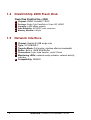
Introduction
Features .................................................
Specifications ........................................
VGA Interface .........................................
DiskOnChip 2000 Flash Disk ..................
Network Interface ...................................
C h a p t e r
2
5
6
7
8
8
Installation
2.1 Board Outline ......................................... 9
2.2 Connectors & Jumpers Summary ....... 10
2.3 Pin Assignments & Jumper Settings .... 11
J1 : LAN Connection . ...................................................... 11
J2 : RS485 Connection ................................................... 11
J3 : RESET ........................................................................ 11
J4 : IDE Connector .......................................................... 12
J5 : IDE LED ................................................................... 12
J7 : RS232/485 Select .................................................... 12
J8 : COM1Connection ................................................... 13
J9 : COM2 Connection .................................................. 13
J10 : Printer Connector .................................................. 13
J11: FDD Connector ........................................................ 14
J12 : LCD Connector ....................................................... 15
J6 : LCD Volts Selection ................................................. 15
J13 : USB Connector ........................................................ 16
J14 : Power Mode Sel. ................................................... 16
iii
J15 : VGA Connector ....................................................... 16
J16 : PS/2 Keyboard Connection ...................................... 16
J17 : Speaker ................................................................ 16
J19 : PC/104 Connector CN1 ........................................... 17
J21 : PC/104 Connector CN2 ........................................... 18
J18 : PS/2 Mouse Connection........................................... 19
ROM1: DOC Connector ................................................... 19
J22 : Power Connector .................................................. 19
2.4 DiskOnChip/Flash ROM Disk ................ 20
2.4.1 Setup a DiskOnChip
®
2000 Flash Disk ...................... 20
2.5 Watchdog Timer ................................... 21
C h a p t e r
3
SVGA Setup
3.1 Introduction.......................................... 25
3.1.1 Chipset .................................................................. 25
3.1.2 Display memory ...................................................... 25
3.2 Flat Panel BIOS and Wiring .................. 26
C h a p t e r
4
Network Interface
4.1 Introduction.........................................300
4.2 Software Support ................................300
W a r r a n t
y…………..……..……………….31
1
iv
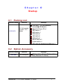
Chapter
0
Startup
0.1
Packing List
Product Name
ICOP-6070
0.2
Function
PC/104 Embedded
Vortex86 CPU
Module
Package
ICOP-6070 PC/104 Embedded
Vortex86 CPU Module
Manual & Drivers CD x 1
FDD cable x 1
HDD cable x 1
VGA cable x1
LAN cable x1
USB cable x1
RS232 cable x 2
Printer cable x 1
PS2 cable for Keyboard and Mouse x 2
Option Accessory
Product Name
Function
ICOP-0094
IDE Exchange Kit
Package
IDE 44 pin (2.0mm Pitch) to IDE 40 pin (2.54mm
Pitch), Board size:70 x 50 mm)
ICOP-6070 : PC/104 Embedded Vortex86 CPU Module
1
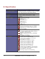
0.3 Specification
Features
2
ICOP-6070
Processor Chipset
DM&P(SiS)Vortex86 System-on-Chip CPU –166MHz
Real Time Clock with Lithium Battery Backup
Bus Interface
ISA and PC/104 Standard Compliant
Memory
Onboard 128MB SDRAM (optional 128MB)
BIOS
AMI BIOS
Multi I/O Chip
Enhanced IDE interface
RS232 port x1
RS232/485 port x1
Parallel port x1
FDD interface x1
USB port x2
Video Display
AGP Rev.2.0 Compliant
Shared system memory area up to 128MB.
Resolution up to 1,920Cx1,440 true colors
CRT/LCD display
LAN
Realtek 8100B single chip
Full-duplex transfer mode, doubles effective
bandwidth 16KB RAM buffer
NE2000 compatible with built-in 16KB RAM
buffer
Throughput 10/100Mbps
Connectors
2.0mm 44-pin box header for IDE
2.0mm 10-pin box header for RS-232 x2
2 pin header for RS-485
2.0mm 26-pin box header for Printer
2.0mm 34-pin box header for FDD
2.0mm 10-pin box header for USB
2.0mm 10-pin box header for VGA
2.0mm 8-pin header for Ethernet
2.0mm 44-pin box header for LCD connector
5-pin box header for AT-Keyboard connector
5-pin header for PS/2 Mouse
One 32-pin socket for for DiskOnChip
ICOP-6070 : Embedded Half-SizeVortex86 AIO SBC
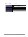
0.3 Specification … continuation
Watchdog Timer
Software Watchdog Timer
Three 8254 Compatible Programmable 16-bit
Counters. From 30.5µs to 512 seconds
DiskOnChip
One socket for DiskOnChip 8MB~256MB
Power Requirement
Single Voltage +5V @1.2 A
Board Weight
100g
Board Size
90mm X 96mm
Operating Temperature
-20°C ~ +60°C
ICOP-6070 : PC/104 Embedded Vortex86 CPU Module
3
This page is intentionally left blank.
4
ICOP-6070 : Embedded Half-SizeVortex86 AIO SBC
Chapter
1
Introduction
1.1
Features
PC/104 Embedded Vortex86 CPU Module (90 x 96 mm)
DM&P Vortex86 System-On-Chip
CRT and Flat Panel Display interface
Onboard 128MB SDRAM (optional 128MB)
Enhanced IDE devices and FDD interface
One Bi-directional Parallel Port
RS-232/485 interface
Watchdog timer
Socket for DiskOnChip
Onboard Keyboard & Mouse connector
Onboard Ethernet, compatible with NE2000
Single voltage +5 V power connector
Operating temperature from –20°C 〜 +60°C
Board Support Package for Windows CE.NET and Windows XP Embedded
Accept custom modification
ICOP-6070 : PC/104 Embedded Vortex86 CPU Module
5
1.2 Specifications
Embedded CPU: DM&P Vortex86 System-on-Chip CPU – 166MHz,
Realtime clock, and watchdog timer.
BIOS: Y2K compliant AMI system BIOS
System Memory: Onboard 128MB SDRAM (optional 128MB)
Bus Interface: PC/104 ISA Bus Interface
Data Bus: 64-bit
Bus Speeds: PCI Bus – 33MHz
DMA Channels: 7
Interrupt Levels: 15
Enhanced IDE: supports one port and up to two hard drives or Enhanced
IDE devices of PIO mode 4. BIOS enabled/disabled
Watchdog Timer: generates either a RESET, NMI or an IRQ when your
application loses control over the system. Optionally the watchdog can
trigger a user specified interrupt. The watchdog is configurable from 30.5µs
to 512 seconds (in 30.5µs segments)
Real-time Clock: included in Vortex86 SOC with onboard lithium battery
backup for 10 years of data retention. CMOS data backup of BIOS setup
and BIOS default.
Keyboard and Mouse Connectors:Supports PS/2 Keyboard and mouse
Serial ports: Supports high speed RS-232 port, high speed RS-232/485
port (jumper selectable).
Floppy Disk Drive Interface: supports up to two floppy drives, 5¼“ (360 KB
or 1.2 MB) and 3½ “ (720 KB, 1.44 MB). BIOS enabled / disabled
Bi-directional Parallel Port: supports SPP, EPP and ECP mode. BIOS
enabled/disabled
Environmental and Power
Power Requirements: single voltage +5 V @ 1.2A
Board Dimensions: 90 (L) x 96 (W) mm.
Board Weight :100 g
Extended Operating Temperature: -20°C ~+60 °C
6
ICOP-6070 : Embedded Half-SizeVortex86 AIO SBC
1.3
VGA Interface
Chipset: DM&P Vortex86 SOC
Memory: Shared system memory up to 128MB
System Bus: 33-bit PCI bus
Panel Data Bus: 24-bit
Display: CRT and LCD Flat Panel
Compliance:
- AGP 2.0 / 4X Compliant / Fully DirectX 8 Compliant
- Built-In DVI / DSTN / VIP interface
- Cooperates with “Video Bridge” to support NTSC/PAL TV / Digital LCD
Monitor / Secondary CRT Monitor output
Digital Output:
- Supports VESA Standard Super High Resolution Graphic Modes
- 640x480 16/256/32K/64K/16M Colors 160 Hz NI
Supported Flat Panels:
- PVI 6.4” TFT LCD panel P/N: V16C6448AC
- SHARP 6.4” TFT LCD panel P/N: LQ64D341
(HIROSE DF9BA-31P-1V)
- NEC 6.5” TFT Color LCD panel P/N: NL6448BC20-08
(HIROSE DF9B-31P-1V)
ICOP-6070 : PC/104 Embedded Vortex86 CPU Module
7
1.4
DiskOnChip 2000 Flash Disk
Flash Disk DiskOnChip ® 2000
Chipset: DM&P Vortex86 SOC
Package: Single Chip FlashDisk in 32-pin DIP JEDEC
Capacity: 8-256 MByte capacity
Data Reliability: ECC/EDC error correction
Memory Window: 8 Kbyte
1.5
Network Interface
Chipset: Realtek 8100B single chip
Type: 10/100BASE-T
Transfer Mode: Full duplex, doubles effective bandwidth
Buffer: Built-in 16KB RAM Buffer.
Connectors: 8-pin male header , pitch 2.0mm
Monitoring LEDs: network ready indicator, network activity
indicator
Compatibility: NE2000
8
ICOP-6070 : Embedded Half-SizeVortex86 AIO SBC
Chapter
2
Installation
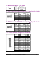
2.1
Board Outline
ICOP-6070 : PC/104 Embedded Vortex86 CPU Module
9
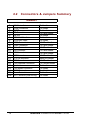
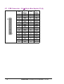
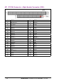
2.2
Connectors & Jumpers Summary
SUMMARY
J1:
J2:
J3:
J4:
J5:
J6:
J7:
J8:
J9:
J10:
J11:
J12:
J13:
J14:
J15:
J16:
J17:
J18:
LAN Connection
RS485 Connection
RESET
IDE Connector
IDE LED
LCD Volts Selection
RS232/485 Select
COM1 Connection
COM2 Connection
Printer Connector
FDD Connector
LCD Connector
USB Connector
CPU Fan connector
VGA Connector
PS/2 Keyboard Connection
Speaker
PS/2 Mouse Connection
J19,J21: PC104 Connector
J22: Power Connector
ROM1: DOC Connector (DiskOnChip)
10
Pin Header
Pin Header
Pin Header
2.0 ∅Box Header
Pin Header
Pin Header
Pin Header
2.0 ∅Box Header
2.0 ∅Box Header
2.0 ∅Box Header
2.0 ∅Box Header
2.0 ∅Box Header
2.0 ∅Box Header
Molex Box Header
2.0 ∅Box Header
2.0 ∅Molex Header
Pin Header
Pin Header
Box Header
Pin Header
Pin Header
ICOP-6070 : Embedded Half-SizeVortex86 AIO SBC
2.3 Pin Assignments & Jumper Settings
J1 : LAN Connection - 8-pin Header
Pin #
1
3
5
7
Signal
Name
TX+
RX+
CT/CMT
CT/CMT
Pin #
2
4
6
8
Signal
Name
TXCT/CMT
RXCT/CMT
J2 : RS485 Connection- 2.54 ∅ 2-pin Molex Header
Pin #
1
2
Signal
Name
RS485+
RS485-
J3 : RESET - 2-pin Header
Pin #
1
2
Signal
Name
PWROK
GND
ICOP-6070 : PC/104 Embedded Vortex86 CPU Module
11
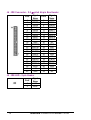
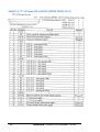
J4 : IDE Connector - 2.0 ∅ pitch 44-pin Box Header
Pin #
1
3
5
7
9
11
13
15
17
19
21
23
25
27
29
31
33
35
37
39
41
43
Signal
Name
IDERSTIDED7
IDED6
IDED5
IDED4
IDED3
IDED2
IDED1
IDED0
GND
IDEREQ
IDEIOWIDEIORICHRDY
IDACKIDEIRQ
IDESA1
IDESA0
IDECS-0
DASP
VCC
GND
Pin #
2
4
6
8
10
12
14
16
18
20
22
24
26
28
30
32
34
36
38
40
42
44
Signal
Name
GND
IDED8
IDED9
IDED10
IDED11
IDED12
IDED13
IDED14
IDED15
NC
GND
GND
GND
GND
GND
NC
CBLID
IDESA2
IDECS-1
GND
VCC
NC
J5 : IDE LED - 2-pin Header
Pin #
1
2
12
Signal
Name
VCC
DASP
ICOP-6070 : Embedded Half-SizeVortex86 AIO SBC
J7 : RS232/RS485 Select - 3-pin Header
Pin #
1-2
2-3
Signal Name
COM2 RS232
RS485
J8 : COM1 Connection (RS-232 Connector) - 2.0 ∅ 10-pin Box Header
Pin #
1
3
5
7
9
Signal
Name
DCD1
TXD1
GND
RTS1
RI1
Pin #
2
4
6
8
10
Signal
Name
RXD1
DTR1
DSR1
CTS1
NC
J9 : COM2 Connection (RS-232 Connector) - 2.0 ∅ 10-pin Box Header
Pin #
1
3
5
7
9
Signal
Name
DCD2
TXD2
GND
RTS2
RI2
Pin #
2
4
6
8
10
Signal
Name
RXD2
DTR2
DSR2
CTS2
NC
J10 : Printer Connector - 2.0 ∅ 26-pin Box Header
Pin #
1
3
5
7
9
11
13
15
17
19
21
23
25
Signal
Name
STBPD1
PD3
PD5
PD7
BISY
SLCT
ERRSLINGND
GND
GND
GND
Pin #
2
4
6
8
10
12
14
16
18
20
22
24
26
ICOP-6070 : PC/104 Embedded Vortex86 CPU Module
Signal
Name
PD0
PD2
PD4
PD6
ACKPE
AFDPRINITGND
GND
GND
GND
NC
13
J11 : FDD Connector - 2.0 ∅ 34-pin Box Header (17x2)
Pin #
1
3
5
7
9
11
13
15
17
19
21
23
25
27
29
31
33
14
Signal
Name
GND
GND
GND
GND
GND
GND
GND
GND
GND
GND
GND
GND
GND
GND
GND
GND
GND
Pin #
2
4
6
8
10
12
14
16
18
20
22
24
26
28
30
32
34
Signal
Name
DENSEL
NC
NC
INDEX\
MTRO\
DS1\
DS0\
MTR1\
DIR\
STEP\
WD\
WG\
TR0\
WP\
RD\
HDSEL\
DSKCHG\
ICOP-6070 : Embedded Half-SizeVortex86 AIO SBC
J12 : LCD Connector - 2.0 ∅ pitch 44-pin Box Header
Pin #
Signal
Name
Pin #
Signal
Name
1
3
5
7
9
11
13
15
17
19
21
23
25
27
29
31
33
35
37
39
41
43
LCDVCC
VAD0
VAD2
VAD4
VAD6
VAD8
VAD10
GND
UD5
UD7
VBD0
VBD2
VBD4
VBD6
VBD8
VBD10
GND
PLDXCLK
VADE
AHSYNC
AVSYNC
DISPOFF
2
4
6
8
10
12
14
16
18
20
22
24
26
28
30
32
34
36
38
40
42
44
LCDVCC
VAD1
VAD3
VAD5
VAD7
VAD9
VAD11
UD4
UD6
GND
VBD1
VBD3
VBD5
VBD7
VBD9
VBD11
GND
VBGCLK
VBDE
VBHSYNC
VBVSYNC
VDDEN
J6: LCD Volts Selection - 3-pin Header
Pin #
1-2
2-3
Signal
Name
+5V
+3.3V
DIGITAL RGB
SISSED
DSTN
18-BIT 24-BIT
CONN.
VAD0
VAD1
VAD2
VAD3
VAD4
VAD5
VAD6
VAD7
VAD8
VAD9
VAD10
VAD11
LD0
LD1
LD2
LD3
LD4
LD5
LD6
LD7
UD0
UD1
UD2
UD3
VBD0
VBD1
VBD2
VBD3
VBD4
VBD5
VBD6
VBD7
VBD8
VBD9
VBD10
VBD11
UD4
UD5
UD6
UD7
G2
G3
G4
G5
R0
R1
R2
R3
R4
R5
B0
B1
B2
B3
B4
B5
G0
G1
G4
G5
G6
G7
R0
R1
R2
R3
R4
R5
R6
R7
B0
B1
B2
B3
B4
B5
B6
B7
G0
G1
G2
G3
UD4
UD5
UD6
UD7
PLDXCLK SHFCLK
VADE
MOD/LDE
VAHSYNC LP/HYSNC
VHVSYNC FLM/VYSNC
DISOFF ENBT
XCLK
DEN
VBDE
VBHSYNC
HSYNC
VBVSYNC
VSYNC
VDDEN VDDEN VDDEN
VBGCLK
ICOP-6070 : PC/104 Embedded Vortex86 CPU Module
15
XCLK
DEN
HSYNC
VSYNC
VDDEN
J13 : USB Connector - 2.0 ∅ pitch 10-pin Box Header
Pin #
1
3
5
7
9
Signal
Name
VCC
-DATA1
+DATA1
GND
GND
Pin #
2
4
6
8
10
Signal
Name
VCC
-DATA0
+DATA0
GND
GND
J14 : CPU FAN - 2-pin Molex Header
Pin #
1
2
Signal
Name
VCC
GND
J15 : VGA Connector - 2.0 ∅ 10-pin Box Header
Pin #
1
3
5
7
9
Signal
Name
ROUT
GOUT
BOUT
HSYNC
VSYNC
Pin #
2
4
6
8
10
Signal
Name
GND
GND
GND
GND
GND
J16 : PS/2 Keyboard Connection - 5-pin Molex Header
Pin #
1
2
3
4
5
Signal Name
KBCLK
KBDAT
NC
GND
SB 5V (VCC)
J17 : Speaker - 2-pin Header
Pin #
1
2
16
Signal
Name
SPKR
VCC
ICOP-6070 : Embedded Half-SizeVortex86 AIO SBC
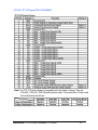
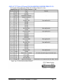
J19 : PC/104 Connector - 64-pin Header Connector (CN1)
1
3
5
7
9
11
13
15
17
19
21
23
25
27
29
31
33
35
37
39
41
43
45
47
49
51
53
55
57
59
61
63
IOCHCHK *
SD7
SD6
SD5
SD4
SD3
SD2
SD1
SD0
IOCHRDY
AEN
SA19
SA18
SA17
SA16
SA15
SA14
SA13
SA12
SA11
SA10
SA9
SA8
SA7
SA6
SA5
SA4
SA3
SA2
SA1
SA0
GND
2
4
6
8
10
12
14
16
18
20
22
24
26
28
30
32
34
36
38
40
42
44
46
48
50
52
54
56
58
60
62
64
ICOP-6070 : PC/104 Embedded Vortex86 CPU Module
GND
RESETDRV
+5V
IRQ9
-5V
DRQ2
-12V
ENDXFR *
+12V
(KEY)
SMEMW *
SMEMR *
IOW *
IOR *
DACK3 *
DRQ3
DACK1 *
DRQ1
REFRESH *
SYSCLK
IRQ7
IRQ6
IRQ5
IRQ4
IRQ3
DACK2 *
TC
SALE
+5V
OSC
GND
GND
17
J21 : PC/104 Connector - 40pin Header Connector (CN2)
1
3
5
7
9
11
13
15
17
19
21
23
25
27
29
31
33
35
37
39
18
GND
MEMCS16 *
IOCS16 *
IRQ10
IRQ11
IRQ12
IRQ15
IRQ14
DACK0 *
DRQ0
DACK5 *
DRQ5
DACK6 *
DRQ6
DACK7 *
DRQ7
+5V
MASTER *
GND
GND
2
4
6
8
10
12
14
16
18
20
22
24
26
28
30
32
34
36
38
40
GND
SBHE *
LA23
LA22
LA21
LA20
LA19
LA18
LA17
MEMR *
MEMW *
SD8
SD9
SD10
SD11
SD12
SD13
SD14
SD15
(KEY)
ICOP-6070 : Embedded Half-SizeVortex86 AIO SBC
J18 : PS/2 Mouse Connection- 5-pin Header
Pin #
1
2
3
4
5
Signal Name
PMCLK
PMDAT
NC
GND
SB 5V (VCC)
J22 : Power Connector - 2-pin Header
Pin #
1
2
Signal
Name
SB5V
GND
ROM1(DiskOnChip): DOC Connector – 32-pin Grid hole DIP Socket
Pin #
1
3
5
7
9
11
13
15
17
19
21
23
25
27
29
31
Signal
Name
NC
NC
XA7
XA5
XA3
XA1
XD0
XD2
XD3
XD5
XD7
XA10
XA11
XA8
NC
MWTCL
Pin #
2
4
6
8
10
12
14
16
18
20
22
24
26
28
30
32
ICOP-6070 : PC/104 Embedded Vortex86 CPU Module
Signal
Name
NC
XA12
XA6
XA4
XA2
XA0
XD1
GND
XD4
XD6
ROMCS1
MDRCL
XA9
NC
NC
VCC
19
2.4
DiskOnChip Flash Disk
2.4.1 Setup a DiskOnChip
®
2000 Flash Disk
Installation Instructions
1. Make sure the power of ICOP-6070 is turned OFF.
2. Plug the DiskOnChip 2000 device into its socket. Verify the mounting orientation of the
DiskOnChip 2000 is correct (DiskOnChip 2000 pin 1 must be aligned with pin 1 of the
socket).
3. Turn on the power of the system, and you may observe the messages displayed by
the DiskOnChip 2000 when its drivers are automatically loaded into system’s memory.
Start Address is assigned and fixed at “0E0000 HEX”.
4. If the DiskOnChip 2000 is the only disk in the system, it will appear as the first disk
(drive C: in DOS).
5. If there are more disks besides the DiskOnChip 2000, the DiskOnChip 2000 will
appear by default as the last drive.
6. If you want the DiskOnChip 2000 to be bootable: a - copy the operating system files
into the DiskOnChip by using the standard DOS command (for example: sys d:) b The DiskOnChip should be the only disk in the systems or should be configured as the
first disk in the system (c: ) using the DUPDATE utility
For more information on DiskOnChip2000 technology, visit M-Systems Web site –
http:// www.m-sys.com where you can find Utilities Manual, Data Sheets and Application
Notes. In addition, you can find the lasted DiskOnChip 2000 S/W Utilities.
20
ICOP-6070 : Embedded Half-SizeVortex86 AIO SBC
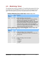
2.5
Watchdog Timer
The watchdog timer work flow of Vortex86 is: If the watchdog timer expires the first time,
the expired event will set SFTMR0_STS and timer will reload its inital value and count
again. If the timer expire the second time, the expired event will set SFTMR1_STS.
Software Watchdog Timer Initial Value: Default Value: FFh
I/O
Bit Access Description
Address
84Ah
7:0 R/W
Software Watchdog Timer Initial Value
Writing to this register will reload the software watchdog
timer with the value specified in this register. If the
software watchdog timer expires the first time, the expired
event will set the SFTMR0_STS and the timer will reload
its initial value and count again. If the timer expire the
second time, the expired event will set the SFTMR1_STS.
The timer value can't be read from this field.
Software Watchdog Timer Control Register: Default Value: 00h
I/O
Bit Access Description
Address
84Bh
7
R/W
Software Watchdog Timer Counting Enable
The software watchdog timer will start to count when this
bit is set to one.
6
RO
Reserved
5:4 R/W
Software Watchdog Timer Clock Select
00 : 4 ms
01 : 1 second
10 : 1 minute
11 : 1 hour
ICOP-6070 : PC/104 Embedded Vortex86 CPU Module
21
3:2 R/W
Software Watchdog Timer Expiration Event 1 Routing
Select
When SFTMR1_STS is set to one, an
SMI#/SFTIRQ/PCIRST# will be generated according to the
following combination.
00 : No effect
01 : SMI#
10 : SFTIRQ
11 : PCIRST#
1:0 R/W
Software Watchdog Timer Expiration Event 0 Routing
Select
When SFTMR0_STS is set to one, an
SMI#/SFTIRQ/PCIRST# will be generated according to the
following combination.
00 : No effect
01 : SMI#
10 : SFTIRQ
11 : PCIRST#
Legacy Event Status Register: Default Value: 00h
I/O
Bit Access Description
Address
841h
22
7
R/WC Software Watch Dog Timer Event 1 Status
(SFTMR1_STS)
This bit is set when the software watchdog timer expires
the second time. This status bit does not have its
corresponding enable bit and can survive under PCIRST#.
6
R/WC Software Watch Dog Timer Event 0 Status
(SFTMR0_STS)
This bit is set when the software watchdog timer expires
the second time. This status bit does not have its
corresponding enable bit and can survive under PCIRST#.
ICOP-6070 : Embedded Half-SizeVortex86 AIO SBC
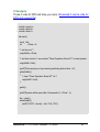
C Example
Those C code for DOS will show you more: (Download C source code for
DOS and execute file)
#include <conio.h>
#include <stdio.h>
#include <time.h>
void main()
{
clock_t clk;
int
nTime = 5;
/* set time out */
outp(0x84a, nTime);
/* set timer clock to 1 second and "Timer Expiration Event 0/1" to reset system.
*/
outp(0x84b, 0x9c);
printf("Press any key to stop clearing watchdog timer status...\n");
while(!kbhit())
{
/* clear "Timer Expiration Event 0/1" bit */
outp(0x841, 0xc0);
}
getch();
printf("System will be reset after %d seconds.\n", nTime * 4);
clk = clock();
while(!kbhit())
printf("%2.2f\r", (clock() - clk) / CLK_TCK);
}
ICOP-6070 : PC/104 Embedded Vortex86 CPU Module
23
Assembler Example code
mov dx,84ah ; set timeout = 20 second
mov al,5
out dx,al
mov dx,84bh ; set timer clock to 1 second and "Timer Expiration Event 0/1" to
reset system.
mov al,9ch
out dx,al
; clearing watchdog timer status
mov dx,841h
mov al,0c0h
out dx,al
24
ICOP-6070 : Embedded Half-SizeVortex86 AIO SBC
Chapter
3
SVGA Setup
3.1
Introduction
The ICOP-6070 offers high performance/low cost Vortex SoC (System on Chip) solution
that integrates a x86 compatible processor, high performance North Bridge, advanced
hardware GUI engine and Super-South bridge into a single chipset – this SoC design
supports the now PC technology, USB, Legacy Removal, CIR, Memory Stick, Smart Card
and Slotless Design for a variety of Industrial Applications covering automation, data
acquisition, internet communication, and other information exchange devices. It also has a
built-in VGA controller.
3.1.1 SoC Chipset
The embedded video uses the integrated Ultra-AGP VGA controller for Hardware
2D/video/Graphics Accelerators, this board supports conventional analog CRT monitor or
flat panel. It is both AGP 4X / Fully DirectX 8 Compliant. It also provides Monitor /
Secondary CRT Monitor output. This video SVGA controller supports conventional analog
CRT monitor or flat panel. In addition, it also supports interlaced and non-interlaced analog
monitors (color and monochrome VGA) in high-resolution modes while maintaining
complete IBM VGA compatibility. Multiple frequency (multi-sync) monitors are handled as if
they were analog monitors.
3.1.2 Display memory
The VGA controller can drive CRT displays or color panel displays with resolutions up to
1920 x 1440 at 256 colors (True colors). It supports Shared System Memory up to 128
MB.
ICOP-6070 : PC/104 Embedded Vortex86 CPU Module
25
3.2
Flat Panel BIOS Wiring
The ICOP-6070 offers high performance/low cost Vortex SoC (System on Chip) solution
that. integrates a x86 compatible processor, high performance North Bridge, advanced
hardware GUI engine and Super-South bridge into a single chipset – this SoC design
supports the now PC technology, USB, Legacy Removal, CIR, Memory Stick, Smart Card
and Slotless Design for a variety of Information Exchange applications. It also has a built-in
VGA controller. Shown on next page are the Supported Flat Panels:
- PVI 6.4” TFT LCD panel P/N: V16C6448AC
- SHARP 6.4” TFT LCD panel P/N: LQ64D341 (HIROSE DF9BA-31P-1V)
- NEC 6.5” TFT Color LCD panel P/N: NL6448BC20-08 (HIROSE DF9B-31P-1V)
26
ICOP-6070 : Embedded Half-SizeVortex86 AIO SBC
- PVI 6.4” TFT LCD panel P/N: V16C6448AC
TFT-LCD Panel Driving
Note: The TFT-LCD panel display is compatible with four kinds of timing. They are
VGA-480, VGA-400, VGA-350 and freedom mode. The polarization of Hsync and
Vsync determine the timings.
ICOP-6070 : PC/104 Embedded Vortex86 CPU Module
27
- SHARP 6.4” TFT LCD panel P/N: LQ64D341 (HIROSE DF9BA-31P-1V)
28
ICOP-6070 : Embedded Half-SizeVortex86 AIO SBC
- NEC 6.5” TFT Color LCD panel P/N: NL6448BC20-08 (HIROSE DF9B-31P-1V)
ICOP-6070 : PC/104 Embedded Vortex86 CPU Module
29
Chapter
4
Network Interface
4.1
Introduction
4.2
Software Support
The Realtek RTL-8100B 10/100Mbps Ethernet controller board supports both
10/100BASE-T and Coax 10Base-2 ‘BNC’ connectors, and allows direct connection to your
10/100Mbps Ethernet based Local Area Network for full interaction with local servers, wide
area networks such as the Internet.
I/O and IRQ settings can be done by software with the supplied utility software, or it can be
set for Plug and Play compatibility. The controller supports : Full-Duplex Ethernet function
to double channel bandwidth, auto media detection.
On-board EEPROM (93C46) programming
Setup/Diagnostic program for DOS
Help utility for easy installation
RPL boot ROM for Novell Netware, Microsoft NT
NDIS2 (DOS,OS/2,Lantastic,WFW3.1¡K¡K)
NDIS3,NDIS4,NDIS5 for WIN95,98,NT3.51,4.0,5.0,WFW3.11
Netware 16-bit ODI driver for DOS,OS/2 and 32-bit ODI driver for Netware
3.x,4.x,5.0 Server
Packet driver for UNIX Client
SCO Unix driver
Linux driver
All operating systems that support standard NE2000
30
ICOP-6070 : Embedded Half-SizeVortex86 AIO SBC
Warranty
This product is warranted to be in good working order for a period of one year from the date of
purchase. Should this product fail to be in good working order at any time during this period, we will,
at our option, replace or repair it at no additional charge except as set forth in the following terms.
This warranty does not apply to products damaged by misuse, modifications, accident or disaster.
Vendor assumes no liability for any damages, lost profits, lost savings or any other incidental or
consequential damage resulting from the use, misuse of, originality to use this product. Vendor will
not be liable for any claim made by any other related party. Return authorization must be obtained
from the vendor before returned merchandise will be accepted. Authorization can be obtained by
calling or faxing the vendor and requesting a Return Merchandise Authorization (RMA) number.
Returned goods should always be accompanied by a clear problem description.
ICOP-6070 : PC/104 Embedded Vortex86 CPU Module
31