1
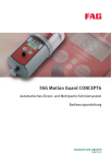
FAG Motion Guard CONCEPT6
Automatic single-point and multiple-point lubrication system
User manual
FAG Motion Guard CONCEPT6
Page
Features
Safety guidelines
Technical data
Assembly and mounting
Application................................................................................
3
Scope of delivery.......................................................................
3
Legal requirements....................................................................
4
Responsible persons.................................................................
5
Principles ..................................................................................
5
Key data ....................................................................................
6
Design.......................................................................................
7
Function ....................................................................................
7
Operating conditions.................................................................
8
Wall-mounting the drive ............................................................ 10
Mounting the lubricator............................................................. 11
Display and controls
Function displays ...................................................................... 13
Menu control keys ..................................................................... 14
Calculation of the
dispensing time
................................................................................................. 15
Initial operation and handling
Operation.................................................................................. 16
Deactivation.............................................................................. 17
Display settings and contents
Low-temperature deactivation ................................................... 20
Calculating the remaining running time ..................................... 21
Changing the LC unit
................................................................................................. 22
Error messages and
troubleshooting
................................................................................................. 24
Accessories and service
................................................................................................. 25
EU Declaration of Conformity
................................................................................................. 27
Function and operation in brief
................................................................................................. 28
2
BA 10
Schaeffler Group Industrial
FAG Motion Guard CONCEPT6
Features
Attention!
Application
Attention!
Scope of delivery
This user manual describes how to work safely on and with
the automatic lubricator FAG Motion Guard CONCEPT6.
The safety guidelines must be observed.
Any persons working on and with the lubricator must have the user
manual available for their work and must observe the relevant
information and guidelines.
The user manual must always be complete and in a fully legible
condition.
The relevant disposal guidelines must be observed.
From this point onward, the FAG Motion Guard CONCEPT6 is referred
to as the lubricator and the lubricant cartridge as the LC unit.
The lubricator is clearly identified by a sticker on the drive unit and
the LC unit.
It is intended for machinery and plant where lubrication is to
be carried out continually over the pre-calculated period.
The lubricator supplies one or more lubrication points with
grease at a pressure of up to max. 25 bar.
Characteristic areas of application include the lubrication points on
rolling and plain bearings, drive and conveyor chains,
guidance systems, open gearboxes and seals.
The lubricator must only be used for the purposes stated in the
order and confirmed by Schaeffler KG and in accordance with
the conditions of use, settings and variations described in this
user manual.
The lubrication system must only be equipped with connections and
pressure-resistant feed lines from Schaeffler KG.
The lubricator must be protected against chemically aggressive
ambient media.
Lubricator, Figure 1.
Schaeffler Group Industrial
00014E7E
Figure 1
Delivery scope of lubricator
(lubricator with holder, battery,
cover and user manual)
BA 10
3
FAG Motion Guard CONCEPT6
Figure 2
LC unit
(available in two sizes)
Legal requirements
Liability
Attention!
4
BA 10
00014E7F
Attention!
LC unit:
The lubricator can be used with two LC units of different sizes.
The volume of the LC unit and the grease fill correspond to
the specific order.
The delivery should be checked as soon as it is received.
Schaeffler KG accepts no liability for any defects that are
the subject of subsequent complaints.
The packaging and the device should be checked immediately
for any damage during transit. The carrier should be informed of any
damage without delay and the damage should be photographed
if necessary.
The LC unit and suitable grease must be ordered separately.
The information, data and guidelines given in the user
manual were current at the time of editorial approval.
The data, illustrations and descriptions cannot be used
as grounds for any claims relating to lubricators that have
already been delivered.
Schaeffler KG accepts no liability for any damage or operational
malfunctions that occur as a result of improper use or unauthorised
changes to the drive unit or LC unit.
This also applies to incorrect work on or with the lubricator,
errors in use or adjustment, incorrect variation sizes of the lubricator
or a failure to observe the usser manual.
Schaeffler Group Industrial
Safety guidelines
Responsible persons
Operator
Attention!
Qualified personnel
Principles
Attention!
Schaeffler Group Industrial
The operator is the natural or juristic person that uses the lubricator
or on whose instruction the lubricator is used.
The operator or his safety co-ordinator are responsible for
compliance with all relevant specifications, guidelines and
regulations.
All work on and with the lubricator may only be carried out by
qualified personnel.
Persons that are authorised by the person responsible for safety
of the plant, on the basis of their experience and knowledge,
to carry out the activities required in the specific case.
The lubricator must be filled with the correct grease and adjusted
such that, when it is correctly adjusted and mounted and used as
specified, it functions without defects and does not cause any
hazards. This also applies to the interaction with the complete plant
and the points to be lubricated.
Material damage that could arise due to failure of the lubricator
must be prevented by suitable measures.
All retrofitting, modification and conversion of the lubricator is
prohibited.
While working on machinery and plant, the safety guidelines and
user manuals of the manufacturers must be observed.
The LC unit must not be opened or refilled under any circumstances.
Keep grease away from eyes, skin and clothing.
The safety data sheets for the greases must be observed.
Only original LC units from Schaeffler KG may be used.
BA 10
5
FAG Motion Guard CONCEPT6
Technical data
Key data
Description
CONCEPT6 250
CONCEPT6 500
Volume of LC unit
250 cm2
500 cm2
Length (L)
210 mm
260 mm
Diameter (D)
92 mm
92 mm
Weight when empty
approx. 1,30 kg
approx. 1,37 kg
Weight when filled with
Arcanol MULTITOP
approx. 1,53 kg
approx. 1,82 kg
Dispensing time
1 day to 24 months
1 day to 12 months
Dispensing quantity per
lubrication impulse
0,5 cm3
Operating temperature
–20 °C to +60 °C
Maximum pressure build-up 25 bar
Hose length
(5 mm inside diameter)
Lubricants
A combination of these
maximum values is only
achievable at
temperatures ⬎20 °C.
Application is restricted
Greases up to
consistency class NLGI 2 at lower temperatures,
see Diagram 1, page 9.
max. 5 m
Power supply
■ from
0 °C to +60 °C
Battery set 3 V
(alkaline manganese, not rechargeable)
■ from –20 °C to +60 °C
Battery set LT 3 V
(lithium, not rechargeable)
Connecting thread
G3/8 external – G1/8 internal
Protection class
IP 54
2
1
Figure 3
Lubricator
6
BA 10
141 260
Diameter
Length
Schaeffler Group Industrial
Design
The lubricator components correspond to the state of technology
at the time of delivery and are always regarded as operationally
reliable.
The components, Figure 4:
■ Cover for the drive system ,
■ LC unit LC250 or LC500 containing lubricant ,
■ Battery set ,
■ Drive system , comprising a geared motor, pump,
plug for connection cable to optional lubricant distributor
C6-MP-DISTRIBUTOR and the electronic unit.
With the exception of the LC unit, all of the components can be
reused several times.
3
1
Cover
LC unit
Battery set
Drive system
2
4
Function
Schaeffler Group Industrial
141 259
Figure 4
Main components of
the FAG lubricator
The lubricator supplies the lubrication point with the required
quantity of grease at a pre-selectable time interval
(1 day up to 24 months).
The lubricant is transported from the LC unit into the drive unit by
a spindle-driven piston. The pump in the drive unit transports
the lubricant to the lubrication point at a pressure of up to maximum
25 bar.
The size of the LC unit and the dispensing time can be configured in
the drive unit
BA 10
7
FAG Motion Guard CONCEPT6
Operating conditions
Operating temperature
Ambient conditions
Storage
A uniform dispensing pattern and the build-up of pressure to a
maximum of 25 bar can only be ensured in the temperature range
of -20 °C to +60 °C, see Diagram 1, page 9.
If the individual components are fitted together correctly, the
lubricators are resistant to dust and spray water. However, the
sealing rings and plastics may be attacked by ambient media.
Lubricators must only be stored in interior rooms that are dry,
dust-free and protected against sunlight, at a storage temperature
of +15 °C to +25 °C. Under no circumstances should the cover
disk and the stopper be removed from the drive permanently, Figure 5, as this will run down the internal back-up
battery. The cover disk and the stopper may only be removed
immediately prior to initial operation.
1
2
Cover disk
Stopper
Drive
Figure 5
Drive unit
Attention!
8
BA 10
141 215
3
The LC unit can be stored for up to two years; the lubricant fill date
should be taken as the controlling factor. All other components –
with the exception of the battery set – should also be replaced after
a maximum of two years.
The battery set can be stored for a maximum of one year.
Do not store the drive and cover disk separately.
Schaeffler Group Industrial
Specifications
Range of application,
standard grease
Range of application,
low-temperature grease
Impermissible, outside of
the specifications
60
°C
50
140
°F
120
40
100
30
80
20
60
2
1
10
40
0
20
–10
3
0
–20
0
1
2
3
4
m
5
00014E87
Diagram 1
Relationship between operating
temperature and hose length
Hose length between 0 m and 5 m (inside diameter 5 mm),
operating temperature between –20 °C and +60 °C;
based on standard greases at Schaeffler KG.
Example
Attention!
Schaeffler Group Industrial
Examples of calculated values from Diagram 1:
■ The operating temperature is +5 °C.
Maximum hose lengths?
– Working across to the right from the “+5 °C” mark gives a
maximum hose length of 3 m for standard grease and a
maximum hose length of 5 m for low-temperature grease.
■ Hose feed line length 4 m.
Maximum operating temperatures?
– Working upwards from the “4 m” mark gives a maximum of
+10 °C for standard grease and a maximum of –5 °C for
low-temperature grease.
The diagram also shows that the maximum hose length of 5 m can
be used with standard grease within a temperature range of +15 °C
to +60 °C and with low-temperature grease between 0 °C and
+15 °C.
Schaeffler KG accepts no liability for applications which fall outside
of the specifications.
Schaeffler Customer Service must be contacted if the application
falls outside of the specifications in Diagram 1.
BA 10
9
FAG Motion Guard CONCEPT6
Assembly and mounting
Wall-mounting the drive
Attention!
Procedure for cases where direct fixing at the lubrication point is not
possible:
■ Screw the holder and drive to a carrier assembly on the device.
In the event of a metallic base material, use a minimum of three
hexagon head screws M6⫻25; hole pattern for the three fixing
screws in accordance with Figure 6 and the attached hole
template.
■ The lubrication points and the entire lubricant feed line must
be pre-greased using the same lubricant as that contained in the
LC unit (lubricant cartridges for manual grease guns are available
as accessories, page 25).
■ Connect the lubricant feed line (G3/8 external or G1/8 internal)
to the drive’s outlet and run this to the lubrication point.
If the thread does not match the connecting thread at the
lubrication point, use an appropriate reducer.
■ Length of the lubricant feed line, see Diagram 1, page 9.
Unwanted leakages can only be prevented by fitting connections
and lubricant feed lines correctly and securely.
1
141,5
Figure 6
Wall-mounting the drive
10
BA 10
2
2
1
45
1
141 261
3 hexagon head screws M6⫻25
for wall-mounting
2 hexagon head screws M6⫻16
for lubricator and holder
(maximum torque 3 Nm)
Schaeffler Group Industrial
Mounting the lubricator
Attention!
Insert the battery set into the battery compartment, Figure 7 .
Note the direction of the arrow on the battery set label.
Only battery sets from Schaeffler KG may be used.
Batteries should not be exposed to extreme heat or thrown into an
open fire.
The safety data sheets for batteries must be observed.
4
2
250
500
Teeth for positioning the LC unit
Contact bridge, no function
Drive catch for spindle drive
Battery compartment
3
141 262
1
Figure 7
Underside of the drive system
Insert the LC unit into the cover and remove the sealing cap,
Figure 8.
2
1
3
141 217
Cover
LC unit
Sealing cap
Figure 8
Composition of the LC unit
Schaeffler Group Industrial
BA 10
11
FAG Motion Guard CONCEPT6
Push the LC unit into the cover until the grease escapes, Figure 9 .
1
Figure 9
Preparing the LC unit
Attention!
141 218
Outlet opening
Position the LC unit and cover on the drive so that the catch locks
into place, Figure 7 , page 11, and the teeth, Figure 7 ,
page 11, engage with each other. Rotate the cover in a clockwise
direction until the bayonet catch locks into place, see Figure 10.
The LC unit must be connected to the drive immediately after
removing the cover disk and the sealing cap, Figure 8, page 11.
1
Cover containing LC unit
Drive
12
BA 10
141 263
2
Figure 10
Connect drive and LC unit
Schaeffler Group Industrial
The operating condition of the lubricator can be determined from
the green and red LEDs and from the display on the control unit,
Figure 11.
The settings for the lubricator can be performed using the keys und and monitored on the display. Error messages generated
when there is excessive pressure in the lubricant feed line for
example, are also displayed.
LC display
Red LED
“OFF/ON SELECT” key
FAG C6-MP-DISTRIBUTOR connector
(for up to 6 lubrication points)
Green LED
“MODE SAVE” key
1
2
Figure 11
Display and control keys
on the drive
6
3
4
5
141 264
Display and controls
4
Function displays
Display
LED signals
Schaeffler Group Industrial
The “--” display cannot be deactivated, irrespective of the condition
of the battery set. Settings, operating conditions and error
messages relating to the lubricator are shown on the display,
Figure 11 .
During defect-free operation, the display shows the residual volume
of the fitted LC unit in percent volume (% vol.).
The LEDs on the drive, Figure 11 and , are interpreted as
follows:
LED lit
Signal
Green
Flashing
every 10 seconds System running
Description
Red
Flashing
every 3 seconds
Error or malfunction
Green and red
Flashing
every 3 seconds
Replace LC unit immediately
Green
Continuous
Motor running;
dispensing operation
BA 10
13
FAG Motion Guard CONCEPT6
Short: Selection
Short: Change values
Long ⬎ 4 s: Switch to new mode,
store set values
Long ⬎ 4 s: Activate and deactivate,
return to previous mode,
delete last change
Figure 12
Functions of the control keys
(short or long keystroke)
14
BA 10
There are two keys on the control unit, Figure 11 and , page 13,
for setting and menu navigation.
■ The key “MODE SAVE” accesses the configuration menu,
changes the mode and saves the modified settings for further
operation.
■ The “ON/OFF SELECT” key is used
– for activation and deactivation
– to increase the dispensing time in days, weeks or months
by one calendar unit per keystroke, to change the LC unit,
to configure the outlets and to set the PIN.
MODE
SAVE
4
3
2
1
ON/OFF
SELECT
MODE
SAVE
ON/OFF
SELECT
141 265
Menu control keys
Schaeffler Group Industrial
Calculation of the
dispensing time
The dispensing time is set at six months by the factory.
The dispensing time for the lubrication point is based on
the information provided by the plant manufacturer
on the lubrication quantity required in cubic centimetres
(cm3/100 h) for 100 operating hours.
The dispensing time can then be calculated using the table.
Average dispensing quantity in cm3,
specified for the respective LC unit per 100 operating hours
Setting parameter Setting mode
Dispensing time
LC250 (250 cm3)
LC500 (500 cm3)
Days
Weeks
Months
Days
Weeks
Months
1
1041,7
148,8
34,3
2083,3
297,6
68,5
2
520,8
74,4
17,1
1041,7
148,8
34,3
3
347,2
49,6
11,4
694,4
99,2
22,8
4
260,4
37,2
8,6
520,8
74,4
17,1
5
208,3
29,8
6,9
416,7
59,5
13,7
6
173,6
24,8
5,7
347,2
49,6
11,4
7
148,8
21,3
4,9
297,6
42,5
9,8
8
130,2
18,6
4,3
260,4
37,2
8,6
9
115,7
16,5
3,8
231,5
33,1
7,6
10
104,2
14,9
3,4
208,3
29,8
6,9
11
94,7
13,5
3,1
189,4
27,1
6,2
12
86,8
12,4
2,9
173,6
24,8
13
80,1
11,4
2,6
160,3
22,9
–
14
74,4
10,6
2,4
148,8
21,3
–
15
69,4
9,9
2,3
138,9
19,8
–
16
65,1
9,3
2,1
130,2
18,6
–
17
61,3
8,8
2,0
122,5
17,5
–
18
57,9
8,3
1,9
115,7
16,5
–
19
54,8
7,8
1,8
109,6
15,7
–
20
52,1
7,4
1,7
104,2
14,9
–
21
49,6
7,1
1,6
99,2
14,2
–
22
47,3
6,8
1,6
94,7
13,5
–
23
45,3
6,5
1,5
90,6
12,9
–
24
43,4
6,2
1,4
86,8
12,4
–
25
41,7
–
–
83,3
–
–
26
40,1
–
–
80,1
–
–
27
38,6
–
–
77,2
–
–
28
37,2
–
–
74,4
–
–
29
35,9
–
–
71,8
–
–
30
34,7
–
–
69,4
–
–
5,7
The remaining running time of the lubricator must be recalculated
following one or more special dispensing operations, page 21.
This also applies to deactivation in the event of extended machinery
downtime. The remaining running time must be recorded in the
lubrication and maintenance plan. This task is made even easier by
the software FAG Motion Guard SELECT MANAGER. This can be
downloaded free of charge from the website www.fis-services.
Schaeffler Group Industrial
BA 10
15
FAG Motion Guard CONCEPT6
Initial operation and handling
Attention!
Operation
The following must be ensured before initial operation:
■ Is the lubricator outwardly intact?
■ Does the LC unit contain the right grease?
■ Has the cover disk, complete with stopper, been removed from
the drive?
■ Have all of the components been correctly fitted together and
secured?
Always check the lubricator settings before initial operation and
make corrections as necessary.
Work exactly to the user manual.
Upon initial operation, the pump system in the drive unit is pre-filled
with a universal grease. After approximately ten dispensing
operations, this fill is drained off and replaced with the grease from
the LC unit; perform special dispensing operations where
necessary.
Hold the “ON/OFF SELECT” key down for longer than 4 s.
The display , Figure 13, is replaced with the residual volume
display , for example “99 % VOL” for a new LC unit.
The green LED flashes. Then set the volume of the LC unit,
the dispensing time, the outlets for any connected
C6-MP-DISTRIBUTOR and the PIN using the keys on the display,
Figure 14, page 18.
1
2
Figure 13
Displays upon activation
141 224
Prior to activation
Following activation
Then perform a one-off special dispensing operation. The starting
up of the drive motor and the illumination of the green LED indicate
that the dispensing operation has begun. The residual volume of the
LC unit appears on the display, Figure 13 .
16
BA 10
Schaeffler Group Industrial
During operation
Special dispensing operations
Machinery downtime
Check regularly:
■ Seal integrity of the lubricator, the feed lines and the connections
■ Lubricant fill level
■ Correct position and finger tight screw mounting of all
components.
Calculate the modified dispensing time and incorporate this into
the remaining running time of the lubricator and into the lubrication
and maintenance plan.
Malfunctions
If the control system is showing a malfunction, the reason will
appear on the display. Further information is contained in the defect
table on page 24.
Deactivation
Hold the “ON/OFF SELECT” key down for longer than 4 s, until
the residual volume display Figure 13 , page 16, disappears and
is replaced with the display “--”. All lubricator settings remain
stored so that the program can continue from the point at which it
was stopped upon reactivation.
Schaeffler Group Industrial
BA 10
17
FAG Motion Guard CONCEPT6
Display settings and contents
The configuration menu should be worked through from top to
bottom and from left to right and corresponds to the process for
a deactivated lubricator. Configuration is also possible in an
activated state.
1
2
MODE
SAVE
3
4
5
MODE
SAVE
SELECT
MODE
SAVE
SELECT
MODE
SAVE
SELECT
MODE
SAVE
SELECT
MODE
SAVE
SELECT
MODE
SAVE
SELECT
MODE
SAVE
SELECT
MODE
SAVE
SELECT
MODE
SAVE
SELECT
MODE
SAVE
SELECT
6
7
Figure 14
Configuration menu settings
and displays
Configuration sections
18
BA 10
8
9
10
11
12
13
00014E88
Delivered condition of fitted LC unit
Time-setting and PIN-reset display
PIN entry, first digit
PIN entry, second digit
Select volume of the LC unit
Set month, weeks or days
Switching to days or weeks
Set outlets (with distributor only)
Outlet 1 activated
Outlet 2 activated
Change PIN, first digit (for initial
configuration or following PIN reset only)
Change PIN, second digit (for initial
configuration or following PIN reset only)
Configuration complete
MODE
SAVE
Function
Press for short
period
Press for long
period ⬎ 4 s
Signal
Go to
Symbol
Arrow pointing
downwards
Longer arrow
Symbol
⇒
Schaeffler Group Industrial
INTRO
Configuration menu
LC unit
Time
Outlets
INTRO provides information (INFO) and asks for the current PIN
(PIN entry). Changes are made in the configuration menu and its
sections (LC, time, outlets, PIN).
“ON/OFF SELECT” key for setting LC250 or LC500.
Setting in either months, weeks or days. Once the maximum setting
parameter has been reached, counting always starts again with the
digit 01. The last screen contents displayed are adopted by holding
down the “MODE SAVE” key for a long period.
The activation of outlets 1 to 6 is indicated by the filled squares.
If no FAG C6-MP-DISTRIBUTOR is connected, the configuration of
the outlets will have no effect.
PIN
A personal PIN protects the settings from unauthorised access.
The PIN can only be changed during the very first configuration or
following a PIN reset. The PIN reset (pressing the keys for a short
period: left-left-right-right-left in INTRO-Info menu) returns the
personal PIN to its delivered state of “00”. If the time display
disappears briefly, the reset has been successful. All other settings
remain unchanged.
Do not adopt changes in the
respective configuration section
If the settings in the currently displayed configuration section
(LC, time, outlets, PIN) are not to be adopted, the “ON/OFF SELECT”
key must be held down until the symbol (“--”) for “OFF” or the
residual volume in the LC unit appears in “% VOL”. All other
settings and previously adopted changes remain unaffected.
Automatic termination of the
configuration mode
If, during a period of 180 seconds, no key is activated in a
configuration section, the control system automatically reverts to
the previously set mode (“ON” or “OFF”), without adopting the
changes. All previously implemented settings and adopted changes
remain unaffected.
Schaeffler Group Industrial
BA 10
19
FAG Motion Guard CONCEPT6
Special dispensing operation
Activated lubricator
(“ON/OFF SELECT” key)
To carry out the special dispensing
operation, hold down both keys
at the same time
The option exists to perform a special dispensing operation
in order to supply a lubrication point with addititional lubricant.
This involves holding down the “MODE SAVE” and
“ON/OFF SELECT” keys for an equal length of time.
1
2
MODE
SAVE
ON/OFF
SELECT
Attention!
Low-temperature deactivation
Attention!
141 266
Figure 15
“Special dispensing operation”
function
The special dispensing operation can only take place at
a temperature of more than 0 °C (ice crystal, Figure 16, is not visible)
and if the lubricator is not dispensing at the exact same time.
There is a minimum period of 30 seconds between two special
dispensing operations. On each additional occasion that both keys
are held down for long periods, Figure 15 during this time, this is
registered and leads to further special dispensing operations.
A maximum of 5 special dispensing operations are stored by the
system.
The remaining running time, which has been reduced as a result of
the dispensed lubricant quantity, must be included in the
lubrication and maintenance plan.
The permissible temperature range of 0 °C to –19 °C is indicated by
a flashing ice crystal symbol, Figure 16. Within this temperature
range, the lubricator will continue to work without interruption.
Special dispensing operations cannot be performed within this
temperature range.
Flashing ice crystal indicates 0 °C to –19 °C
(shown here with 89 % vol. as an example)
Attention!
20
BA 10
141 227
Figure 16
“Low-temperature deactivation”
function
If the temperature drops to –20 °C or less, the lubricator shuts
down. The ice crystal symbol appears permanently;
the residual quantity in “% vol.” is still displayed.
No further lubricant is dispensed from this point onwards.
Damage may occur if appropriate measures are not taken.
If the temperature rises back to –19 °C, or higher to 0 °C,
the lubricator reactivates and the ice crystal symbol flashes.
Schaeffler Group Industrial
Calculating the remaining
running time
Attention!
All dispensing operations which have accumulated during
deactivation (with the exception of special dispensing operations)
are made good, whereby up to two additional dispensing operations
are performed for each planned dispensing operation.
The remaining running time must be recalculated and recorded
following each special dispensing operation and deactivation.
Remaining running time
R LZ =
SZ ⋅ RV
100
Definitions:
SZ: Dispensing time set for the lubricator (days, weeks, months)
RV: Displayed residual volume (% vol.)
RLZ: Remaining running time (days, weeks, months,
dependent on SZ)
Calculation example for remaining
running time
The lubrication point requires a dispensing quantity of 4,3 cm3 of
grease after every 100 hours. The lubricator and LC250 (250 cm3)
are set to a dispensing time of eight months, as prescribed.
After two months at a residual volume of 75 %, operation is
interrupted; the plant and consequently the lubricator remain
deactivated for six weeks.
Once the plant has been reactivated, when should the LC unit be
replaced?
Example
R LZ =
SZ ⋅ RV 8 ⋅ 75 600
=
=
=6
100
100 100
According to the formula, the changeover should take place after six
months.
Schaeffler Group Industrial
BA 10
21
FAG Motion Guard CONCEPT6
Changing the LC unit
Attention!
The simultaneous flashing of the red and green LED combined with
the empty level reading on the display, Figure 17, indicate that the
empty LC unit and the battery set must be replaced immediately.
The lubricator’s control system always assumes that a new,
complete LC unit is used and continues with the previous running
time setting.
The LC must not be opened or refilled under any circumstances.
Only new, completely filled FAG LC units should be used.
Use a new FAG battery set at the same time.
Protect the drive system and control circuit board against moisture.
The unit should only be changed in dry conditions.
When changing the LC unit for a different size, the appropriate cover
should be used.
If the setting on the display does not correspond to the size of the
fitted LC unit, this will lead to incorrect dispensing quantities and
displays.
Dispose of old parts in accordance with the applicable regulations.
Figure 18
LC unit with volume of 250 cm3
or 500 cm3
22
BA 10
The volume of the LC unit is selected in the configuration menu,
page 18, by using the two control keys on the drive.
Two settings are possible, Figure 18.
141 229
Setting the volume
141 228
Figure 17
Change the LC unit
Display “00 %vol.”
Schaeffler Group Industrial
Procedure for replacing the LC unit
Schaeffler Group Industrial
Work steps:
■ Rotate the cover on the drive in an anti-clockwise direction and
remove.
■ Remove the empty LC unit; “LC” will appear on the display and
the red LED will flash.
■ Remove the sealing cap from the new LC unit, Figure 8, page 11.
■ Push the LC unit into the cover until the lubricant works its way
out of the outlet, Figure 9, page 12.
■ Fit the LC unit, rotate until the catch locks into place and
the teeth of the LC unit and the drive engage with each other.
The lubricator's control system automatically detects the new LC
unit. “--” appears in the display if the device was previously
deactivated, or “99 % vol.” if the device was activated prior to
the changeover.
■ If the lubricator was activated, it will continue to work with the
previous running time setting. If not, activate.
■ Where necessary, change the configuration of the lubricator,
page 18.
BA 10
23
FAG Motion Guard CONCEPT6
Error messages and
troubleshooting
Troubleshooting
Any function defects are detected by the electronic control
system and shown on the display. Whilst a defect is being
displayed, the system will shut down until the defect has been
eliminated and the error message has been acknowledged.
Exception: Displays F1 to F6 for connected distributor, see user
manual for FAG C6-MP-DISTRIBUTOR. The error messages are
acknowledged and removed by pressing the “ON/OFF SELECT” key.
For each error message displayed, the red LED will also flash.
Localize and eliminate possible defect sources using the table.
Display reading
Defect
Possible cause
Remedy
E1
Lubricator has
been deactivated
Excessive motor
current,
outlet is blocked
Remove blockage,
acknowledge
defect by holding
down the
“ON/OFF SELECT”
key for a long
period
Battery set empty
Use new battery
set and fit full
LC unit
E4
Lubricator has
been deactivated
Drive mechanics
defective
Replace drive
LC
System is not
detecting an
LC unit
LC unit missing
Fit full LC unit
use new
battery set
Lo
No power supply
Battery set empty
or missing
completely
Use new battery
set and fit full
LC unit
Schaeffler Customer Service will provide assistance if a problem
occurs which is not included in the overview.
24
BA 10
Schaeffler Group Industrial
Accessories and service
Replacement parts
Due to the high pressure of up to 25 bar, only original replacement
parts should be used. This applies in particular to lubricant feed
lines.
All FAG replacement parts conform to the technical requirements.
5
1
3
Figure 19
Replacement parts
2
141 267
6
4
No. Description
Ordering designation
LC250 with 250 cm³ of special
lubricant Arcanol MULTITOP
ARCALUB-C6.LC250-MULTITOP
LC250 with other Arcanol greases
or special greases
LC250 with 500 cm³ of special
lubricant Arcanol MULTITOP
LC500 with other Arcanol greases
or special greases
Cover for LC250 made from
transparent plastic
Available by agreement
ARCALUB-C6.LC500-MULTITOP
Available by agreement
ARCALUB-C6.CAP250
Cover for LC250 made from aluminium Available by agreement
(for lubricants containing ester)
Cover for LC500 made from
transparent plastic
ARCALUB-C6.CAP500
Cover for LC500 made from aluminium Available by agreement
(for lubricants containing ester)
Schaeffler Group Industrial
Battery set (0 °C to +60 °C)
ARCALUB-C6.BATTERY
Battery set (–20 °C to +60 °C)
ARCALUB-C6.BATTERY-LT
BA 10
25
FAG Motion Guard CONCEPT6
Accessories
All accessory parts must conform to the technical requirements.
4
2
1
3
5
6
141 231
Figure 20
Accessories
No. Description
Ordering designation
Holder for
ARCALUB-C6.HOLDER
FAG Motion Guard CONCEPT6 CONTROL
Special lubricant feed line 5 m
(inside diameter 5 mm)
ARCALUB-C6.TUBE-5M
Straight hose connector G1/8
for lubricant feed line
ARCALUB-C6.JOINT-MP-0-SET
Angled hose connector G1/8
for lubricant feed line
ARCALUB-C6.JOINT-MP-90-SET
Reducer G3/8 to G1/4
ARCALUB-C6.NIPPLE-G3/8-G1/4
Grease cartridge 400 g
for prelubrication with a grease gun,
filled with Arcanol MULTITOP
Available by agreement
Grease cartridge 400 g
for prelubrication with a grease gun,
filled with other lubricants
Available by agreement
CD-ROM containing FAG Motion Guard SELECT MANAGER software
(lubricant quantity calculation), lubrication and maintenance plan
and the user manual can be obtained in PDF format on request.
Service
26
BA 10
The operator has the option of returning the empty lubricator to
Schaeffler KG for:
– disposal of the used parts in an environmentally-friendly
manner,
– replacement of the LC unit,
– performing the required settings
(dispensing time, LC unit and outlets).
Schaeffler Group Industrial
00014100
EU Declaration of Conformity
Schaeffler Group Industrial
BA 10
27
FAG Motion Guard CONCEPT6
Function and operation in brief
Attention!
This brief overview contains some important guidelines
on setting the lubricator and operating it quickly and easily
– it does not replace the detailed user manual.
The safety guidelines and extensive information in the detailed user
manual must be observed.
This brief overview only applies to lubricator
FAG Motion Guard CONCEPT6 in combination with lubricant
cartridges LC250 or LC500.
Figure 21
Lubricator
FAG Motion Guard CONCEPT6
28
BA 10
00014E80
Drive including electronic system,
motor and pump
“MODE SAVE” key,
configuration menu and settings
Red LED, additional malfunction display
LC unit (lubricant cartridge)
Cover with bayonet catch
Type of LC unit with lubricant
volume in cm³
Type of lubricant and fill date
Display showing operating conditions,
current lubricant volume,
settings and any malfunctions
“OFF/ON SELECT” key for the settings
Green LED, function display
Distributor connection for
FAG C6-MP-DISTRIBUTOR
Connection for lubrication point
or lubricant feed line
(G3/8 external or G1/8 internal)
Schaeffler Group Industrial
4
2
250
500
Teeth for positioning the LC unit
Contact bridge, no function
Drive catch for spindle drive
Battery compartment
3
141 262
1
Figure 22
Underside of the drive
Installing and replacing
the lubricant cartridge
(LC unit)
Install the lubricator’s drive directly at the lubrication point or fix in
place using the enclosed holder.
The lubricant feed line must not exceed 5 m in length.
– Remove the sealing cap from the LC unit and place the LC unit
in the cover.
– Push the LC unit into the cover until grease escapes from the
outlet opening.
– Insert battery set.
– Position the cover, complete with LC unit, on the drive;
the catch must lock into place and the teeth of the LC unit
and the drive must engage with each other.
– Rotate the cover in a clockwise direction until the bayonet
catch locks into place.
Calculate the dispensing time
The required grease quantity in cubic centimetres per 100 operating
hours is based on the data supplied by the manufacturer for the
point to be lubricated.
The detailed user manual contains all of the information on the
required lubricant quantities, the dispensing time which is
dependent on the volume of the LC unit and the setting mode.
The software FAG Motion Guard Select Manager provides a simple
way of calculating the dispensing time.
This can be downloaded from the website www.fis-services
or requested free of charge in the form of a CD-ROM.
Schaeffler Group Industrial
BA 10
29
FAG Motion Guard CONCEPT6
Residual lubricant volume display,
dispensing time, outlet numbers,
PIN and error recognition
Outlets 1 to 6, activated outlets
(FAG C6-MP-DISTRIBUTOR)
Configuration menu
Setting mode, selected time dimension
Type of connected LC unit
Ice crystal in the form of a flashing signal
in the permissible minus temperature
range and in the form of a permanent signal
at less than –20 °C
(low-temperature deactivation)
Residual lubricant volume
as a percentage
Figure 23
Display
BA 10
3
4
5
2
6
1
7
Settings on the drive
The two keys are used to configure the volume of the LC unit,
the dispensing time, the outlets and the PIN.
– Hold down “MODE SAVE” until the set time appears
(days, weeks or months).
– Hold “MODE SAVE” down again for a long period until the
request for entry of the current pin is visible (the PIN cannot
be changed in this instance, the display PIN “00” represents
the delivered state).
– Hold “MODE SAVE” down as often as required for long periods
until the respective configuration menu is achieved (volume of
LC unit, dispensing time, outlets or PIN change). Perform the
required settings within the menu by briefly holding down
“MODE SAVE” or “ON/OFF SELECT”
Adopt settings
Hold down the “MODE SAVE” key until “--” appears on the display.
Deactivate lubricator
30
Hold the “OFF ON SELECT” key down for longer than 4 s.
The residual volume of the LC unit will appear on the display as a
percentage and the green LED will flash.
141 235
Activate lubricator
Hold the “ON/OFF SELECT” key down for longer than 4 s,
until “--” appears on the display.
Schaeffler Group Industrial
Schaeffler Group Industrial
BA 10
31
MATNR 032821379-0000 / BA 10 / GB-D / 200903 / pdf only
Schaeffler KG
Every care has been taken to ensure the
Postfach 1260
correctness of the information contained
97419 Schweinfurt (Germany)
in this publication but no liability can be
Georg-Schäfer-Straße 30
97421 Schweinfurt (Germany)
Service Hotline:
accepted for any errors or omissions.
We reserve the right to make technical
changes.
Phone
+49 2407 9149-99
© Schaeffler KG · 2009, March
Fax
+49 2407 9149-59
This publication or parts thereof may not
E-mail
support@fis-services.de
be reproduced without our permission.
Internet www.fis-services.de
BA 10 GB-D