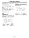
1
Installer manual NIBE™ F2030 LEK Air/water heat pump IHB GB 13-1 231115 Table of Contents 1 Important information Safety information 2 2 2 Delivery and handling 7 Transport and storage Assembly Supplied components Removing the side cover 7 7 10 11 3 The heat pump design 12 General Electrical panel 4 Pipe connections General Pipe coupling heating medium circuit Pressure drop, heating medium side 12 14 15 8 Control - Channels 33 15 15 15 General Connections Optional connections Connecting accessories 17 19 22 23 NIBE™ F2030 28 28 28 29 30 17 Preparations Filling and venting the heating medium system Balance temperature Stop temperature Soft-starter 7 Control - Introduction 24 24 24 26 26 27 General Navigation Display explanation Control conditions 5 Electrical connections 6 Commissioning and adjusting Compressor heater Collar heater Phase sequence control Start-up and inspection Readjusting, heating medium side Adjustment, charge flow 24 24 24 24 24 24 Status channels Temperature channels Setting channels 33 33 34 9 Disturbances in comfort 35 Troubleshooting 35 10 Accessories 39 11 Technical data 41 Dimensions and setting-out coordinates Sound pressure levels Technical specifications Electrical circuit diagram 41 42 43 46 Item register 50 Table of Contents | 1 1 Important information Safety information ory for most products sold in the EU, regardless where they are made. This manual describes installation and service procedures for implementation by specialists. This appliance is designed for use in a home environment and not intended to be used by persons (including children) with reduced physical, sensory or mental capabilities, or lack of experience and knowledge, unless they have been given supervision or instruction concerning use of the appliance by a person responsible for their safety. This in accordance to applicable parts of the low-voltage directive 2006/95/EC, LVD. The appliance is also intended for use by experts or trained users in shops, hotels, light industry, on farms and in similar environments. This in accordance to applicable parts of the machinery directive 2006/42/EC. Children should be supervised to ensure that they do not play with the appliance. This is an original instruction manual. Translation is not allowed without approval from NIBE. Rights to make any design or technical modifications are reserved. ©NIBE 2013. Symbols NOTE This symbol indicates danger to machine or person. Caution This symbol indicates important information about what you should observe when maintaining your installation. TIP This symbol indicates tips on how to facilitate using the product. Marking The CE marking means that NIBE ensures that the product meets all regulations that are placed on it based on relevant EU directives. The CE mark is obligat2 Chapter 1 | Important information NIBE™ F2030 Safety precautions If the switch does not have sufficient breaking capacity, malfunctions and fire can occur. Caution Always use a fuse with the correct rating in the locations where fuses are to be used. Connecting the unit with copper wire or other metal thread can cause unit breakdown and fire. Install the system in full accordance with this installation manual. Incorrect installation can cause bursts, personal injury, water leaks, refrigerant leaks, electric shocks and fire. Observe the measurement values before working on the cooling system, especially when installing in small rooms, so that the limit for the refrigerant's density is not exceeded. Consult an expert to interpret the measurement values. If the refrigerant density exceeds the limit, lack of oxygen can occur in the event of any leak, which can cause serious accidents. Use original accessories and the stated components for the installation. If parts other than those stated by us are used, water leaks, electric shocks, fire and personal injury may occur as the unit may not work properly. Ventilate the working area well – refrigerant leakage may occur during service work. If the refrigerant comes into contact with naked flames, poisonous gas is created. Install the unit in a location with good support. Unsuitable installation locations can cause the unit to fall and cause material damage and personal injury. Installation without sufficient support can also cause vibrations and noise. Ensure that the unit is stable when installed, so that it can withstand earthquakes and strong winds. Unsuitable installation locations can cause the unit to fall and cause material damage and personal injury. The electrical installation must be carried out by a qualified electrician and the system must be connected as a separate circuit. Power supply with insufficient capacity and incorrect function can cause electric shocks and fire. Use the stated cables for the electrical connection, tighten the cables securely in the terminal blocks and relieve the wiring correctly to prevent overloading the terminal blocks. Loose connections or cable mountings can cause abnormal heat production or fire. Check, after completed installation or service, that no refrigerant leaks from the system in gas form. If refrigerant gas leaks into the house and comes into contact with an aerotemp, an oven or other hot surface, poisonous gases are produced. Switch off the compressor before opening/breaching the refrigerant circuit. If the refrigerant circuit is breached /opened whilst the compressor is running, air can enter the process circuit. This can cause unusually high pressure in the process circuit, which can cause bursts and personal injury. Switch off the power supply in the event of a service or inspection. If the power supply is not shut off, there is a risk of electric shocks and damage due to the rotating fan. Do not run the unit with removed panels or protection. Touching rotating equipment, hot surfaces or high voltage parts can cause personal injury due to entrapment, burns or electric shocks. Cut the power before starting electrical work. Failure to cut the power can cause electric shocks, damage and incorrect function of the equipment. Cables must be routed so that they are not damaged by metal edges or trapped by panels. Incorrect installation can cause electric shocks, heat generation and fire. Do not install the unit in close proximity to locations where leakage of combustible gases can occur. If leaking gases collect around the unit, fire may occur. Do not install the unit where corrosive gas (for example nitrous fumes) or combustible gas or steam (for example thinner and petroleum gases) can build up or collect, or where volatile combustible substances are handled. Corrosive gas can cause corrosion to the heat exchanger, breaks in plastic parts etc. and combustible gas or steam can cause fire. Do not use the unit where water splashes may occur, for example in laundries. The indoor section is not waterproof and electric shocks and fire can therefore occur. Do not use the unit for specialist purposes such as for storing food, cooling precision instruments, freeze-conservation of animals, plants or art. This can damage the items. Do not install and use the system close to equipment that generates electromagnetic fields or high frequency harmonics. Equipment such as inverters, standby sets, medical high frequency equipment and telecommunications equipment can affect the unit and cause malfunctions and breakdowns. The unit can also affect medical equipment and telecommunications equipment, so that it functions incorrectly or not at all. Do not install the outdoor unit in the locations stated below. - Locations where leakage of combustible gas can occur. - Locations where carbon fibre, metal powder or other powder that can enter the air. - Locations where substances that can affect the unit, for example, sulphide gas, chlorine, acid or alkaline substances can occur. - Locations with direct exposure to oil mist or steam. - Vehicles and ships. - Locations where machines that generate high frequency harmonics are used. - Locations where cosmetic or special sprays are often used. - Locations that can be subjected to direct salty atmospheres. In this case, the outdoor unit must be protected against direct intakes of salty air. - Locations where large amounts of snow occur. - Locations where the system is exposed to chimney smoke. If the bottom frame of the outdoor section is corroded, or in any other way damaged, due to long periods of operation, it must not be used. Using an old and damaged frame can cause the unit to fall and cause personal injury. If soldering near the unit, ensure that solder residue does not damage the drip tray. If solder residue enters the unit during soldering, small holes can appear in the tray resulting in water leakage. To prevent damage, keep the indoor unit in its packing or cover it. Care Do not allow the drainage pipe to exit into channels where poisonous gases, containing sulphides for example, can occur. If the pipe exits into such a channel, any poisonous gases will flow into the room and seriously affect the user's health and safety. Carry out the electrical installation with care. Do not connect the ground lead to the gas line, water line, lightning conductor or telephone line's ground lead. Incorrect grounding can cause unit faults such as electric shocks due to short-circuiting. Insulate the unit's connection pipes so that the ambient air moisture does not condense on them. Insufficient insulation can cause condensation, which can lead to moisture damage on the roof, floor, furniture and valuable personal property. Use main switch with sufficient breaking capacity. Do not install the outdoor unit in a location where insects and small animals can inhabit. NIBE™ F2030 Chapter 1 | Important information 3 Insects and small animals can enter the electronic parts and cause damage and fire. Instruct the user to keep the surrounding equipment clean. Take care when carrying the unit by hand. If the unit weights more than 20 kg, it must be carried by two people. Use gloves to minimize the risk of cuts. Dispose of any packaging material correctly. Any remaining packaging material can cause personal injury as it may contain nails and wood. Serial number The serial number can be found at the top left of the rear cover and on the foot of the product. 6HULDO QXPEHU Do not touch any buttons with wet hands. This can cause electric shocks. Do not touch any refrigerant pipes with your hands when the system is in operation. During operation the pipes become extremely hot or extremely cold, depending on the method of operation. This can cause burn injuries or frost injuries. Do not shut off the power supply immediately after operation has start. Wait at least 5 minutes, otherwise there is a risk of water leakage or breakdown. Do not control the system with the main switch. This can cause fire or water leakage. In addition, the fan can start unexpectedly, which can cause personal injury. Especially for units intended for R407C - Do not use other refrigerants that those intended for the unit. Caution - Do not use charging bottles. These types of bottles change the composition of the refrigerant, which makes the performance of the system worse. Always give the product's serial number when reporting a fault. - When filling refrigerant, the refrigerant must always leave the bottle in liquid form. Country specific information Installer manual This installer manual must be left with the customer. 4 Chapter 1 | Important information NIBE™ F2030 Inspection of the installation Current regulations require the heating installation to be inspected before it is commissioned. The inspection must be carried out by a suitably qualified person. Fill in the page for information about installation data in the User manual. ✔ Description Notes Signature Date System flushed System vented Particle filter Shut-off and drain valve Charge flow set Fuses property Safety breaker Earth circuit-breaker Heating cable type/effect Fuse size, heating cable (F3) Communication cable connected Miscellaneous Condensation water pipe Insulation condensation water pipe, thickness (if KVR 10 is not used) NIBE™ F2030 Chapter 1 | Important information 5 Contact information AT KNV Energietechnik GmbH, Gahberggasse 11, 4861 Schörfling Tel: +43 (0)7662 8963-0 Fax: +43 (0)7662 8963-44 E-mail: mail@knv.at www.knv.at CH NIBE Wärmetechnik AG, Winterthurerstrasse 710, CH-8247 Flurlingen Tel: (52) 647 00 30 Fax: (52) 647 00 31 E-mail: info@nibe.ch www.nibe.ch CZ Druzstevni zavody Drazice s.r.o, Drazice 69, CZ - 294 71 Benatky nad Jizerou Tel: +420 326 373 801 Fax: +420 326 373 803 E-mail: nibe@nibe.cz www.nibe.cz DE NIBE Systemtechnik GmbH, Am Reiherpfahl 3, 29223 Celle Tel: 05141/7546-0 Fax: 05141/7546-99 E-mail: info@nibe.de www.nibe.de DK Vølund Varmeteknik A/S, Member of the Nibe Group, Brogårdsvej 7, 6920 Videbæk Tel: 97 17 20 33 Fax: 97 17 29 33 E-mail: info@volundvt.dk www.volundvt.dk FI NIBE Energy Systems OY, Juurakkotie 3, 01510 Vantaa Puh: 09-274 697 0 Fax: 09-274 697 40 E-mail: info@nibe.fi www.nibe.fi FR AIT France, 10 rue des Moines, 67000 Haguenau Tel : 03 88 06 24 10 Fax : 03 88 06 90 15 E-mail: info@nibe.fr www.nibe.fr GB NIBE Energy Systems Ltd, 3C Broom Business Park, Bridge Way, Chesterfield S41 9QG Tel: 0845 095 1200 Fax: 0845 095 1201 E-mail: info@nibe.co.uk www.nibe.co.uk NL NIBE Energietechniek B.V., Postbus 2, NL-4797 ZG WILLEMSTAD (NB) Tel: 0168 477722 Fax: 0168 476998 E-mail: info@nibenl.nl www.nibenl.nl NO ABK AS, Brobekkveien 80, 0582 Oslo, Postadresse: Postboks 64 Vollebekk, 0516 Oslo Tel. sentralbord: +47 23 17 05 20 E-mail: post@abkklima.no www.nibeenergysystems.no PL NIBE-BIAWAR Sp. z o. o. Aleja Jana Pawła II 57, 15-703 BIAŁYSTOK Tel: 085 662 84 90 Fax: 085 662 84 14 E-mail: sekretariat@biawar.com.pl www.biawar.com.pl RU © "EVAN" 17, per. Boynovskiy, Nizhny Novgorod Tel./fax +7 831 419 57 06 E-mail: info@evan.ru www.nibe-evan.ru SE NIBE AB Sweden, Box 14, Hannabadsvägen 5, SE-285 21 Markaryd Tel: +46-(0)433-73 000 Fax: +46-(0)433-73 190 E-mail: info@nibe.se www.nibe.se For countries not mention in this list, please contact Nibe Sweden or check www.nibe.eu for more information. 6 Chapter 1 | Important information NIBE™ F2030 2 Delivery and handling Transport and storage F2030 must be transported and stored vertically. NOTE Ensure that the heat pump cannot fall over during transport. Assembly ႑ Place F2030 outdoors on a solid level base that can take the weight, preferably a concrete foundation. If concrete slabs are used they must rest on asphalt or shingle. ႑ The concrete foundation or slabs must be positioned so that the lower edge of the evaporator is at the level of the average local snow depth, although a minimum of 300 mm. ႑ The F2030 should not be positioned next to sensitive walls, for example, next to a bedroom. ႑ Also ensure that the placement does not inconvenience the neighbours. ႑ F2030 must not be placed so that recirculation of the outdoor air can occur. This causes lower output and impaired efficiency. ႑ The evaporator should be sheltered from direct wind. Place F2030 protected from wind against the evaporator. ႑ Large amounts of condensation water as well as melt water from defrosting can be produced. Condensation water must be led off to a drain or similar (see page 8). ႑ Care must be exercised so that the heat pump is not scratched during installation. If there is a risk of snow slip from roof, a protective roof or cover must be erected to protect the heat pump, pipes and wiring. PLQ PP LEK LEK Do not place F2030 directly on the lawn or other non solid surface. NIBE™ F2030 Chapter 2 | Delivery and handling 7 Lift from the street to the set up location Condensation water trough If the base allows, the simplest thing is to use a pallet truck to move the F2030 to the set up location. The condensation water trough is used to collect and lead away condensation water from the heat pump. NOTE NOTE The centre of gravity is offset to one side (see print on the packaging). It is important to the heat pump function that condensation water is led away and that the drain for the condensation water run off is not positioned so that it can cause damage to the house. NOTE Pipe with heating cable for draining the condensation water trough is not included. NOTE To ensure this function the accessory KVR 10 should be used. LEK NOTE The electrical installation and wiring must be carried out under the supervision of an authorised electrician. If F2030 must be transported across soft ground, for example a lawn, we recommend that a crane that can lift it to the set up location is used. When the F2030 is lifted by crane the packaging must be untouched and the load equally distributed with a boom, as illustrated above. Caution If none of the recommended alternatives is used good lead off of condensation water must be assured. ႑ The condensation water (up to 50 litres/day) collected in the trough should be routed by pipe to an appropriate drain, it is recommended that the shortest outdoor stretch possible is used. ႑ The section of the pipe that can be affected by frost must be heated by the heating cable to prevent freezing. ႑ Route the pipe downward from F2030. ႑ The outlet of the condensation water pipe must be at a depth that is frost free or alternatively indoors (with reservation for local ordinances and regulations). It is not permitted to lift anything other than the machine feet. ႑ Use a water trap for installations where air circulation may occur in the condensation water pipe. Scrapping ႑ The insulation must be tight against the bottom of the condensation water trough. If a crane cannot be used F2030 can be transported using an extended sack truck. F2030 must be used on the side marked "heavy side" and two people are required to get the F2030 up. Lift from the pallet to final positioning Before lifting remove the packaging and the securing strap to the pallet. Place lifting straps around each machine foot. Lifting from the pallet to the base requires four persons, one for each lifting strap. When scrapping, the product is removed in reverse order. Lift by the bottom panel instead of a pallet! 8 Chapter 2 | Delivery and handling NIBE™ F2030 Recommended alternatives Gutter drainage Stone caisson )URVW SURRI Frostfritt d GHSWK LEK/APH :DWHU VHDO LEK/APH If the house has a cellar the stone caisson must be positioned so that condensation water does not affect the house. Otherwise the stone caisson can be positioned directly under the heat pump. Frostfritt )URVWdjup SURRI GHSWK The outlet of the condensation water pipe must be at frost free depth. Route the pipe downward from F2030. The condensation water pipe must have a water seal to prevent air circulation in the pipe. The outlet of the condensation water pipe must be at frost free depth. Drain indoors -RLQW Skarv :DWHU VHDO Vattenlås LEK/APH The condensation water is lead to an indoor drain (subject to local rules and regulations). Route the pipe downward from F2030. The condensation water pipe must have a water seal to prevent air circulation in the pipe. NIBE™ F2030 Chapter 2 | Delivery and handling 9 Installation area 400 mm The distance between F2030 and the house wall must be at least 350 mm. Clearance above the F2030 should be at least one metre. VSDFH EHKLQG PP )UHH Fritt utrymme bakom PP 600mm PP 400 mm 600PP mm 0LQLPXP IUHH VSDFH fritt utrymme 3000 mm 0LQLPXP IUHHMinimalt VSDFH PP Fritt utrymme framför )UHH VSDFH LQ IURQW Min. avståndGLVWDQFH 0LQLPXP vid användning RI flera VHYHUDO ) av F2030 GXULQJ XVH Minimalt fritt utrymme Supplied components LEK 2 flexible hoses (R25) with 4 seals Particle filterR25 10 Chapter 2 | Delivery and handling NIBE™ F2030 LEK / APH Removing the side cover NIBE™ F2030 Chapter 2 | Delivery and handling 11 3 The heat pump design General 41 8% (% $$ %3 %7 *4 (3 (% 50 ;/ $$ ;/ 41 41 LEK 41 %7 *4 +6 :0 %7 %3 %3 ;/ 41 (% 8% %7 3) 3) (3 %7 ;/ %7 APH ;/ 3) %7 12 Chapter 3 | The heat pump design ;/ NIBE™ F2030 Pipe connections XL1 Connection, heating medium out from F2030, G1 (Ø28 mm) XL2 Connection, heating medium in to F2030, G1 (Ø28 mm) XL20 Service connection, high pressure XL21 Service connection, low pressure XL40 Connection, drip tray drain (Ø40 mm) Sensors etc. BP1 High pressure switch (29 bar) BP2 Low pressure pressostat BP10 High pressure switch (32 bar) BT3 Temperature sensor, return BT12 Temperature sensor, condenser supply line BT14 Temperature sensor, hot gas BT15 Temperature sensor, fluid pipe BT16 Temperature sensor, evaporator BT17 Temperature sensor, suction gas BT28 Temperature sensor, ambient Electrical components AA100 Joint card, sensor AA101 Joint card EB10 Compressor heater EB11 Drip tray heater EB13 Collar heater GQ1 Fan Cooling components EP1 Evaporator EP2 Condenser GQ10 Compressor HS1 Drying filter QN1 Expansion valve QN2 4-way valve QN30 Solenoid valve, liquid injection QN31 Solenoid valve, subcooling QN34 Expansion valve, subcooling RM1 Non-return valve Miscellaneous PF1 Type plate PF3 Serial number UB1 Cable gland, incoming supply WM5 Condensation water trough Designations in component locations according to standard IEC 81346-1 and 81346-2. NIBE™ F2030 Chapter 3 | The heat pump design 13 Electrical panel $$ $$ $$6) )& %$ )% 4$ ; ) ; ; $$ ; $$6 $$6 $$6 $$6 $$ Electrical components AA6 Relay card with power supply unit AA10 Soft-start relay AA21 Control card with display S1 Plus button S2 Minus button S3 Enter button S4 Reset button SF3 Display contrast AA102 BA1 F3 FB1 FC2 QA51 X1 X3 X4 X5 Fan control board Phase sequence monitor (3-phase) Fuse for external heating cable (250 mA) Automatic protection (10 A/30 mA) Motor fuse Contactor, main contactor Terminal block, incoming supply Terminal block, charge pump, external heater Terminal block, common alarm Terminal block, thermostat, compressor blocking and communication indoor module. Designations in component locations according to standard IEC 81346-1 and 81346-2. 14 Chapter 3 | The heat pump design NIBE™ F2030 4 Pipe connections General Pipe installation must be carried out in accordance with current norms and directives. F2030 can only operate up to a return temperature of about 55 °C and an outgoing temperature of about 65 °C from the heat pump. F2030 is not equipped with external shut off valves on the water side; these must be installed to facilitate any future servicing. The return temperature is limited by the return line sensor. pump is connected to an intermediate circuit with a heat exchanger, pump and water with anti-freeze. (Does not apply when docking to NIBE indoor module.) Pressure drop, heating medium side F2030 -7, 9 3UHVVXUH GURS N3D y 45 F2030-9 kW 40 F2030-7 kW 35 Water volumes When docking with F2030 a minimum available system volume of at least 20 litres per kW output on the heat pump is recommended. 30 25 20 15 10 NOTE 5 0 The pipe work must be flushed before the heat pump is connected, so that any contaminants do not damage the components parts. Pipe coupling heating medium circuit ႑ F2030 can be connected to the heating system according to one of the system solutions that can be downloaded from the website www.nibe.eu. ႑ The heat pump must be vented by the upper connection (XL1) using the venting nipple on the enclosed flexible hose. ႑ The supplied particle filter must be installed before the inlet, i.e. the lower connection XL2) on F2030. ႑ All outdoor pipes must be thermally insulated with at least 19mm thick pipe insulation. ႑ Install shutoff and drain valves so that F2030 can be emptied in the event of prolonged power failures. ႑ The supplied flexible hoses act as vibration dampers. The flexible pipes are fitted so an elbow is created, thus acting as vibration damping. 0 500 1000 1500 2000 2500 3000 3500 )ORZ OLWUHVHFRQG +HDW LQVXODWLRQ L Charge pump NOTE The charge pump must be operational, even if F2030 is not running, to prevent damage due to freezing. The charge pump can also be controlled directly from F2030, terminal block (X3), which takes the ambient temperature into consideration. Alternatively, the heat NIBE™ F2030 Chapter 4 | Pipe connections 15 LEK ;/ 16 ;/ Chapter 4 | Pipe connections NIBE™ F2030 5 Electrical connections General ႑ A heat pump must not be connected without the permission of the electricity supplier and must be connected under the supervision of a qualified electrician. ႑ If a miniature circuit breaker is used this should have motor characteristic "C" (compressor operation). For MCB size see "Technical Specifications". ႑ F2030 does not include an omnipolar circuit breaker on the incoming power supply. The heat pump’s supply cable must be connected to a circuitbreaker with at least a 3 mm breaking gap. When the building is equipped with an earth-fault breaker the heat pump should be equipped with a separate one. Incoming supply must be 400 V 3NAC 50Hz via distribution boards with fuses. ႑ If an insulation test is to be carried out in the building, disconnect the heat pump. ႑ Connect control signal cable for thermostat to terminal (X5). Cable type: unscreened LiYY, screened LiYCY. Cable area, at least 0.22with cable lengths less than 50m. ႑ ႑ The routing of cables for heavy current and signals should be made out through the cable glands on the heat pump's right-hand side, seen from the front. ႑ Charge pump for F2030 can be connected to separate supply or to terminal block (X3). NOTE! If F2030 is not powered and the charge pump is connected to the terminal block (X3) there is a risk of freezing ႑ A common alarm can be connected to terminal (X4). NOTE Electrical installation and service must be carried out under the supervision of a qualified electrician. Electrical installation and wiring must be carried out in accordance with the stipulations in force. NOTE The live external control must be taken into consideration when connecting. Alternatively the relevant screened signal cable is connected from terminal (X5) to indoor module from NIBE. $$ $$ $$6) )& %$ )% 4$ ; ) ; ; $$ ; $$6 $$6 $$6 $$6 $$ NIBE™ F2030 Chapter 5 | Electrical connections 17 Accessibility, electrical connection Removing the side cover LEK / APH Unscrew the screws and lift off the cover. 18 Chapter 5 | Electrical connections NIBE™ F2030 Connections NOTE To prevent interference, unscreened communication and/or sensor to external connections cables must not be laid closer than 20 cm to high voltage cable when cable routing. Power connection APH &RQQHFWLRQ LEK ,QFRPLQJ VXSSO\ Incoming supply cable is supplied and factory connected to the terminal block -X1. Approx. 1.8 m cable is accessible outside the heat pump. On installation the unions must be mounted on the rear of the heat pump. NIBE™ F2030 Chapter 5 | Electrical connections 19 Connecting external control voltage NOTE Mark up any junction boxes with warnings for external voltage. When connecting external control voltage with separate earth-fault breaker, remove the straps between terminal blocks X1:L1 and X1:L and between terminal blocks X1:N andX1:0 (see image). Control voltage (230V 50 Hz) is connected to terminal blocks X1:L and X1:0 (as illustrated). ) F2030 ([WHUQDO Externt -X1 Charge pump To let F2030 control the charge pump (GP12), connect it to the terminal block X3:1(PE), 3(L) and 4(N). Pump activity is dependent on the status of F2030, heating/hot water requirement and the ambient temperature. Pump exercising is handled by F2030. With potential free connection of the circulation pump you replace the bracket with separate voltage supply for X3:2(L). Anti-freeze function At temperatures below +2 °C the charger pump runs periodically, to prevent the water from freezing in the charge circuit. The function also protects against excess temperatures in the charge circuit. This function applies on the condition that F2030 is powered. NOTE 0 0 L L There is a risk of freezing when the charge pump is connected to the terminal block - X3 and F2030 is not powered. N L3 ) ([WHUQDO 7 L2 6 L1 5 4 3 ; 2 N L PE 1 ; *3 At connection of external control voltage you must connect a switch (for tariff control) to connection X5:5 and X5:6 (compressor blocking) to prevent MP alarm. ) ([WHUQDO 8 7 6 &RPSUHVVRU EORFNLQJ 5 4 3 2 1 ; 20 Chapter 5 | Electrical connections NIBE™ F2030 External heating cable (KVR 10) Cable routing F2030 is equipped with a plinth for external heating cable EB14, not supplied). The connection is fused with 250 mA (F3, 15 W/m). If another cable is to be used the fuse must be replaced with a suitable one. The following image displays the recommended cable routing from the junction box to the condensation water trough on the outside of F2030. The transfer from electrical cable to heating cable must occur after the lead-in to the condensation water trough. The distance between the junction box and the lead-in to the condensation water trough is approx.1600 mm. Length (m) Total output (W) Fuse (F3) NIBE Part no. 1 3 6 15 45 90 T100mA/250V T250mA/250V T500mA/250V 718085 518900* 718086 * Fitted at the factory. Connect external heating cable (EB14) to terminal block X3:4 and 7. If there is a ground cable connect it to X3:1. See following image: ) ([WHUQDO 7 6 ([WHUQDO KHDW FDEOH 5 4 3 (% 2 1 5RXWLQJ QRQ KHDW FRQGXFWLQJ SDUWV RI WKH KHDWLQJ FDEOH /HDG LQ ; ) +HDWLQJ FDEOH NOTE The pipe must be able to withstand the heat from the heating cable. To ensure this function the accessory KVR 10 should be used. NIBE™ F2030 Chapter 5 | Electrical connections 21 Optional connections NOTE The following pages about thermostats, additional heat, common alarms and downtime, do not apply when F2030 is controlled by a NIBE indoor module. If the ambient temperature exceeds 40 °C compressor operation is blocked and the downtime relay is activated. The connection to the additional relay is made as illustrated below. ([WHUQDO $GGLWLRQDO KHDW Tillsatsvärme Thermostat control 'RZQWLPH You can use a basic thermostat or a closing potentialfree contact to switch the compressor on and off. This thermostat should be of the breaking type (NC) when the set temperature has been reached. The contactor should be potential free. Connect the thermostat to terminal block X5:7 and 8 as illustrated below. ) ([WHUQDO 8 7 7KHUPRVWDW ) NO Stillestånd NO NC $$- NC COM C NO NO NC NC COM C $$- Max load across the relay contactors is 250V 2A. During operations without the need of the additional heat or downtime the relay contactors are closed between COM and NO. Additional heat and downtime are acquired between COM and NC. The contactors are drawn in the deenergized state. 6 5 4 3 2 Additional and downtime relays are activated during normal operating conditions for F2030. Both relays are deactivated in the event of operating disruptions. 1 ; Example of addition connection Basic electrical circuit diagram for connection of auxiliary relays for additional heat and downtime. Additional heat / Downtime F2030 is equipped with a potential free contactor intended for additional heat. Max 250V 2A. The setting of the ambient temperature (balance temperature) when the additional relay is activated is made on channel A5, see the section "Control - Channel description". NO NC &20 O/C 12 – 230V External additional heat is connected via the additional relay terminal block J5:C,NO and NC on control card AA21. Conditions for connecting additional heat: ႑ the ambient temperature should be lower than the set balance temperature (channel A5). ႑ The compressor must have been operating for the minimum period that can be set in channel A6. Defrosting is included in this time. $X[LOLDU\ FRQWDFWRU Hjälpkontaktor QRW VXSSOLHG If the ambient temperature falls to a level below the set value, stop temperature (downtime), in channel A7 compressor operations are blocked and all heating must take place using the external additional heat via the downtime relay, terminal block J6:C,NO and NC on control card AA21. This function is also activated when F2030 is de-energized. 22 Chapter 5 | Electrical connections NIBE™ F2030 Communication F2030 can communicate with NIBE indoor modules, by connecting the indoor module to the terminal block X5:1-3 according to the following image: F2030 ) Innemodul ,QGRRU PRGXOH -X5; 8 7 6 5 4 3 GND 2 B- 1 A+ For connection of indoor module, see relevant manual on www.nibe.eu. External indication of main alarm F2030 is equipped with a contact for external indication of common alarms. The function becomes active with all types of existing alarms. Max load on the relay contact is250V 2A. The connection for external indication of common alarms is made to terminal block X4:1 to 3 as illustrated below: ) ([WHUQDO 3 NC 2 NO 1 COM Summalarm &RPPRQ DODUP ; Connecting accessories Instructions for connecting accessories are in the installation instructions provided for the respective accessory. See page 39 for the list of the accessories that can be used with F2030. NIBE™ F2030 Chapter 5 | Electrical connections 23 6 Commissioning and adjusting Preparations Soft-starter ႑ Ensure that the heat pump cannot be damaged during transport. F2030 is equipped with a soft-start (AA10) that limits the inrush current for the compressor. ႑ Before commissioning, check that the heating circuit is filled and well vented. Compressor heater ႑ Check the pipe system for leaks. Filling and venting the heating medium system F2030 is equipped with a compressor heater that heats the compressor before start-up and when the compressor is cold. NOTE 1. The heating medium system is filled with water to The compressor heater must have been connected for 6 – 8 hours before the first start, see the section "Start-up and inspection". the required pressure. 2. Vent the system using the venting nipple on the enclosed flexible pipe and possibly the circulation pump. 40 Collar heater F2030 is equipped with a collar heater that can heat the fan collar if necessary (not activated upon delivery). NOTE The collar heater is only required in certain cases where the ambient temperature is too low for a long period. Phase sequence control %$ Balance temperature The balance temperature is the outdoor temperature when the heat pump’s stated output is equal to the building’s output requirement. This means that the heat pump covers the whole building’s output requirement down to this temperature. Set the balance temperature, additional heat, in channel A5. Stop temperature When the stop temperature (channel A7) is set between -10 and -25 C the flow temperature is limited linearly from -10 C / 65 °C to -25 °C / 63 °C (see diagram on page 45). If the ambient temperature is below the set value for stop temperature heating must occur using the additional heat. 24 Chapter 6 | Commissioning and adjusting The phase sequence sensor (BA1) starts as soon as the power supply is connected to the heat pump. Check the phase sequence as shown below. ႑ Red LED is lit at correct phase sequence ႑ If there is a fault in the phase sequence, the heat pump receives an alarm 07 in channel S1 and the LED flashes. NIBE™ F2030 NOTE Check the phase sequence when starting! NIBE™ F2030 Chapter 6 | Commissioning and adjusting 25 8. The communication cable or external thermostat Start-up and inspection is connected after 6 – 8 hours. See section Thermostat control” electrical connection chapter. 1. Communication cable, terminal block (X5:1-3) or thermostat, terminal block (X5:7-8) must not be connected. 9. Restart any NIBE SMO or NIBE indoor module. See information in relevant manual on www.nibe.eu 2. Turn the isolator switch on. 3. Ensure that the F2030 is connected to the power 10. Once the connection is made, the compressor starts after approx. 180 minutes if needed. source. 11. Adjust the charge flow according to the diagram, 4. Check that the motor circuit-breaker (FC2) is on. 5. Check that the LED on phase sequence sensor (BA1) see the section "Adjustment, charge flow" 12. 13. 14. 15. lights red. 6. The compressor heater (EB10) must have been operational for at least 6 – 8 hours before the compressor start can be initiated. This is done by switching on the control voltage and disconnecting the communications cable or thermostat. Adjust the menu settings if necessary. Fill in the commissioning report in the user manual. Reinstall the removed panels and cover. Remove the protective film from the cover on F2030. NOTE 7. The display on the control card (AA21) shows The external control must be taken into consideration when connecting. C0/CC F0 H1/H3 depending on the ambient temperature. During this period the compressor is heated to increase the service life. $$ $$ $$6) )& %$ )% 4$ ; ) ; ; $$ ; $$6 $$6 $$6 $$6 $$ Readjusting, heating medium side the system is stable (correct pressure and all air eliminated) the automatic heating control system can be set as required. Air is initially released from the hot water and venting may be necessary. If bubbling sounds can be heard from the heat pump, the circulation pump and radiators the entire system will require further venting. When 26 Chapter 6 | Commissioning and adjusting NIBE™ F2030 The diagrams show the heat pump with a high fan Adjustment, charge flow speed, at low fan speeds ΔT will be 0.5 to 1 degrees lower. Adjusting the temperature difference (ΔT) between the flow temperature and the return temperature is best done during hot water charging or at high load. Quoted outputs refer to compressor, fan and control at nominal heating medium flow. During operation that requires defrosting the relationship between input and output is reduced by about 10%. This is most easily done using the temperatures measured in channel T2 (supply temperature) minus channel T3 (return temperature). This temperature difference (ΔT) is adjusted using the circulation pump and control valve. Adjustment is performed with stable operation about 5 minutes after start, or about 5 minutes after defrosting at cold ambient temperatures. The temperature difference shall be as in the diagram below (+1- 2 K). At outdoor temperatures above 28 °C the charge flow can be increased by 30 % to obtain a lower ΔT. Charge flow and Phase current Charge flow F2030-7/F2030-9 Adjustment of charge flow dT (K) 16 Max Nominal Min 14 12 10 8 6 4 2 0 -25 -20 -15 -10 -5 0 5 10 15 20 25 30 35 40 Outside temperature (°C) F2030-7 F2030-9 Phase current, A Specified power, kW Phase current, A Specified power, kW 12 16 10 p W55 W45 W35 Rated output 14 W35 W45 W55 Rated output 12 W55 W45 W35 8 y W55 W45 W35 10 6 8 4 W55 W45 W35 2 W55 W45 W35 -20 -15 -10 -5 0 5 10 15 W55 W45 W35 4 W55 W45 W35 Phase current Phase current 0 -25 6 2 20 25 30 35 40 Outside temperature (°C) 0 -25 -20 -15 -10 -5 0 5 10 15 20 25 30 35 40 Outside temperature (°C) NIBE™ F2030 Chapter 6 | Commissioning and adjusting 27 7 Control - Introduction General Navigation F2030 is equipped with an internal electronic control that handles those functions that are necessary for operation of the heat pump, for example defrosting, stop at max/min temperature, connection of the compressor heater as well as enabling the heater for the condensation watering trough and monitoring of pressure switches. The temperatures, number of starts and the operating time can also be read. 34 The integrated controller is set during installation and can be used during a service. Under normal operating conditions the home owner does not need to have access to the controller. F2030 has an integrated return line sensor that limits the return temperature. F2030 can also be switched on/off via signals from other control equipment or a thermostat. If F2030 is controlled from a NIBE indoor module (accessory) the control is described in the instructions supplied. The indoor module communicates with NIBE SMO or F2030 which means that settings and measurement values from F2030 can be adjusted and read in the indoor module. Plus button The plus button (S1) is used to browse through the channel system (forwards) or raise the value of the selected parameter. See the section “Control” – “Channel description” Minus button The minus button (S2) is used to browse through the channel system (backwards) or lower the value of the selected parameter. See the section “Control” – “Channel description” Enter button The Enter button (S3) is used to activate and confirm value changes. See the section “Control” – “Channel description” To modify a value, first press the Enter button to activate modification mode, the value flashes. Adjust the value as required using the Plus button or Minus button. Holding the Plus button or Minus button in for about 3 seconds speeds up the change in value. Then confirm using the Enter button. The value will stop flashing. The instructions are divided into three parts: status, temperatures and adjustable values. Quick movement between the different types is carried out by pressing the enter button when STATUS, TEMP. or ADJUST. are displayed. 28 Chapter 7 | Control - Introduction NIBE™ F2030 Display explanation C0 F0 S1 Heater: H The compressor heater is always active when the compressor is switched off. H0 The condensation water trough heater is connected during defrosting when the ambient temperature falls below or is equal to 2.5 °C. 01 Compressor: C Shows the present compressor status. C0 Compressor off, circulation pump off C Flashes when the compressor wants to start but is prevented by the time conditions or high return temperature. C1 Compressor on, circulation pump on CC Compressor off, circulation pump on CD Defrosting in progress If the collar heater is permitted (channel A14), it activates every third defrosting, when the ambient temperature lies below 2 °C. H0 Compressor heater off Condensation water trough heater off Collar heater off H1 Compressor heater on H2 Condensation water trough heater on H3 Compressor heater on Condensation water trough heater on Fan: F H4 Collar heater on The fan has two speeds, high or low. The fan is controlled by the ambient temperature. The lower speed is used when the ambient temperature is too high to limit the output. The fan does not run during defrosting. At an ambient temperature lower than the temperature in the table below the fan speed is changed to high. H5 Compressor heater on Type Ambient temperature (°C) 7 kW 20 9 kW 20 Collar heater on H6 Condensation water trough heater on Collar heater on H7 Compressor heater on Condensation water trough heater on Collar heater on F0 Fan off F1 Fan on, low speed F2 Fan on, high speed NIBE™ F2030 Channel: S1 Shows the current channel. Change channels using the Plus button or the Minus button. Value: 01 Shows the current value. Increase/decrease value using the plus button respective minus button. Chapter 7 | Control - Introduction 29 Control conditions B = Set temperature for cold outdoor air (channel A7). Control conditions, cold outdoor air 1. The ambient temperature (channel T1) drops below A = Set temperature for cold outdoor air + 2.1 °C. ႑ ႑ ႑ ႑ ႑ the set temperature in channel A7 (B). The heat pump stops and both the relays are activated. When the ambient air temperature (channel T1) drops below the set temperature in channel A7 the heat pump stops and indicates 03 in channel S1. Both the additional relay and the downtime relay are then activated at the same time. 2. The ambient temperature is 2.1 °C) above the set temperature in channel A7 (A). A time counter starts from 0. If the ambient temperature sensor registers a temperature that is at least 2.1 °C higher than the set temperature in channel A7, a time counter starts. 3. The ambient temperature falls below A. The timer is reset and stopped. 4. The ambient temperature returns to above A. The When the time counter has reached 45 minutes, both the additional relay and downtime relay deactivate to obtain a more comfortable temperature for the compressor to start at. time counter starts again (from 0). 5. The time counter has counted to 45 minutes. Both relays are deactivated. 6. The time counter has counted to 60 minutes. The When a further 15 minutes have passed, the compressor is permitted to start and the additional relay activates a few seconds later. However, the downtime relay is deactivated. compressor is permitted to start again. NOTE It is heat pump’s ambient temperature sensor that applies. If the ambient temperature at any point during the total 60 minutes falls below channel A7 + 2.1 °C the counter is reset. It does not start counting again unless the temperature is sufficiently high once again. 2XWGRRU WHPSHUDWXUH Utelufttemperatur utelufttemp. A B 1 30 Chapter 7 | Control - Introduction 2 3 4 5 6 NIBE™ F2030 Control conditions defrosting A16:1 (factory setting) ႑ Defrosting occurs actively (with compressor on and fan off) or passively (with compressor off and fan on). ႑ A time counter counts up every minute if the compressor is running and the temperature of the evaporator sensor (channel T7) falls below the setting in channel A9 ႑ Channel S9 shows time to defrost in minutes. When this value is 0 minutes defrosting starts. ႑ If the collar heater is activated in channel A14, the ambient temperature is less than or equivalent to 2 °C and the compressor is running the collar heater starts at every third defrosting. The collar heater prevents the build up of ice on the fan collar. ႑ ႑ ႑ If "deicing fan" is activated in channel A15, depending on the evaporation temperature and if the collar heater is not running, deicing fan starts during defrost. The deicing fan prevents the build up of ice on the fan blades and the front fan grille. If the evaporator is too cold a "safety defrost" starts. This defrost can be started earlier than when the normal defrost would start. If 10 safety defrosts in a row occur alarm 19 (channel S1) is activated which is a permanent alarm. If defrosting is necessary, passive defrosting starts when T1 ≥ 4 °C and the compressor has stopped because the heating requirement has been met. Active defrosting at T1 < 4 °C: There are five possible reasons for an active defrosting to end: 1. The temperature of the evaporator sensor has reached the set temperature in channel A10 (normal stop). 2. When defrosting has run for longer than 15 minutes. Which could be due to insufficient energy in the heat source and/or that the sensor on the evaporator is poorly positioned and gives too low a temperature reading (in the event of cold outside air). 3. When the temperature on the return line sensor channel T3 falls below 10 °C. 4. The high-pressure switch deploys during defrosting. This is indicated as alarm 10 in channel S1 and the compressor is stopped. After two minutes the compressor starts again (if the pressure has fallen), otherwise there is a constant high pressure alarm (alarm 06). 5. The temperature on the supply line sensor channel T2 falls below 4 . Control conditions defrosting A16:0 ႑ A time counter counts up every minute if the compressor is running and the temperature of the evaporator sensor (channel T7) falls below the setting in channel A9 ႑ Defrosting starts if the timer S9 has counted down or the temperature conditions for defrosting are met. ႑ If the collar heater is activated in channel A14, the ambient temperature is less than or equivalent to 2 °C and the compressor is running the collar heater starts at every third defrosting. The collar heater prevents the build up of ice on the fan collar. ႑ If "deicing fan" is activated in channel A15, depending on the evaporation temperature and if the collar heater is not running, deicing fan starts during defrost. The deicing fan prevents the build up of ice on the fan blades and the front fan grille. ႑ If the evaporator is too cold a "safety defrost" starts. This defrost can be started earlier than when the normal defrost would start. If 10 safety defrosts in a row occur alarm 19 (channel S1) is activated which is a permanent alarm. 1. The four way valve shifts to defrosting. 2. The fan stops and the compressor continues to run. 3. When defrosting is complete the four way valve shifts back to heating mode and after 30 seconds the fan starts. 4. The ambient temperature sensor is locked and the high return temperature alarm is blocked for two minutes after defrosting. Passive defrosting T1 ≥ 4 °C: 1. 2. 3. 4. The compressor stops. The four way valve does not shift. Fan runs at high speed. When passive defrosting is complete, the compressor starts. 5. The ambient temperature sensor is locked and the high return temperature alarm is blocked for two minutes after defrosting. Passive defrosting ends when time in S9 = A8. NIBE™ F2030 Defrosting occurs as follows: 1. The four way valve shifts to defrosting 2. The fan stops and the compressor continues to run. 3. When defrosting is complete the four way valve shifts back to heating mode and after 30 seconds the fan starts. Chapter 7 | Control - Introduction 31 4. The ambient temperature sensor is locked and the high return temperature alarm is blocked for two minutes after defrosting. There are five possible reasons for defrosting to finish: 1. The temperature of the evaporator sensor has reached the set temperature in channel A10 (normal stop). 2. When defrosting has run for longer than 15 minutes. Which could be due to insufficient energy in the heat source and/or that the sensor on the evaporator is poorly positioned and gives too low a temperature reading (in the event of cold outside air). 3. The temperature on the return sensor falls below 10 °C. 4. The high-pressure switch deploys during defrosting. This is indicated as alarm 10 in channel S1 and the compressor is stopped. After two minutes the compressor starts again (if the pressure has fallen), otherwise there is a constant high pressure alarm (alarm 06). 5. The temperature on the flow temperature sensor falls below 4 °C. 32 Chapter 7 | Control - Introduction NIBE™ F2030 Status channels S6 Shows whether any additions are activated Active input indicated by 1. Status These channels show the status and statistics. Channel S1 Shows the operating status of F2030. Value 01 Normal operation. 02 Defrosting is run. 03 Cold outdoor air temperature. 04 High return temperature. 07 Motor fuse (FC2), phase monitor (BA1), high pressure switch (BP10) or low pressure switch (BP2) has tripped. 08 Sensor alarm. One of the temperature sensors is defective. 09 Communication error (only when NIBE SMO and NIBE indoor module is connected). 10 High pressure switch (BP1) has tripped during defrosting (resets automatically) 11 Not used. 12 Flow and return line sensors fitted incorrectly. 13 Hot outdoor air. Appears when the ambient temperature exceeds 40 °C. 14 High flow temperature. 15 Defrosting interrupted. Appears if defrosting is unsuccessful 3 times in a row. 16 Short operations times. Appears if operation time has been shorter than 2 minutes 3 times in a row. 17 Hot gas alarm. Appears when the hot gas exceeds 135 °C. The alarm resets automatically when the temperature falls below 60 °C. If the alarm is activated 3 times within 240 minutes it becomes continuous. 19 Low evaporation temperature. Appears if 10 safety defrosts in a row have occurred. Deactivated input indicated by 0. S7 Alarm input status (BP1/not used/BA1), 1 indicates the input is OK. S7 1 / 1 / 1 S9 Displays time until next defrost. S10 Software version number. Temperature channels Temp. These channels show the current temperatures. Channel T1 Measured temperature on the ambient temperature sensor (BT28). T2 Measured temperature on the flow temperature sensor (BT12). T3 Measured temperature on the return line sensor (BT3). T4 Measured temperature on the suction gas sensor (BT17). T5 Measured temperature on the hot gas sensor (BT14). T6 Measured temperature on the liquid line sensor (BT15). T7 Measured temperature on the evaporator sensor (BT16). S2 Value Shows the compressor status. 00 Compressor off. 01 Compressor on. XX Compressor blocked due to an alarm nn Compressor start in nn minutes. S3 Shows the number of compressor starts, accumulatively. S4 Shows the compressor's operating time in hours, accumulatively. S5 Shows the operating hours for connected additional heat, accumulatively. NIBE™ F2030 Chapter 7 | Control - Introduction 33 Setting channels Adjust. All setting are made on these channels. Channel A1 Address for communication with NIBE SMO or NIBE indoor module. When connecting to NIBE indoor module this channel should be on 1. When connecting to NIBE indoor module (that has support for several heat pumps ) this (master) must be selected so that each F2030 (slave) in the system receives a unique address (1 – 9) for communication with the indoor module. For example 3 x F2030 in the same system are allocated the addresses 1, 2 and 3. A3 Connection difference return temperature. After the compressor is stopped for a high return temperature, the return temperature must drop by the set value in order to permit the compressor to start. The value is adjustable between 0 and 10 °C. Factory setting is 4 °C. A4 A5 A6 A7 A8 NOTE In the event of a defrosting problem the value in channel A16 can change to 0 to eventually rectify the problem. With NIBE SMO or NIBE connected this menu cannot be changed, it is locked at 2 °C. Minimum time period in minutes between compressor starts. The value is adjustable between 20 and 60 minutes. Factory setting 20 minutes. Balance temperature, the set ambient temperature when the additional relay can be activated from channel A6 without affecting compressor operations. Additional heat relay is activated first after the set time on channel A6. The value is adjustable between -15 and +10 °C. Factory setting is 0 °C. Continuous operating time with the compressor before additional heat is permitted. The value is adjustable between 1 and 120 minutes. Factory setting 120 minutes. Stop temperature, the set ambient temperature value when the downtime relay is activated, F2030 stops. When the stop temperature is set between 0 and -20 °C the flow temperature is limited linearly to -10 °C / 65 °C to -20 °C / 63 °C (see diagram on page 45). Factory setting is -20 °C. Minimum running time, heat production before new defrosting is permitted. The value is adjustable between 10 and 90 minutes. Factory setting according to the table below. Type 7 kW 9 kW 34 A9 Start temperature for permitted defrosting (evaporator sensor). The value is adjustable between -4 and 0 °C. Factory setting 3 °C. A10 Stop temperature for defrosting (evaporator sensor). The value is adjustable between 10 and 40 °C. Factory setting 20 °C. A12 Manual activation of active defrosting procedure. Change the value 0 till 1 and confirm using the Enter button. A13 Restore factory default settings. Change the value 0 to 1 and confirm using the Enter button. A14 Activating the collar heater function. Change the value 0 till 1 and confirm using the Enter button. A15 Activating the "deicing fan" function. Change the value 0 till 1 and confirm using the Enter button. A16 Selecting defrosting type. 1 stands for standard defrosting, active or passive. 0 stands for only active, time controlled defrosting. Factory setting 1. Minutes 65 65 Chapter 7 | Control - Introduction NIBE™ F2030 9 Disturbances in comfort Troubleshooting ႑ Incorrect settings in NIBE SMO or NIBE indoor module ႑ See the manual for the indoor module. NOTE Work behind covers secured by screws may only be carried out by, or under the supervision of, a qualified installation engineer. High room temperature NOTE ႑ ႑ External switch for changing the room heating activated. ႑ Check any external switches. As F2030 can be connected to a large number of external units, these should also be checked. NOTE In the event of action to rectify malfunctions that require work within screwed hatches the incoming electricity must isolated at the safety switch. Incorrect settings in NIBE SMO or NIBE indoor module ႑ See the manual for the indoor module. F2030 is not operational ႑ External control equipment has not given the start signal. ႑ Check the settings on the control equipment. ႑ Fuses have tripped. ႑ Replace the fuse or reset the MCB. NOTE ႑ ႑ Wait until the ambient temperature is 2 °C higher than the heat pump’s set stop value. Alarms are acknowledged on NIBE SMO or NIBE indoor module. ႑ The following tips can be used to rectify comfort disruption: Start by checking the following possible fault sources: That the heat pump is running or that the supply cable to F2030 is connected. ႑ Group and main fuses of the accommodation. ႑ The property's earth circuit breaker. ႑ The heat pump's motor circuit breaker (FC2). ႑ The heat pump's automatic protection (FB1). Low hot water temperature or a lack of hot water This part of the fault-tracing chapter only applies if the heat pump is docked to the hot water heater. ႑ ႑ ႑ ႑ Time conditions do not permit start. ႑ Wait until the set conditions have run out. (If C flashes in the display the start conditions have been given.) ႑ Incorrect settings in the NIBE indoor module. Motor circuit breaker (FC2), phase monitor (BA1), high pressure switch (BP10), low pressure switch (BP2) has tripped (MS alarm). Indicated as 07 in channel S1. ႑ See the manual for the indoor module. ႑ Check the fuses. Large hot water consumption. ႑ Check the phase sequence on incoming electricity supply. Closed thermostats in several rooms. ႑ Check the heating medium flow in the charge circuit. ႑ Set the thermostats to max in as many rooms as possible. ႑ Low evaporation temperature. Indicated as 19 in channel S1. ႑ Ensure that the air flow is not blocked. Low room temperature ႑ Ambient temperature is hotter than 40 °C. Indicated as 13 in channel S1. ႑ Wait until the ambient temperature is colder than 38 °C. ႑ Wait until the hot water has heated up. ႑ Tripped high pressure pressostat. Indicated as 07 in channel S1. ႑ Check that the system has been vented correctly. Check the fuses. Check that the particle filter is not blocked. Check the heating medium flow in the charge circuit. Basic actions ႑ Cold outdoor air. Indicated as 03 in channel S1. External switch for changing the room heating activated. ႑ Check any external switches. NIBE™ F2030 ႑ Ensure that the air flow is not blocked. ႑ Flow and return line sensors fitted incorrectly. Indicated as 12 in channel S1. ႑ Check the pipe installation. Chapter 9 | Disturbances in comfort 35 ႑ The heat pump will not defrost. Sensor placement ႑ Check the temperature on the return line sensor (channel T3). If it is below 10 °C the heat pump will not defrost. %3 %7 %7 %7 %7 %7 ႑ Check the temperature on the evaporator sensor (channel T7). If it is higher than the set Start temperature, defrosting (channel A9) during compressor operation the heat pump will not defrost. ႑ Check the charge flow and the particle filter which may be partially clogged. ႑ Check the charge flow and the note the compressor’s limitations at low ambient temperatures. ႑ Unsuccessful defrosting. Indicated as 15 in channel S1. ႑ Check the charge flow. ႑ Short operations times Indicated as 16 in channel S1. %7 ႑ Check the connection difference for the thermostat. Check the start temperature hot water in any NIBE indoor module. Check the charge flow and the particle filter which may be partially clogged. ႑ %7 Hot gas temperature exceeds 135 °C. Indicated as 17 in channel S1. ႑ Contact refrigeration technician. Ice build up in the fan collar NOTE Only applies in certain areas. ႑ Collar heater (channel A14) not activated. ႑ Activate the collar heater in channel A14. Ice build up on the fan blades and front grille NOTE Only applies in certain areas. ႑ "Deicing fan" (channel A15) not activated. ႑ Activate "deicing fan" in channel A15. 36 Chapter 9 | Disturbances in comfort %3 %7 %7 %7 %7 %7 BP1 BT3 BT12 BT14 BT15 BT16 BT17 BT28 High pressure switch (29 bar) Temperature sensor, heating medium return line Temperature sensor, condenser supply line Temperature sensor, hot gas Temperature sensor, fluid pipe Temperature sensor, evaporator Temperature sensor, suction gas Ambient temperature sensor NIBE™ F2030 Data for return line temperature sensor (BT3), condensor supply (BT12) and fluid pipe (BT15) Temperature (°C) -40 -35 -30 -25 -20 -15 -10 -5 0 5 10 15 20 25 30 35 40 45 50 55 60 65 70 75 80 85 90 95 100 NIBE™ F2030 Resistance (kOhm) 351.0 251.6 182.5 133.8 99.22 74.32 56.20 42.89 33.02 25.61 20.02 15.77 12.51 10.00 8.045 6.514 5.306 4.348 3.583 2.968 2.467 2.068 1.739 1.469 1.246 1.061 0.908 0.779 0.672 Voltage (VDC) 3.256 3.240 3.218 3.189 3.150 3.105 3.047 2.976 2.889 2.789 2.673 2.541 2.399 2.245 2.083 1.916 1.752 1.587 1.426 1.278 1.136 1.007 0.891 0.785 0.691 0.607 0.533 0.469 0.414 Data for hot gas sensor (BT14) Temperature (°C) Resistance (kOhm) Voltage (V) 40 45 50 55 60 65 70 75 80 85 90 95 100 105 110 115 120 125 130 135 140 118.7 96.13 78.30 64.11 52.76 43.64 36.26 30.27 25.38 21.37 18.07 15.33 13.06 11.17 9.59 8.26 7.13 6.18 5.37 4.69 4.10 4.81 4.77 4.72 4.66 4.59 4.51 4.43 4.33 4.22 4.10 3.97 3.83 3.68 3.52 3.36 3.19 3.01 2.84 2.67 2.50 2.33 Chapter 9 | Disturbances in comfort 37 Data for evaporator sensor (BT16), ambient temperature sensor (BT28) and suction gas sensor (BT17) Temperature (°C) -50 -45 -40 -35 -30 -25 -20 -15 -10 -5 0 5 10 15 20 25 30 35 40 45 50 55 60 65 70 75 80 85 90 95 100 38 Resistance (kOhm) 77.58 57.69 43.34 32.87 25.17 19.43 15.13 11.88 9.392 7.481 6.000 4.844 3.935 3.217 2.644 2.186 1.817 1.518 1.274 1.075 0.911 0.775 0.662 0.568 0.490 0.4233 0.367 0.320 0.280 0.245 0.216 Chapter 9 | Disturbances in comfort Voltage (VDC) 4.71 4.62 4.51 4.37 4.21 4.03 3.82 3.58 3.33 3.07 2.80 2.54 2.28 2.03 1.80 1.59 1.39 1.22 1.07 0.93 0.81 0.71 0.62 0.54 0.47 0.41 0.36 0.32 0.28 0.25 0.22 NIBE™ F2030 LEK LEK LEK 10 Accessories APH LEK APH VVM 310 VVM 500 VPA VPB Flexible indoor module with system for F20XX and F2300 Flexible indoor module with system for F20XX and F2300 Double-jacketed hot water cylinder Hot water heater with charge coil VPA 300/200 Part no. 069 084 Part no. 069 400 VPB 750-2 Part no. 083 231 Part no. 088 710 VPB 1000 Part no. 083 240 VPB 500* Part no. 083 220 VPA 450/300 Part no. 088 660 VPAS 300/450 Copper Part no. 087 720 LEK VPAS 300/450 Enamel Part no. 087 710 LEK LEK LEK SMO 05 SMO 10 SMO 20 SMO 40 Control module Control box Control module Control module Part no. 067 155 Part no. 089 638 Part no. 067 224 Part no. 067 225 NIBE™ F2030 Chapter 10 | Accessories 39 LE K LEK AJ K LE ELK 15 KVR 10 HR 10 VT 10 VST 11 Electric heater 15 kW Condensation water pipe, different lengths. Auxiliary relay Heating thermostat Hot water control Part no. 089 423 Part no. 418 801 Reversing valve, Ø 28 mm, compression ring Part no. 069 022 KVR 10-10, 1 m Part no. 067 171 Max recommended charge power, 17 kW KVR 10-30, 2.5 m Part no. 067 172 Part no. 089 152 KVR 10-60, 5 m Part no. 067 173 40 Chapter 10 | Accessories NIBE™ F2030 11 Technical data 1074 476 ;/ 257 Dimensions and setting-out coordinates 511 49 480 598 251 40-60 203 ;/ 50 1145 176 570 603 140 90 400 mm 1260 VSDFH EHKLQG PP )UHH Fritt utrymme bakom PP 600mm PP 400 mm 600PP mm 0LQLPXP IUHH VSDFH fritt utrymme 3000 mm 0LQLPXP IUHHMinimalt VSDFH PP Fritt utrymme framför )UHH VSDFH LQ IURQW NIBE™ F2030 Min. avståndGLVWDQFH 0LQLPXP vid användning RI VHYHUDO ) av flera F2030 GXULQJ XVH Minimalt fritt utrymme Chapter 11 | Technical data 41 The sound pressure levels are further affected by walls, bricks, differences in ground level, etc and should therefore only be seen as guide values. Sound pressure levels F2030 is usually placed next to a house wall, which gives a directed sound distribution that should be considered. Accordingly, you should always attempt when positioning to choose the side that faces the least sound sensitive neighbouring area. F2030 works with low fan speed or high fan speed depending on the ambient temperature. 2m 4m 10 m 7 9 Sound power level according to EN12102 at 7/45. Low fan speed/High fan speed LW(A) 51/59 51/59 Sound pressure level at 2 m. Fan low/high* dB(A) 37/45 37/45 Sound pressure level at 6 m. Fan low/high* dB(A) 27.5/35.5 27.5/35.5 Sound pressure level at 10 m. Fan low/high* dB(A) 23/31 23/31 *Free space. 42 Chapter 11 | Technical data NIBE™ F2030 Technical specifications 3x400V 7 9 Output data according to EN 14511 2) 10/35 Delivered / Supplied power / COPEN14511 kW/kW/- 7.52/1.48/5.08 10.22/2.10/4.87 7/35 Delivered / Supplied power / COPEN14511 kW/kW/- 6.35/1.32/4.81 8.10/1.77/458 8.42/2.24/3.76 7/45 Delivered / Supplied power / COPEN14511 kW/kW/- 7.45/1.84/4.05 7/55 Delivered / Supplied power / COPEN14511 kW/kW/- 7.61/2.25/3.38 10.33/3.02/3.42 2/35 Delivered / Supplied power / COPEN14511 kW/kW/- 5.88/1.43/4.11 7.75/2.01/3.86 2/45 Delivered / Supplied power / COPEN14511 kW/kW/- 6.10/1.81/3.37 8.08/2.48/3.26 -7/35 Delivered / Supplied power / COPEN14511 kW/kW/- 4.84/1.44/3.36 6.46/1.98/3.26 -7/45 Delivered / Supplied power / COPEN14511 kW/kW/- 4.96/1.77/2.80 6.84/2.43/2.81 -15/35 Delivered / Supplied power / COPEN14511 kW/kW/- 4.18/1.39/3.01 5.77/1.88/3.07 -15/45 Delivered / Supplied power / COPEN14511 kW/kW/- 4.35/1.72/2.53 6.09/2.32/2.63 Electrical data Rated voltage Max operating current, heat pump Arms Max operating current, compressor Arms 4.3 6.3 Starting current Arms 19.2 23.5 Max permitted impedance at connection point 3) Ohm - - Nominal output fan (low/high) Fuse W Arms 48/68 10 41/68 10 400V 3NAC 50 Hz 6.8 8.8 Refrigerant circuit Type of refrigerant Type of compressor Volume Cut-out value pressostat HP Difference pressostat HP Cut-out value pressostat LP Difference pressostat LP kg MPa MPa MPa MPa 1.8 Brine Air flow (low/high) m3/h 2500/3000 Min/Max air temp Defrosting system R407C Scroll 1.9 3.2 (32 bar) -0.7 (-7 bar) 0.02 (0.2 bar) 0.06 (0.6 bar) 2500/3000 °C -25/40 Reversing Heating medium Min/Max system pressure heating medium Min/Max flow Nominal flow 4) MPa l/s l/s 0.05/0.3 (0.5/3 bar) 0.18/0.36 0.24/0.49 0.18 0.24 Internal pressure drop at nominal flow Max/Min heating medium temp continuous operation Connection heating medium ext thread kPa °C mm Dimensions and weight Width Depth Height with stand Weight (excl. packaging) mm mm mm kg NIBE™ F2030 2.1 3.9 65/25 G1 (Ø28 mm) 1260 570 1134 160 165 Chapter 11 | Technical data 43 3x400V 7 Miscellaneous Enclosure class Colour Part No. 9 IP 24 Dark gray 064 099 064 070 1)Quoted outputs refer to compressor, fan and control at nominal heating medium flow. During operation that requires defrosting the relationship between input and output is reduced by about 10%. 2)Rated outputs including defrosting according to EN14511 at heating medium flow corresponding to DT=5 K at 7/45. 3)Max. permitted impedance in the mains connected point in accordance with EN 61000-3-11. Start currents can cause short voltage dips that could affect other equipment in unfavourable conditions. If the impedance in the mains connection point is higher than that stated it is possible that interference will occur. If the impedance in the mains connection point is higher than that stated check with the power supplier before purchasing the equipment. 4)Nominal 44 flow corresponding DT=10 K at 7/45. Chapter 11 | Technical data NIBE™ F2030 Working area :DWHU WHPSHUDWXUH r& 70 65 60 55 50 45 6XSSO\ WHPSHUDWXUH 5HWXUQ WHPS 40 35 30 25 20 15 10 -30 2XWGRRU DLU WHPSHUDWXUH -25 -20 -15 -10 -5 0 5 10 15 20 25 30 35 40 45 r& During shorter time it is allowed to have lower working temperatures on the water side, e.g. during start up. NIBE™ F2030 Chapter 11 | Technical data 45 Electrical circuit diagram 46 Chapter 11 | Technical data NIBE™ F2030 NIBE™ F2030 Chapter 11 | Technical data 47 48 Chapter 11 | Technical data NIBE™ F2030 NIBE™ F2030 Chapter 11 | Technical data 49 12 Item register Item register A Accessories, 39 Additional heat / Downtime, 22 Adjustment, charge flow, 27 Anti-freeze function, 20 Assembly, 7 B Balance temperature, 24 C Charge pump, 15, 20 Anti-freeze function, 20 Commissioning and adjusting, 24 Adjustment, charge flow, 27 Balance temperature, 24 Compressor heater, 24 Filling and venting the heating medium system, 24 Phase sequence control, 24 Preparations, 24 Readjusting, heating medium side, 26 Soft-start relay, 24 Start-up and inspection, 26 Stop temperature, 24 Communication, 23 Compressor heater, 24 Connecting accessories, 23 Connecting external control voltage, 20 Connections, 19 Connecting external control voltage, 20 Contact information, 6 Control, 28, 33 Control - Channels, 33 Control - Introduction, 28 Control - Channels, 33 Setting channels, 34 Status channels, 33 Temperature channels, 33 Control conditions, 30 Control conditions, cold outdoor air, 30 Control conditions defrosting, 31 Control - Introduction, 28 Control conditions, 30 Control conditions, cold outdoor air, 30 Control conditions defrosting, 31 Display explanation, 29 General, 28 Navigation, 28 D Delivery and handling, 7 Assembly, 7 Installation area, 10 Removing the side cover, 11 Supplied components, 10 Transport and storage, 7 Dimensions and setting-out coordinates, 41 Display explanation, 29 Disturbances in comfort, 35 Troubleshooting, 35 E Electrical cabinet, 14 Electrical circuit diagram, 46 Electrical connections, 17 Charge pump, 20 Connecting accessories, 23 Connections, 19 General, 17 50 Chapter 12 | Item register Optional connections, 22 Power connection, 19 Enter button, 28 External indication of common alarms, 23 F Filling and venting the heating medium system, 24 I Important information, 2 Safety information, 2 Inspection of the installation, 5 Installation area, 10 M Marking, 2 Minus button, 28 N Navigation, 28 Enter button, 28 Minus button, 28 Plus button, 28 O Optional connections, 22 Additional heat / Downtime, 22 Communication, 23 External indication of common alarms, 23 Thermostat control, 22 P Phase sequence control, 24 Pipe connections, 15 Charge pump, 15 General, 15 Pipe coupling heating medium circuit, 15 Pressure drop, heating medium side, 15 Water volumes, 15 Pipe coupling heating medium circuit, 15 Plus button, 28 Power connection, 19 Preparations, 24 Pressure drop, heating medium side, 15 R Readjusting, heating medium side, 26 Removing the side cover, 11 S Safety information, 2 Contact information, 6 Inspection of the installation, 5 Marking, 2 Safety precautions, 3 Serial number, 4 Symbols, 2 Safety precautions, 3 Sensor placement, 36 Serial number, 4 Setting channels, 34 Soft-start relay, 24 Sound pressure levels, 42 Start-up and inspection, 26 Status channels, 33 Stop temperature, 24 Supplied components, 10 Symbols, 2 NIBE™ F2030 T Technical data, 41 Dimensions and setting-out coordinates, 41 Electrical circuit diagram, 46 Sound pressure levels, 42 Technical Data, 43 Technical Data, 43 Temperature channels, 33 The heat pump design, 12 Component list electrical cabinet, 14 Component location electrical cabinet, 14 Component locations, 12 List of components, 12–13 Thermostat control, 22 Transport and storage, 7 Troubleshooting, 35 Sensor placement, 36 NIBE™ F2030 Chapter 12 | Item register 51 52 Chapter 12 | NIBE™ F2030 NIBE AB Sweden Hannabadsvägen 5 Box 14 SE-285 21 Markaryd info@nibe.se www.nibe.eu 231115