1
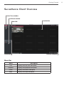
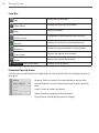
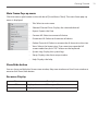
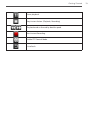
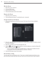
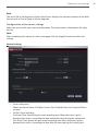
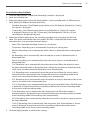
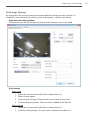
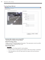
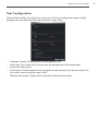
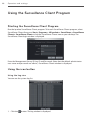
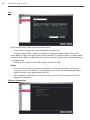
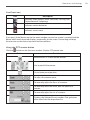
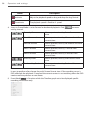
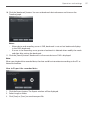
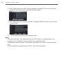
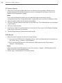
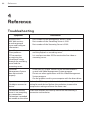
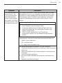
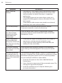
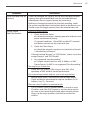
OWNER’S MANUAL
Video Management System
Please read this manual carefully before operating
your set and retain it for future reference.
MODELS
LVi510
1210 (V1.1)
2
Contents
1
Introduction
4Features
6
Recommended PC Requirements
6
Before install the Video Management System
2
Getting Started
7
Install the Video Management System
7
Starting the Video Management System
8
Management Tool Overview
9
Surveillance Client Overview
14
Management Server Overview
14
Recording Server Overview
15
Streaming Server Overview
3
Operation and settings
16
Using the Management Tool program
16
Using the overview window
17
Device Management
21
Server Management
28
User Management
3
30
Remote Setup settings
43
Device Upgrade settings
44
Map settings
46
License Management
47
Tool Configuration
48
Using the Surveillance Client Program
48
Starting the Surveillance Client Program
48
Using the icon button
52Live
55Playback
59Event
62Map
4
Reference
64Troubleshooting
4
Introduction
1
Introduction
The LG Video Management System is an IP-Surveillance software that works with the LG
Video Server and LG IP cameras to provide video monitoring, recording setting and event
management functions. The software has multiple search functions for recorded events.
Remote viewing and playback are also possible with the use of the Video Management
System.
This manual contains instructions on how to use and manage the LG Video Management
System in your networking environment. Some knowledge of networking environments
would be beneficial to the reader.
Should you require any technical assistance, please contact authorized service center.
Features
The LG Video Management System offers the following functions:
LG Management Server
•
DB(Database) management
•
User Authentication
Management Tool
•
Device Finder
•
Device grouping
•
Multiple tree view
•
Device Remote Setup
•
Recording Server Setup
•
User role & device access permission Setup
•
Real-Time Recording Server Monitoring
•
Map making & edition
•
Recording Calculator
•
Real-Time Streaming Server Monitoring
Introduction
•
Multiple device firmware update
Surveillance Client
•
256 Channels Live monitoring with video buffering
•
Multiple playback at the same time
•
Event recording search
•
Instant playback
•
Digital Zoom
•
Camera Pan/Tilt/Zoom Control (mouse, joystick support)
•
2 Way(Bidirectional) Audio support
•
Map support
•
Layout Sequence
•
AVI File export
•
Event Log
•
Intelligent Video analytics event detection
•
Map and Event Live Popup Display
•
LG IP Camera and DVR Support
Streaming Server
•
256 channels streaming
•
Real-Time live streaming
5
6
Introduction
Recommended PC Requirements
The LG Video Management System must be installed below operating systems for best
performance and stability.
Server Requirements(Recording Server, Streming Server, Management Server)
•
Intel® Xeon® E5620 2.6 GHz or Higher
•
4GB of RAM or Higher
•
500 GB of storage or more
Client Requirements(Surveillance Client, Management Tool)
•
Intel® i7-880 3.07 GHz or Higher
•
4GB of RAM or Higher
•
100 GB of storage or more
•
NVIDIA Geforce GTS450 1GB or higher ; PCI-E 2.0 x16 bus Graphics card with Microsoft®
DirectX
Operating System Requirements
•
Microsoft® Windows 7 Professional or Ultimate 32-bit/64-bit
•
Microsoft® Windows Server® 2008 Standard Edition SP2 32-bit/64-bit
•
Microsoft® Windows Server® 2008 Enterprise Edition SP2 32-bit/64-bit
•
Microsoft® Windows Server® 2008 Standard/Enterprise Edition R2 32-bit/64-bit
•
Microsoft® Windows XP Pro SP2/SP3 32-bit/64-bit
Warning:
Disable or Turn Off UAC (User Account Control) in Control Panel. It supports the Auto
Execution of Recording Server, Streaming Server and Management Server when Windows
Server has been rebooted. Do not use a login password when windows server is rebooted
because if you set the login password then the Recording server SW will not be restarted
automatically in rebooting.
Before install the Video Management System
•
The pictures used in this manual are based on Windows 7 Professional.
•
Do not use other applications with this Video Management System program. This can
cause memory shortage and program malfunction.
•
Check that the LG IP Device is(are) connected to the network and that power is supplied.
•
For more information on product installation, see the user manual of your LG IP device.
Getting Started
2
Getting Started
Install the Video Management System
You can install the Video Management System software following steps.
1. Insert the Program CD which will be started automatically.
If the disc does not run automatically on your PC, open the Program CD and install the
program manually.
2. Run the install file and install the programs to your computer following the on‑screen
instructions.
3. After finishing installation, you will find the programs in the start menu or on the desktop.
Starting the Video Management System
You can select and run the Video Management System program from your
Start>Programs>LG Ipsolute or click the each program icon on your desktop.
1. Run the Management Server.
2. Run the Recording Server.
3. Run the Streaming Server program. (Option)
4. Run the Management Tool program.
5. Run the Surveillance Client program.
7
8
Getting Started
Management Tool Overview
Main menu
Help
Main Menu Bar
Menu
Overview
Description
Displays the Camera Overview window.
Device
Displays the Camera Registration window.
Server
Displays the Server Registration window.
User
Displays the User Registration window.
Setup
Displays the Setup window.
Upgrade
Displays the Upgrade window.
Map
Displays the Map Registration window.
Help
Displays the help.
Getting Started
Surveillance Client Overview
Device Tree window
Live Event window
Live window
Menu Bar
Show/Hide
Resource display
Menu Bar
Menu
Description
Live
Displays the live view workspace.
Playback
Displays the playback workspace.
Event
Displays the event workspace.
Map
Displays the map workspace.
9
10
Getting Started
Icon Bar
Display the system logs.
Log
Displays the client setup window.
Client Setup
Displays the help.
Help
Change the screen format on the live view.
Screen Format
Displays the live view on the hotspot area.
Hotspot
Displays the layout rotation’s setup window.
Sequence
Displays the layout save window.
Save Layout
Displays the Export file Window.
Export
User Information
Displays the user group.
Liveview Pop-up menu
Click the mouse right button on the desired live view channel. The live view pop-up menu is
displayed.
•
Remove: Select to remove the selected device on the view.
•
Instant Playback: Just the time(second) ago to play recording
data.
•
Listen: Listen to audio from device.
•
Speak: Speak for sending audio into device
•
Digital Zoom: Enable digital zoom on images.
Getting Started
Main Frame Pop-up menu
Click the mouse right button on the title bar of [Surveillance Client]. The main frame pop-up
menu is displayed.
•
Tab: Select to main menu.
•
Selected Channel Print: Displays the selected channel.
•
Export: Exports the Data
•
Connect All: Select to connect all device.
•
Disconnect All: Select to disconnect all device.
•
Delete Channel all: Select to remove the all channel on the view.
•
View: Selects the layout view. If you want to escape the full
screen mode then push “ESC” button on the keyboard.
•
System Log: Display the system logs.
•
Setup: Displays the client setup window.
•
Help: Displays the help.
Show/Hide button
You can show and hide the Camera tree window, Map tree window and Live Event window at
once to click Show/Hide button.
Resource Display
Menu
CPU
Network
Description
Displays the current CPU usage of client.
Displays the current Network usage of client.
11
12
Getting Started
Live window icons
Icons
Description
Displays when the PTZ device is connected.
Displays when the audio function is activated in the network
device.
Indicates Continuous recording.
Indicates sensor recording.
Indicates motion detection recording.
Indicates va event detection recording.
Indicates instant recording.
Displays when the audio input function is available in the network
device.
Start Instant Playback. This function is playback previous 1 minute
image.
Getting Started
Pause playback.
Stop Instant Action. (Playback, Recording)
Play backward or forward by double speed.
Start Instant Recording.
Enable PTZ Control Mode.
List refresh.
13
14
Getting Started
Management Server Overview
When you start the management server, management server icon is displayed on the task bar.
Click the icon to start or stop server.
Recording Server Overview
When you start the recording server, recording server icon is displayed on the task bar. Click
the icon to start or stop server. If you click the Recording Server Status, the Recording Server
Status window is displayed.
•
Device Name: Displays the Camera name.
•
Framerate: Displays the frame rate. The frame rate is the number of transportable frames
per second.
•
Bitrate: Displays the Bit rate value.
•
Record: Displays the recording status.
•
Status: Displays the connection status.
Getting Started
Streaming Server Overview
When you start the streaming server, streaming server icon is displayed on the task bar. Click
the icon to start or stop server. If you click the Open streaming Server, the streaming Server
Information window is displayed.
•
Device Name: Displays the Camera name.
•
Framerate: Displays the frame rate. The frame rate is the number of transportable frames
per second.
•
Bitrate: Displays the Bit rate value.
•
Status: Displays the connection status.
15
16
Operation and settings
3
Operation and settings
Using the Management Tool program
The first time Management Tool is started, you should register a LG IP camera and Server(s) to
control it by the Video Management System.
Note:
The computer running Management Tool must be on the same network with device.
Using the overview window
•
Device: Displays the number of registered IP Camera and DVR. You can access directly to
click [Quick Access] button.
•
Server: Displays the number of registered Recording server and Streaming server. You can
access directly to click [Quick Access] button.
•
User: Displays the number of registered User by User Group(Administrator, Power, Normal).
You can access directly to click [Quick Access] button.
•
Map: You can access directly to click [Quick Access] button.
Operation and settings
•
Device Setup & Upgrade: Click [Remote Setup] button to access the Setup menu. And also,
click [F/W Upgrade] button to access the Upgrade menu directly.
•
License & Tool Configuration: Click [License] button to register or upgrade VMS software
license. If you click the [License] button, the license registration window will be displayed.
Device Management
Registration the device
1. Select the [Device] tab on the main menu or click the [Device] icon on the [Overview]
window. The Device window is displayed.
2. Click the [Scan] button. After a few seconds the found device is(are) displayed.
3. Select the device in the list. If you want to register the all device, check the [Select All]
option.
4. Click the [Add] button. The Device Add/Edit window is displayed.
5. Specify the Device Type, Device Name, Address type, IP Address, Port, User ID, Password,
Encryption, Stream, Protocol and click the [OK] button. If you select DVR on the Device
Type, Encryption, Stream and Protocol option is deactivated and you can select a DVR
model.
6. Click the [OK] button to exit the window.
The registered device is displayed in the Camera Group tree.
17
18
Operation and settings
Registration the device manually
1. Select the Device tab on the main menu or click the [Device] icon on the [Overview]
window. The Device window is displayed.
2. Click the [Manual Add] button. The Device Add/Edit window is displayed.
3. Specify the Device Type, Device Name, Address type, IP Address, Port, User ID, Password,
Encryption, Protocol and click the [Select] button.
4. Select the stream.
5. Click the [OK] button to exit the window.
Operation and settings
Registration the DVR
1. Follow steps 1-2 described in “Registration the device manually”.
2. Select to DVR on the Device Type.
3. Specify the Device Name, IP Address, Port, User ID, Password and Model. IP Address can
register IPv4 address only.
4. Click [Add] button. DVR Camera Add window is displayed.
5. Select to desired camera channel and click OK to add device.
19
20
Operation and settings
Edit the device
1. Select the device on the list.
2. Click the [Edit] button. The Device Add/Edit window is displayed.
3. Specify the Device Name, Port, User ID, Password, Encryption, Stream, Protocol and click
the [OK] button.
Remove the device
1. Select the device on the list.
2. Click the [Remove] button. The selected device is removed.
Create a new group folder and add the device
To create a device group under the selected folder, do the following on the Camera Group
Tree section:
1. Click the right mouse button on the folder.
2. Select the [Add Group] option. The Group Edit window is displayed.
3. Enter the group name.
4. Select the device to add the group folder.
5. Select the required device name that you want to group. If you want to add the all device,
check the [Select All] option.
6. Click the [<--] button.
7. Repeat steps 5 to 6 to group the other device.
8. Click the [Apply] button to confirm it.
The new group folder is created under the folder you selected.
Operation and settings
Delete a group folder
1. Select the required group folder and click the right mouse button.
2. Select the [Remove Group] option.
Notes:
•
It is not possible to delete the [System] folder.
•
Deleting a group folder will delete all subgroup folders within the group folder as well.
If you delete the group folder, the device in the group folder will be moved to the upper
group folder automatically.
Edit a group folder
1. Select the required group folder and click the right mouse button.
2. Select the [Edit Group] option. The Group Edit window is displayed.
3. Overwrite the existing group name with a new name of your want.
4. Add or remove the device.
•
If you add the device, select the device and click the [<--] button.
•
If you remove the device, select the device on the group list and click the [Remove]
button.
5. Click the [Apply] button to confirm it.
Note:
You cannot edit the [System] folder.
Server Management
Registration the Server
1. Select the Server tab on the main menu or click the [Server] icon on the [Overview]
window. The Server window is displayed.
2. Click the [Add] button. The Server Add/Edit window is displayed.
3. Specify the Server Type, Server Name, Server IP and click the [OK] button.
4. Click the [OK] button to exit the window.
21
22
Operation and settings
Edit the Server
1. Select the server on the list.
2. Click the [Edit] button.
3. Specify the Server Name.
4. Click the [OK] button to exit the window.
Remove the Server
1. Select the server on the list.
2. Click the [Remove] button. The selected server is removed.
Assign the device to the Server
1. Click the [Assign] button of the Server menu. The Server Device Assign window is
displayed.
2. Select the required device on the Device List. If you want to assign the all device, check
the [Select All] option.
3. Select the recording server from the drop-down list.
4. Click the [ ] button. If you want to release it, select the device or check the [Select All]
option and then click the [ ] button.
•
Current recording device/Total recordable device: Indicate the number of current
assigned device and recordable device on the basis of license.
5. Click the [OK] button to exit the window.
Device Status setting
You can check the current device status. If you want to check the abnormal device status,
press the [Status] button and then you can view the result on the [Server Status] column.
Operation and settings
Note:
The value (OK or No Response) of the Device Status displays the activate condition of the Web
Service such as Device Setup or Device Upgrade.
Configuration of the server settings
Select the server which you want to configuration. The setup menu is displayed on the right
column.
Note:
After completing the settings on each setup page, click the [Apply] button to confirm the
settings.
General settings
>> Server Information
Shows the Server Name, IP Address, Access Port, Playback Port and Assigned Device
number.
>> Pre/Post Event Recording
•
Pre Event Time: Specify the pre-event recording time. When the Event signal is
detected, the server is recording the data before the event during the setting time.
•
Post Event Time: Specify the post-event recording time. When the Event signal is
detected, the server is recording the data after the event during the setting time.
23
24
Operation and settings
>> Auto Execution
•
Select the [Use] option to start the recording server automatically when you restart
the system.
Notes:
•
If you use this option, you should deactivate the UAC function of the Recording
Server.
•
If the recording server is set to password, this function is not activated.
•
Do not use a login password when windows server is rebooted because if you set
the login password then the windows server won’t be restarted automatically in
rebooting.
Storage settings
>> Add the recording drives
1. Click the [Add Local Drive] or [Add Network Drive] button.
2. Set the detail options.
•
•
[Add Local Drive] options.
--
Local Drive: Selects the local HDD drive of your recording server.
--
Directory: Enter the folder name to save the recorded data files.
[Add Network Drive] options.
--
Drive: Selects the network drive name.
Operation and settings
--
Folder: Enter the network drive address with folder name.
--
User ID: Type the user ID for the folder access in the Network drive.
--
Password: Type the password for the folder access in the Network drive.
3. Click the [Add] button.
>> Recording and playback device setting
1. Select the device on the device list.
2. Click the [Edit] button. If you want to edit the 1 more device, click [Multi Edit]
button. The Recording Setup window is displayed.
3. Set the options.
•
Recording: Check to enable the Storage device recording. If you select this, the
Drive and Capacity options are activated.
•
Overwrite: Select when allow the overwrite recording. This function is possible
when the selected Storage device has fully recorded.
•
Drive: Select the recording drive.
•
Address, Directory: Displays the address and folder information of the selected
drive.
•
Capacity: You can set the limit data capacity of the folder to record the data.
4. Click the [OK] button.
>> Calculate the storage
Select device and click the [Calculator] button. The IP Calculator window is displayed.
Click [Calculate] to confirm the enable recording days and storage space.
25
26
Operation and settings
Warning:
The calculated data can change to other value according to a video image scene
including motion vector.
Schedule settings
Operation and settings
To set the Recording Schedule
1. Click the [Add] button. [Schedule of Recording] window is displayed.
2. Enter the schedule alias.
3. Select the repeat type and set the detail options. It can be configured in 5 different ways,
Daily, Weekly, No Repeat, Monthly and Yearly.
•
Schedule duration: If the [Repeat type] option set to [No Repeat], [Monthly] or [Yearly],
this option is displayed.
•
Custom day: If the [Repeat type] option set to [Monthly] or [Yearly], this option
is displayed. When you set the [Custom day], the Management Tool can run the
recording at a designated day only.
4. Select the record mode and set the recording schedule time using drag on the time
table. The record mode differ from the model. The VMS is displayed the record mode
automatically as the connected network device.
•
None: The scheduled recording function is not activate.
•
Continuous: Recording starts automatically from the pre-setting time.
•
Motion: Recording starts automatically when motion is detected within a designated
time.
•
VA: Recording starts automatically when the object or event is detected within a
designated time.
•
Sensor: Recording starts automatically when the sensor input is activated within a
designated time.
•
C+V: Recording starts automatically from the preset time. When the object or event
has been detected within a designated time, change the continuous recording mode
to VA event recording mode and recording starts automatically.
•
C+S: Recording starts automatically from the preset time. When the sensor input is
activated within a designated time, change the continuous recording mode to the
sensor event recording mode and recording starts automatically.
•
V+S: Recording starts automatically when the object or event is detected or the sensor
input is activated within a designated time.
•
C+V+S: Recording starts automatically from the preset time. When VA or SENSOR event
is detected, change the continuous recording mode to the VA event recording mode
or the sensor event recording mode.
•
C+M: Recording starts automatically from the preset time. When the motion is
detected within a designated time, change the continuous recording mode to motion
event recording mode and recording starts automatically.
•
M+S: Recording starts automatically when the sensor alarm signal has input or motion
has been detected.
•
C+M+S: Recording starts automatically from the preset time. When Motion or Sensor
event is detected, change the continuous recording mode to the motion event
recording mode or the sensor event recording mode.
5. Click the [Apply] button to confirm the settings.
27
28
Operation and settings
To edit the Recording Schedule
1. Choose the Schedule Alias in the Schedule list.
2. Click the [Edit] button.
You can check or change the recording schedule options except for [Repeat Type] and
[Alias].
To delete the Recording Schedule
1. Choose the schedule in the Schedule list.
2. Click the [Delete] button in the Schedule list.
To activate the Recording Schedule
1. Select the device from the drop-down list of the [Select Device] option.
2. Choose the Schedule Alias in the schedule list and then click the [Allocate] button.
To deactivate the Recording Schedule
1. Choose the schedule in the Camera list.
2. Click the [Delete] button in the Camera list.
Note:
If you select the “Allocate to all” option, the connected device will be set to the same schedule.
User Management
Registration the new user
1. Click the [User] icon of the Main menu or [Overview] window.
2. Click the [Add] button. The User Add/Edit window is displayed.
3. Specify the User Group, User ID, Password and click the [Apply] button.
•
Administrator: Allows you to operate setup menus as default and you can not set to
disenable it.
•
Power: Allow operating Live Monitoring and PTZ Control as default and you can not
set to disenable it. Playback, Map and Event Search options are able to set to click to
check box.
Operation and settings
•
Normal: The Normal user is able to use the Live Monitoring function only and can not
to customize.
4. Click the check box if you control permissions of the Surveillance Client.
•
Live Monitoring: Click the check box if you use the Live tab on the Surveillance Client
Program.
•
Playback: Click the check box if you use the Playback tab on the Surveillance Client
Program.
Note:
If you do not have the permissions, you can not use the Instant play function about
playback.
•
Map: Click the check box if you use the Map tab on the Surveillance Client Program.
•
PTZ Control: Click the check box if you use the PTZ Control on the Surveillance Client
Program.
•
Event Search: Click the check box if you use the Event tab on the Surveillance Client
Program.
5. Click the [Apply] button to exit the window.
The registered user is displayed in the Users tab.
Edit the user
1. Click the [User] icon of the Main menu or [Overview] window.
2. Select the user on the list.
3. Click the [Edit] button.
4. Specify the User Group, Password and click the [Apply] button.
Note:
You can not edit the User ID.
Remove the user
1. Click the [User] icon of the Main menu or [Overview] window.
2. Select the user on the list.
3. Click the [Remove] button. The selected user is removed.
Note:
You can not remove the admin user ID.
29
30
Operation and settings
Assign the device to the User
1. Click the [Assign] button of the User menu. The User Device Assign window is displayed.
2. Select the required device on the device list. If you want to assign the all device, check the
[Select All] option.
3. Select the user from the drop-down list.
4. Click the [ ] button. If you want to release it, select the device or check the [Select All]
option and then click the [ ] button.
5. Click the [OK] button to exit the window.
Remote Setup settings
You can set the device via the network.
1. Click the [Setup] icon of the Main menu or [Overview] window.
2. Select the device name.
3. Click the [Setup] button. The remote setup window is displayed.
4. Set the options.
Note:
After completing the settings on each setup page, click the [Apply] button to confirm the
settings.
Operation and settings
Video Setup
General
Standard
Displays the video system of the device.
CaptureMode
This item is optional. Select the capture mode.
Motion
Motion detection window is used to detect movement of the object in the video image.
Motion detection is used to generate an event whenever movement occurs in the video
image. A total of 5 motion detection windows can be configured.
1. Select Motion Detection window number from the drop-down list.
2. Click one point with the left mouse button on the preview window and drag &
drop to adjust the desired size. The Motion detection window will appear in the
video window. If you set to all area, click the [All] button.
3. Set the Sensitivity value. The higher Sensitivity value is set, the smaller motion can
detect.
31
32
Operation and settings
Notes:
•
You can reset the size and position of the Motion detection window. Click one of
the dot point and drag & drop to adjust the motion detection area. Click the Motion
detection window and drag to the desired position.
•
If you want to delete the Motion detection window, select window number and click
the [Remove] button.
•
Motion Detection is activated when the Video Codec is set to [H.264] only.
H.264 & MJPEG
Enable
Click to activate the stream function.
Deinterlacing
Click to use the deinterlacing function.
Maximum Frame Rate
Select the frame rate.
NTSC
1 to 30 (fps)
PAL
1 to 25 (fps)
Quality
Select the Quality.
--
VBR: The bit rate may vary depending on the complexity of the video to
meet the selected quality.
--
CBR: The video quality may vary in order to preserve a constant bit rate.
Stream Quality
If the [Quality] option set to VBR, this option is displayed. Select the network stream
quality. (HIGHEST, HIGH, MEDIUM, LOW and LOWEST)
>> Bit rate: If the [Quality] option set to CBR, this option is displayed. Enter the bit
rate. Edit the bit rate value from 256 kbps to 10 240 kbps.
>> GOP Size: Select the GOP size. This setting is valid for H.264.
Operation and settings
VA(Video Analytics) Configuration settings (Option)
You will need professional knowledge to set VA Configuration functions. You must be careful
to change the options.
Video analytics is possible to detect specific events. Video analytics makes it possible to filter
video when you defined events have been detected.
Activate video analytics processing at DSP
Check the box to enable the video analytics.
Preset Mode
It provides multiple pre-defined configuration data sets each are proper to the condition
of the environment where surveillance device are located.
Location
Select the location from the drop-down list.
Lightness
Select the lightness from the drop-down list.
33
34
Operation and settings
Distance
Select the Distance from the drop-down list.
Note:
After the location option have been selected, you can set the lightness and distance
options.
If these options are set, the Basic and Advanced parameters are set automatically to
default value.
OSD
Tracking box
Check the box to display the object tracking box. The object tracking box is displayed
with green color on the preview window.
ID
Check the box to display the object tracking ID. The object tracking ID is displayed
with white color on the preview window.
Contour
Check the box to display the object contour. The object contour is displayed with blue
color on the preview window.
(contour check box enabled when “Activate” in advanced parameters.)
Trajectory
Check the box to display the object trajectory. The object trajectory is displayed with
red color on the preview window.
Filter
You can set the filter size for tracking the object within the filter box.
None
Selects when you do not use this function.
Normal filter
Objects whose size are out of the range between Minimum size and Maximum size will
be filtered.
If you select this option, the blue and pink box is displayed on the preview window.
Click on the edge of a box and drag it larger or smaller as required. Click on the other
edge of the box and drag it larger or smaller to resize it appropriately.
>> Blue box (Maximum pixel size) : This option determines the maximum size of
the objects to be filtered among the final detection results.
>> Pink box (Minimum pixel size) : This option determines the minimum size of
the objects to be filtered among the final detection results. (Display pink box in
preview)
Operation and settings
Perspective filter
For certain video analytics, use the perspective filter function.
If you select this option, the blue and pink box is displayed on the preview window.
Click on the edge of a box and drag it larger or smaller as required. Click on the other
edge of the box and drag it larger or smaller to resize it appropriately.
>> Pink box (Perspective plane polygon): This parameter determines the
perspective plane.
>> Blue box (Mini size polygon): This option determines the minimum size of the
objects to be filtered among the final detection results.
Basic Parameters
Basic parameters are direct related for the video analytics.
Object Detection
>> Detection sensitivity: Select the sensitivity to detect the object. If this option
is set as relatively high value, even a slight local change in the scene will be
detected as an object and vice versa.
Object Tracking
>> Strictness: Select the strictness for object tracking. If this option is set as
relatively low value, system will track objects even though the similarities of
objects between frames are low and vice versa.
Advanced Parameters
For more detailed parameter settings, use these options.
Object Detection
>> Detection sensitivity: Selects the sensitivity to detect the object. If this option
is set as relatively high value, even a slight local change in the scene will be
detected as an object and vice versa.
>> Grouping sensitivity: Selects the grouping sensitivity for the degree of
‘Grouping sensitivity’. If this option is set as relatively high value, local changes
which are proximally positioned in the scene will be grouped as one object
and vice versa.
Object Tracking
>> Strictness: Selects the strictness for object tracking. If this option is set as
relatively low value, system will track objects even though the similarities of
objects between frames are low and vice versa.
>> Search Range: Selects the search range of ‘tracking’. If this option is set as
relatively low value, system will search the small range of region to track the
objects in next frame and vice versa.
>> Count for withdrawal: Selects the time to make decision for object’s withdrawal
in the scene. If this option is set as relatively low value, system will decide the
withdrawal of objects in small amount of time and vice versa.
35
36
Operation and settings
Background Modeling
>> Learning time: Selects the Learning time when the tracking loss occurred.
If this option is set as relatively low value, the background learning will be
carried out in a short time interval and vice versa.
Shadow Removal
>> Activate: Check to activate the shadow removal function. If this option is set,
the region classified as shadow will be filtered among the final detection
results and vice versa.
>> Variance of shadow: Selects the maximum variance of the color of the shadow
region. If this option is set as relatively low value, the region with uniform color
will only be classified as shadow and vice versa.
Blind Update
>> Activate: Check to activate the blind update function. If this option is set,
detected objects with little movement progressively will be recognized as the
environment after certain amount of time (blind update). If this parameter
is not set, detected objects will never be recognized as the environment
(selective update).
>> Speed: Selects the blind update speed. If this option is set as relatively high
value, objects with little movement will be recognized as the background fast
and vice versa.
Camera Tampering
>> Sensitivity: Selects the sensitivity of ‘Camera Tampering’. If this option is set as
relatively low value, the system will dully detect the movement, the veiling of
device and vice versa.
Contour
>> Activate: Check to activate the contour function. If this option is set, contour
processing is on at DSP and detected objects with contour will be display. If
this option is not set, contour processing is off at DSP and detected objects
with contour will never display.
•
Restart background modeling
Compulsorily initialize the background model and make the system to learn the
background.
•
Initialize VA
Initializes the VA options as default values.
•
Apply
After completing the settings on this page, click [Apply] button to confirm the settings.
•
Cancel
Cancels the setting of current values.
Operation and settings
VA Settings (Option)
By setting the rules, you can manage the event detection settings per each device. It is
available to save maximally 10 rules at a time and to apply 1 rule per each device.
Open the rule setting window
If the device have the VA function, the Event (Video Analytics) icon is activated.
Rule settings
Make a rule
1. Select the rule name from the Rule List drop-down list.
2. Select a name option.
3. Overwrite the existing rule name with a new name of your want.
4. Click the [Rename] button. The new name is added in the Rule list.
Delete the rule
1. Select the rule name from the Rule List drop-down list.
2. Click the [Delete] button. The rule name is deleted in the Rule list.
37
38
Operation and settings
Enable the rule
1. Select the rule name from the Rule List drop-down list.
2. Click the [Enable] button.
Disable the rule
1. Select the rule name from the Rule List drop-down list.
2. Click the [Disable] button.
Event settings
Set the event options for the Rule.
1. Select the event type from the drop-down list.
--
Intrusion Event: When the perceived object is(are) move into the event area,
the Intrusion Event is activated.
--
Crossing Line Event: When the perceived object go through a setting lines, the
Crossing Line Event is activated.
--
Object Counting Event: When the perceived object go through a setting line,
the Object Counting Event is activated.
--
Object Removal Event: When the object is disappear from the setting area, the
Object Removal Event is activated.
--
Tampering Event: When the device condition is changed such as the screening
device or shaking the image and so on. (You can set this function for once).
2. Select the event from the Event List drop-down list.
Note:
If you want to change the event name, select the Name option and overwrite the
existing name with a new name. Click the [Rename] button.
3. Set the event area on the preview window using the event tool button.
Use for Intrusion and Object Removal event.
You can set the rectangle event area.
Use for Intrusion and Object Removal event. You can set the
polygon event area. (The maximum number of polygon’s
vertex is constrained to 32).
Use for Crossing Line event.
Draw the line for crossing line event. Yellow and black arrows
will be displayed at the center of line. Two arrows mean the
event-triggering direction. Default setting is bi-direction.
If you want to change it to single direction, select yellow
direction or black direction button.
Operation and settings
Use for Object Counting event. Draw the line for Object
Counting event. Yellow and black plus (+) symbols will be
displayed at the center of line.
Yellow and black color means direction of passing object. (+)
symbol and (-) symbol mean the plus and minus counting
respectively. Thus default setting is bi-directional plus
counting. If you want to change the default setting, select
another option. Additionally, you can set the limit of counting
with Max Count.
Use to delete the saved event.
4. Click the [Event Save] button to save the settings.
Filtering maximum size of object
Set the filtering size of the object. The maximum filtering size is displayed with blue
color on the preview window.
>> Width of object: Adjusts the vertical filtering size of the object.
>> Height of object: Adjusts the horizontal filtering size of the object.
Filtering minimum size of object
Set the filtering size of the object. The minimum filtering size is displayed with pink
color on the preview window.
>> Width of object: Adjusts the vertical filtering size of the object.
>> Height of object: Adjusts the horizontal filtering size of the object.
39
40
Operation and settings
Tracking Setup (Option)
Activate video analytics processing at DSP
Check the box to enable the video analytics.
Auto PTZ Tracking setting
Configure Auto PTZ Tracking Algorithm Parameters. These parameters are to be used for
tracking the object displayed on the screen.
Auto PTZ Main Menu
Track Mode
Configuration of tracking modes for moving objects.
>> PT : This mode uses Pan/Tilt and tracks objects while auto tracking is conducted.
>> PTZ : This mode uses Pan/Tilt/Zoom and tracks objects while auto tracking is
conducted.
Operation and settings
Target Size
Configuration of how large the object being tracked is actually displayed on the
screen.
>> SMALL : This mode zooms in and magnifies the object until it occupies 1/4 of the
screen.
>> MEDIUM : This mode zooms in and magnifies the object until it occupies 2/4 of the
screen.
>> LARGE : This mode zooms in and magnifies the object until it occupies 3/4 of the
screen.
Camera Height
Configures the height of the camera.
Track Time
Configures maximum time duration of tracking. The system starts tracking when it
detects objects in motion. As the time reaches the maximum time duration configured
by user, the tracking is disabled and the camera returns to its initial position. The
system will be reset for tracking new objects. You should be aware not to set up the
time duration too short since it may cause tracking failure.
Sensitivity
You can configure the sensitivity of detection. Choosing proper sensitivity will enhance
the performance of auto tracking since the environmental condition may influence
the accuracy of the detection. For instance, rain, snow, or swaying branches may cause
malfunctioning of auto tracking.
>> LOW: The sensitivity of the object detection is LOW. In this case, false detection rate
is also low, but if the object itself is too small or very similar to the background, it
may not be detected.
>> MEDIUM: The sensitivity of the object detection is middle. The camera detects
the object more accurately than the case of low sensitivity. It may detect swaying
branches or flags, but not frequently.
>> HIGH: The sensitivity of the object detection is HIGH. The camera can detect even
smaller one, but it can also detect swaying branches or flags. Additionally, rain or
snow may decrease the accuracy of the detection.
Auto PTZ Lost Menu
Action
You can configure next step when the camera lost the object which has been tracked.
>> STAY : When the camera loses the object, it doesn’t come back to its initial position,
but stays where the object has been just lost.
>> RETURN : When the camera loses the object, it returns to its initial position and
gets ready to detect new object.
Time Out
When the camera lost the object for the first time, it zooms out twice and tries to track
the object. Time Out variable, after the camera zooms out twice, sets how long the
camera maintains the status of the object detection to re-detect it.
41
42
Operation and settings
•
Apply
After completing the settings on this page, click [Apply] button to confirm the settings.
•
Cancel
Cancels the setting of current values.
Operation and settings
Device Upgrade settings
You can update the device manually.
1. Select the device on the Device list. If you want to upgrade the all device, check the [Select
All] option.
2. Click the [Path] button.
3. Find and open the firmware file.
4. Click the [Upgrade] button to update the firmware.
Note:
Multi device upgrade needs more time than single device upgrade. So upgrade time has
relation to number of device or VMS status. But this operation is useful for management of
much device.
43
44
Operation and settings
Map settings
This function gives a visual overview of the device in your surveillance environment.
Map setup icon
Map View
Map List
Map View Mode selection icons
When the icon is clicked, the screen will be changed to split mode. Choose the Map View
mode.
Map setup icon
Click to setup the Map options.
Add Map
Click to add the map.
Edit Map
Click to modify the map.
Remove Map
Click to remove the map
Device Mapping Click to allocate and edit the map.
Map List
Displays the imported Maps.
Map View
Displays the registered Maps.
Operation and settings
Add the Map
1. Select the map as parent on the Map list.
2. Click the [Add Map] button and specify the name.
3. Select the file to register the sub-map of the selected map.
Edit the Map
1. Select the required Map.
2. Click the [Edit] button. The [Map Add/Edit] window is displayed.
3. Edit the device position, Map name or delete the device.
4. Click the [OK] button to exit the window.
Delete the Map
1. Select the required Map.
2. Click the [Delete] button. The selected Map is deleted.
Device Mapping
1. Select the map on the Map List.
2. Drag and drop the device on the selected map, after click the [Device Mapping] icon.
Rotate the device image
1. Select the map on the Map List and click the [Device Mapping] icon.
2. Select the desired device and click mouse right button to select the Rotate menu and
desired angle.
Remove the device image
1. Select the map on the Map List and click the [Device Mapping] icon.
2. Select the desired device and click mouse right button to select the Remove menu.
45
46
Operation and settings
License Management
Registration the License
1. Click the [License] icon of the [Overview] menu. The [License Registration] window will be
displayed.
2. Click the [Select] button.
3. Find and open the License file.
•
License Type: Indicates the type of license.
•
Server Mac: Indicates the Hardware Mac address of Work Station where Management
Server installed.
•
Authorized Date: Indicates the date when the license is authorized.
•
Expire Date: Indicates the date when current license is expired.
•
Total Devices: Indicates the number of registerd all of device on the device list.
•
Recording Devices: Indicates the number of assigned device on the Recording Server.
Note:
•
IP camera is counted 1 device as 1 and DVR is counted 1 device as 0.25 on the
Recordable Device.
•
The Recordable Devices is fixed 16 automatically when the Expire Date is elapsed.
And you can not assign device on the recording server. To record more device, you
have to renew the license.
4. Click the [Close] button to exit the window.
You can use the all channels without limitation.
Operation and settings
Tool Configuration
Click the [Tool Config.] icon of the [Overview] menu. The Tool Configuration window will be
displayed. You can select the Auto Login and Auto Logout Status.
•
Language: Displays the language of the Management Tool.
•
Auto Login: If you select [Use], you can start the Management Tool automatically
as pre-executed account.
•
Auto Logout: The Management Tool is logged out automatically if you do not conduct the
user mouse input during the Logout Time.
•
Software Information: Displays the version of the Software Information.
47
48
Operation and settings
Using the Surveillance Client Program
Starting the Surveillance Client Program
Run the Ipsolute Surveillance Clicent program. To launch Surveillance Clicent program, select
Surveillance Clicent from your Start > Programs > LG Ipsolute > Surveillance > Surveillance
Clicent > Surveillance Client or click the Surveillance Clicent icon on your desktop. The
Surveillance Client login window is displayed.
Enter the Management Server IP, User ID and Password. (Note that the default administrator
user name and password are “admin”.) Surveillance Clicent window is displayed.
Using the icon button
Using the Log view
You can see the system log list.
1. Click the
button. The log window is displayed.
Operation and settings
2. Click the [Calendar] button and select the day and time. (The selectable days are displayed
in green color.)
3. Click the
button.
4. Use [Prev] or [Next] to see the previous or next log list. If you move to the beginning page
of the log list, click the [First] button.
5. Click the [Export] button to download a text log file.
Note:
The system log is system log data of Recording Servers which record current selected device.
Therefore, the system log can not export when is disconnected with recording server.
Client Setup settings
Click the
button. The Client Setup window is displayed.
General
•
Language: Select the language.
•
DVR Playback: If you configure the recording setting, recording server and DVR is executed
recording same time. Select [Recording Server] or [DVR] when you request recorded data
on the surveillance client.
•
OSD: Check [On] or [Off ] to select the OSD.
•
Guide Popup: Check the Guide popup option to display popup when each tab switched
•
Event Sound: Check the sound [On] or [Off ] when an event occurs.
•
Target Export Folder: Set the export path. The default path is like as below.
--
Image Export: .../LG Ipsolute/Surveillance/Surveillance Client
--
Video Export: .../LG Ipsolute/Surveillance/Surveillance Client
--
Log Export: .../LG Ipsolute/Surveillance/Surveillance Client
49
50
Operation and settings
Live
•
•
Video Aspect Ratio: Select the video output ratio.
--
Fit to Screen: Displays the video according to screen size.
--
Original Aspect Ratio: Displays the video according to original video source ratio.
Video Buffer: Displays the each status of device buffer. This option displays smooth video
playback. Each video is buffered during set time. And also, each frame is displayed evenly
in a certain time.
--
Buffering Time: Adjusts the buffering time of the live video.
Notes:
•
If you use this function, the amount of buffer is increased and video is delayed as
much as set time. Therefore, it is recommend not to occur the video delayed. Video
Buffer function is not supported to the DVR.
•
After setting of the [Buffering Time], you have to restart the Surveillance Client for
operate the program.
Software Information
Operation and settings
Displays the version of software.
Screen Format
Click the
button. The view window is displayed. Select the desired Screen Format. The view
is changed selected Screen Format.
Hotspot
Click the
button. The selected Hotspot channel is displayed purple border and image of
selected channel is copied to the hotspot channel.
Sequence
Click the
button. The Rotation window is displayed and view all the channels in sequence
in the selected Screen Format. Click
or
to allocate the layout what the desired Screen
Format and information of device mapping.
51
52
Operation and settings
Save Layout
Click
button to store the mapping information after set the surveillance device on the
desired Screen Format. Enter the layout name and click OK. The icon is created on the device
tree window.
Select the layout icon to browse the desired layout. If you want to delete the layout, select the
layout and click mouse right button. The popup menu is displayed and you can select delete
to delete the layout.
Live
1. Click the [Live] tab to see the live view.
2. Select registered device or group on the device tree, and then drag and drop the Live view
window.
3. Mapping device will be connected automatically.
Operation and settings
Live Event icon
Icon
Description
Indicates Video Analysis Event. (Intrusion, Crossing Line,
Object Removal, Tampering)
Indicates motion detection
Indicates sensor event.
Note:
If you press [Auto] button on the live event window, current live screen is removed and the
device which event occurred displays sequentially on the screen. Device drag and drop
function can not do when auto event function perform.
Using the PTZ remote button
Click the
button on the live view window. Displays PTZ camera icon.
Button
Function
Remove the PTZ virtual remote control.
Use to pan/tilt the camera.
Go to Home preset position
To adjust the camera zoom.
To manually adjust the focus of a camera.
To manually adust the zoom, pan, tilt speed of a
camera.
To manually adjust the iris of a camera.
Displays the Selected Preset number. Click go button
after select from the drop down list.
53
54
Operation and settings
•
Add: Add the preset position number.
•
Delete: Delete the preset position number.
•
Set Tour: To set the preset tour.
•
Tour: To start a preset tour.
•
Group Tour: To start preset group tour.
•
Record: To start a pattern record.
•
Run: To start a recorded pattern.
Displays the Camera OSD control window.
Use these buttons to setup the Camera. This button
does not appear on the screen if the login is other than
the administrator.
Displays the Information Area.
Notes:
•
PTZ Control can not use the specific function depend on the model. DVR is able to set the
PTZ Control for OSD setting. Click [Enter] Button on the OSD Control and set the position
using by PTZ arrow button and Iris +, – button.
•
PTZ is supported to USB Joystick and it is recommended to use IP Desktop of the CH
Products Company. (Web site: http://www.chproducts.com/13-28464-Home.php)
•
The stream of Live view is depends on the screen format.
HD profile only
Most wide channel is connected HD profile,
others are connected to SD profile.
•
When the Live view channel can not be connected to SD profile, it is connected to HD
profile only.
•
It is connected to HD profile only when the [Sequence] run.
Operation and settings
Playback
You can playback the recorded data of a selected IP device. To start playback, you should
check the recording server condition in the management tool.
1. Select the [Playback] tab.
2. Click the channel number and drag and drop to playback window position. If you select
[Device] and drag and drop to a playback window then all channels are displayed.
3. Select the channel window you want to view.
4. Select playback start time by using the time line and time input column. When using time
line to search a start time, use the zoom in/out icons for more detailed searches.
5. Click the date icon and select the date. The day is displayed in a green text when recorded
data exists.
6. Start playback and adjust the speed up to x8 by using the Jog Control(
). You can
backward and forward play to drag left and right. The Jog control can adjust the speed
more than x1 only.
7. The Jog Control Rock button status is like as below.
55
56
Operation and settings
Status
Description
Activate
Adjust the playback speed to drag and drop the Jog Control.
Deactivate
The playback speed is fixed to x1 speed.
8. Jump to Frame Mode is set to forward or backward playback. Click
setting interval.
to move
Frame by Frame
Moves previous/next by frame from current
time.
Next 10 seconds
Moves previous/next by 10 seconds unit from
current time.
Next 30 seconds
Moves previous/next by 30 seconds unit from
current time.
Next 1 minutes
Moves previous/next by 1 minute from
current time.
Next 5 minutes
Moves previous/next by 5 minutes from
current time.
Event by Event
Moves previous/next by Event from current
time.
Bookmark by Bookmark
Moves previous/next by Bookmark from
current time.
Note:
It must to perform after change the multi Screen Format view. If the recording server is
DVR, although the playback is searched the current camera is not watching when the DVR
camera move to previous or next frame.
9. Event Mode(
) is function which the Timeline graph set to be displayed specific
recording information only.
Operation and settings
10. Click the [bookmark] button. You can set bookmark desired camera and time on the
Timeline graph.
Notes:
•
When device and recording server is DVR, bookmark is not set but bookmark displays
in the DVR’s bookmark.
•
If server is the Recording server, previous bookmark is deleted when modify the mode
and date after setting the bookmark.
11. Click the [Search] button. Bookmark list of current device or DVR is displayed.
Note:
When you playback the recorded data, the data could be intermittent according to the PC or
Network condition.
How to Export the recorded data
1. Click the Export button. The Export window will be displayed.
2. Select Image or Video.
3. Click [Save] or [Start] to save the export file.
57
58
Operation and settings
3-1.Click [Image] button, the [JPEG Saving] window is displayed. Click [Save] to save the
export file. The image format is fixed to the JPEG format.
3-2.Click [Video] button, the [Export] window is displayed. Select a format and click [Start]
to save the file.
3-3. Click [Print] button to print the selected screen.
Notes:
•
The audio recording is not supported when the DVR Camera is recorded video on the
recording server. Therefore, the exported file is not supported audio.
•
The exported video file where is recorded on recording server can be run the File player
only.
•
Only the video data of playback time within 1 hour can be exported.
Operation and settings
Event
You can search event log history.
Playback View
Page View Icon
Map View
•
Playback View: When you select a log, you can see the playback in playback view. If you
want to pause the playback, click the
Button. If you want to control the playback in
detail, click the Button.
•
Map View: When you select a log, you can see the map in map view. If you want to see the
map that is shown in new map tab, click the
Button.
•
Click page view icon to see the log search list.
Icon
Description
First
Go to the first event log page.
Previous
Go to the previous event log page.
Next
Go to the next event log page.
Last
Go to the last event log page.
•
After event search success, when you mouse right click on the log list, you can see the [Go
to Live] Context Menu. If you want to see the searched device in new live tab, you click the
[Go to Live] Menu.
•
If the Recording server checked in the IP Camera or DVR Search, Edit button which display
the current page is activated. Enter the desired page and click enter to move the page.
59
60
Operation and settings
IP Camera Search
1. Select the [Event] tab and desired camera on the device tree window. The device tree
window displayed list of allocate device. Layouts is displayed list of layout. Each list of
device can management as group.
Note:
If you want to allocate the device to user and add to device on group, use the
management tool. The setting information is applicable when start the Surveillance Client.
2. Select the device name on the device tree window.
3. Click the [Calendar] button and select the day and time. (The selectable days are displayed
in green color.)
4. Click the [Search] button.
5. Use [Prev] or [Next] to see the previous or next log list. If you move to the beginning page
of the log list, click the [First] button.
6. Click the Export button to download a text log file.
DVR Search
1. Select the search location to click the [Setup] button.
1-1.If you want to DVR Search in Recording Server, check the [Recording Server] option on
the [Client Setup > General > DVR Playback].
1-2.If you want to DVR Search in DVR, check the [DVR] option on the [Client Setup >
General > DVR Playback].
Note:
When you check the [DVR] option on the [Client Setup > General > DVR Playback], DVR
Search result has no thumbnail images.
2. Follow steps 1-6 described in “IP Camera Search”.
Operation and settings
Smart Search
1. Select the device name on the device tree window.
2. Click the
button. The Smart Search window will be displayed.
3. Click the [Calendar] button and select the day and time. (The selectable days are displayed
in green color.)
4. Set the search area by mouse drag in preview for smart search.
5. Choose the Sensitivity value.
6. Click the [Search] Button.
7. Click the
button to stop the smart search.
Note:
DVR Search result has no thumbnail images.
How to Export the event log data
1. Click the Export button. The Export window will be displayed.
2. Click OK to save the text file.
61
62
Operation and settings
Map
This function gives a visual overview of the device in your surveillance environment. You can
add the map to drag and drop the device to the map view.
Map Navigation
Previous Map
Move
Icon
•
Description
Screen Format
Screen Format Change (1 Screen Format to 4 Screen
Format)
Go to Live
See the device of selected map in new live tab.
Go to Playback
See the device of selected map in new playback tab.
Save Layout
Save Current Layout.
Previous map
Click this button to move to upper map.
Move
When it activated, you can move the map if map is
zoom in.
Map Navigation: Show the map path. When you click map navigation, context menu is
displayed as map name of same level. Click the map to move desired map.
Operation and settings
•
Live Popup: When you double click the device in map or the event is occurred, popup the
live streaming window.
•
Event Popup: When the event is occurred, icon changed from
to
, and the live
popup is displayed. Event is not occurred in a certain time, icon is changed from
to
•
If you can zoom in or zoom out using by the mouse wheel, also you can zoom in or zoom
out using by or button.
63
64
Reference
4
Reference
Troubleshooting
Symptoms
Resolutions
Use the SOAP/
XML Web services
to exchange each
server and configure
information.
•
Port number of the Management Server is 9100.
•
Port number of the Recording Server is 9101.
•
Port number of the Streaming Server is 9102.
Surveillance
Client performs
TCP connection
by receiving the
surveillance image
through the recording
server and the
streaming server.
•
It is used port number 554 for the request of recorded data
and the playback as recording server.
•
It is used port number 555 for receive the live video as
streaming server.
The Video
Management System
does not activate
properly
•
Check your PC system. Please use the recommended PC
system with Video Management System program.
•
Do not use other applications with this Video Management
System program.
•
Use the graphics card in your computer with the latest driver.
Repeat error message
“Unable to connect to
device”
Reduce the CPU usage and Network bandwidth using the device
setting for each device. Reduce the resolution, increase the
compression setting and lower the frame rate.
Connection refused,
Check that internet and security firewall are not blocking a
server is not accepting connection to the device.
any connections.
Connection succeeded
but unable to the video
Reference
Symptoms
The Video Management
System doesn’t run
“Can not execute the
Video Management
System. Please update
the Graphic Card Driver
to recent version.” with a
message from the start.
Resolutions
The Graphics card driver is more than 6 months old. For Video
Management System to run properly, the graphics card in your
computer has been updated with the latest driver. To find out
what graphics card is installed in your computer, a diagnostic
program called dxdiag can be used. DirectX version is 9.0 or
higher.
In Windows Vista, Windows 7
1. 2. 3. 4. Select [Start].
Enter “dxdiag” in the Start Search field.
If a prompt appears for the Diagnostic Tool, click [Yes].
Select the Display tab. The name of the Graphics card
appears under Device.
5. If the “Direct3D Acceleration” and “DirectDraw
Acceleration” options are not enabled, change them to
enable.
To download the latest driver you need to visit the graphics card
manufacturer’s web site. Some of the more common ones are
•
nVidia - www.nvidia.com
•
ATI - www.amd.com
•
S3 - http://www.s3graphics.com
To upgrade the graphics card drivers on your computer:
1. Download the driver from the manufacturers web site to your
hard drive
2. Make sure that there are no other programs running on your
computer.
3. Uninstall the existing drivers.
4. Run the installer and follow the wizard to install necessary
files.
5. Reboot to activate the change.
65
66
Reference
Symptoms
Video Streaming
Problem
Resolutions
•
If the client PC’s are unable to access the multicast stream,
check with the system administrator for the use of a valid
multicast address or check if the router is supporting
multicasting.
•
If the images appear to have white of gray stripes on it,
upgrade the Video graphics driver on the client PC to the
latest version.
•
If two different video streams were mixed in one channel,
check they have same multicast address.
UI is not drag & drop
Reduce the CPU usage and device connection number.
Disconnect the device or reduce the frame rate.
Error message
was shown except
authentication deny
while loading the
device setup
Check the device status such as IP configuration, network
connection and the network bandwidth usages of the Video
Management System.
Suffer a long time to
load timetable data
and to play video/audio
data from the recording
server (NAS)
•
Check that the usages of recording server (NAS) meets it’s
requirements and the network bandwidth usages.
•
At the same time while recording video/audio data, the
reading of it may cause delay.
Fail to read Timetable
data from the recording
server (NAS)
Check network drive setting for playback in the Recording
Server Settings of the Management Tool or physical network
line.
The warning message
is displayed when you
access the device setup
menu of the connected
camera.
If the Network encryption option is set to HTTPS, the warning
message is displayed. You should install the certificate or change
the Network encryption option to HTTP to solve the problem.
You can install the certificate as shown below.
1. Check the SSL option on the [Tools>Add/Edit/Remove
Device] menu.
2. Access the device setup menu of the connected camera. The
warning message will be displayed.
3. Install the certificate to your computer following the
on‑screen instructions.
Reference
Symptoms
Resolutions
Some recorded data do
not exist.
If you had changed the capacity for the data recording to lower
capacity than pre-recorded data size, the recorded data was
deleted apart from assigned capacity by overwriting.
Before you change the capacity for the data recording, check
the current recorded data size and then back up the data or you
should assign the bigger capacity than the recorded data size.
Device Search_
Add/Edit/Remove
There is no Search device.
1. Check the Device Status.
ex) network connection , booting operation of device and
power connection of device.
cf ) network condition : Client(VMS installed PC) network
and device network are the same local area.
2. Check the Client Status.
ex) check the network connection or check that a firewall
is not blocking a “Bonjour”.
If firewall refused “Bonjour” or “UDP Packet” , please set to the
accept “Bonjour” and “UDP Packet”.
3. Not supported “port forwarding”.
ex) Unique value of device is only IP Address in VMS
Device Search. So VMS is not supported “Port forwarding”.
Too long Device Search time
Check the CPU Usage. If CPU usage is over 90%, all of
operation of VMS couldn’t normal performance.
Can’t manual registration of device .(not search registration)
Manual registration is possible only connectable device.
Check the device information for register condition. Ex) IP
Address, User ID , Password.
There are same IP address in searched results.
It is IP Conflict. If the LG network device is set with a static
IP address and if the DHCP option is set then there may be
ip’s same as the network device and other network partner.
Hence set the static ip address to 0.0.0.0 to resolve this
conflict.
67
68
Reference
Symptoms
IP Utility
Resolutions
There is no Search device.
1) Check the Device Status.
ex) network connection , booting operation of device and power
connection of device.
cf ) network condition : Client(VMS installed PC) network and device
network are the same local area.
2) Check the Client Status.
ex) check the network connection or check that a firewall is not
blocking a “Bonjour”.
If firewall refused “Bonjour” or “UDP Packet” , please set to the accept
“Bonjour” and “UDP Packet”.
3) Not supported “port forwarding”.
ex) Unique value of device is only IP Address in VMS Device Search.
So VMS is not supported “Port forwarding”.
4) There are same IP address in searched results.
It is IP Conflict. If the LG network device is set with a static IP address
and if the DHCP option is set then there may be ip’s same as the
network device and other network partner. Hence set the static ip
address to 0.0.0.0 to resolve this conflict.
Can’t network setting.
1) For network setting, Client(VMS installed PC) network and device
network have to the same local area.
2) Check that a firewall is not blocking a port number 81. “81 port”
is used WSDL communication for network setup. Please set to the
accept “81 Port”.
Can’t IP setting by ARP_PING of device.
1) For IP setting by ARP_PING, client IP address and device address is
the same local area .For example, If the client IP address is 10.164.47.
ooo , device IP address must 10.164.47.xxx . That is ARP_PING SPEC.
2) Check the device setting of Enable ARP Ping in VMS_RemoteSetup. If
this setting is not checked , ARP Ping is disabled.
The warning
message is
displayed when
you access the
device.
If the Network encryption option is set to HTTPS, the warning message
will be displayed. You should install the certification or change the
Network encryption option to HTTP to solve the problem.
You can install the certificate as shown below.
1. Log-in the device.
2. Install the certificate to your computer following the on‑screen
instructions.
Reference
Symptoms
Resolutions
Video
Management
System Live
view has white
screen, after
the window’s
sleep mode &
hibernate mode.
The Video Management System does not support window’s sleep mode
& hibernate mode.
To resolve this problem, please restart the Video Management System.
69