1
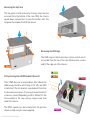
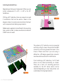
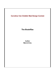
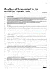
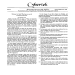
Page
2.................
3.................
4.................
5.................
6.................
7.................
Index, Foreword
Product Overview
Preparation for Assembly
Installing the Motherboard
Installing the Hard Drives
Replacing the HDD Cage and Top Panel
Foreword
Thank you for your purchase of this Streacom product, every care has been taken to
ensure that it meets with the high standards that we have set for ourselves.
Should you have any questions that are not covered in this user guide, support can be
offered via email through our website at www.streacom.com
We sincerely hope that you enjoy using our product!
P2 - INDEX
Specification
Aluminum
Silver / Black - sandblast finish
Mini ITX
1 x 3.5" + 1 x 2.5" or 3 x 2.5" (depending on components installed)
None
1 x 40x40x10mm or 1 x 60x60x10mm fan (not Included)
197 × 197 × 77mm (L×W×H) + 3mm feet
NanoPSU & external DC adapter (not included)
Streacom IRRC receiver & remote (not included)
1.6KG
Chassis Material
Available Colours
Motherboard Compatibility
HDD Drive Support
ODD Drive Support
Cooling Method
Dimensions
Power Supply Support
IR Solution
Net Weight
2
1
3
4
5
6
7
8
9
10
Key Features
1...... IR Receiver Window
2...... Top Panel
3...... Power LED
4...... Power Button
5...... 40 or 60mm Fan Bracket (Fan not Included)
6...... IO Shield Opening
7...... Power Button PCB
8...... DC Power Jack Hole
9...... IR Receiver Mounting (IRRC Not Included)
10.... HDD Mounting Cage
OVERVIEW - P3
Removing the Top Panel
The top panel is held in place by 2 long screws that are
accessed from the bottom of the case. With the chassis
upside down, remove the 2 screws from either side. The
top panel can now be lifted off the chassis.
Removing the HDD Cage
M3 x 5
The HDD cage is held in place by 6 screws, which are all
accessible from the top of the case. Remove all 6 screws
and lift the cage out of the chassis.
5 x 10
Fitting Cooling Fan & IRRC Module (Optional)
4 x 10
The F1CWS Evo can accommodate a 40 or 60mm fan
(60mm may interfere with fitting of 2.5" HD, see HDD
installation). The fan bracket is packed with the other
screws and accessories. Fit your purchased fan with 2
screws as shown (Depending on 40 or 60mm). Fit the
fan assembly to the case using a single screw from
under the chassis.
The IRRC module can be installed into the position
shown (in red) using 2 screws supplied.
P4 - PREPARING FOR ASSEMBLY
M3 x 5
M3 x 5
Installing the Motherboard
Locate the I/O shield that is supplied with your
motherboard and firmly push it in place. Ensure that it
fully clips in place otherwise the motherboard will be
difficult to fit.
The motherboard should be prepared ready for
installation by fitting CPU, cooler and RAM.
M3 x 4
Carefully lower the motherboard into the chassis, with
the I/O port side leading so that the ports align with the
I/O shield holes and can fit correctly.
When the motherboard is correctly in position, fix it to the
chassis stand-offs using the screws provided. Ensure
that all the holes correctly align before fully tightening
the screws.
Connect NanoPSU & Other Cables
With the motherboard in place, you can now connect the
PSU and any other internal connectors such as the power
button switch. You should also connect the SATA cables in
perpetration for installing the hard drives.
INSTALLING THE MOTHERBOARD - P5
Installing the Hard Drives
Depending on the type of components fitted, you can
install a maximum of 1 x 3.5" + 1 x 2.5" or 3 x 2.5"
hard drives.
If fitting a 3.5" hard drive, there are a 4 positions and
2 orientations that can be used as shown in the
diagram. Select a location and orientation that best
suits component and cabling requirements.
6#32
Rubber pads supplied can be affixed to the mounting
holes used in order to reduce mechanical vibration
(if SSD’s are not used).
The primary 2.5" hard drive can be mounted
vertically using 2 screws. Ensure that the HDD
connectors are facing toward the back of the
chassis. Please note that if you are using a
60mm fan, a 90 degree power/sata connector
must be used to avoid conflict with the fan.
M3 x 5
P6 - FITTING THE HARD DRIVES
If not installing a 3.5" hard drive, 2 x 2.5" hard
drives can be fitted horizontally as shown.
There are a total of 3 mounting positions
available for the 2.5" drives which can be
selected depending on how many drives are
used and positioning requirements.
Replace the HDD Cage
M3 x 5
With the hard drives fitted, the cage can now be
replaced into the chassis. Carefully lower the
assembly ensuring cables are routed correctly,
connected and that there is no component conflict.
The HDD cage should be secured to the chassis
using 8 screws in total, 6 at the top and 2 from
underneath. Note that the 2 screw underneath fix to
the 2.5" hard drive, so if no 2.5" drive is installed,
these screws can be ignored.
Replace the Top Panel
With all the components installed, all that remains
is to replace the top panel and secure it in place with
the 2 long screws from underneath the chassis.
When replacing the top panel, ensure the correct
orientation as the 2 long securing screws should
match up with the nuts in the top panel.
REPLACING THE HDD CAGE AND TOP PANEL - P7
www.streacom.com
V1.13.06