1
Sun StorEdge™
Enterprise Storage Manager 1.0
Topology Reporter Administration
and Operations Guide
Sun Microsystems, Inc.
4150 Network Circle
Santa Clara, CA 95054 U.S.A.
650-960-1300
Part No. 816-4293-10
July 2002, Revision A
Send comments about this document to: docfeedback@sun.com
Copyright 2002 Sun Microsystems, Inc., 4150 Network Circle, Santa Clara, California 95054, U.S.A. All rights reserved.
Sun Microsystems, Inc. has intellectual property rights relating to technology embodied in the product that is described in this document. In
particular, and without limitation, these intellectual property rights may include one or more of the U.S. patents listed at
http://www.sun.com/patents and one or more additional patents or pending patent applications in the U.S. and in other countries.
This document and the product to which it pertains are distributed under licenses restricting their use, copying, distribution, and
decompilation. No part of the product or of this document may be reproduced in any form by any means without prior written authorization of
Sun and its licensors, if any.
Third-party software, including font technology, is copyrighted and licensed from Sun suppliers.
Parts of the product may be derived from Berkeley BSD systems, licensed from the University of California. UNIX is a registered trademark in
the U.S. and in other countries, exclusively licensed through X/Open Company, Ltd.
Sun, Sun Microsystems, the Sun logo, AnswerBook2, docs.sun.com, Sun StorEdge, iPlanet, Sun Fire, Ultra, Java, and Solaris are trademarks or
registered trademarks of Sun Microsystems, Inc. in the U.S. and in other countries.
All SPARC trademarks are used under license and are trademarks or registered trademarks of SPARC International, Inc. in the U.S. and in other
countries. Products bearing SPARC trademarks are based upon an architecture developed by Sun Microsystems, Inc.
The OPEN LOOK and Sun™ Graphical User Interface was developed by Sun Microsystems, Inc. for its users and licensees. Sun acknowledges
the pioneering efforts of Xerox in researching and developing the concept of visual or graphical user interfaces for the computer industry. Sun
holds a non-exclusive license from Xerox to the Xerox Graphical User Interface, which license also covers Sun’s licensees who implement OPEN
LOOK GUIs and otherwise comply with Sun’s written license agreements.
Netscape is a trademark or registered trademark of Netscape Communications Corporation in the United States and other countries.
Use, duplication, or disclosure by the U.S. Government is subject to restrictions set forth in the Sun Microsystems, Inc. license agreements and as
provided in DFARS 227.7202-1(a) and 227.7202-3(a) (1995), DFARS 252.227-7013(c)(1)(ii) (Oct. 1998), FAR 12.212(a) (1995), FAR 52.227-19, or FAR
52.227-14 (ALT III), as applicable.
DOCUMENTATION IS PROVIDED "AS IS" AND ALL EXPRESS OR IMPLIED CONDITIONS, REPRESENTATIONS AND WARRANTIES,
INCLUDING ANY IMPLIED WARRANTY OF MERCHANTABILITY, FITNESS FOR A PARTICULAR PURPOSE OR NON-INFRINGEMENT,
ARE DISCLAIMED, EXCEPT TO THE EXTENT THAT SUCH DISCLAIMERS ARE HELD TO BE LEGALLY INVALID.
Copyright 2002 Sun Microsystems, Inc., 4150 Network Circle, Santa Clara, California 95054, Etats-Unis. Tous droits réservés.
Sun Microsystems, Inc. a les droits de propriété intellectuels relatants à la technologie incorporée dans le produit qui est décrit dans ce
document. En particulier, et sans la limitation, ces droits de propriété intellectuels peuvent inclure un ou plus des brevets américains énumérés à
http://www.sun.com/patents et un ou les brevets plus supplémentaires ou les applications de brevet en attente dans les Etats-Unis et dans les
autres pays.
Ce produit ou document est protégé par un copyright et distribué avec des licences qui en restreignent l’utilisation, la copie, la distribution, et la
décompilation. Aucune partie de ce produit ou document ne peut être reproduite sous aucune forme, parquelque moyen que ce soit, sans
l’autorisation préalable et écrite de Sun et de ses bailleurs de licence, s’il y ena.ls
Le logiciel détenu par des tiers, et qui comprend la technologie relative aux polices de caractères, est protégé par un copyright et licencié par des
fournisseurs de Sun.
Des parties de ce produit pourront être dérivées des systèmes Berkeley BSD licenciés par l’Université de Californie. UNIX est une marque
déposée aux Etats-Unis et dans d’autres pays et licenciée exclusivement par X/Open Company, Ltd.
Sun, Sun Microsystems, le logo Sun, AnswerBook2, docs.sun.com, Sun StorEdge, Sun StorEdge, iPlanet, Sun Fire, Ultra, Java, et Solaris sont des
marques de fabrique ou des marques déposées de Sun Microsystems, Inc. aux Etats-Unis et dans d’autres pays.
Toutes les marques SPARC sont utilisées sous licence et sont des marques de fabrique ou des marques déposées de SPARC International, Inc.
aux Etats-Unis et dans d’autres pays. Les produits protant les marques SPARC sont basés sur une architecture développée par Sun
Microsystems, Inc
L’interface d’utilisation graphique OPEN LOOK et Sun™ a été développée par Sun Microsystems, Inc. pour ses utilisateurs et licenciés. Sun
reconnaît les efforts de pionniers de Xerox pour la recherche et le développment du concept des interfaces d’utilisation visuelle ou graphique
pour l’industrie de l’informatique. Sun détient une license non exclusive do Xerox sur l’interface d’utilisation graphique Xerox, cette licence
couvrant également les licenciées de Sun qui mettent en place l’interface d ’utilisation graphique OPEN LOOK et qui en outre se conforment aux
licences écrites de Sun.
Netscape est une marque de Netscape Communications Corporation aux Etats-Unis et dans d'autres pays.
LA DOCUMENTATION EST FOURNIE "EN L’ÉTAT" ET TOUTES AUTRES CONDITIONS, DECLARATIONS ET GARANTIES EXPRESSES
OU TACITES SONT FORMELLEMENT EXCLUES, DANS LA MESURE AUTORISEE PAR LA LOI APPLICABLE, Y COMPRIS NOTAMMENT
TOUTE GARANTIE IMPLICITE RELATIVE A LA QUALITE MARCHANDE, A L’APTITUDE A UNE UTILISATION PARTICULIERE OU A
L’ABSENCE DE CONTREFAÇON.
Please
Recycle
Contents
Preface
1.
xv
Introduction to the Topology Reporter
What is the Topology Reporter?
Discovery
1
2
2
Notification Services
3
Launching Related Applications
4
Management and Agent Station Host Machines
Management Station
Agent Station
Log Files
5
5
6
6
Getting Started
7
Starting and Stopping the Software
Hard and Nameserver Zones
8
9
A Hard and Nameserver Zone Sharing the Same Name
Nameserver Zones Sharing the Same Name
2.
Using the Web-browser User Interface
Logging into the Web Browser
Browser User Interface
10
11
13
14
15
iii
Navigation Tips
15
Items Common to Each Page
17
Search For Drop-down Menu
▼
To Search for Assets
Discover Button
▼
19
Status Page
19
Assets Page
19
18
19
21
To Show Details about Alarms by Severity Level:
Topology Page
Health Tab
18
18
To Show Details about an Asset
Alarms Page
▼
17
To Sort Items in the Summary Table
Login Page
▼
17
To Update the Asset and Alarm Information
Summary Tables
▼
17
21
21
21
Administration Page
22
The Show Paths Button
22
Setting the Discovery Polling Interval
23
Coordinating the Discovery Polling Interval and Alarm Expiration
Threshold 23
▼
To Set the Discovery Polling Interval
SAN and DAS Changes and Discovery
▼
23
24
To Perform a Manual Discovery After a Change to Your SAN or DAS
Configuration 24
Viewing Your SAN or DAS Environment (Topology Tab)
If The Topology Page Displays An Error
iv
25
27
▼
To Set the Display
27
▼
To Show the Topology Graph or Device Details
Topology Reporter Administration and Operations Guide July 2002
29
▼
To Show Host-to-Storage Device Paths
▼
To View Zone Details
▼
To Display a Fabric's Zone
▼
To Show the DAS Inventory
Administering Users
29
30
30
31
32
Before You Add a User
33
▼
To Add a User
33
▼
To Modify a User’s Role
▼
To Delete a User
▼
To Display Information About Users
33
34
34
If An Admin User Password is Lost or Forgotten
▼
35
To Erase User Login Information from the Data Base
Managing User Email Notification
35
36
▼
To Create a User Email Notification Profile
37
▼
To Modify a User Notification Profile
▼
To Delete a User Notification Profile
▼
To Add a Contact Email Address for the admin User
39
Administering Email Servers and Network Host Notification
40
38
38
▼
To Enable and Manage SMTP Email Notification
▼
To Enable SNMP Notification
▼
To Add SNMP Notification
▼
To Modify SNMP Notification Attributes
▼
To Delete an SNMP Notification Host
Managing Applications
41
41
42
43
44
45
Using the Configuration Service for Sun StorEdge T3 and T3+ Arrays
46
▼
To Add the Sun Storage Automated Diagnostic Environment Software
Application 46
▼
To Select an Application for Managing Sun StorEdge T3 and T3+
Arrays 47
Contents
v
Managing Alarms
48
Alarm Severity Levels
48
▼
To Display Alarm Information
▼
To Set the Alarm Expiration Time and Threshold
▼
To Delete Alarms
52
To Show Asset Details
52
Searching for Assets
Host Machines
50
51
Viewing and Managing Assets
▼
49
54
54
▼
To View More Detail About a Host Machine
▼
To View More Detail About Host Machine HBA Connectivity
▼
To View the Paths Between the Host Machine and Its Storage Devices
▼
To Remove a Host
Switches
54
57
58
▼
To View More Detail About a Switch
▼
To View Switch Ports
▼
To Launch a Software Application To Manage a Switch
▼
To Remove a Switch From the Software
58
59
Managing Switch Credentials
vi
60
60
61
Finding the Switch IP Address, User Name, and Password
▼
To Add Switch Credentials
▼
To Modify Switch Credentials
▼
To Delete Switch Credentials
Storage
55
61
62
62
63
64
▼
To View More Detail About a Storage Device
▼
To View the Connection Path of the Storage Device in the SAN or DAS
Environment 65
▼
To View Storage Device Port Connections
▼
To View Storage Device LUNs
66
Topology Reporter Administration and Operations Guide July 2002
66
64
56
▼
To Launch a Software Application to Manage a Storage Device
▼
To Remove a Storage Device from the Software
Host Bus Adapters
67
67
68
▼
To View More Detail About an HBA
68
▼
To View HBA Path and Port Connections
69
Launching the Storage Automated Diagnostic Environment Software (Health
Tab) 70
▼
3.
To Launch the Sun Storage Automated Diagnostic Environment
Software 70
The sstr Command
71
Command Syntax and Usage Summary
72
▼
To Display a List of Subcommands
▼
To Display a Usage Summary of the Subcommands
Short and Long Option Names
sstr Subcommand Tables
Administering Users
73
73
83
84
sstr modify-user
85
sstr remove-user
85
sstr users
72
83
Before You Add a User
sstr add-user
72
85
Managing User Email Notification
sstr email-notifications
86
87
sstr create-email-notification
sstr email-notification
88
sstr delete-email-notification
Administering SNMP Trap Notification
sstr snmp-notifications
87
89
90
91
sstr create-snmp-notification
91
Contents
vii
92
sstr snmp-notification
sstr delete-snmp-notification
Managing Applications
93
93
sstr applications
sstr application
Managing Alarms
94
sstr alarms
94
93
94
sstr alarm
94
sstr delete-alarm
Viewing Asset Status and Topology
95
96
sstr assets
96
sstr fabrics
96
sstr fabric
sstr das
92
97
Managing Host Machines
sstr hosts
sstr host
sstr paths
99
99
99
sstr remove-host
Managing Switches
sstr switches
sstr switch
98
100
101
102
102
102
sstr switch-ports
103
sstr port-connections
103
sstr remove-switch
Managing Switch Credentials (IP Addresses and User Login)
sstr credentials
104
sstr add-credential
viii
105
Topology Reporter Administration and Operations Guide July 2002
104
105
sstr credential
105
sstr remove-credential
Managing Storage
106
sstr storage-list
sstr storage
107
107
sstr storage-luns
108
108
sstr storage-ports
108
sstr remove-storage
Managing Host Bus Adapters
sstr hbas
sstr hba
109
109
109
sstr hba-ports
109
Managing Discovery
111
sstr discover
111
SAN and DAS Changes and Discovery
▼
111
To Perform a Manual Discovery After a Change to Your SAN or DAS
Configuration 111
Showing Properties
113
sstr show-properties
Setting Software Properties
113
114
Setting the Alarm Expiration Interval
115
115
sstr set-property alarm-expiration
Setting the Alarm Logging Threshold Level
116
sstr set-property logging-threshold
116
Setting the Administrator Email Contact Address
sstr set-property contact-email
Setting the Discovery Interval
116
116
117
sstr set-property discovery-interval
Specifying the SMTP Mail Server
117
117
Contents
ix
sstr set-property smtp-server
Enabling and Disabling Notification
117
118
118
sstr set-property email-notification
sstr set-property snmp-notification
118
Specifying the Sun StorEdge T3 Array Application
sstr set-property t3-application
4.
The sstr_ctl Command
118
118
119
Command Syntax and Usage Summary
120
sstr_ctl [start|stop|-s|-b|-r|-c|-p|-v] [-h|--help]
Short and Long Option Names
121
Starting and Stopping the Software
122
Configuring the Software
123
If You Configure the Software More Than Once
Default Ports for Installation
123
Where Configuration Information is Stored
▼
To Configure the Software
125
Backing Up and Restoring the Database
▼
To Back Up the Database
▼
To Restore the Database
127
Displaying Software Properties
127
126
126
Checking for Running Software Components
▼
x
124
To Check for Running Components
Topology Reporter Administration and Operations Guide July 2002
128
128
123
120
Figures
FIGURE 1-1
Hard and Nameserver Zone Naming To Avoid, Example 1 10
FIGURE 1-2
Hard and Nameserver Zone Naming To Avoid, Example 2
FIGURE 2-1
Navigation Links Example 16
FIGURE 2-2
Table Sorting Icons 18
FIGURE 2-3
Status Page
FIGURE 2-4
Example Topology Page SAN Fabric Table
FIGURE 2-5
Host Connectivity Detail Table 55
FIGURE 2-6
Attached Ports Detail Table
11
20
26
59
xi
xii
Topology Reporter Administration and Operations Guide • July 2002
Tables
TABLE 1-1
Getting Started Tasks List 7
TABLE 2-1
User Roles 32
TABLE 2-2
Alarm Severity Levels 48
TABLE 2-3
Managing and Viewing Assets 52
TABLE 3-1
sstr Subcommands Sorted By Function 74
TABLE 3-2
sstr Subcommands Sorted By Alphabetical Order 79
TABLE 4-1
sstr_ctl Subcommands
120
xiii
xiv
Topology Reporter Administration and Operations Guide • July 2002
Preface
This document describes the administration and operation of the Sun StorEdge™
Enterprise Storage Manager 1.0 Topology Reporter. The intended audience for this
document includes Sun support engineers, storage area network (SAN)
administrators, and direct-attached storage (DAS) administrators.
How This Book Is Organized
Chapter 1 describes the software and its features.
Chapter 2 describes the Web-browser user interface and how to perform related
tasks through this interface.
Chapter 3 describes the command line interface and how to perform related tasks
through this interface.
Chapter 4 describes the sstr_ctl command and database backup and restore
procedures.
xv
Using UNIX Commands
This document might not contain information on basic UNIX® commands and
procedures such as shutting down the system, booting the system, and configuring
devices.
See one or more of the following for this information:
■
■
■
Solaris Handbook for Sun Peripherals
AnswerBook2™ online documentation for the Solaris™ operating environment
Other software documentation that you received with your system
Typographic Conventions
xvi
Typeface
Meaning
Examples
AaBbCc123
The names of commands, files,
and directories; on-screen
computer output
Edit your.login file.
Use ls -a to list all files.
% You have mail.
AaBbCc123
What you type, when contrasted
with on-screen computer output
% su
Password:
AaBbCc123
Book titles, new words or terms,
words to be emphasized.
Replace command-line variables
with real names or values.
Read Chapter 6 in the User’s Guide.
These are called class options.
You must be superuser to do this.
To delete a file, type rm filename.
[ ]
In syntax, brackets indicate that
an argument is optional.
scmadm [–d sec] [–r n[:n][,n]...] [–z]
{ arg | arg}
In syntax, braces and pipes
indicate that one of the
arguments must be specified.
sndradm -R b {p | s}
\
At the end of a command line,
the backslash (\) indicates that
the command continues on the
next line.
atm90 /dev/md/rdsk/d5 \
/dev/md/rdsk/d1 atm89 \
/dev/md/rdsk/d5 /bitmaps/map2 \
ip sync
Topology Reporter Administration and Operations Guide • July 2002
Shell Prompts
Shell
Prompt
C shell
machine-name%
C shell superuser
machine-name#
Bourne shell and Korn shell
$
Bourne shell and Korn shell superuser
#
Related Documentation
Application
Title
Part Number
Man pages
sstr
sstr_ctl
N/A
Release
Sun StorEdge Enterprise Storage Manager 1.0
Topology Reporter Release Notes
816-4292
Sun StorEdge Enterprise Storage Manager 1.0
Configuration Service Release Notes
816-4296
Sun StorEdge Enterprise Storage Manager 1.0
Topology Reporter Installation Guide
816-4291
Sun StorEdge Enterprise Storage Manager 1.0
Configuration Service Installation Guide
816-4294
Sun StorEdge Network FC Switch-8 and Switch-16
Installation and Configuration Guide, Sun StorEdge
SAN 3.0 Release
816-0830
Sun StorEdge SAN 4.0 Release Installation Guide
816-4469
Sun StorEdge Enterprise Storage Manager 1.0
Configuration Service Administrator’s Guide
816-4295
Service Location Protocol Administration Guide
806-1412
Storage Automatic Diagnostic Environment User
Guide
816-3142
Installation
System administration
Diagnostic
Preface
xvii
Application
Title
Part Number
User manual
SANbox 8/16 Segmented Loop Switch Management
User’s Manual
875-3060
SANbox 8/16 Segmented Loop Fibre Channel Switch
Installer’s/ User’s Manual
875-1881
SANbox-16 Segmented Loop Fibre Channel Switch
Installer’s/ User’s Manual
875-3059
Accessing Sun Documentation Online
A broad selection of Sun system documentation is located at:
http://www.sun.com/products-n-solutions/hardware/docs
A complete set of Solaris documentation and many other titles are located at:
http://docs.sun.com
Sun Welcomes Your Comments
Sun is interested in improving its documentation and welcomes your comments and
suggestions. You can email your comments to Sun at:
docfeedback@sun.com
Please include the part number (816-4293-10) of your document in the subject line of
your email.
xviii
Topology Reporter Administration and Operations Guide • July 2002
CHAPTER
1
Introduction to the Topology
Reporter
This chapter describes the following topics:
■
“What is the Topology Reporter?” on page 2
■
“Management and Agent Station Host Machines” on page 5
■
“Log Files” on page 6
■
“Getting Started” on page 7
■
“Starting and Stopping the Software” on page 8
■
“Hard and Nameserver Zones” on page 9
The Sun StorEdge™ Enterprise Storage Manager 1.0 Topology Reporter enables you
to view and manage your storage area network (SAN) or direct-attached storage
(DAS) environment. Using a Web-browser user interface (UI) or the command-line
interface (CLI), you can:
■
View hardware assets such as hosts, host bus adapters, switches, and storage
devices, including a graphical view of your environment
■
Manage users, alarms, and assets
■
Configure user email notification and network host notification
■
Manage asset reporting (also known as discovery)
■
Launch other management software applications related to devices in your
environment
1
What is the Topology Reporter?
The topology reporter includes agent, management, and database software installed
on host machines in your environment. The agent software continuously collects
information from devices in your environment and stores the information in a
database. This database contains the information needed to build a data model of
your environment. The agent software updates the data model depending on
discovered changes in device status.
You can view and manage this information at any time by using a Web browser or
CLI. For example, you can view a graphic representing your environment and click
parts of the graphic to see details about that host machine or device.
For information on the roles of host machines, see “Management and Agent Station
Host Machines” on page 5.
Chapter 2 and Chapter 3 describe how to use the Web browser and CLI.
Discovery
Note – See also “Setting the Discovery Polling Interval” on page 23.
Discovery is the process where software agents on agent stations retrieve
information about devices in your environment. The agents report it to the
management station and the information is stored in the software’s database. You
can then view this information by using the UI or CLI at a management station.
The first discovery process occurs at system startup time after you install the
software. After shutting down and restarting your machine, the initial discovery
process begins.
When you can first view device status depends on the size of your environment. In
a small SAN or DAS environment, you might see information immediately. In larger
environments, the initial discovery might take a few minutes. Also, discovery
depends on the agents being started on agent station machines.
Automatic discovery always occurs at a set interval. The software also enables you
to:
2
■
Set an interval for the software to start discovery automatically
■
Manually start discovery in addition to automatic discovery
Topology Reporter Administration and Operations Guide • July 2002
Each page in the UI includes a Discover button. Next to the button is the date and
time of the most recent discovery. The CLI includes commands to report the most
recent discovery date and time and start discovery.
Caution – Do not click the Discover button or use the CLI to start discovery until
the initial or any previous discovery process is finished.
See the following topics for more information about discovery.
■
“Discover Button” on page 17
■
“Setting the Discovery Polling Interval” on page 23
■
“Viewing Asset Status and Topology” on page 95
■
“Managing Discovery” on page 111
Notification Services
The software uses the Simple Mail Transfer Protocol (SMTP) to send email to users
each time an alarm occurs. You can decide which alarm severity level gets reported
to the user and how often it is reported.
The software also enables you to send information to applications that are able to
receive Simple Network Management Protocol (SNMP) traps.
See “Administering Email Servers and Network Host Notification” on page 40 and
“Administering SNMP Trap Notification” on page 90.
Chapter 1
Introduction to the Topology Reporter
3
Launching Related Applications
The software enables you to launch applications related to the devices in your SAN.
These applications include:
■
Storage Automated Diagnostic Environment software
■
Sun StorEdge Configuration Service software for the Sun StorEdge T3 and T3+
storage arrays
■
Sun StorEdge 9900 Series HiCommand software for the Sun StorEdge T3 and T3+
storage arrays
■
SANsurfer Switch Manager (SUNWsmgr) software for Sun switches
■
Web servers that reside on devices such as switches, such as Brocade
Communications Systems’ WebTools
Note – You must install these launchable applications on all relevant platforms in
your environment.
4
Topology Reporter Administration and Operations Guide • July 2002
Management and Agent Station Host
Machines
Each machine is considered a station in your environment and can have a different
role:
■
Management station
■
Agent station
You can also install the software on one machine that acts as a management station
and an agent station.
Management Station
Note – Only one machine per Service Locator Protocol (SLP) scope can be a
management station. Do not install the software on more than one machine
designated as a management station per scope. The management station and agent
stations are considered to be in the same SLP scope when each machine has the same
scope setting. The Sun StorEdge Enterprise Storage Manager 1.0 Topology Reporter
Installation Guide describes configuring the SLP scope.
The management station is the machine where you can view information about and
administer your devices using the UI or CLI. You can also install the agent software
on this machine and use it as a management and agent station.
The management station runs Web server software that enables you to access the UI
through a Web browser. You can use the Web browser on the management station or
from any machine that has access to the management station.
Chapter 1
Introduction to the Topology Reporter
5
Agent Station
The agent station can be one or more machines in your environment where the
software collects information about your devices, such as hosts, host bus adapters,
switches, and storage devices. You then use the UI or CLI on the management
station to view this information. This information collection process is known as
discovery.
You must install the agent station portion of the software on each host connected to
a SAN or switch fabric (that is, switch and storage devices and their attributes). If
you install the software on some hosts but not all, you will only partially discover
information.
Log Files
Over time, the /var/opt/SUNWnsm/cre/cre_log and
/opt/SUNWnsm/util/tomcat/logs/catalina.out files can become large. Make
sure that you check these files occasionally so that they do not consume more disk
space than desired.
The software logs information to the following log files:
■
/var/sadm/install/logs/SUNWnsm.log
This log contains error or informational messages.
■
/var/adm/messages
This log contains general system error or informational messages.
■
/var/opt/SUNWnsm/pgsql/nsmdb.log
This log contains warnings and error messages from the database.
■
/var/opt/SUNWnsm/cre/cre_log
This log contains messages from the Container Runtime Environment.
■
/var/opt/SUNWnsm/tomcat/eventtranslator.log
This log contains messages from software about events that have occurred.
■
/opt/SUNWnsm/util/tomcat/logs/catalina.out
This log contains messages from the software about any Java servlets used in the
application and any errors associated with the event translator SLP registration.
6
Topology Reporter Administration and Operations Guide • July 2002
Getting Started
After you start the software and log in through a Web browser, you can perform the
following tasks to get started. (See Chapter 3 for command-line interface equivalents
for these tasks.)
TABLE 1-1
Getting Started Tasks List
Task
Web Browser
Command-line Interface
1. Start the software
“Starting and Stopping the
Software” on page 8
“Starting and Stopping the
Software” on page 8
2. Log in through a Web browser.
“Logging into the Web Browser”
on page 14
Not applicable
3. Set the device polling interval for
the software.
“Coordinating the Discovery
Polling Interval and Alarm
Expiration Threshold” on page 23
“Setting the Discovery Interval”
on page 117
4. Configure email and SNMP
notification.
“Administering Email Servers and
Network Host Notification” on
page 40
“Specifying the SMTP Mail
Server” on page 117
“Administering SNMP Trap
Notification” on page 90
5. Set the alarm expiration interval
and alarm logging threshold.
“To Set the Alarm Expiration Time
and Threshold” on page 50
“Setting the Alarm Expiration
Interval” on page 115
“Setting the Alarm Logging
Threshold Level” on page 116
6. Add the device management
applications you can launch from
a Web browser.
“Managing Applications” on
page 45
“Managing Applications” on
page 93
7. Add users who can use the
software.
“Administering Users” on page 32
“Administering Users” on page 83
8. Set the system administrator
contact email address. The
default setting for this address is
blank.
“To Add a Contact Email Address
for the admin User” on page 39
“Setting the Administrator Email
Contact Address” on page 116
Chapter 1
Introduction to the Topology Reporter
7
Starting and Stopping the Software
Ensure that you start the software on the management station and each agent station
after you install and configure the software, as described in the Sun StorEdge
Enterprise Storage Manager 1.0 Topology Reporter Installation Guide.
● To start the software, open a terminal window and type:
# /etc/init.d/sstrd start
The software displays messages showing each software process starting.
● To stop the software, open a terminal window and type:
# /etc/init.d/sstrd stop
The software displays messages showing each software process stopping.
8
Topology Reporter Administration and Operations Guide • July 2002
Hard and Nameserver Zones
The topology reporter software can display information for hard zones and name
server zones. Some switches enable you to configure devices within your fabric or
hard zone to be part of a name server zone (also known as a soft zone).
This section describes two zone naming situations to avoid:
■
“A Hard and Nameserver Zone Sharing the Same Name” on page 10
■
“Nameserver Zones Sharing the Same Name” on page 11
Note – When creating zones, use a unique name for each zone.
Switches from Brocade Communications Systems force you to use unique names.
Switches such as the Sun StorEdge Network FC Switch-8 and Switch-16 switch and
Qlogic Corp. switches allow you to configure nonunique nameserver zone names.
Chapter 1
Introduction to the Topology Reporter
9
A Hard and Nameserver Zone Sharing the Same
Name
When you create zones using a switch management tool such as the SANsurfer
Switch Manager software, you might create hard and nameserver zones with the
same name. In this case, a hard zone might include an identically-named nameserver
zone.
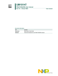
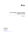
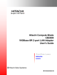
For example, FIGURE 1-1 shows:
■
One hard zone named ZONE1
■
One hard zone named ZONE2
■
One nameserver zone consisting of hard ZONE2 member devices, also named
ZONE2
When you view these identically-named zones in the topology reporter UI, the hard
zone names include the phrase (hard) as part of the name. For example,
ZONE2(hard).
Switch
Hard zone
ZONE1
Hard zone
ZONE2
Nameserver zone
ZONE2
FIGURE 1-1
10
Hard and Nameserver Zone Naming To Avoid, Example 1
Topology Reporter Administration and Operations Guide • July 2002
Nameserver Zones Sharing the Same Name
When you create zones using a switch management tool such as the SANsurfer
Switch Manager software, you might create two nameserver zones in two different
hardzones with the same name. In this case, each hard zone might include an
identically-named nameserver zone.
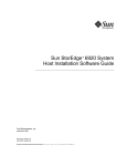
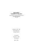
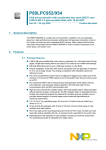
For example, FIGURE 1-2 shows:
■
One hard zone named ZONE1 with a nameserver zone named NSVR1
■
Another hard zone named ZONE2 with a nameserver zone named NSVR1
In this case, when you view the nameserver zones using the topology reporter
Web-browser UI or CLI, only one nameserver zone named NSVR1 is shown or
reported and contains the port members of both nameserver zones. (Hard zone
names include the phrase (hard) as part of the name. For example, ZONE2(hard).)
Switch
Hard zone
ZONE1
Hard zone
ZONE2
Nameserver
zone
NSVR1
FIGURE 1-2
Nameserver
zone
NSVR1
Hard and Nameserver Zone Naming To Avoid, Example 2
Chapter 1
Introduction to the Topology Reporter
11
12
Topology Reporter Administration and Operations Guide • July 2002
CHAPTER
2
Using the Web-browser User
Interface
This section describes how to log into and to navigate the Web-browser user
interface (UI). The topology reporter enables you to view and manage your storage
area network (SAN) or direct-attached storage (DAS) environment through a Web
browser. You can also add and launch external applications such as the Storage
Automated Diagnostic Environment software.
This chapter includes the following topics:
■
“Logging into the Web Browser” on page 14
■
“Browser User Interface” on page 15
■
“Setting the Discovery Polling Interval” on page 23
■
“Viewing Your SAN or DAS Environment (Topology Tab)” on page 25
■
“Administering Users” on page 32
■
“Managing User Email Notification” on page 36
■
“Administering Email Servers and Network Host Notification” on page 40
■
“Managing Applications” on page 45
■
“Managing Alarms” on page 48
■
“Viewing and Managing Assets” on page 52
■
“Launching the Storage Automated Diagnostic Environment Software (Health
Tab)” on page 70
13
Logging into the Web Browser
If you have successfully installed and started the software, log in through a Web
browser.
1. Open the Netscape™ Communicator Web browser, version 4.7x.
2. Type the following URL in the URL text field:
■
For an HTTP server:
http://your-hostname:port/nsm/
where your-hostname is your machine’s hostname and port is its port number you
configured (the default is 8180).
Note – If you are concerned about password security, use the SSL HTTP URL.
■
For an SSL HTTP server:
https://your-hostname:port/nsm/
where your-hostname is your machine’s hostname and port is its port number you
configured (typically 8543).
The Login window is displayed.
3. Log in as follows:
User Name: admin
Password: none; leave blank
4. Click the Log In button to log in.
As soon as you add a user with admin mode privileges, the default admin user is
deleted. See “Administering Users” on page 32.
Note – After users are added by the admin user and users with admin mode
privileges, they can log in using a normal user name and password.
14
Topology Reporter Administration and Operations Guide • July 2002
Browser User Interface
After you log in, you can access each page of the software by clicking its labelled tab.
■
“Navigation Tips” on page 15
■
“Items Common to Each Page” on page 17
■
“Login Page” on page 19
■
“Status Page” on page 19
■
“Assets Page” on page 19
■
“Alarms Page” on page 21
■
“Topology Page” on page 21
■
“Health Tab” on page 21
■
“Administration Page” on page 22
■
“The Show Paths Button” on page 22
Note – The Administration tab and page is not accessible for users with a role of
operator or guest.
Navigation Tips
The UI enables you to show various levels of detail about your SAN or DAS
environment. Typically, you click links and buttons as on any other Web page to
navigate the software.
The software also displays the navigation path on each page to show how you
arrived at a page. This path includes clickable, underlined links so that you can
return to a certain point in your navigation instead of starting at a top level page or
tab.
For example, if you just enabled a user to receive email notification of alarms and
want to quickly add more users, you can click the More E-Mail Features link to
return to the Add User button. See FIGURE 2-1.
The alternate method is to perform the procedure from the top level, as described in
“To Create a User Email Notification Profile” on page 37.
Chapter 2
Using the Web-browser User Interface
15
Click the More E-mail Features link to quickly add another user
FIGURE 2-1
16
Navigation Links Example
Topology Reporter Administration and Operations Guide • July 2002
Items Common to Each Page
Navigation and status items that are common to each UI page are as follows:
■
“Search For Drop-down Menu” on page 17
■
“Discover Button” on page 17
■
“Summary Tables” on page 18
Search For Drop-down Menu
The Search For drop-down menu appears on each page in the UI. This menu enables
you to search for assets in your SAN or DAS environment.
▼
To Search for Assets
1. Choose one of the following from the drop-down menu:
■
Hosts
■
Switches
■
Storage
■
HBAs
If you do not select an asset, the software searches across all assets with the asset
name you specify in the text field
2. Type an asset name in the text field and click Go to search for a particular asset.
The UI opens the Assets page and displays a table summarizing the asset or assets
found.
Discover Button
Note – See “Discovery” on page 2 for information about how the software gets
status about your SAN or DAS environment.
Also, “Setting the Discovery Polling Interval” on page 23 describes the relationship
between polling intervals and alarm intervals.
The Discover button appears on each page in the UI. Next to the Discover button is
a message showing the last time the software retrieved status about the assets and
alarms in your SAN or DAS environment.
Chapter 2
Using the Web-browser User Interface
17
▼
To Update the Asset and Alarm Information
1. Click Discover.
2. Wait a few minutes for the software to update the information on the Asset and
Alarms pages.
Summary Tables
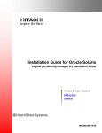
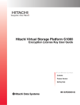
The icons shown in FIGURE 2-2 indicate that you can sort items in ascending or
descending order in summary tables found on the pages. The light-colored icon
indicates the current sort order of the selected column.
▼
To Sort Items in the Summary Table
1. Click the dark-colored icon to sort in the opposite order.
2. Click an icon in another column to sort that column.
Most tables, such as the Users summary table, include a button to select that table
item. After selecting an item, you can perform a task related to that item. For
example, see a“To Modify a User’s Role” on page 33.
Most tables also include a clickable link to see more detail about a particular device.
See FIGURE 2-2.
Indicates that this column is currently selected to sort
Clickable link to
show more information
about a device
FIGURE 2-2
18
Table Sorting Icons
Topology Reporter Administration and Operations Guide • July 2002
Login Page
The Login page includes the User Name and Password fields to enable the admin,
operator, and guest users to use the UI. (“Administering Users” on page 32 describes
user roles.) See also “Logging into the Web Browser” on page 14.
Note – If you have a user role of operator or guest and do not have access to the
software, click the System Administrator link on the Login page to send email to the
admin user. “To Add a Contact Email Address for the admin User” on page 39
describes how to add the system administrator contact email address to the link on
the Login page.
Status Page
The Status page is the default start page for the software. This page lists any current
alarms in the Alarms table, showing the number and severity of alarms. This page
also shows any installed applications that you can launch from the UI. See
FIGURE 2-3 .
Assets Page
The Assets page enables you to manage and display information about your hosts,
switches, storage, and host bus adapters (HBAs). The default Assets page shows an
Assets Summary table of all assets.
▼
To Show Details about an Asset
● Click one of the links under the Assets page tab:
■
Summary—default view for this page
■
Hosts
■
Switches
■
Storage
■
HBAs
Chapter 2
Using the Web-browser User Interface
19
FIGURE 2-3
20
Status Page
Topology Reporter Administration and Operations Guide • July 2002
Alarms Page
The Alarms page enables you to display information about any current alarms in
your SAN or DAS environment.
▼
To Show Details about Alarms by Severity
Level:
● Click one of the links under the Alarms page tab:
■
All—default view for this page
■
Down
■
Critical
■
Major
■
Minor
Topology Page
The Topology provides a top-level table view of your SAN or DAS environment.
This page also enables you to view asset details through links to the Assets page and
search for full and partial paths between a host and a storage device. See “Viewing
Your SAN or DAS Environment (Topology Tab)” on page 25.
Health Tab
When you click the Health tab, another Web browser opens to enable you to use the
Storage Automated Diagnostic Environment software. This software requires a user
name and password. See “Launching the Storage Automated Diagnostic
Environment Software (Health Tab)” on page 70. If this software is not installed, it
can be added as described in “Managing Applications” on page 45.
Chapter 2
Using the Web-browser User Interface
21
Administration Page
Note – The Administration tab and page is not accessible for users with a role of
operator or guest. “Administering Users” on page 32 describes user roles.
The Administration page enables a user with the admin role to manage:
■
Users
■
Email notification
■
Applications
■
Discovery intervals
■
Switch credentials
The Show Paths Button
The Show Paths button or drop-down menu selection is available from many
topology reporter pages. For example, the button is available from the Host and
Storage Assets pages and HBA port details page. Perform the following procedure to
view the connection path of the device in your SAN or DAS environment.
1. Click the Show Paths button or select Show Paths from the More Actions
drop-down menu.
2. Perform one of the following:
■
Click the option button and type a host name in the Host Name text field. (The
name might already be in this field.)
■
Click the option button in the table to select one of the hosts.
3. Click Next.
4. Perform one of the following:
■
Click the option button and type device name in the Storage Device name text
field. (The name might already be in this field.)
■
Click the option button in the table to select one of the devices.
5. Click Finish.
The Show Paths results page displays all existing paths between the selected host
and storage device. The SAN Paths graphic might span multiple fabrics and displays
both full and partial paths. A DAS Path graphic appears only if the host and storage
device are directly connected.
22
Topology Reporter Administration and Operations Guide • July 2002
Setting the Discovery Polling Interval
The Administration page enables the admin user to set the discovery polling
interval. Once set, this polling interval determines how often the software retrieves
information and status about devices in your SAN or DAS environment. You can set
the interval in minutes. Depending on your environment size, you can have the
software poll devices more or less frequently.
In a small SAN or DAS environment where the device configuration is stable and
device state does not change very often, you might set the polling interval to 15
minutes.
In an environment where device configuration is less stable or in a large SAN
environment where the device configuration is complex, you might set the polling
interval to a longer time, perhaps 30 minutes.
Coordinating the Discovery Polling Interval and
Alarm Expiration Threshold
You might need to coordinate the polling interval time and the alarm expiration
threshold. For example, if you set the polling interval at 10 minutes and alarm
expiration threshold at 5 minutes, it is possible that alarms might have occurred and
expired (that is, not been reported to the software). You would not see alarms in the
UI but they would have occurred.
Note – See “To Set the Alarm Expiration Time and Threshold” on page 50.
▼
To Set the Discovery Polling Interval
1. Click the Administration tab to display the Administration page.
2. Scroll down to the Miscellaneous region.
3. Enter a number in the Polling Interval text field.
4. Click Save.
Chapter 2
Using the Web-browser User Interface
23
SAN and DAS Changes and Discovery
If you add or delete assets like hosts, switches, HBAs, and storage in your
environment, you can perform a manual discovery to ensure that the new asset is
reporting its status to the software.
▼
To Perform a Manual Discovery After a Change
to Your SAN or DAS Configuration
1. Change, add, or delete an asset.
2. Wait five to seven minutes.
Waiting a few minutes gives the operating environment a chance to register changes
to the SAN or DAS environment. This discovery takes a few minutes, depending on
the size of your SAN or DAS environment.
3. Manually perform a discovery.
a. If you have not done so already, log into the software using the Netscape
Communicator v4.7x Web browser.
b. Click the Assets tab.
c. Click the Discover button.
The asset information is displayed on the Assets page.
24
Topology Reporter Administration and Operations Guide • July 2002
Viewing Your SAN or DAS Environment
(Topology Tab)
Available from the Topology tab, the Topology page enables you to view your SAN
or DAS environment. This page enables you to display up to five topology views:
■
Direct-attached storage (DAS) shows a table with clickable links for the host and
its attached storage device.
■
Storage area network (SAN) shows a table of fabrics in the SAN. The table
includes clickable links for the Fabric Name, Switches, and Zones.
■
Show Paths button shows SAN and DAS paths between the hosts and storage
devices.
■
Fabric Graph shows a graphic representation of your SAN when you click a
Fabric Name in the fabric table.
■
Zone Details shows a summary table when you click a Zones link in the fabric
table. This table includes clickable links in the Device column and for the fabric in
a link above the table.
The default view is a summary table view of the SAN fabric. See FIGURE 2-4.
This section describe procedures for the following:
■
“To Show the Topology Graph or Device Details” on page 29
■
“To Show Host-to-Storage Device Paths” on page 29
■
“To View Zone Details” on page 30
■
“To Display a Fabric's Zone” on page 30
■
“To Show the DAS Inventory” on page 31
See also:
■
“Hard and Nameserver Zones” on page 9
■
“If The Topology Page Displays An Error” on page 27
■
“SAN and DAS Changes and Discovery” on page 24
Chapter 2
Using the Web-browser User Interface
25
FIGURE 2-4
26
Example Topology Page SAN Fabric Table
Topology Reporter Administration and Operations Guide • July 2002
If The Topology Page Displays An Error
If the Web browser displays an error on the Topology page such as following
message, set the display as described:
Topology images are not available
▼
To Set the Display
1. From the machine where you are trying to display the topology graphics, type the
following:
# /usr/openwin/bin/xhost + mgmt-station-hostname:0.0
Where mgmt-station-hostname is the host name of the management station machine.
This step enables the management station to access your display.
2. Log into the management station machine as the root user.
3. If the topology reporter software is running, stop it:
# /etc/init.d/sstrd stop
4. Edit the /opt/SUNWnsm/sbin/sstr.tomcat file and update the DISPLAY
variable to the host name where you executed the xhost command in Step 1.
Change:
# Set display
DISPLAY=localhost:0.0
export DISPLAY
to:
# Set display
DISPLAY=UI-hostname:0.0
export DISPLAY
Where UI-hostname is the host name of the machine where you wish to display the
topology graphics.
Chapter 2
Using the Web-browser User Interface
27
5. Start the topology reporter software:
# /etc/init.d/sstrd start
Note – Once the topology reporter software has started, you can reset the xhost
settings on your machine and the DISPLAY setting on the management station. Use
the sstr_ctl -s status command to check that the topology reporter software
components are running. See “Checking for Running Software Components” on
page 128.
28
Topology Reporter Administration and Operations Guide • July 2002
▼
To Show the Topology Graph or Device Details
1. Click the Topology tab.
The Fabrics summary table is displayed.
2. Perform one of the following steps.
■
Click a link in the Fabric Name column to show the fabric graphic.
A graphic representing your environment is displayed.
■
■
■
Scroll down in the browser to see more if you have a larger environment.
Click a device name or graphic icon to display the Device Detail page for that
device.
Click a link in the Switches column to show switch device details.
The page displays device details. From this page, you can perform switch actions.
See “Switches” on page 58.
▼
To Show Host-to-Storage Device Paths
1. Click the Topology tab.
The Fabrics summary table is displayed.
2. To view device paths, click the Show Paths button.
3. Perform one of the following:
■
Click the option button and type a host name in the Host Name text field.
■
Click the option button in the table to select one of the hosts.
4. Click Next.
5. Perform one of the following:
■
Click the option button and type a storage device name in the Storage Device
Name text field.
■
Click the option button in the table to select one of the devices.
6. Click Finish.
The Show Paths page under the Topology tab is displayed. A graphic showing all
SAN and DAS paths from the host to the storage device appears on this page. The
SAN graphic also displays partial paths. View zone-level informationby selecting a
zone from the View Zones drop-down menu. The SAN Paths graphic might span
multiple fabrics and displays both full and partial paths. A DAS Path graphic
appears only if the host and storage device are directly connected.
Chapter 2
Using the Web-browser User Interface
29
▼
To View Zone Details
1. Click the Topology tab.
The Fabrics summary table is displayed.
2. Click a link in the Zones column.
The Zone Details summary table is displayed. The Zone Details summary table
shows the following:
■
Switch name
■
Switch port
■
Connected device name (click this link for device details)
■
Connected device vendor and model number
The table title includes a clickable link for the zone fabric. Click this link to show
graphical zone topology.
▼
To Display a Fabric's Zone
1. Click the fabric link in the Zone Details Summary table title to display the fabric
topology graphic for this zone.
You can also click the fabric name in the Fabric column shown on the Topology page.
See “To Show the Topology Graph or Device Details” on page 29.
2. From the View Zones pull-down menu, select one of the following:
■
View zonename Zone, where zonename is a zone name. Other zones appear grayed
out.
■
View Without Zones, which shows the entire fabric.
The zone graphic appears.
Note – See also “Hard and Nameserver Zones” on page 9.
30
Topology Reporter Administration and Operations Guide • July 2002
▼
To Show the DAS Inventory
1. Click the Topology tab.
2. Click the DAS link under the Topology tab.
The Direct Attached Storage summary table appears. Each host with
directly-attached storage is shown.
3. Click one of the following to show device details:
■
Host link in the Host column
■
Storage device link in the Storage column
4. Click the Show Paths button to show details about the connection paths between
a host and its storage.
See “The Show Paths Button” on page 22.
Chapter 2
Using the Web-browser User Interface
31
Administering Users
The following sections describe how to administer users through the Administration
page. As the admin user, you can add, modify, and delete users that you authorize
to use the software. Once added, a user can log into the software using his or her
user name and password. The user role determines user privileges. TABLE 2-1
describes user roles.
TABLE 2-1
User Roles
User Role
Description
admin
An admin user has all administration privileges. The admin user
can add, modify, and delete users, attributes, and devices in the
software.
operator
An operator user can use most of the software features except
those that add, modify, or delete users, attributes, and devices. This
user can delete alarms. The Administration page in the UI is not
available to this user.
guest
A guest has read-only privileges and can use most features of the
software except those that add, modify, or delete users, attributes,
and devices. The guest user can launch applications if the user has
login access to them. The Administration page in the UI is not
available to this user.
The topics described include the following:
32
■
“Before You Add a User” on page 33
■
“To Add a User” on page 33
■
“To Modify a User’s Role” on page 33
■
“To Delete a User” on page 34
■
“To Display Information About Users” on page 34
■
“If An Admin User Password is Lost or Forgotten” on page 35
Topology Reporter Administration and Operations Guide • July 2002
Before You Add a User
Before you add a user, consider the following:
▼
■
Add only those users that already have a user account on the management station
■
Users can use their Solaris (UNIX) passwords to log in. They can safely use these
passwords because they are encrypted before verification
■
root and bin cannot be added to or use the software
To Add a User
1. Click the Administration tab to display the Administration page.
2. Click the Users link under the Administration tab.
The Manage Users page is displayed.
3. Click the Add User button.
4. Type the user name of the user you are adding in the User Name text field.
The user name is the user’s login name for the machine where the software is
installed. The software authenticates the user against the machine’s list of users. The
software then stores the user information in the software’s data base.
5. Choose a user role from the Role drop-down menu.
See TABLE 2-1 for a user role description.
6. Click Save.
A confirmation message is displayed. The user can now log in to the software using
his or her normal user name and password.
▼
To Modify a User ’s Role
1. Click the Administration tab to display the Administration page.
2. Click the Users link under the Administration tab.
The Manage Users page is displayed.
3. Click the button in the Users table to select the user to modify.
4. Click the Modify User button.
5. Choose a user role from the Role drop-down menu.
See TABLE 2-1 for a user role description.
Chapter 2
Using the Web-browser User Interface
33
6. Click Save.
A confirmation message is displayed. The user can now log in to the software.
▼
To Delete a User
1. Click the Administration tab to display the Administration page.
2. Click the Users link under the Administration tab.
The Manage Users page is displayed.
3. Click the button in the Users table to select the user to delete.
4. Click the Delete User button.
5. Click the Delete button.
▼
To Display Information About Users
1. Click the Administration tab to display the Administration page.
2. Click the Users link under the Administration tab.
The Manage Users page is displayed. This page displays all users currently
authorized to use the software and their role.
34
Topology Reporter Administration and Operations Guide • July 2002
If An Admin User Password is Lost or Forgotten
If a user with the role of admin forgets or loses his or her password and no other
users with the admin role exist, the administrator of the management station
machine must clear the user database.
Caution – This procedure erases all user login information for the software.
▼
To Erase User Login Information from the Data
Base
1. Log into the management station as user sstr001.
# rlogin hostname sstr001
Password: sstr
Note – You changed the default password shown when you installed the software.
2. Source the database environment file to configure the database environment
variables.
Bourne or Korn shell
# . /opt/SUNWnsm/util/pgsql/nsm1/bin/postgres.env
C shell
# source /opt/SUNWnsm/util/pgsql/nsm1/bin/postgres.env
3. Access the database.
# psql
4. At the database prompt, delete the user table information and exit.
The pound sign (#) in this case does not indicate a root user Solaris prompt.
#nsm1 delete from userpo;
#nsm1 \q
Chapter 2
Using the Web-browser User Interface
35
Managing User Email Notification
Note – You must enable email notification for the software to use this feature. See
“Administering Email Servers and Network Host Notification” on page 40.
When a device alarm occurs, email is sent by the software to users designated by the
admin user. The Notification section of the Administration page enables the admin
user to manage this capability.
This section describes the procedures that enable the admin user to manage user
email notification:
36
■
“To Create a User Email Notification Profile” on page 37
■
“To Modify a User Notification Profile” on page 38
■
“To Delete a User Notification Profile” on page 38
■
“To Add a Contact Email Address for the admin User” on page 39
Topology Reporter Administration and Operations Guide • July 2002
▼
To Create a User Email Notification Profile
1. Click the Administration tab to display the Administration page.
2. Click the More E-mail Features button.
The More E-mail Features page is displayed. This page also displays a summary
table of users who receive notification of alarms.
3. Click the Add button in the Alarm Levels section.
The Add E-mail Address page is displayed.
4. Choose an alarm level from the Alarm Level drop-down menu.
The user you create receives email notification of alarms occurring at this level. For
example, select Critical to send all Critical alarms.
Tip – If you want the user to receive notification of other alarms levels, repeat all
steps in this section for each alarm level for that user.
5. Choose how the user receives notification from the Medium: drop-down menu.
You can choose to send notification through email or to a pager address.
6. Type the user email address in the E-mail Address text field.
Click the Send Test E-mail button to ensure that the email address is correct and
operating.
7. Type the minimum time between notification messages in the text field.
Choose the time interval from the drop-down menu: Minutes, Hours, or Days.
8. Choose the user’s locale from the Locale drop-down menu.
9. Click Save.
A confirmation message is displayed.
Chapter 2
Using the Web-browser User Interface
37
▼
To Modify a User Notification Profile
1. Click the Administration tab to display the Administration page.
2. Click the More E-mail Features button.
The More E-mail Features page is displayed. This page also displays a summary
table of users who receive notification of alarms.
3. Click the button in the Alarm Level table to select the user to modify.
4. Click the Modify button.
The Modify E-mail Address page is displayed. You can change the medium, email
address, notification interval, and locale.
5. Click Save.
A confirmation message is displayed.
▼
To Delete a User Notification Profile
1. Click the Administration tab to display the Administration page.
2. Click the More E-mail Features button.
The More E-mail Features page is displayed. This page also displays a summary
table of users who receive notification of alarms.
3. Click the button in the Alarm Level table to select the user to delete.
The Delete E-mail Address page is displayed and asks if you want to delete the user.
4. Click the Delete button.
A confirmation message is displayed.
38
Topology Reporter Administration and Operations Guide • July 2002
▼
To Add a Contact Email Address for the admin
User
1. Click the Administration tab to display the Administration page.
2. Scroll down the page to the Miscellaneous section.
3. Type an email address for the admin user in the Contact E-mail text field.
This email address is the address associated with the system administrator link on
the Login page (see “Login Page” on page 19).
4. Click Save.
Chapter 2
Using the Web-browser User Interface
39
Administering Email Servers and
Network Host Notification
When a device alarm occurs, email is sent by the software to users designated by the
admin user. The host machine where the alarm occurred also routes the alarm
information to a management station machine. You can then view this alarm
information on the Alarm page.
The Notification section of the Administration page enables the admin user to
manage this capability. This section describes the procedures that enable the admin
user to manage the Simple Mail Transfer Protocol (SMTP) and Simple Network
Management Protocol (SNMP) servers and notification:
40
■
“To Enable and Manage SMTP Email Notification” on page 41
■
“To Enable SNMP Notification” on page 41
■
“To Add SNMP Notification” on page 42
■
“To Modify SNMP Notification Attributes” on page 43
■
“To Delete an SNMP Notification Host” on page 44
Topology Reporter Administration and Operations Guide • July 2002
▼
To Enable and Manage SMTP Email Notification
1. Click the Administration tab to display the Administration page.
2. Select the On or Off buttons in the Notification E-mail section:
These buttons enable or disable the email notification feature. See also “Managing
User Email Notification” on page 36.
3. Click the More E-Mail Features button to access SMTP server and alarm features.
The More E-mail Features page is displayed. This page also displays a summary
table of users who receive notification of alarms.
4. Enter the IP address or host name of the SMTP server machine in the IP or Host
text field.
The host name of the machine that will manage the notification feature must be the
fully qualified host name including the domain. For example,
martha.xyzcorp.com.
5. Click Save.
A confirmation message is displayed.
▼
To Enable SNMP Notification
1. Click the Administration tab to display the Administration page.
2. Select the On or Off buttons in the Notification SNMP section:
These buttons enable or disable the SNMP alarm trap notification feature.
Chapter 2
Using the Web-browser User Interface
41
▼
To Add SNMP Notification
1. Click the Administration tab to display the Administration page.
2. Click the More SNMP Features button to access SNMP server and alarm features.
The More SNMP Features page is displayed. This page also displays a summary
table of host machines that receive SNMP alarm traps that occur in the SAN or DAS.
3. Click the Add button.
The Add SNMP Contract page is displayed.
4. Select an alarm level to trap from the Alarm Level drop-down menu.
5. Enter the IP address or host name of an SNMP host machine in the Hostname text
field.
The host name of the management station machine where SNMP traps are routed
must be the fully qualified host name including the domain. For example,
martha.xyzcorp.com.
6. Enter a port number in the Port Number text field.
The default SNMP port is 162.
7. Choose one of the following locales from the drop-down menu:
■
English
■
French
■
German
■
Japanese
8. Click Save.
A confirmation message is displayed.
42
Topology Reporter Administration and Operations Guide • July 2002
▼
To Modify SNMP Notification Attributes
1. Click the Administration tab to display the Administration page.
2. Click the More SNMP Features button to access SNMP server and alarm features.
The More SNMP Features page is displayed. This page also displays a summary
table of host machines that receive SNMP alarm traps that occur in the SAN or DAS.
3. Click the Modify button.
The Modify SNMP Contract page is displayed. You can change the SNMP host’s host
name, SNMP port, and alarm level from this page.
4. Enter the IP address or host name of an SNMP host machine in the Hostname text
field.
The host name of the management station machine where SNMP traps are routed
must be the fully qualified host name including the domain. For example,
martha.xyzcorp.com.
5. Enter a port number in the Port Number text field.
The default SNMP port is 162.
6. Choose one of the following locales from the drop-down menu:
■
English
■
French
■
German
■
Japanese
7. Click Save.
A confirmation message is displayed.
Chapter 2
Using the Web-browser User Interface
43
▼
To Delete an SNMP Notification Host
1. Click the Administration tab to display the Administration page.
2. Click the More SNMP Features button to access SNMP server and alarm features.
The More SNMP Features page is displayed. This page also displays a summary
table of host machines that receive SNMP alarm traps that occur in the SAN or DAS.
3. Choose a host machine to delete in the SNMP Notification summary table.
4. Click the Delete button.
A delete confirmation page is displayed.
5. Click the Delete button to delete the host machine from the database.
44
Topology Reporter Administration and Operations Guide • July 2002
Managing Applications
Users can launch software applications associated with devices in the software from
the Assets page. For example, you can launch the following software that helps
manage devices:
■
Sun StorEdge Enterprise Storage Manager Configuration Service software for the
Sun StorEdge T3 and T3+ storage arrays
■
Storage Automated Diagnostic Environment software
■
Sun StorEdge 9900 Series HiCommand software
This section describes the procedures that enable the admin user to add
Web-browser-based launchable applications to the UI.
■
“Using the Configuration Service for Sun StorEdge T3 and T3+ Arrays” on
page 46
■
“To Add the Sun Storage Automated Diagnostic Environment Software
Application” on page 46
■
“To Select an Application for Managing Sun StorEdge T3 and T3+ Arrays” on
page 47
See also:
■
“To Launch a Software Application To Manage a Switch” on page 60
■
“To Launch a Software Application to Manage a Storage Device” on page 67
Chapter 2
Using the Web-browser User Interface
45
Using the Configuration Service for Sun StorEdge
T3 and T3+ Arrays
You can use the configuration service software as the device management tool for
Sun StorEdge T3 and T3+ arrays. Consider the following:
■
If you have already logged into the configuration service software in a separate
Web-browser window, this separate window displays information about the
device when you click the Launch Device Manager button from the storage Assets
page.
Note – If you already have a configuration service Web-browser window open and
click the Launch Device Manager button, a new window does not open. That is,
another instance of the software is not launched.
■
If you have not logged into the configuration service software in a separate
Web-browser window, you must log in and discover the device in the launched
Web-browser window. For instance, the array must already be configured for
discovery by the configuration service or discovery fails. If the device is already
configured for discovery, log in and the device is discovered automatically.
See the configuration service documentation listed in “Related Documentation” on
page xvii.
▼
To Add the Sun Storage Automated Diagnostic
Environment Software Application
1. Click the Administration tab.
2. Scroll down the page to the Applications section.
The Applications section shows the Applications area.
3. Type the Storage Automated Diagnostic Environment software application
uniform resource locator (URL) address in the SADE text field.
This application launches when you click the Launch Health Application button on
the Health page.
4. Click Save.
46
Topology Reporter Administration and Operations Guide • July 2002
▼
To Select an Application for Managing Sun
StorEdge T3 and T3+ Arrays
1. Click the Administration tab.
2. Scroll down the page to the Applications section.
The Applications section shows the T3 Management drop-down menu.
3. Choose an application for managing Sun StorEdge T3 and T3+ arrays from the T3
Management drop-down menu:
■
SCCS—configuration service
■
HiCommand—Sun StorEdge 9900 Series HiCommand software
4. Type the related application's uniform resource locator (URL) address in the
HiCommand or SSCS text field.
This application launches when you click the Launch Device Manager button
associated with storage devices from the storage Assets page.
See “Using the Configuration Service for Sun StorEdge T3 and T3+ Arrays” on
page 46 and “To Launch a Software Application to Manage a Storage Device” on
page 67.
5. Click Save.
Chapter 2
Using the Web-browser User Interface
47
Managing Alarms
This section describes the procedures that enable the admin user to view and
manage alarms. The Status page is the default page shown after you log in and it
shows an Alarms summary table.
■
“Alarm Severity Levels” on page 48
■
“To Display Alarm Information” on page 49
■
“To Set the Alarm Expiration Time and Threshold” on page 50
■
“To Delete Alarms” on page 51
Alarm Severity Levels
The software reports alarms occurring at four alarm levels shown in TABLE 2-2.
TABLE 2-2
48
Alarm Severity Levels
Alarm Severity Level
Description
Down
A fatal nonrecoverable error has occurred. For example, this error
level occurs when a storage array is offline or unreachable.
Critical
A serious error has occurred. For example, this alarm type might
occur if one or more subsystems fail. This alarm type requires your
immediate attention.
Major
A serious error has occurred. For example, this alarm type might
occur if one subsystem has failed. This alarm type requires your
immediate attention.
Minor
An error or user action has occurred that requires your attention. For
example, the admin user might have removed an asset. However, the
error does not require your immediate attention.
Topology Reporter Administration and Operations Guide • July 2002
▼
To Display Alarm Information
1. Click the Alarms tab.
The Alarms page is displayed. The default view in the Alarms table shows all
alarms.
2. Perform one of the following:
■
■
Choose one of the following links below the Alarms tab to view alarms of that
severity level:
■
All
■
Down
■
Critical
■
Major
■
Minor
Click the link in the Description column to view details about that alarm.
The page shows the alarm details. See TABLE 2-2 for a description of alarm severity
levels.
3. If the number of alarms requires more than one page to display, scroll down the
page and select the next page to display.
If a large number of alarms exist, it might take a few minutes to display them all.
4. To return to the alarm summary table, click the All link.
Chapter 2
Using the Web-browser User Interface
49
▼
To Set the Alarm Expiration Time and
Threshold
Note – See “Coordinating the Discovery Polling Interval and Alarm Expiration
Threshold” on page 23.
1. Click the Administration tab.
2. Set the alarm expiration time in the Alarms section:
a. Type a number in the Expiration Time text field.
b. Choose a time interval from the drop-down menu.
Choose Minutes, Hours, or Days. This option sets how long the alarm remains
active, is reported on the Alarms page, and then is closed by the software.
3. Choose an alarm severity level from the Log Threshold drop-down menu in the
Logging section.
Note – All topology reporter alarm events are at the Minor level.
The level that you choose enables the software to log alarms of that level and below
to the log file. For example, select Critical to see all Critical, Major, and Minor
alarms.
4. Click Save.
50
Topology Reporter Administration and Operations Guide • July 2002
▼
To Delete Alarms
1. Click the Alarms tab.
The Alarms page is displayed. The default view in the Alarms table shows all
alarms.
2. Select one or more alarms in the All Alarms table by clicking the check box to the
left of the Alarm Severity column.
3. Click the Delete Alarms button.
A confirmation page is displayed.
4. Click the Delete button.
5. To delete alarms by alarm severity level, choose one of the following links below
the Alarms tab to view alarms of that severity level:
■
Down
■
Critical
■
Major
■
Minor
See TABLE 2-2 for a description of alarm severity levels.
6. Repeat Step 2 to Step 5.
Chapter 2
Using the Web-browser User Interface
51
Viewing and Managing Assets
This section describes the procedures that enable the admin user to view and
manage assets such as hosts, switches, storage, and host bus adapters (HBAs). The
Assets page initially shows an Assets summary table that provides a top-level view
of all devices in your SAN or DAS environment.
See “Summary Tables” on page 18 for a description of summary tables.
▼
To Show Asset Details
● Click one of the links under the Assets page tab:
■
All—default view for this page
■
Hosts
■
Switches
■
Storage
■
HBAs
A summary table for the selected asset is displayed.
TABLE 2-3 list the assets and sections that describe the details.
TABLE 2-3
Managing and Viewing Assets
Asset
See This Section
All
“Searching for Assets” on page 54
Host machine
“Host Machines” on page 54
“To View More Detail About a Host Machine” on page 54
“To View More Detail About Host Machine HBA Connectivity” on page 55
“To View the Paths Between the Host Machine and Its Storage Devices” on
page 56
Switches
“Switches” on page 58
“To View More Detail About a Switch” on page 58
“To View Switch Ports” on page 59
“To Launch a Software Application To Manage a Switch” on page 60
“To Remove a Switch From the Software” on page 60
“Managing Switch Credentials” on page 61
52
Topology Reporter Administration and Operations Guide • July 2002
TABLE 2-3
Managing and Viewing Assets (Continued)
Asset
See This Section
Storage
“Storage” on page 64
“To View More Detail About a Storage Device” on page 64
“To View the Connection Path of the Storage Device in the SAN or DAS
Environment” on page 65
“To View Storage Device Port Connections” on page 66
“To View Storage Device LUNs” on page 66
“To Launch a Software Application to Manage a Storage Device” on
page 67
“To Remove a Storage Device from the Software” on page 67
HBAs
“Host Bus Adapters” on page 68
“To View More Detail About an HBA” on page 68
“To View HBA Path and Port Connections” on page 69
Chapter 2
Using the Web-browser User Interface
53
Searching for Assets
To search for assets in your environment, see “Search For Drop-down Menu” on
page 17.
Host Machines
This section describes how to view and manage hosts machines in your SAN or DAS
environment.
▼
To View More Detail About a Host Machine
1. Click the Assets tab.
The Assets page is displayed.
2. Click the Hosts link under the Assets tab.
A Hosts summary table is displayed. This table includes links for the host machine
and vendor name.
3. Click a host machine link in the Name column.
The Device Detail page is displayed. The detail includes:
■
Vendor and model name
■
Operating environment revision level
■
Clickable links to the host machine’s HBAs
■
Annotation text field that is used to include additional information or messages
about the device
■
Drop-down Host Actions menu with Remove, View Connectivity, and Show Paths
as the choices
4. To associate a comment with an asset, type message text in the Annotation text
field.
5. Click Save.
A confirmation page is displayed.
54
Topology Reporter Administration and Operations Guide • July 2002
▼
To View More Detail About Host Machine HBA
Connectivity
1. Click the Assets tab.
The Assets page is displayed.
2. Click the Hosts link under the Assets tab.
A Hosts summary table is displayed. This table includes links for the host machine
and vendor name.
3. Click the option button to select the host machine.
4. Click the View Connectivity button.
The Connectivity Detail page is displayed. This page shows HBA details for the
HBAs installed in this host (FIGURE 2-5).
Host1
FIGURE 2-5
Host Connectivity Detail Table
Chapter 2
Using the Web-browser User Interface
55
▼
To View the Paths Between the Host Machine
and Its Storage Devices
1. Click the Assets tab.
The Assets page is displayed.
2. Click the Hosts link under the Assets tab.
A Hosts summary table is displayed. This table includes links for the host machine
and vendor name.
3. Click a host machine link in the Name column.
The Device Detail page is displayed.
4. Choose Show Paths from the Host Actions drop-down menu.
The Show Paths page is displayed.
5. Perform one of the following:
■
Click the option button and type a host name in the Host Name text field.
■
Click the option button in the table to select one of the hosts.
6. Click Next.
7. Perform one of the following:
■
Click the option button and type a storage device name in the Storage Device
Name text field.
■
Click the option button in the table to select one of the devices.
8. Click Finish.
The Show Paths page is displayed. A graphic showing all SAN and DAS paths from
the host to the storage device appears on this page. The SAN graphic also displays
partial paths. View zone-level informationby selecting a zone from the View Zones
drop-down menu. The SAN Paths graphic might span multiple fabrics and displays
both full and partial paths. A DAS Path graphic appears only if the host and storage
device are directly connected.
See also “Viewing Your SAN or DAS Environment (Topology Tab)” on page 25.
56
Topology Reporter Administration and Operations Guide • July 2002
▼
To Remove a Host
1. Click the Assets tab.
The Assets page is displayed.
2. Click the Hosts link under the Assets tab.
A Hosts summary table is displayed. This table includes links for the host machine
and vendor name.
3. Click the option button to select the host machine.
4. Click the Remove button to remove the host from the software.
Chapter 2
Using the Web-browser User Interface
57
Switches
This section describes how to view and manage switches in your SAN or DAS
environment. It also describes how to launch a software application in another
Web-browser to manage a switch.
▼
To View More Detail About a Switch
1. Click the Assets tab.
The Assets page is displayed.
2. Click the Switches link under the Assets tab.
A Switches summary table is displayed. This table includes switch name links, IP
address, World Wide Name (WWN), vendor and model name, and firmware revision
level. Also displayed are the Remove, Launch Device Manager, and Show Ports
buttons.
3. Click a switch name link in the Name column.
The Device Detail page is displayed. The detail includes:
■
IP address and WWN
■
Vendor or model name
■
Firmware revision level
■
Domain ID
■
Annotation text field that is used to include additional information or messages
about the device
4. To add a comment about the asset, type message text in the Annotation text field.
5. Click Save.
A confirmation page is displayed.
58
Topology Reporter Administration and Operations Guide • July 2002
▼
To View Switch Ports
1. Click the Assets tab.
The Assets page is displayed.
2. Click the Switches link under the Assets tab.
A Switches summary table is displayed. This table includes switch name links, IP
address, World Wide Name (WWN), vendor and model name, and firmware revision
level. Also displayed are the Remove, Launch Device Manager, and Show Ports
buttons.
3. Click a switch name link in the Name column.
The Device Detail page is displayed.
4. Choose Show Ports from the Switch Actions drop-down menu.
The Ports summary table is displayed.
5. Click the option button in the table to select a port.
6. Click the Show Attached Ports button.
The Attached Ports table is displayed (FIGURE 2-6).
Note that the device in the Device column is a clickable link. For example, this link
displays the HBA Device Details page. See “To View More Detail About an HBA” on
page 68.
FIGURE 2-6
Attached Ports Detail Table
Chapter 2
Using the Web-browser User Interface
59
▼
To Launch a Software Application To Manage a
Switch
1. Click the Assets tab.
The Assets page is displayed.
2. Click the Switches link under the Assets tab.
A Switches summary table is displayed.
3. Click an option button next to the device name to select that device.
4. Click the Launch Device Manager button.
The software launches the related switch management application in another Web
page. For example, the launched software for Brocade Communications Systems
switches require that you provide a user name and password to log in to the Web
server residing in the switch. For switches using the SANsurfer software, a window
opens, requiring you to enter a host name (for example, hostname:0.0) where the
application will display.
▼
To Remove a Switch From the Software
1. Click the Assets tab.
The Assets page is displayed.
2. Click the Switches link under the Assets tab.
A Switches summary table is displayed. This table includes switch name links, IP
address, World Wide Name (WWN), vendor and model name, and firmware revision
level. Also displayed are the Remove, Launch Device Manager, and Show Ports
buttons.
3. Click an option button next to the device name to select that device.
4. Click the Remove button.
A confirmation page is displayed.
5. Click the Remove button.
The switch is removed from the software database of devices in your SAN or DAS
environment.
60
Topology Reporter Administration and Operations Guide • July 2002
Managing Switch Credentials
The discovery agent of the software contacts the hardware switch for its status and
identification. The switch then requires a user name and password to access the
devices. Use these procedures to manage the IP addresses of the switch hardware
and add an authorized user so that the switch can report its status to the software.
Note – If the switch requires a user name and password to access the devices and
you have not entered this information through the browser user interface or
command-line interface, you might see error messages related to XML parsing or
other exceptions. To fix this, you need to enter the switch information into the
software.
Finding the Switch IP Address, User Name, and
Password
The typical out-of-the-box default login information for a switch is:
Username: admin
Password: password
To find the IP address, contact your system administrator or click the switch graphic
in the Topology page to see the switch IP address. The user name and password
must match the settings you entered for the switch when you used the switch’s
management tool.
Note – This step makes the software aware of switch user names and passwords
and does not change existing switch settings.
Chapter 2
Using the Web-browser User Interface
61
▼
To Add Switch Credentials
Note – These steps makes the software aware of switch user names and passwords
and does not change existing switch settings.
1. Click the Administration tab to display the Administration page.
2. Click the Out-of-band Credentials link under the Administration tab.
The Out-of-band Credentials page is displayed.
3. Click the Add button.
4. Type the required information in the related text field:
■
Address—IP address of the switch
■
User Name—The user’s login name for the switch. Typically this field is admin.
■
Password—The default is a blank password if you choose not to use one.
■
Verify Password—If you use a password, type it again.
5. Click Save.
A confirmation page is displayed.
▼
To Modify Switch Credentials
6. Click the Out-of-band Credentials link under the Administration tab.
The Out-of-band Credentials page is displayed.
7. Click the option button next to the IP Address column to select a user.
8. Click the Modify button.
9. Type the required information in the related text field:
■
User Name—The user’s login name for the switch. Typically this field is admin.
■
Password—The default is a blank password if you choose not to use one.
■
Verify Password—If you use a password, type it again.
10. Click Save.
A confirmation page is displayed.
62
Topology Reporter Administration and Operations Guide • July 2002
▼
To Delete Switch Credentials
1. Click the Administration tab to display the Administration page.
2. Click the Out-of-band Credentials link under the Administration tab.
The Out-of-band Credentials page is displayed.
3. Click the option button next to the IP Address column to select a user.
4. Click the Delete button.
A confirmation page is displayed.
5. Click the Delete button.
6. Click Save.
Chapter 2
Using the Web-browser User Interface
63
Storage
This section describes how to view and manage storage devices in your SAN or DAS
environment. It also describes how to launch a software application in another Web
browser to manage a storage device.
▼
To View More Detail About a Storage Device
1. Click the Assets tab.
The Assets page is displayed.
2. Click the Storage link under the Assets tab.
A Storage summary table is displayed. This table includes storage name links, status,
IP address (which you enter in Step 4), vendor and model name, and firmware
revision level. Also displayed are the Remove and Launch Device Manager buttons
and the More Actions drop-down menu.
3. Click a storage name link in the Name column.
The Device Detail page is displayed. The detail includes:
■
Status
■
IP address and node WWN
■
Vendor or model name
■
Firmware revision level
■
Annotation text field that is used to include additional information or messages
about the device
■
Storage Actions drop-down menu
4. Type the IP address of the device in the IP Address field.
The IP address is displayed in summary tables when you click Save.
5. To add a comment about the asset, type message text in the Annotation text field.
6. Click Save.
A confirmation page is displayed.
64
Topology Reporter Administration and Operations Guide • July 2002
▼
To View the Connection Path of the Storage
Device in the SAN or DAS Environment
1. Click the Assets tab.
The Assets page is displayed.
2. Click the Storage link under the Assets tab.
A Storage summary table is displayed.
3. Click the link in the Name column to select a device.
4. Choose Show Paths from the Storage Actions drop-down menu.
5. Perform one of the following at the displayed page:
■
Click the option button and type a host name in the Host Name text field.
■
Click the option button in the table to select one of the hosts.
6. Click Next.
7. Perform one of the following:
■
Click the option button and type a storage name in the Storage Device Name text
field.
■
Click the option button in the table to select one of the devices.
8. Click Finish.
The Show Paths page is displayed. A graphic showing all SAN and DAS paths from
the host to the storage device appears on this page. The SAN graphic also displays
partial paths. View zone-level informationby selecting a zone from the View Zones
drop-down menu. The SAN Paths graphic might span multiple fabrics and displays
both full and partial paths. A DAS Path graphic appears only if the host and storage
device are directly connected.
See also “Viewing Your SAN or DAS Environment (Topology Tab)” on page 25.
Chapter 2
Using the Web-browser User Interface
65
▼
To View Storage Device Port Connections
1. Click the Assets tab.
The Assets page is displayed.
2. Click the Storage link under the Assets tab.
A Storage summary table is displayed which shows the port WWN and node WWN.
3. Click the link in the Name column to select a device.
4. Choose Show Ports from the Storage Actions drop-down menu.
5. Click the option button in the table to select a device.
6. Click the Attached FPorts button.
The Attached Ports page is displayed, showing a Ports summary table. The table
includes the Port Type, Port WWN, Device Type, and Device columns. Note that the
device in the Device column is a clickable link. This link displays switch or other
device details table.
▼
To View Storage Device LUNs
1. Click the Assets tab.
The Assets page is displayed.
2. Click the Storage link under the Assets tab.
A Storage summary table is displayed.
3. Click the option button next to the Name column to select a device.
4. Choose Show LUNs from the More Actions drop-down menu.
The LUNs summary table is displayed.
66
Topology Reporter Administration and Operations Guide • July 2002
▼
To Launch a Software Application to Manage a
Storage Device
1. Click the Assets tab.
The Assets page is displayed.
2. Click the Storage link under the Assets tab.
A Storage summary table is displayed.
3. Click an option button next to the device name to select that device.
4. Click the Launch Device Manager button.
The software launches the related storage management application in another Web
page. For example, the launched configuration service software for Sun StorEdge T3
storage arrays requires that you provide a user name and password to log in to the
software.
See “Managing Applications” on page 45 and “Using the Configuration Service for
Sun StorEdge T3 and T3+ Arrays” on page 46.
Note – If you already have a configuration service Web-browser window open and
click the Launch Device Manager button, a new window does not open. That is,
another instance of the software is not launched.
▼
To Remove a Storage Device from the Software
1. Click the Assets tab.
The Assets page is displayed.
2. Click the Storage link under the Assets tab.
A Storage summary table is displayed.
3. Click the option button next to the Name column to select a device.
4. Click the Remove button.
A confirmation page is displayed.
5. Click the Remove button.
The storage device is removed from the software database of devices in your SAN or
DAS environment.
Chapter 2
Using the Web-browser User Interface
67
Host Bus Adapters
This section describes how to view and manage HBAs in your SAN or DAS
environment.
▼
To View More Detail About an HBA
1. Click the Assets tab.
The Assets page is displayed.
2. Click the HBAs link under the Assets tab.
An HBA summary table is displayed. This table includes device path, device name
links, host name, vendor or model name, and firmware revision level.
3. Click a device name link in the Path column.
The Device Detail page is displayed. The detail includes:
68
■
Host name of the machine where the HBA is installed
■
Device path
■
Vendor or model name
■
Firmware revision level
■
Show Ports button to view HBA port details
Topology Reporter Administration and Operations Guide • July 2002
▼
To View HBA Path and Port Connections
1. Click the Assets tab.
The Assets page is displayed.
2. Click the HBAs link under the Assets tab.
An HBA summary table is displayed. This table includes device path, device name
links, host name, vendor or model name, and firmware revision level.
3. Click the option button next to the Device Path column to select a device.
4. Click the Show Ports button.
A Ports Device Details page is displayed. The table shown includes two buttons:
■
Show Paths button
■
Show Attached Ports button
5. Click the Show Paths button.
6. Perform one of the following at the displayed page:
■
Click the option button and type a host name in the Host Name text field.
■
Click the option button in the table to select one of the hosts.
7. Click Next.
8. Perform one of the following:
■
Click the option button and type an IP address in the Storage Device IP Address
text field.
■
Click the option button in the table to select one of the devices.
9. Click Finish.
The Show Paths page under the Topology tab is displayed. A graphic showing the
path from your host to the storage device appears on this page. See “Viewing Your
SAN or DAS Environment (Topology Tab)” on page 25.
10. Perform Step 1 to Step 4.
11. Click the Show Attached Ports button.
The Attached Ports table is displayed. See FIGURE 2-6 for an example of this table.
Note that the device in the Device column is a clickable link. This link displays the
Device Details page related to the device attached to the HBA port. For example, if
the device is a switch, see “To View More Detail About a Switch” on page 58.
Chapter 2
Using the Web-browser User Interface
69
Launching the Storage Automated
Diagnostic Environment Software
(Health Tab)
When you click the Health tab, another Web browser opens to enable you to use the
Storage Automated Diagnostic Environment software. This software requires a user
name and password.
You add this application as described in “Managing Applications” on page 45.
Note – If you already have a Storage Automated Diagnostic Environment Web
browser window open and click the Launch Health Application button, a new
window does not open. That is, another instance of the software is not launched.
▼
To Launch the Sun Storage Automated
Diagnostic Environment Software
1. Click the Health tab.
2. Click the Launch Health Application button.
A new Web browser opens.
3. Enter a user name and password.
The Master Configuration window is displayed. See the Storage Automatic Diagnostic
Environment User Guide for more information.
70
Topology Reporter Administration and Operations Guide • July 2002
CHAPTER
3
The sstr Command
Note – Issue these commands from the management station.
This chapter describes the topology reporter /opt/SUNWnsm/bin/sstr command
line and options. The sstr command enables you to perform the same software
operations as you can by using the Web-browser user interface (UI). Any changes
you make by using this command are shown in the UI when you refresh or reload
the related page in your browser.
This chapter includes the following topics:
■
“Command Syntax and Usage Summary” on page 72
■
“Administering Users” on page 83
■
“Managing User Email Notification” on page 86
■
“Administering SNMP Trap Notification” on page 90
■
“Managing Applications” on page 93
■
“Managing Alarms” on page 94
■
“Viewing Asset Status and Topology” on page 95
■
“Managing Host Machines” on page 98
■
“Managing Switches” on page 101
■
“Managing Storage” on page 106
■
“Managing Host Bus Adapters” on page 109
■
“Managing Discovery” on page 111
■
“Showing Properties” on page 113
■
“Setting Software Properties” on page 114
71
Command Syntax and Usage Summary
The sstr(1M) command is the command-line interface (CLI) for the software. The
sstr command enables you to display your storage area network (SAN) and
direct-attached storage (DAS) host, host bus adapter (HBA), switch, and storage
device information. It also enables you to manage users, alarms, and user email
options. These commands are the CLI equivalent of functions that are also available
from the UI.
You can type this command with its subcommands and options from a terminal
command line from the management station. Depending on your role as identified
by the administrative user admin, you might not be able to execute all commands.
The three roles associated with the software permissions are admin, operator, and
guest (TABLE 2-1).
▼
To Display a List of Subcommands
● Type:
# sstr --help
▼
To Display a Usage Summary of the
Subcommands
● Type:
# sstr subcommand --help
where subcommand is one of the subcommands shown in TABLE 3-1.
72
Topology Reporter Administration and Operations Guide • July 2002
Short and Long Option Names
Note – When you use a double hyphen option, do not type a space between
hyphens.
The sstr command can accept a short or long name for each option. A short name
option requires a single hyphen (-). A long name option requires a double hyphen
(--). This section shows the short name option followed by the long name option in
parentheses. For example, sstr add-user -r(--role) guest user-name.
sstr Subcommand Tables
TABLE 3-1 shows the sstr subcommands sorted by function. TABLE 3-2 shows the
subcommands sorted by alphabetical order. You can also see the sstr(1M) man
page.
Chapter 3
The sstr Command
73
TABLE 3-1
sstr Subcommands Sorted By Function
Subcommand
Description
See This Section
users
Display information about all users added
by the administrator.
“Administering Users” on
page 83
add-user
Add a user to the database of users
authorized to use the software.
“Administering Users” on
page 83
modify-user
Change existing user attributes.
remove-user
Delete a current user.
create-email-notification
Add a user who will receive notification
of an alarm according to the alarm
severity level by email or pager.
email-notifications
Display all users who are currently
configured to receive email notification of
alarms and notification ID information
email-notification
Enables the admin user to change the
attributes of a user who will receive
notification of an alarm.
delete-email-notification
Remove a notification.
set-property
email-notification
Enable email notification.
“Enabling and Disabling
Notification” on page 118
set-property
contact-email
Set the administrator email contact
address.
“Setting the Administrator
Email Contact Address” on
page 116
Administering Users and Email
“Managing User Email
Notification” on page 86
Software Status Summary and Properties
show-properties
74
Display all current software settings.
Topology Reporter Administration and Operations Guide • July 2002
“Showing Properties” on
page 113
TABLE 3-1
sstr Subcommands Sorted By Function (Continued)
Subcommand
Description
See This Section
Administering Email Servers and Network Host Notification
set-property smtp-server
Set the SMTP email server.
“Specifying the SMTP Mail
Server” on page 117
snmp-notifications
Use this command without options to
display SNMP alarm notification details:
alarm level, host name, port number, and
locale.
“Administering SNMP Trap
Notification” on page 90
create-snmp-notification
Enables you to add the type of alarm
notifications and host machine to report to
the SNMP client by alarm level,
hostname, port number, and locale.
snmp-notification
Change existing settings.
delete-snmp-notification
Deletes an email or SNMP alarm
notification by its ID. The sstr
snmp-notification command shows
the ID.
“Administering SNMP Trap
Notification” on page 90
applications
Display the existing external applications
that are launchable from the browser
interface.
“Managing Applications” on
page 93
application
Modify the path or URL of the existing
launchable applications such as the
Storage Automated Diagnostic
Environment software.
set-property
t3-application
Set or change the name of the application
that manages the Sun StorEdge T3 storage
arrays
“Specifying the Sun StorEdge
T3 Array Application” on
page 118
alarms
Display a list of all current alarms in your
SAN or DAS.
“Managing Alarms” on
page 94
alarm
Display details about a specific alarm by
alarm-id. Use the sstr alarms command
to list all current alarms with their IDs.
delete-alarm
Delete an alarm by its ID number. Use the
sstr alarms command to show alarm
IDs.
“Managing Alarms” on
page 94
set-property
alarm-expiration
Set alarm expiration time.
“Setting the Alarm Expiration
Interval” on page 115
Managing Applications
Managing Alarms
Chapter 3
The sstr Command
75
TABLE 3-1
sstr Subcommands Sorted By Function (Continued)
Subcommand
Description
See This Section
set-property
logging-threshold
Set the alarm severity level to log.
“Setting the Alarm Logging
Threshold Level” on page 116
Viewing Assets and Managing Discovery
assets
Display a brief summary of your SAN or
DAS assets: host, host bus adapter (HBA),
switch, and storage devices.
“Viewing Asset Status and
Topology” on page 95
discover
Forces the software to retrieve the current
status about hosts, HBA, switches, and
storage devices in the SAN or DAS
environment.
“Managing Discovery” on
page 111
das
Display DAS (direct-attached storage)
topology instead of SAN topology.
fabric
fabrics
Enables you to display a system view of
all assets in the specified SAN fabric.
“Viewing Asset Status and
Topology” on page 95
set-property
discovery-interval
Set the interval at which discovery occurs.
“Setting the Discovery
Interval” on page 117
hosts
Display information about all hosts in
your environment.
“Managing Host Machines”
on page 98
host
Display information about the host
specified by hostname.
paths
Display the paths between the host and its
attached storage. The information shown
includes the fabric, zone, switch name,
switch port, device name, device type,
and device port.
remove-host
Remove the specified host from the list of
devices managed by the software.
Managing Host Machines
“Managing Host Machines”
on page 98
Managing Host Bus Adapters
hbas
Display information about all host bus
adapters (HBAs) in your SAN.
hba
Display information about a specific HBA.
hba-ports
Display information about HBA ports.
76
Topology Reporter Administration and Operations Guide • July 2002
“Managing Host Bus
Adapters” on page 109
TABLE 3-1
sstr Subcommands Sorted By Function (Continued)
Subcommand
Description
See This Section
switches
Display a list of switches.
“Managing Switches” on
page 101
switch
Display detailed information about the
specified switch named switch-name.
switch-ports
Display detailed information about the
switch ports for the specified switch
named switch-name.
port-connections
Display information about the storage
device ports, such as status, World Wide
Name (WWN), and so on.
remove-switch
Deletes the specified switch from the
device set being managed by the software.
Managing Switches
Chapter 3
The sstr Command
77
TABLE 3-1
sstr Subcommands Sorted By Function (Continued)
Subcommand
Description
See This Section
Managing Switch IP Addresses and Users
add-credential
Add a credential profile (the user name,
password, and IP address) for the
out-of-band switches currently configured
in the software.
credential
Change existing settings.
credentials
Display the user name, password, and IP
address for the out-of-band switches
currently configured in the software.
remove-credential
Deletes a switch credential profile (IP
address and associated user information).
“Managing Switch
Credentials (IP Addresses
and User Login)” on page 104
Managing Storage
storage-list
Display a list of storage devices in the
environment.
storage
Display information for a specific storage
device.
storage-luns
Display a list of logical unit numbers
(LUNs) for a specified storage device.
storage-ports
Display a list of ports for the specified
storage device.
remove-storage
Deletes a storage device from the set of
devices being managed by the software
78
Topology Reporter Administration and Operations Guide • July 2002
“Managing Storage” on
page 106
TABLE 3-2
sstr Subcommands Sorted By Alphabetical Order
Command and Subcommand
Description
See This Section
add-user
Add a user to the database of users
authorized to use the software.
“Administering Users” on
page 83
add-credential
Add a credential profile (the user name,
password, and IP address) for the
out-of-band switches currently configured
in the software.
“Managing Switch
Credentials (IP Addresses
and User Login)” on page 104
alarm
Display details about a specific alarm by
alarm-id. Use the sstr alarms command
to list all current alarms with their IDs.
“Managing Alarms” on
page 94
alarms
Display a list of all current alarms in your
SAN or DAS.
“Managing Alarms” on
page 94
application
applications
Display or add the external applications
that are launchable from the browser
interface.
“Managing Applications” on
page 93
assets
Display a brief summary of your SAN or
DAS assets: host, host bus adapter (HBA),
switch, and storage devices.
“Viewing Asset Status and
Topology” on page 95
create-email-notification
Add a user who will receive notification
of an alarm according to the alarm
severity level by email or pager.
“Managing User Email
Notification” on page 86
create-snmp-notification
Enables you to add the type of alarm
notifications and host machine to report to
the SNMP client by alarm level,
hostname, port number, and locale.
“Administering SNMP Trap
Notification” on page 90
credentials
credential
Display the user name, password, and IP
address for the out-of-band switches
currently configured in the software.
“Managing Switch
Credentials (IP Addresses
and User Login)” on page 104
das
Display DAS (direct-attached storage)
topology instead of SAN topology.
“Viewing Asset Status and
Topology” on page 95
delete-alarm
Delete an alarm by its ID number. Use the
sstr alarms command to show alarm
IDs.
“Managing Alarms” on
page 94
delete-email-notification
Remove a notification.
“Managing User Email
Notification” on page 86
delete-snmp-notification
Deletes an email or SNMP alarm
notification by its ID. The sstr
snmp-notification command shows
the ID.
“Administering SNMP Trap
Notification” on page 90
Chapter 3
The sstr Command
79
TABLE 3-2
sstr Subcommands Sorted By Alphabetical Order (Continued)
Command and Subcommand
Description
See This Section
discover
Enables the admin user to start asset
discovery (to retrieve the current status
about hosts, HBA, switches, and storage
devices in the SAN or DAS environment)
or to show the last time asset discovery
occurred.
“Managing Discovery” on
page 111
email-notification
Enables the admin user to change the
attributes of a user who will receive
notification of an alarm.
“Managing User Email
Notification” on page 86
email-notifications
Display a list of email alarm notifications
or enable or disable the notification
feature.
“Managing User Email
Notification” on page 86
fabric
fabrics
Enables you to display a system view of
all assets in the specified SAN fabric.
“Viewing Asset Status and
Topology” on page 95
hba
Display information about a specific HBA.
“Managing Host Bus
Adapters” on page 109
hbas
Display information about all host bus
adapters (HBAs) in your SAN.
“Managing Host Bus
Adapters” on page 109
hba-ports
Display information about HBA ports.
“Managing Host Bus
Adapters” on page 109
host
Display information about the host
specified by hostname.
“Managing Host Machines”
on page 98
hosts
Display information about all hosts in
your environment.
“Managing Host Machines”
on page 98
modify-address
Change existing settings.
“Managing Switch
Credentials (IP Addresses
and User Login)” on page 104
modify-user
Change existing user attributes.
“Administering Users” on
page 83
paths
Display the paths between the host and its
attached storage. The information shown
includes the fabric, zone, switch name,
switch port, device name, device type,
and device port.
“Managing Host Machines”
on page 98
port-connections
Display information about the storage
device ports, such as status, World Wide
Name (WWN), and so on.
“Managing Switches” on
page 101
remove-credential
Deletes a switch credential profile (IP
address and associated user information).
“Managing Switch
Credentials (IP Addresses
and User Login)” on page 104
80
Topology Reporter Administration and Operations Guide • July 2002
TABLE 3-2
sstr Subcommands Sorted By Alphabetical Order (Continued)
Command and Subcommand
Description
See This Section
remove-host
Remove the specified host from the list of
devices managed by the software.
“Managing Host Machines”
on page 98
remove-storage
Deletes a storage device from the set of
devices being managed by the software
“Managing Storage” on
page 106
remove-switch
Deletes the specified switch from the
device set being managed by the software.
“Managing Switches” on
page 101
remove-user
Delete a current user.
“Administering Users” on
page 83
set-property property,
where property is one of:
alarm-expiration
contact-email
discovery-interval
email-notification
logging-threshold
snmp-notification
smtp-server
t3-application
Set software settings such as alarm
expiration time, alarm logging threshold,
asset discovery interval, and so on.
“Setting Software Properties”
on page 114
show-properties
Display all current software settings.
“Showing Properties” on
page 113
snmp-notification
Enables the admin user to change the
attributes of the machine that receives the
SNMP trap notification information.
“Administering SNMP Trap
Notification” on page 90
storage
Display information for a specific storage
device.
“Managing Storage” on
page 106
storage-list
Display a list of storage devices in the
SAN. To show information for a single
storage device, use the device-name where
device-name is a name such as t3-49.
“Managing Storage” on
page 106
storage-luns
Display a list of logical unit numbers
(LUNs) for a specified storage device.
“Managing Storage” on
page 106
storage-ports
Display a list of ports for the specified
storage device.
“Managing Storage” on
page 106
switch
Display detailed information about the
specified switch named switch-name.
“Managing Switches” on
page 101
Chapter 3
The sstr Command
81
TABLE 3-2
sstr Subcommands Sorted By Alphabetical Order (Continued)
Command and Subcommand
Description
See This Section
switches
Display a list of switches.
“Managing Switches” on
page 101
switch-ports
Display detailed information about the
switch ports for the specified switch
named switch-name.
“Managing Switches” on
page 101
users
Display information about all users added
by the administrator.
“Administering Users” on
page 83
82
Topology Reporter Administration and Operations Guide • July 2002
Administering Users
This section describes the sstr commands for administering users—adding,
modifying, deleting, and displaying them. When added, a user can log into the
software using his or her user name and password. The user role determines user
privileges. See also “If An Admin User Password is Lost or Forgotten” on page 35.
Note – Do not add the superuser (root) user to the list of authorized users. The
software cannot authenticate this user.
■
“Before You Add a User” on page 83
■
“sstr add-user” on page 84
■
“sstr modify-user” on page 85
■
“sstr remove-user” on page 85
■
“sstr users” on page 85
Before You Add a User
Before you add a user, consider the following:
■
Add only those users that already have a user account on the management station
■
Users can use their Solaris (UNIX) passwords to log in. They can safely use these
passwords because they are encrypted before verification
■
root and bin cannot added to or use the software
Chapter 3
The sstr Command
83
sstr add-user
Note – The superuser user root has a default role of guest, a user with read-only
privileges.
This command enables the software administrator (a user with a role of admin) to
add users to the software database of authenticated users. Once added, a user can
log into the software using his or her username and password.
Syntax
sstr add-user [-r (--role) role] user-name
where the user role is as follows:
admin
An admin user has all administration privileges. The admin user
can add, modify, and delete users, attributes, and devices in the
software.
operator
An operator user can use most of the software features except
those that add, modify, or delete users, attributes, and devices. This
user can delete alarms. The Administration page in the UI is not
available to this user.
guest
A guest has read-only privileges and can use most features of the
software except those that add, modify, or delete users, attributes,
and devices. The guest user can launch applications if the user has
login access to them. The Administration page in the UI is not
available to this user.
The user-name is the user’s login name for the machine where the software is
installed. The software authenticates the user against the machine’s list of users. The
software then stores the user information in the software’s data base.
84
Topology Reporter Administration and Operations Guide • July 2002
sstr modify-user
This command enables the admin user to change a user’s current role.
Syntax
sstr modify-user [-r (--role) role] user-name
sstr remove-user
This command enables the admin user to remove a user from the software’s list of
authorized users.
Syntax
sstr remove-user user-name
sstr users
Use this command to show information about all users who have been added by the
software administrator using the sstr add-user command. This command shows
the user name and role.
Syntax
sstr users
Chapter 3
The sstr Command
85
Managing User Email Notification
When a device alarm occurs, email is sent by the software to users designated by the
admin user. These commands enable the admin user to manage this capability:
■
“sstr email-notifications” on page 87
■
“sstr create-email-notification” on page 87
■
“sstr email-notification” on page 88
■
“sstr delete-email-notification” on page 89
See also “Enabling and Disabling Notification” on page 118.
86
Topology Reporter Administration and Operations Guide • July 2002
sstr email-notifications
This command enables you to display all users who are currently configured to
receive email notification of alarms and notification ID information.
Syntax
sstr email-notifications
sstr create-email-notification
This command enables the admin user to add a user who will receive notification of
an alarm according to the alarm severity level. The user receives the notification by
email or a pager.
Syntax
sstr create-email-notification -e(--email-address) email-address
[-a(--alarm-level) severity] [-m(--medium) {email | pager}]
[-t(--min-interval) interval] [-l(--locale) locale]
where:
email-address
The email address of the user to be notified.
severity
The severity level of the alarm. Valid levels are 0, 1, 2, 3 where:
0 - Down. A fatal nonrecoverable error has occurred.
1 - Critical. A serious error has occurred
2 - Major. A somewhat serious error has occurred.
3 - Minor An annoying error has occurred.
email
pager
The medium to use to send the notification, where email is 0 and
pager is 1. If not specified, the default is 0 (email).
interval
The minimum time between messages, in minutes. The default is 0.
locale
The user locale of sent messages. locale is one of the following:
English
French
Japanese
German
Chapter 3
The sstr Command
87
sstr email-notification
This command enables the admin user to change the attributes of a user who will
receive notification of an alarm.
Syntax
sstr email-notification -e(--email-address) email-address id
[-m(--medium) {email | pager}] [-t(--min-interval) interval]
[-l(--locale) locale]
where:
email-address
The email address of the user to be notified.
id
The notification identification. Use the sstr
email-notifications command without options to display the
related notification id.
severity
The severity level of the alarm. Valid levels are 0, 1, 2, 3 where:
0 - Down. A fatal nonrecoverable error has occurred.
1 - Critical. A serious error has occurred
2 - Major. A somewhat serious error has occurred.
3 - Minor An annoying error has occurred.
88
email
pager
The medium to use to send the notification, where email is 0 and
pager is 1. If not specified, the default is 0 (email).
interval
The minimum time between messages, in minutes. The default is 0.
locale
The user locale of sent messages. locale is one of the following:
English
French
Japanese
German
Topology Reporter Administration and Operations Guide • July 2002
sstr delete-email-notification
This command deletes the email notification by ID.
Syntax
sstr delete-email-notification id
where:
id
The notification identification. Use the sstr
email-notifications command without options to display the
related notification id.
Chapter 3
The sstr Command
89
Administering SNMP Trap Notification
This section describes the sstr commands that enable the admin user to manage
the Simple Network Management Protocol (SNMP) servers and notification.
These commands enable the admin user to manage the SNMP trap notification
service. This server routes SNMP traps that occur in the SAN or DAS to a particular
machine hosting applications that can receive the traps.
■
“sstr snmp-notifications” on page 91
■
“sstr create-snmp-notification” on page 91
■
“sstr snmp-notification” on page 92
■
“sstr delete-snmp-notification” on page 92
See also “Enabling and Disabling Notification” on page 118 and “Specifying the
SMTP Mail Server” on page 117.
90
Topology Reporter Administration and Operations Guide • July 2002
sstr snmp-notifications
This command enables you to display the SNMP details (alarm level, host name,
port number, and locale) of all machines that are currently configured to receive
SNMP trap information.
Syntax
sstr snmp-notifications
sstr create-snmp-notification
This command enables the admin user to add the type of alarm notifications
reported to the specified SNMP host name by alarm level, port number, and locale.
Syntax
sstr create-snmp-notification -h hostname [-a severity] [-p portnumber]
[-l locale]
where:
hostname
The host name of the machine receiving the SNMP trap information.
hostname must be the fully qualified hostname including the domain.
For example:
martha.xyzcorp.com
severity
The severity level of the alarm. Valid levels are 0, 1, 2, 3 where:
0 - Down. A fatal nonrecoverable error has occurred.
1 - Critical. A serious error has occurred
2 - Major. A somewhat serious error has occurred.
3 - Minor An annoying error has occurred.
portnumber
The SNMP port of the specified machine. The default port is 162.
locale
The user locale of sent messages. locale is one of the following:
English
French
Japanese
German
Chapter 3
The sstr Command
91
sstr snmp-notification
This command enables the admin user to change the attributes of the machine that
receives the SNMP trap notification information.
Syntax
sstr snmp-notification id [-h hostname] [-a severity]
[-p portnumber] [-l locale]
where:
id
The notification identification. Use the sstr snmp-notifications
command without options to display the related notification id.
hostname
The host name of the machine receiving the SNMP trap information.
hostname must be the fully qualified hostname including the domain.
For example:
martha.xyzcorp.com
severity
The severity level of the alarm. Valid levels are 0, 1, 2, 3 where:
0 - Down. A fatal nonrecoverable error has occurred.
1 - Critical. A serious error has occurred
2 - Major. A somewhat serious error has occurred.
3 - Minor An annoying error has occurred.
portnumber
The SNMP port of the specified machine. The default port is 162.
locale
The user locale of sent messages. locale is one of the following:
English
French
Japanese
German
sstr delete-snmp-notification
This command enables the admin user to delete the SNMP notification by ID.
Syntax
sstr delete-snmp-notification id
where:
id
92
The notification identification. Use the sstr snmp-notifications
command without options to display the related notification id.
Topology Reporter Administration and Operations Guide • July 2002
Managing Applications
This section describes the commands that enable the admin user to manage software
applications. Users can launch these external applications from the software UI.
See also “Specifying the Sun StorEdge T3 Array Application” on page 118.
sstr applications
This command enables you to show the software application that is currently
configured in the software. The application information includes its name and its
path or Uniform Resource Locator (URL) location.
Syntax
sstr applications
sstr application
This command enables the admin user to change the application path or URL.
Syntax
sstr application [-l location] app-name
where:
location
The path or URL where the software application is located.
app-name
The name of the software application.
Chapter 3
The sstr Command
93
Managing Alarms
This section describes the sstr commands that enable the admin user to manage
alarms according to their ID and severity level.
See also “Setting the Alarm Expiration Interval” on page 115 and “Setting the Alarm
Logging Threshold Level” on page 116.
sstr alarms
The commands enables you to display a list of current alarms in your SAN or DAS.
Syntax
sstr alarms
sstr alarm
This command enables you to display details about a specific alarm by id. Use the
sstr alarms command to list all current alarms with their IDs.
Syntax
sstr alarm id
where:
id
The alarm identification. Use the sstr alarms command without
options to display the related alarm id.
sstr delete-alarm
This command enables the admin user to delete alarms according to their IDs.
Syntax
sstr delete-alarm id
where:
id
94
The alarm identification. Use the sstr alarms command without
options to display the related alarm id.
Topology Reporter Administration and Operations Guide • July 2002
Viewing Asset Status and Topology
These commands enable you to display the assets and the system view of assets (also
known as topology).
■
“sstr assets” on page 96
■
“sstr fabrics” on page 96
■
“sstr fabric” on page 96
■
“sstr das” on page 97
Chapter 3
The sstr Command
95
sstr assets
This command displays a brief summary of all assets: host, host bus adapter (HBA),
switch, and storage devices.
Syntax
sstr assets
sstr fabrics
This command displays all fabrics in the SAN.
Syntax
sstr fabrics
sstr fabric
This command enables you to display a system view of all assets in the specified
SAN fabric.
Syntax
sstr fabric fabric-name [zone-name]
Where:
96
fabric-name
Shows only the specified SAN fabric by name. If the name includes
a space character (for example, Primary 1), enclose the name in
double quotes (“Primary 1”).
zone-name
Shows only the specified SAN fabric zone. If the name includes a
space character (for example, Zone 1), enclose the name in double
quotes (“Zone 1”).
Topology Reporter Administration and Operations Guide • July 2002
sstr das
This command displays DAS (direct-attached storage) topology instead of SAN
topology.
Syntax
sstr das
Chapter 3
The sstr Command
97
Managing Host Machines
This section describes the commands that enable the admin user to show and
manage host machines in the SAN or DAS configuration.
98
■
“sstr hosts” on page 99
■
“sstr host” on page 99
■
“sstr paths” on page 99
■
“sstr remove-host” on page 100
Topology Reporter Administration and Operations Guide • July 2002
sstr hosts
This command enables you to display information about all host machines: host
name, vendor or model, and operating environment.
Syntax
sstr hosts
sstr host
This command enables the admin user to show information about a specific host
machine and include a text message to associate with the host.
Syntax
sstr host [-a(--annotation) annotation] hostname
where:
annotation
Text message to associate with this host. Include this text in doublequotes (“ “).
hostname
Name of host machine to display.
sstr paths
This command enables you to show the storage device path for the named host and
storage device.
Syntax
sstr paths -h(--hostname) hostname -s(--storage) storage-name
where:
hostname
Name of host machine to display.
storage-name
Name of the storage device to display.
Chapter 3
The sstr Command
99
sstr remove-host
This command enables you to remove the specified host from the list of devices
managed by the software.
Syntax
sstr remove-host hostname
where:
hostname
100
Name of host machine to remove.
Topology Reporter Administration and Operations Guide • July 2002
Managing Switches
This section describes the commands that enable the admin user to show and
manage the switch hardware in the SAN or DAS environment.
■
“sstr switches” on page 102
■
“sstr switch-ports” on page 102
■
“sstr port-connections” on page 103
■
“sstr remove-switch” on page 103
■
“Managing Switch Credentials (IP Addresses and User Login)” on page 104
Chapter 3
The sstr Command
101
sstr switches
This command enables you to display information about all switches in your
environment, including device name, WWN, vendor or model name, and firmware
revision level.
Syntax
sstr switches
sstr switch
This command enables you to display information about a specific switch.
Syntax
sstr switch [-a(--annotation) annotation] device-name
where:
annotation
Text message to associate with this device. Include this text in
double-quotes (“ “).
device-name
device-name is a name such as ancor155.
sstr switch-ports
This command enables you to display information about a specific switch port
number.
Syntax
sstr switch-ports device-name
where:
device-name
102
device-name is a name such as brocade55.
Topology Reporter Administration and Operations Guide • July 2002
sstr port-connections
This command enables you to display information about ports attached to switches.
Syntax
sstr port-connections WWN
where:
WWN
WWN is a port World Wide Name of the device such as:
200000c0dd006e31.
sstr remove-switch
This command enables the admin user to remove the switch device from the list of
devices managed by the software.
Syntax
sstr remove-switch device-name
where:
device-name
device-name is a name such as brocade55.
Chapter 3
The sstr Command
103
Managing Switch Credentials (IP Addresses and
User Login)
The discovery agent of the software contacts the hardware switch for its status and
identification. The switch then requires a user name and password to access the
devices. Use these procedures to manage the IP addresses of the switch hardware
and add authorized users so that the switch can report its status to the software.
Note – If the switch requires a user name and password to access the devices and
you have not entered this information through the browser user interface or
command-line interface, you might see error messages related to XML parsing or
other exceptions. To fix this, you need to enter the switch information into the
software.
The typical out-of-the-box default login information for a switch is:
Username: admin
Password: password
To find out the IP address, contact your system administrator or click the switch
graphic in the Topology page to see the switch IP address. The user name and
password must match the settings you entered for the switch when you used the
switch’s management tool.
Note – These commands make the software aware of switch user names and
passwords and does not change existing switch settings.
sstr credentials
This command displays the user name and IP address of all switch users currently
configured in the software.
Syntax
sstr credentials
104
Topology Reporter Administration and Operations Guide • July 2002
sstr add-credential
This command adds and specifies a user name, password, and IP address profile to
associate with a switch device and its related settings.
Syntax
sstr add-credential -u(--username) user-name [-p(--password) password]
ip-address
where:
user-name
User name to associate with an IP address.
password
Password to assign to the user. The default is a blank password if
you do not use this option.
ip-address
IP address of the user.
sstr credential
This command enables the admin user to change a user name, password, and IP
address associated with a switch. If you do not specify a password, the current
password is replaced with a blank password.
Syntax
sstr credential -u(--username) user-name [-p(--password) password]
ip-address
sstr remove-credential
This command deletes a profile associated with a device. Execute the sstr
credentials command after using this command to confirm that the IP address
and user is removed.
Syntax
sstr remove-address ip-address
Chapter 3
The sstr Command
105
Managing Storage
This section describes the commands that enable the admin user to show and
manage the storage devices, ports, and logical unit numbers (LUNs) in the SAN or
DAS environment.
106
■
“sstr storage-list” on page 107
■
“sstr storage” on page 107
■
“sstr storage-luns” on page 108
■
“sstr storage-ports” on page 108
■
“sstr remove-storage” on page 108
Topology Reporter Administration and Operations Guide • July 2002
sstr storage-list
This command enables you to display information about the storage in your
environment.
Syntax
sstr storage-list
sstr storage
This command enables you to display information about a specific storage device in
your environment. Information includes the device World Wide Name (WWN), IP
address, vendor or model type, and firmware revision level.
Syntax
sstr storage [-a(--annotation) annotation] [-i(--ip-address) ip-address]
device-name
where:
annotation
Text message to associate with this device. Include this text in
double-quotes (“ “).
ip-address
IP address of the device.
device-name
device-name is a name such as t3-49.
Chapter 3
The sstr Command
107
sstr storage-luns
This command enables you to display a list of LUNs for the specified device.
Syntax
sstr storage-luns device-name
where:
device-name
device-name is a name such as t3-49.
sstr storage-ports
This command enables you to display a list of storage device ports.
Syntax
sstr storage-ports device-name
where:
device-name
device-name is a name such as t3-49.
sstr remove-storage
This command enables the admin user to remove the storage device from the list of
devices managed by the software.
Syntax
sstr remove-storage device-name
where:
device-name
108
device-name is a name such as t3-49.
Topology Reporter Administration and Operations Guide • July 2002
Managing Host Bus Adapters
This section describes the commands that enable the admin user to show and
manage the host bus adapters (HBAs) in each host machine.
sstr hbas
This command enables you to display information about all HBAs in your SAN or
DAS environment, including device path, host name, vendor or model name, and
driver or firmware revision level.
Syntax
sstr hbas
sstr hba
This command enables you to display information about a specific HBA in your
SAN or DAS environment, including device path, host name, vendor or model
name, and driver and firmware revision.
Syntax
sstr hba device-path
where:
device-path
device-path is a device path such as:
/devices/pci@1f,1f,2000/SUNW,qlc@1/fp@0,0:devctl
sstr hba-ports
This command enables you to display information about HBA ports in your SAN or
DAS environment.
Syntax
sstr hba-ports device-path
Chapter 3
The sstr Command
109
where:
device-path
110
device-path is a device path such as:
/devices/pci@1f,1f,2000/SUNW,qlc@1/fp@0,0:devctl
Topology Reporter Administration and Operations Guide • July 2002
Managing Discovery
This command enables the admin user to show the last time asset discovery
occurred (--last) or to start asset discovery. See also “Setting the Discovery
Interval” on page 117.
sstr discover
Syntax
sstr discover [-l(--last)]
SAN and DAS Changes and Discovery
Discovery is the process where software agents on agent stations retrieve
information about devices in your environment. The agents report it to the software
and you can then view this information by using the UI or CLI at a management
station.
The first discovery process occurs at system startup time after you install the
software. The software then performs its discovery process according to a set
interval. If you add or delete assets like hosts, switches, HBAs, and storage in your
environment, you can perform a manual discovery to ensure that the new asset is
reporting its status to the software.
▼
To Perform a Manual Discovery After a Change
to Your SAN or DAS Configuration
1. Change, add, or delete an asset.
2. Wait five to seven minutes.
Waiting a few minutes gives the operating environment a chance to register changes
to the SAN or DAS environment. This discovery takes a few minutes, depending on
the size of your SAN or DAS environment.
Chapter 3
The sstr Command
111
3. Manually perform a discovery and check for the new asset:
a. Type:
# /opt/SUNWnsm/bin/sstr discover
b. Check for the new asset by typing:
# /opt/SUNWnsm/bin/sstr assets
112
Topology Reporter Administration and Operations Guide • July 2002
Showing Properties
This command enables you to show the current settings for the software, including
the following:
■
Alarm expiration time
■
Alarm logging threshold
■
Discovery interval
■
Sun StorEdge T3 array launchable application
■
Email (SMTP) and Trap (SNMP) notification status
■
SNMP server
■
Email contact address
sstr show-properties
Syntax
sstr show-properties
Chapter 3
The sstr Command
113
Setting Software Properties
This command enables the admin user to set properties such as the following:
114
■
“Setting the Alarm Expiration Interval” on page 115
■
“Setting the Alarm Logging Threshold Level” on page 116
■
“Setting the Administrator Email Contact Address” on page 116
■
“Setting the Discovery Interval” on page 117
■
“Specifying the SMTP Mail Server” on page 117
■
“Enabling and Disabling Notification” on page 118
■
“Specifying the Sun StorEdge T3 Array Application” on page 118
Topology Reporter Administration and Operations Guide • July 2002
Setting the Alarm Expiration Interval
This command enables the admin user to set the alarm expiration time. That is, how
long the alarm remains active and is then closed. Use this command without options
to display the current alarm expiration interval. If you specify more than one option,
the largest unit is used.
Note – See also “Coordinating the Discovery Polling Interval and Alarm Expiration
Threshold” on page 23.
sstr set-property alarm-expiration
Syntax
sstr set-property alarm-expiration [-m (--minutes) minutes |
-h (--hour) hours | -d (--days) days]
where:
minutes
Specifies how long the alarm remains active in minutes.
hours
Specifies how long the alarm remains active in hours.
days
Specifies how long the alarm remains active in days.
Chapter 3
The sstr Command
115
Setting the Alarm Logging Threshold Level
This command enables the admin user to set the alarm severity level to log into the
/var/sadm/install/logs/SUNWnsm.log file. When the alarm reaches the
specified or a greater severity level, it is logged.
sstr set-property logging-threshold
Syntax
sstr set-property logging-threshold [severity]
where:
severity
The severity level of the alarm. Valid levels are:
down - A fatal nonrecoverable error has occurred.
critical - A serious error has occurred
major - A somewhat serious error has occurred.
minor - An annoying error has occurred.
Setting the Administrator Email Contact Address
This command shows or sets the admin user contact email address. To show the
current address, use the command without options.
sstr set-property contact-email
Syntax
sstr set-property contact-email [admin-email-address]
where:
admin-email-address
116
The email address of the admin user.
Topology Reporter Administration and Operations Guide • July 2002
Setting the Discovery Interval
This command enables the admin user to set the interval at which discovery occurs.
Note – See also “Coordinating the Discovery Polling Interval and Alarm Expiration
Threshold” on page 23.
sstr set-property discovery-interval
Syntax
sstr set-property discovery-interval polling-interval
where:
polling-interval
The interval in minutes when the software starts polling all assets.
Specifying the SMTP Mail Server
This command enables the admin user to specify the mail server to use for
notification. Use this command without options to display the current mail server.
sstr set-property smtp-server
Syntax
sstr set-property smtp-server [hostname]
where
ip-address
The IP address of the mail server machine.
hostname
The host name of the mail server machine. hostname must be the
fully qualified hostname including the domain. For example:
martha.xyzcorp.com
Chapter 3
The sstr Command
117
Enabling and Disabling Notification
These commands enable the admin user to turn email (SMTP) and trap (SNMP)
notification on. Use the command without options to see the current setting.
sstr set-property email-notification
Syntax
sstr set-property email-notification [on | off]
sstr set-property snmp-notification
Syntax
sstr set-property snmp-notification [on | off]
Specifying the Sun StorEdge T3 Array Application
This command enables the admin user to set or display the name of the
management application for the Sun StorEdge T3 storage arrays. Use this command
without options to see the current name.
sstr set-property t3-application
Syntax
sstr set-property t3-application [app-name]
where:
app-name
118
The name of the software application: SCCS or HiCommand
Topology Reporter Administration and Operations Guide • July 2002
CHAPTER
4
The sstr_ctl Command
This chapter describes the sstr_ctl(1M) command. Use this command to
configure, start, and stop the topology reporter software. You can also back up and
restore the software database.
This chapter includes the following topics:
■
“Command Syntax and Usage Summary” on page 120
■
“Starting and Stopping the Software” on page 122
■
“Configuring the Software” on page 123
■
“Backing Up and Restoring the Database” on page 126
■
“Displaying Software Properties” on page 127
■
“Checking for Running Software Components” on page 128
119
Command Syntax and Usage Summary
The /opt/SUNWnsm/bin/sstr_ctl command is the command-line interface for
administrative control of the software. (It does not control the features of the
software. See the sstr(1M) man page.)
Type this command with its subcommands from a terminal command line.
Syntax
sstr_ctl [start|stop|-s|-b|-r|-c|-p|-v] [-h|--help]
TABLE 4-1
120
sstr_ctl Subcommands
Option
Description
start
Starts all software components.
See “Starting and Stopping the Software” on page 122.
stop
Stops all software components.
See “Starting and Stopping the Software” on page 122.
-s (--status)
Displays the currently-running software components.
-b (--backup)
Backs up the database information.
See “Backing Up and Restoring the Database” on page 126.
-r (--restore)
Restores the database information.
See “Backing Up and Restoring the Database” on page 126.
-c (--configure)
Configures the software.
See “Configuring the Software” on page 123.
-p (--printcfg)
Displays the current software properties, such as configured ports,
Apache and Tomcat server names, and so on.
See “Displaying Software Properties” on page 127.
-v (--version)
Displays the version information.
-h (--help)
Shows a syntax usage statement.
Topology Reporter Administration and Operations Guide • July 2002
Short and Long Option Names
Note – When you use a double hyphen option, do not type a space between
hyphens.
The /opt/SUNWnsm/bin/sstr_ctl command can accept a short or long name for
each option. A short name option requires a single hyphen (-). A long name option
requires a double hyphen (--) You can use the short or long name options when
using this command.
For example, to show software status, type one of the following:
■
sstr_ctl -s
■
sstr_ctl --status
Chapter 4
The sstr_ctl Command
121
Starting and Stopping the Software
Ensure that you start the software on the management station and each agent station
after you install and configure the software, as described in the Sun StorEdge
Enterprise Storage Manager 1.0 Topology Reporter Installation Guide.
● To start the software, open a terminal window and type:
# /opt/SUNWnsm/bin/sstr_ctl start
The software displays messages showing each software process starting.
● To stop the software, open a terminal window and type:
# /opt/SUNWnsm/bin/sstr_ctl stop
The software displays messages showing each software process stopping.
122
Topology Reporter Administration and Operations Guide • July 2002
Configuring the Software
Use the /opt/SUNWnsm/bin/sstr_ctl command to configure the software on
your management station and each agent station (the command detects the station
type). The command displays a series of prompts to set your configuration. In most
cases, you can accept the default answers.
The example in CODE EXAMPLE 4-1 shows the user responses in bold text.
If You Configure the Software More Than Once
If you install and configure the software and then want to reconfigure it later, you
must stop the software. If you do not stop the software and it is running while you
attempt to configure it, the software detects that ports are in use.
When you run the sstr_ctl -c command, the software allows you to choose the
next available port number. For example, it will allow you to choose port 8280 but
not port 8180.
● To stop the software, type the following on the management station and each
agent station:
# /opt/SUNWnsm/bin/sstr_ctl stop
Default Ports for Installation
The default ports for the software are:
Port Number
Description
8180
Non- Secure Socket Layer (SSL) port. For example:
http://hostname:8180/nsm/
8543
SSL port. For example:
https://hostname:8543/nsm/
1024
Apache HTTP server port
5437
Postgres SQL data base port
Chapter 4
The sstr_ctl Command
123
Where Configuration Information is Stored
When you successfully complete the procedures in this section, the software writes
this information to the /opt/SUNWnsm/etc/sstr.properties file.
Caution – Do not manually edit this file. Use the sstr_ctl -c command only.
CODE EXAMPLE 4-1
Configuration Script Example Responses
Run PostgreSQL server on port 5437 [y,n,?] y
Run Tomcat non-SSL server on port 8180 [y,n,?] y
Run Tomcat SSL server on port 8543 [y,n,?] y
Run Apache server on port 1024 [y,n,?] y
Do you want to use the Apache email address drew@hostname.domain y,n,?] y
Do you want to use the SLP scope nsmscope [y,n,?] y
Configuration successful.
124
Topology Reporter Administration and Operations Guide • July 2002
▼
To Configure the Software
1. Log into your machine as the root user.
2. Configure the software.
# /opt/SUNWnsm/bin/sstr_ctl -c
3. Respond to the prompts shown in CODE EXAMPLE 4-1 with your system
information.
See “Starting and Stopping the Software” on page 122 and “Logging into the Web
Browser” on page 14.
Chapter 4
The sstr_ctl Command
125
Backing Up and Restoring the Database
The agent software collects information from devices in your environment and stores
it in a database. This database then contains information to build a data model of
your environment. The agent software polls your environment and updates the data
model based on any new events or changes in device status.
You can manually back up and restore the database information using the sstr_ctl
command. To automatically back up the database, use these commands as part of a
cron(1M) job.
▼
To Back Up the Database
1. At the management station, back up the database by typing:
# /opt/SUNWnsm/bin/sstr_ctl --backup
The software displays messages showing each software process stopping. It also
displays the following messages when it starts backing up the database.
Performing SSTR PostgreSQL database backup.
SSTR PostgreSQL database backup process complete.
Performing SSTR CRE backup.
SSTR CRE backup process complete.
SSTR backup process complete.
2. Restart the software.
# /opt/SUNWnsm/bin/sstr_ctl start
The software displays messages showing each software process starting.
126
Topology Reporter Administration and Operations Guide • July 2002
▼
To Restore the Database
1. At the management station, restore the database by typing:
# /opt/SUNWnsm/bin/sstr_ctl --restore
The software displays messages showing each software process stopping. It also
displays the following messages when it starts restoring up the database.
Performing SSTR PostgreSQL database restore.
SSTR PostgreSQL database restore process complete.
Performing SSTR CRE restore.
SSTR CRE restore process complete.
SSTR restore process complete.
2. Restart the software.
# /opt/SUNWnsm/bin/sstr_ctl start
The software displays messages showing each software process starting.
Displaying Software Properties
The sstr_ctl --printcfg command displays the current software properties,
such as configured ports, Apache and Tomcat server names, and so on.
The command prints the contents of the /opt/SUNWnsm/etc/sstr.properties
file.
Chapter 4
The sstr_ctl Command
127
Checking for Running Software
Components
Perform the following steps to ensure that the required software application
processes are running.
▼
To Check for Running Components
● Check for running components.
# /opt/SUNWnsm/bin/sstr_ctl --status
The following messages are displayed (if the machine is both station types, all
messages display):
■
If the machine is a management station:
Status of Sun StorEdge(TM) Topology Reporter Components
Core Components:
PostgreSQL for SSTR............running.
The CRE for SSTR...............running.
Tomcat for SSTR................running.
Supporting Applications:
SLP............................running.
iPlanet iMQ....................running.
■
If the machine is an agent station:
Status of Sun StorEdge(TM) Topology Reporter Components
Core Components:
Apache for SSTR................running.
SLP............................running.
128
Topology Reporter Administration and Operations Guide • July 2002
Index
A
C
Administration page, 22, 32
add users, 32, 33
alarm threshold, 23
delete users, 34
email notification, 36
enable SMTP, 41
enable SNMP, 41
modify users, 33
polling interval, 23
Users link, 32
Adminstration page
SNMP and SMTP notification, 40
agent station, 6
Alarms page, 21
applications
launching, 4
assets
searching for, 17
Assets page, 19
configuring the software, 123
properties, 124
reconfiguring, 123
script responses, 124
sstr_ctl, 123
D
Discover button, 17
discovery, 2, 17
Discover button, 17
polling interval, 23
H
Health tab, 21
L
B
backing up the software database, 126
browser user interface, 13
logging in, 14
navigation, 15
launching applications, 4
log files, 6
logging in, 14
M
management station, 5
129
summary tables, 18
N
navigation, 15
notification, 3
add user, 38
delete user email profile, 38
email, 36
enable and manage, 41
SNMP and SMTP, 40
T
Topology page, 21, 25
troubleshooting installation
running software components, 128
P
U
polling interval, 23
users
add, 33
add admin contact email, 39
add an email notification profile, 38
create an email notification profile, 37
delete, 34
delete an email notification profile, 38
modify, 33
R
restoring the software database, 127
S
Search For menu, 17
searching for assets, 17
software
backup, 121, 126
configure, 121
configuring, 123
print configuration information, 121
restore, 121, 127
start, 120, 121
status, 121
stop, 121
version, 121
web browser, 14
sstr_ctl, 119
--back, 126
--configure, 123
--restore, 127
start, 8, 122
stop, 8
syntax, 120
starting the software, 122
station
agent, 6
management, 5
Status page, 19
stopping the software, 122
130
Topology Reporter Administration and Operations Guide • July 2002