1
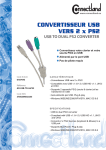
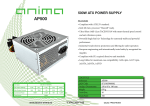
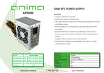
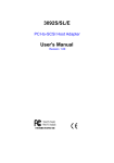
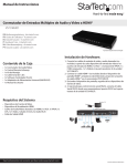
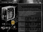
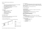
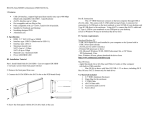
cPCI-SBC01 Board User manual cPCI-SBC01 (EMB-CPU01) User’s Manual Windows, Windows2000, Windows NT and Windows XP are trademarks of Microsoft. We acknowledge that the trademarks or service names of all other organizations mentioned in this document as their own property. Information furnished by DAQ system is believed to be accurate and reliable. However, no responsibility is assumed by DAQ system for its use, nor for any infringements of patents or other rights of third parties which may result from its use. No license is granted by implication or otherwise under any patent or copyrights of DAQ system. The information in this document is subject to change without notice and no part of this document may be copied or reproduced without the prior written consent. Copyrights 2007 DAQ system, All rights reserved. -1- http://www.daqsystem.com cPCI-SBC01 Board User manual Contents 1 . cPCI-SBC01 Introduction 2 . cPCI-SBC01 Appearance 3 . cPCI-SBC01 Assembly (Memory, Hard Disk) 4 . Peripheral Device Control through Compact PCI Interface(Back-Plane Connection) 5 . Expansion Port through Transition Board 6 . WINDOWS & Driver Installation -2- http://www.daqsystem.com cPCI-SBC01 Board User manual 1 . cPCI-SBC01 Introduction Introduction It is the low cost Single Board Computer(SBC) which equipped a low power and low heat processor. It provides solution to be suitable for Embedded market wanting low power and small size. Features Low cost, Low power and fan-less Single Board Computer AMD Geode LX800 500MHz processor 256Mb ~ 1Gb memory IDE Hard disk interface, (option)CF card VGA, (option) TFT LCD video output 2xUSB, 1xAudio (Transition board – 2xUSB, 2xPS2, RS232, 1xFDD, 1xLPT) Ethernet 10/100/1000M Embedded model available Operating Systems - Windows 2000/XP Specifications H/W • AMD Geode LX800 500MHz processor • 256MB, up to 1GB DDR SODIMM SDRAM • Compact Flash card (2G/4G/8G) (option) 1.8inch IDE HDD • 1920*1440 VGA output, (option) TFT LCD video output • AC’97 codec sound Physical Dimension • • 160 x 100 x 30 mm Front I/O : Power switch, D-sub video connector, 2xUSB, Ethernet, 2xStatus LED, Audio • Rear (transition) board : 2xUSB, 2xPS2, RS232, 1xFDD, 1xLPT • On-Board : LCD output, IDE Application Factory Automation Data acquisition Medical and Robotics Auto PC UMPC(Ultra Mobile PC) Instrument control PC -3- http://www.daqsystem.com cPCI-SBC01 Board User manual 2 . cPCI-SBC01 Appearance +5V External Power Front side SW,VGA,Network,USB Rear side Compact PCI interface - The cPCI-SBC01 board can use to personal PC with the external Power +5V. In front side of the cPCI-SBC01 have the Connector Out (VGA, Power S/W, Ethernet, 2xUSB, Power LED, Audio-Jack). - The cPCI-SBC01 board connects the Back-Plane at rear side. It can control the other devices through compact PCI interface. -4- http://www.daqsystem.com cPCI-SBC01 Board User manual 3 . cPCI-SBC01 Assembly(Memory, Hard Disk) 1. Memory(SODIMM – SDRAM) Connection - Memory Connection with J4 connector(256M ~ 1G) - CF card connector board (It is necessary to change the board if it connects 1.8” hard.) -5- http://www.daqsystem.com cPCI-SBC01 Board User manual - Hard Disk Connection (This picture is CF card connection.) Notice) It is necessary to change the board if it connects 1.8” hard. The picture shows differently above picture -6- http://www.daqsystem.com cPCI-SBC01 Board User manual 4 .Peripheral Device Control through Compact PCI Interface(Back-Plane) cPCI-SBC01 Switch Audio Usage – Our Product cPCI-EK01 VGA Ethernet 2xUSB The cPCI-SBC01 can control the other Compact PCI products as to connect BackPlane like above picture. -7- http://www.daqsystem.com cPCI-SBC01 Board User manual 5 . Expansion Port through Transition Board 2xUSB LPT FDD RS232 serial 2xPS2 Expansion rear interface IR The transition board can use through the Back-Plane. And It is possible to use the expansion ports with connect the cPCI-SBC01. (Special Purchase) -8- http://www.daqsystem.com cPCI-SBC01 Board User manual 6 . WINDOWS & Driver Installation 1. To connect a USB KEYBOARD and USB MOUSE and USB CD-ROM(WINDOWs CD) at Board. And, connect the power(5V, 3A) after connection to a DSUB 15 PIN VGA PORT and light up the switch. Notice) There isn’t an external power supply need in case of Back-Plane use. 2. When the computer boots, press the “F1” at the keyboard. And display the BIAS SET_UP. 3. After choose the “Boot Order”, Press “Enter”. 4. After choose the “USB CD-ROM Drive <- Conflict 4” at 1 line, and press down the “Esc”. -9- http://www.daqsystem.com cPCI-SBC01 Board User manual 5. After choose the “Save values and Exit”, and escape the display. 6. Booting is performed with a USB CD-ROM, you are able to progress a windows install guide. 7. After finished the Windows installation, you have to install the last Board driver. - There is Driver to CD-ROM enclosed like product. 7.1 AUDIO Driver Installation - MyComputer => Property => Hardware => Device Manager - Choose “Audio device”. - Click the right mouse, select the “driver update”. - Starting Hardware Update Wizard - Choose the Driver in AUDIO folder in CD ROM. 7.2 LAN Driver Installation - Execute SET-UP file in LAN folder in CD-ROM. 7.3 LCD Driver Installation(DISPLAY) - Choose the DRIVER in LCD folder in CD ROM. 7.4 VGA Driver Installation - Choose the DRIVER in VGA folder only used VGA. 7.5 Touch Installation(When 7” LCD want to use.) - After execute the Setup file in Touch folder in CD-ROM, display the icon of -10- http://www.daqsystem.com cPCI-SBC01 Board User manual TouchWare at the wallpaper. - Double click the TouchWare. - Click the “HW Info”. - Click the “Auto Search Touch” button, check the connection port. - After finding the port at Touch Controller, press “OK”. - Choose the “Calibrate” button. -11- http://www.daqsystem.com cPCI-SBC01 Board User manual - When show the below display, press the lighting point. (You should continuously press until completed progress bar.) - Press “Yes”, and then finished the install. 7.6 The optimum display set for the LCD. - Change the resolution 800x400 because LCD resolution is optimum 800x480. -12- http://www.daqsystem.com cPCI-SBC01 Board User manual - Choose the “Property” in wallpaper. - Click the “Advancd” in “Setting” in “Display Registration Information” display. - Click the “List All Modes” in “Adaptor” - Choose the “800 x 480 true color”. - Press “OK” and hit “Execute”. - If you see the red circle in the “Display Registration Information”. All progress succeed. -13- http://www.daqsystem.com