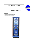
1
 User Manual
Vibration Analyser
Adash 4300 - VA3
FW 03.18
Ref: 20.04.2009 KM
Adash Ltd., Czech Republic, Tel.: +420 59 6232670, Fax: +420 59 6232671, e-mail: info@adash.cz
For further technical and contact information consult www.adash.net, www.adash.cz
Adash Ltd.
Adash 4300 - VA3
Contents
Before Switching On the Analyser ..................................................................................... 6
Indication of Weak Batteries (re-chargeables) .................................................................. 6
References........................................................................................................................... 7
Terminology......................................................................................................................... 8
The base scheme of A4300-VA3.................................................................................................. 8
List of Terms ................................................................................................................................. 8
Analyser Control, Important Keys.....................................................................................10
Selection of a Menu or Setting Screen Item and its Activation .........................................10
Return from the Menu................................................................................................................. 10
Return from the Setting Screen .................................................................................................. 10
Switching Between two Menus or Setting Screens .................................................................... 10
Deleting an Incorrectly Inserted Character or Figure ................................................................. 10
Switching of Capitals ON / OFF.................................................................................................. 11
Emergency Mode........................................................................................................................ 11
Instrument Keypad...........................................................................................................11
Interpretation of Basic Terms............................................................................................12
Static and Dynamic Data .................................................................................................12
Indication of Preparation and Course of Measurement ....................................................12
Types of Signal Processing..............................................................................................13
Measurement Averaging..................................................................................................13
Static Measurement Averaging .................................................................................................. 13
Dynamic Measurement Averaging ............................................................................................. 13
Description of the Basic Functions...................................................................................14
Analyser Power Supply....................................................................................................14
Procedure of Battery Exchange.................................................................................................. 14
Connecting Connectors ...................................................................................................14
Connection of a Vibration Sensor, ICP Supply .................................................................15
Switching on/off the Analyser...........................................................................................15
Analyser Main Menu...........................................................................................................16
Analyser Item...................................................................................................................16
Basic Measurements Item................................................................................................16
Speed Measurement .................................................................................................................. 16
Datacollector – Route Item...............................................................................................17
Memory Management Item ..............................................................................................17
Instrument Setup Item......................................................................................................17
Instrument Info Item .........................................................................................................17
Firmware Item..................................................................................................................18
Download from PC Item ............................................................................................................. 18
Delete form List Item................................................................................................................... 18
Use Item ..................................................................................................................................... 18
Analyser Menu....................................................................................................................20
Inputs and Sensors Item ..................................................................................................20
CHAN1 and CHAN2 Parameters................................................................................................ 20
ICP Parameter ............................................................................................................................ 20
SENSOR Parameter................................................................................................................... 21
UNIT Parameter.......................................................................................................................... 22
SENSIT Parameter ..................................................................................................................... 22
2
Adash Ltd., Czech Republic, Tel.: +420 59 6232670, Fax: +420 59 6232671, e-mail: info@adash.cz
For further technical and contact information consult www.adash.net, www.adash.cz
Adash Ltd.
Adash 4300 - VA3
RANGE Parameter ..................................................................................................................... 22
Trigger Inputs Item...........................................................................................................22
LEVEL Parameter....................................................................................................................... 23
DELAY Parameter ...................................................................................................................... 23
Wide-band Values Item....................................................................................................24
UPPER DISP and LOWER DISP Parameters ........................................................................... 25
DISP-UNIT Parameter ................................................................................................................ 25
MEAS-TIME Parameter .............................................................................................................. 25
EVALUATION Parameter ........................................................................................................... 26
BASE-BAND Parameter ............................................................................................................. 26
FREQ-BAND Parameter............................................................................................................. 26
Ampl. & phase measur. Item............................................................................................27
CHANNEL Parameter................................................................................................................. 27
AmEv format Parameter ............................................................................................................. 27
AMPL-UNIT, VIEW-UNIT, PHASE-UNIT and SPEED-UNIT Parameters.................................. 27
RESOL Parameter...................................................................................................................... 28
Dyn. Measur. - Setup Item ...............................................................................................28
Dynamic Measurements Item ..........................................................................................29
UPPER DISP and LOWER DISP Parameters ........................................................................... 29
DISP-UNIT Parameter ................................................................................................................ 29
EVALUATION Parameter ........................................................................................................... 29
Y-AXIS Parameter ...................................................................................................................... 30
Y-RANGE Parameter.................................................................................................................. 30
Measurements Memory Item ...........................................................................................30
Erasing Individual Items ............................................................................................................. 31
Dyn. Measur. - Setup Menu................................................................................................32
Time Signal Item..............................................................................................................32
BASE-BAND Parameter ............................................................................................................. 32
FREQ-BAND Parameter............................................................................................................. 33
Affect of a different bands on a measured signal ....................................................................... 34
Sampling frequency - fs .............................................................................................................. 35
SAMPLES Parameter ................................................................................................................. 35
TRIGGER Parameter.................................................................................................................. 35
TRIG-MODE Parameter ............................................................................................................. 36
AVERAGING Parameter ............................................................................................................ 36
AVER-NMB Parameter ............................................................................................................... 36
ENVELOPE Parameter............................................................................................................... 37
ACMT Item ......................................................................................................................37
The Compressed Time Signal Measurement............................................................................. 37
Spectrum Item .................................................................................................................38
LINES Parameter........................................................................................................................ 38
Other Parameters ....................................................................................................................... 38
ENV-Spectrum Item .........................................................................................................38
Order Analysis Item .........................................................................................................38
HARM-NMB Parameter .............................................................................................................. 39
RESOL Parameter...................................................................................................................... 39
List of Routes .....................................................................................................................40
Measurement of the Whole Measurement Point ..............................................................40
Dynamic Measurement with Machine Speed ...................................................................41
Creation of a Route Copy ................................................................................................41
Creation of a Machine Copy.............................................................................................41
Input and Display of a Note..............................................................................................41
Input of a Note ............................................................................................................................ 42
Display of the Note ..................................................................................................................... 42
Erasing of the Note ..................................................................................................................... 42
Creation of a Route..........................................................................................................42
3
Adash Ltd., Czech Republic, Tel.: +420 59 6232670, Fax: +420 59 6232671, e-mail: info@adash.cz
For further technical and contact information consult www.adash.net, www.adash.cz
Adash Ltd.
Adash 4300 - VA3
Route Sensor.............................................................................................................................. 42
Transmission of a Route to the Analyser or Data from the Analyser ......................................... 43
Instrument Setup Menu......................................................................................................44
Meas. Parameters Item....................................................................................................44
Impl. Input Parameter ................................................................................................................. 44
HP Integ. Parameter ................................................................................................................... 44
Unit Set Parameter ..................................................................................................................... 44
Frequency Parameter ................................................................................................................. 45
FFT-MODE Parameter ............................................................................................................... 45
SPEC Format and AmEv Format Parameters............................................................................ 45
SW Offset Parameter.................................................................................................................. 45
Route Parameters Item....................................................................................................46
Route Sensor Parameter ............................................................................................................ 46
Data Scanning Parameter .......................................................................................................... 46
Supply Cells Item.............................................................................................................46
Display.............................................................................................................................46
Control Keys of the Display Parameters Setting ........................................................................ 47
Date & Time Item.............................................................................................................47
Date Format Item........................................................................................................................ 47
Actual Date and Actual Time Items ............................................................................................ 47
Power Saving Item...........................................................................................................47
Control Keys of the Times Setting .............................................................................................. 48
Language Version Item....................................................................................................48
Instrument Info Menu .........................................................................................................49
Instrument Item................................................................................................................49
FW Versions Item ............................................................................................................49
Connectors Item ..............................................................................................................49
Batteries Item ..................................................................................................................49
Route Parameters Menu ....................................................................................................50
Route Sensor Item...........................................................................................................50
CHANNEL Parameter................................................................................................................. 50
Sensor Parameters..................................................................................................................... 50
Data Scanning Item .........................................................................................................51
Parameter Manual ...................................................................................................................... 51
Parameter Auto........................................................................................................................... 51
Alert level, Danger level and Preview time Items .............................................................51
Alert level and Danger level Parameters .................................................................................... 51
Preview time Parameter ............................................................................................................. 51
Memory Management Menu...............................................................................................53
Erase Measurements Memory .........................................................................................53
Displaying On-line Measurement Results ........................................................................54
Displaying Static Measurements Results .........................................................................54
Displaying Dynamic Measurement Results ......................................................................54
Arrow Keys Mode ....................................................................................................................... 55
Measurement Restart ................................................................................................................. 55
Measured Data Storage......................................................................................................56
Instrument Firmware Update .............................................................................................57
Necessary Equipment......................................................................................................57
File Installation............................................................................................................................ 57
Firmware New Version Files ............................................................................................58
Firmware Upload Procedure ............................................................................................58
Searching of the COM port number............................................................................................ 63
4
Adash Ltd., Czech Republic, Tel.: +420 59 6232670, Fax: +420 59 6232671, e-mail: info@adash.cz
For further technical and contact information consult www.adash.net, www.adash.cz
Adash Ltd.
Adash 4300 - VA3
Appendix A: Conflict of Setup versions, when you download FW to Software memory
.............................................................................................................................................64
Download of the FW with the same version number ........................................................64
Download of the FW with a later version number (newer FW)..........................................65
Download of the FW with earlier version number (older FW) ...........................................65
Appendix B: Keys You Use for a Number or Text Input ..................................................66
User Notes ..........................................................................................................................68
5
Adash Ltd., Czech Republic, Tel.: +420 59 6232670, Fax: +420 59 6232671, e-mail: info@adash.cz
For further technical and contact information consult www.adash.net, www.adash.cz
Adash Ltd.
Adash 4300 - VA3
Before Switching On the Analyser
Ignoring any recommendations mentioned below may cause failure of the instrument.
Operating with a power higher then 24 V can cause an accident.
1. Connect into the ICP input only:
- ICP powered sensor
- AC voltage max. 12 V peak-peak
- DC voltage max. +/- 24 V.
If you are not sure, contact your dealer or directly our website.
2. Never connect the analyser to a line voltage 230 V (110 V).
3. Only use batteries with a nominal voltage of max. 1.5 V.
Warning!
Be careful of battery orientation!
Indication of Weak Batteries (re-chargeables)
When you select the Instrument info from main menu, then information on the current condition of
the batteries appears.
While the instrument is switched on, the battery condition is checked every 30 sec.
1. When a warning low battery level is detected (insufficient to enable correct and safe work with
instrument), the yellow ERR light is on (on the top of keyboard). Finish your current
measurement and then change the batteries.
2. When the alert low battery level is detected, all three lights on the top of the keyboard blink
three times and instrument switches itself off. You have to change the batteries immediately. If
the instrument switches itself off after switch-on, then you also have to change the batteries
immediately.
Attention!
When the instrument is switched off for several
minutes, weak batteries can be regenerated and for
a limited time can seem to be in good condition.
Do not try repeatedly switching on, when the
instrument itself switches off immediately! You may
cause instrument failure and data in memory can be
corrupted.
6
Adash Ltd., Czech Republic, Tel.: +420 59 6232670, Fax: +420 59 6232671, e-mail: info@adash.cz
For further technical and contact information consult www.adash.net, www.adash.cz
Adash Ltd.
Adash 4300 - VA3
References
There is the vibration analyser and datacollector Adash 4300 – VA3 described in this manual.
This is the basic user manual of all the instruments of the Adash 4300 series, which contains the
important information on the correct use of the instrument.
Certain special features of the instruments of the Adash 4300 series are described in the special
manuals - see list below.
This manual is registered in the list of references as the [1] item.
This list of references is established for documentation set of Adash A4300-VA3 instruments:
[1]
[2]
[3]
[4]
[5]
[6]
Vibration Analyser Adash 4300-VA3; User manual
Vibration Analyser Adash 4300-VA3; Quick Start, User manual
Vibration Analyser Adash 4300-VA3; Multi FW upload, User manual
Vibration Analyser Adash 4300-Ex; User manual
Vibration Analyser Adash 4300-VA3; Balancing, User manual
Vibration Analyser Adash 4300-VA3; Cross Channel, User manual
7
Adash Ltd., Czech Republic, Tel.: +420 59 6232670, Fax: +420 59 6232671, e-mail: info@adash.cz
For further technical and contact information consult www.adash.net, www.adash.cz
Adash Ltd.
Adash 4300 - VA3
Terminology
The base scheme of A4300-VA3
A4300 - VA3 Instrument
VA3 Loader
memory
System data
Data memory
Software
(operational)
memory
PC
PC-Loader
DDS2000
…
RS232
List of Terms
FW - instrument firmware, it is internal software, which runs in the instrument processor.
FW module - individual FW for the instrument, it is software, which is able to run in the instrument. FW
modules are files, which you can download from Internet. Into the instrument is each FW module
transferred from PC disk by PC Loader software (A4300Loader1-1-13_en.exe, version nr. increases)
and by VA3 loader software (A4300_InitLoader_v137.b4f, version nr. increases).
License of FW module - the list of all licenses is saved in your instrument. When you have bought
the license for certain FW module, then you can download this module to the instrument memory.
Each user can buy all FW modules, which are offered. User receives every FW module through e-mail
and together with it also the init software, which rewrites the record with licenses in his instrument.
When you try download the firmware for which you have not the license, then the PC loader doesn’t
allowed it.
PC Loader – software in your PC (A4300Loader1-1-13_en.exe, version nr. increases), which provides
transfer of FW modules from PC disk to the instrument memory. The newest version is released on
Adash web site.
VA3 Loader - software in the instrument (A4300_InitLoader_v137.b4f, version nr. increases), which
provides saving and running of FW modules in the instrument. The newest version is released on
Adash web site.
8
Adash Ltd., Czech Republic, Tel.: +420 59 6232670, Fax: +420 59 6232671, e-mail: info@adash.cz
For further technical and contact information consult www.adash.net, www.adash.cz
Adash Ltd.
Adash 4300 - VA3
HW – hardware, obviously this word is used as general name for everything, what instrument contains
(boards, electronics components, display, connectors, keypad, …).
VA3 Loader Memory – memory in the instrument to which the VA3 Loader is saved.
Software (operational) memory – in this memory of the instrument is the actual FW module saved
and ran.
Data memory - memory in the instrument, in which all data (routes, FW modules, …) are saved.
Usual size is 12 MB. When you can compare it with PC, it is similar to PC hard disk.
System data - this part of the instrument memory contains various system blocks. For instance Setup
block contains all setups from instruments menus (by pushing Save button). FATsys block organizes saving of measurement data (similar to the FAT table in your PC).
Setup of FW module – the setup block contains all instrument settings. It is the part of system data
(see the diagram).
b4f - extension of file, which contains VA3 Loader or new licenses to write them into the instrument.
b4z - extension of file, which contains a FW module.
FW upload – general term for transfer of a FW module to the instrument memory. It is important to
assign to which instrument memory the transfer is made. It is the VA3 Loader memory for the VA3
Loader transfer. Individual FW modules can be saved either to the Software instrument memory or to
the Data instrument memory. Only the transfer to the software instrument memory was possible in the
past. That is why in older manuals the Data instrument memory is not mentioned, because transfer to
different place was not possible.
9
Adash Ltd., Czech Republic, Tel.: +420 59 6232670, Fax: +420 59 6232671, e-mail: info@adash.cz
For further technical and contact information consult www.adash.net, www.adash.cz
Adash Ltd.
Adash 4300 - VA3
Analyser Control, Important Keys
All the analyser functions are selected from menus.
Selection of a Menu or Setting Screen Item and its Activation
Select a menu or setting screen item by means of up/down arrows and by pressing right arrow,
ENTER or START, activate the selected function. An exception is, for example, settings screens from
which measurement can be launched. In such a case, start measurement by pressing START on any
menu item.
Return from the Menu
By pressing left arrow or START, close the selection in the current menu and return to the previous
menu. By pressing ESC, the last selection is cancelled.
Return from the Setting Screen
By pressing left arrow or ESC, close the selection in the current setting screen and return to the
previous menu. The performed selections are respected until the instrument is switched off. By
pressing Save the modified parameters are saved in the instrument permanent memory and further
respected.
Switching Between two Menus or Setting Screens
If two menus are displayed at the same time (this usually concerns the setup screens), they are
arranged horizontally or vertically. In both the cases, switch from one menu to another by pressing
PgUp or PgDn. The cursor is in the active menu. After switching to the other menu, the cursor will
appear at its original position before switching.
Deleting an Incorrectly Inserted Character or Figure
The last inserted character (e.g. name of measurement saved in the instrument memory or USERdefined numerical parameter) can be deleted by pressing
- up arrow for the A keypad design
- Shift left arrow for the B keypad design.
10
Adash Ltd., Czech Republic, Tel.: +420 59 6232670, Fax: +420 59 6232671, e-mail: info@adash.cz
For further technical and contact information consult www.adash.net, www.adash.cz
Adash Ltd.
Adash 4300 - VA3
Switching of Capitals ON / OFF
Capitals can be switched ON or OFF inside inserting of any text by pressing right arrow.
Emergency Mode
Press Setup key inside instrument switching ON to demand emergency mode. The brightness (of
50%) and contrast (of 63%) of display are set up at default values. Use the mode when the display
becomes illegible.
Instrument Keypad
ERR
ERR
STAT
M EAS
Sh ift
START
STAT
M EAS
ESC
START
+
+
ENTER
ESC
0
SPACE
0
ABC
DEF
SPACE
ABC
DEF
C o py
Cursor
P gU p
Co py
Cursor
PgU p
1
2
3
1
2
3
GHI
JKL
MNO
GHI
JKL
MNO
Sa ve
Mode
P gD n
Sa ve
Zo o m
PgD n
4
5
6
4
5
6
PQRS
TUV
WXYZ
PQRS
TUV
WXYZ
Delete
Se t up
Menu
Delete
Se t up
Me n u
7
8
9
7
8
9
A keypad design (version 1)
B keypad design (version 2)
11
Adash Ltd., Czech Republic, Tel.: +420 59 6232670, Fax: +420 59 6232671, e-mail: info@adash.cz
For further technical and contact information consult www.adash.net, www.adash.cz
Adash Ltd.
Adash 4300 - VA3
Interpretation of Basic Terms
Static and Dynamic Data
There are two main types of measured data in the 4300 instruments: static and dynamic.
Static data are represented by a single value (real or complex). An example is the result of
measurements of machine speed or vibration wide-band values.
Dynamic data are represented by an array of measured values. An example is the result of spectrum
or time signal measurement.
Static data parameters are set up and measured from a single setup screen to be activated from the
main menu by selecting
Analyser -> Wide-band values.
The measurement of dynamic data is launched from the setup screen to be activated from the main
menu by selecting
Analyser -> Dynamic measurements.
By pressing Setup in the Dynamic measurements screen, the setting screen of the corresponding
dynamic measurement appears.
Indication of Preparation and Course of Measurement
After pressing START from the measurement setup screen, the following steps are performed prior to
launching vibration measurements:
- Switching on ICP vibration sensor supply if it was off.
- Checking vibration sensor connection to the measurement input; an unconnected or defective
sensor will be indicated as an error.
- Auto-calibration of measurement range, if requested.
- Pause for transient performance on the signal path due to its re-setup.
The course of these preparations prior to measurement is indicated by a running graphic bar on the
bottom line of the display and by the MEAS signal light on the instrument panel:
Meas
Indicates
-----------------------------------------------------------------------------------------------------------------------------------Off
Measurement is not in progress or has been completed.
Red
Path auto-calibration or stabilisation, trigger sign occurrence etc. are expected.
Orange
The result of measurement is being calculated and prepared for display.
Green
Time signal is collected – measurement is in progress.
12
Adash Ltd., Czech Republic, Tel.: +420 59 6232670, Fax: +420 59 6232671, e-mail: info@adash.cz
For further technical and contact information consult www.adash.net, www.adash.cz
Adash Ltd.
Adash 4300 - VA3
Types of Signal Processing
Input signal can be processed and modified in case of alternate measurements in various ways; with
respect to measurement, we always speak about the selection of a signal path. The following table
describes the features of four signal paths used in the Adash 4300 instruments.
Path
Sensor Unit Unit of Meas.
Description
=============================================================================
2
2
No modifications
m/s , g
m/s , g
Acceleration meas. by an accel. sensor
mm/s, in/s
mm/s, in/s
Velocity measurement by a velocity sensor
um, mil
um, mil
Displacement meas. by a displ. sensor
2
Integration
m/s , g
mm/s, in/s
Velocity meas. by an acceleration sensor
mm/s, in/s
um, mil
Displacement meas. by a velocity sensor
2
Double integration
m/s , g
um, mil
Displacement meas. by an accel. sensor
2
2
ENV modulator
m/s , g
m/s , g
Measurement of envelope modulated
mm/s, in/s
mm/s, in/s
signal. The unit of measurement is identical
um, mil
um, mil
to the sensor unit.
CAUTION.
- The analyser will automatically set the correct measurement path according to the currently
set sensor unit (see Chapter Analyser Menu/Inputs and Sensors Item/Unit Parameter) and
according to the requested unit of measurement (see Chapter Analyser Menu/Wide-band
Values Item or Dynamic Measurements/Unit Parameter).
- Double integration instruments are supplied upon special request.
- The ENV measurement path is not implemented in the firmware 1.0 and 1.1 versions.
Measurement Averaging
Static Measurement Averaging
For static measurements, the number of measurements based on which the final averaged static
value is to be calculated is not entered. Measurement averaging is carried out by setting a suitable
measurement time parameter MEAS-TIME by selecting Analyser->Wide-band Values from the main
menu.
The entered measurement time value determines the length of time signal in seconds based on which
the static value is then calculated. A longer time of measurement thus corresponds to a higher
measurement result averaging.
Dynamic Measurement Averaging
The request for dynamic measurement averaging is fulfilled by setting the AVERAGING parameter to
TIME or LIN. Call the appropriate setting screen by selecting Analyser->Dynnamic measurements
from the main menu and pressing Setup key.
In the next AVG-NMB parameter, the requested number of measurement averages can be set.
CAUTION! If the AVERAGING parameter is set to OFF, then the number of averages set in the AVGNMB parameter is not respected and measurement is not averaged. If you need measurement
averaging, make sure you set the AVERAGING parameter to TIME or LIN.
13
Adash Ltd., Czech Republic, Tel.: +420 59 6232670, Fax: +420 59 6232671, e-mail: info@adash.cz
For further technical and contact information consult www.adash.net, www.adash.cz
Adash Ltd.
Adash 4300 - VA3
Description of the Basic Functions
Analyser Power Supply
The analyser is supplied by 4 batteries of AA size with a nominal voltage of max. 1.5 V.
1. To supply the analyser, the following can be used:
- batteries with a nominal voltage of 1.2 V
- alkaline cells (not another type) with a nominal voltage of 1.5 V.
2. Do not combine various types of supply cells, always mount 4 identical pieces.
3. Carefully check polarity of the inserted cells - by reversing polarity of any of the cells,
supply cells get damaged.
4. Select the right cells type via the item Main menu->Instrument setup->Supply cells.
Information on the condition of batteries is available by selecting Instrument Info from the main menu.
Procedure of Battery Exchange
-
Switch off the analyser by pressing ESC+START.
Release the screw of the battery area cover.
Exchange the discharged batteries with charged ones, pay attention to the correct polarity
of each battery.
Install the cover and tighten the screw.
Switch on the analyser by pressing START.
Activate the Instrument Info -> Batteries screen from the Main Menu and check the
condition of the installed batteries.
Connecting Connectors
-
-
-
-
On its upper side, the analyser is equipped with a seven-pin connector to connect a vibration
sensor. The sensor connected to this input is further indicated CHAN1. ICP supply of the
connected vibration sensor is conducted to the connector.
On its left side, the analyser is equipped with a seven-pin connector to connect a second
vibration sensor. The sensor connected to this input is further indicated CHAN2. ICP supply
of the connected vibration sensor is conducted to the connector.
On its right side, the analyser is equipped with a five-pin connector to connect a trigger pulse
source, usually a tachoprobe. The sensor connected to this input is further indicated TRG.
The connected tachoprobe supply is conducted to the connector.
On its lower side, the analyser is equipped with a nine-pin connector Canon to connect the
serial communication RS232 (usually for the transmission of measured data from the
analyser to the user PC or for route recording from the user PC to the analyser). A
tachoprobe can also be connected to this connector to ensure compatibility with probes of the
Adash 4100 and Adash 4200 analysers.
14
Adash Ltd., Czech Republic, Tel.: +420 59 6232670, Fax: +420 59 6232671, e-mail: info@adash.cz
For further technical and contact information consult www.adash.net, www.adash.cz
Adash Ltd.
Adash 4300 - VA3
Connection of a Vibration Sensor, ICP Supply
On its upper side, the analyser is equipped with a seven-pin connector to connect a vibration sensor
with ICP supply. The analyser has its own sensor ICP supply. Set the type and parameters of the
used sensor and the sensor ICP supply switching on/off by selecting Analyser->Inputs and Sensors
from the main menu.
-
The left screen (CHAN1) defines the parameters of a sensor connected to the connector on
the upper side of the instrument.
The right screen (CHAN2) defines the parameters of a second sensor connected to the
connector on the left side of the instrument.
To switch from the one side of the display to the other, press PgUp or PgDn.
Once the parameters are set, leave the screen by pressing left arrow or ESC. By pressing
Save, store the current setting of the instrument to its permanent memory.
CAUTION! The currently used setting of the instrument, including new modifications, is valid only
until the instrument is switched off. Once it is switched on, the original setting is downloaded from
its permanent memory. If you wish to save the current setting of the instrument to the permanent
memory, press Save.
Sensor parameter setting – see Chapter Analyser Menu/Inputs and Sensors Item.
Switching on/off the Analyser
By pressing START, switch on the analyser and the introductory logo appears on the display. After
several seconds, the main menu appears on the display to select further steps of the analyser.
By pressing ESC+START, switch off the analyser.
If, after switching on the instrument, a floppy disk logo (before 1.37 Loader version) or A4300
Loader title (form 1.37 Loader version) is shown instead of the main menu, it means that the analyser
firmware has been damaged and the instrument expects the firmware to be uploaded to the memory.
The procedure is described in the chapter Instrument Firmware Update.
In this mode the analyser does not respond to any keystroke; can be switched off only. If firmware is
not uploaded, then the instrument automatically switches off after approx. 2 minutes.
The floppy disk logo
or A4300 Loader title
on the display means
a firmware failure.
15
Adash Ltd., Czech Republic, Tel.: +420 59 6232670, Fax: +420 59 6232671, e-mail: info@adash.cz
For further technical and contact information consult www.adash.net, www.adash.cz
Adash Ltd.
Adash 4300 - VA3
Analyser Main Menu
After switching on the analyser, the Main Menu is displayed.
By pressing up/down arrows, select the requested item and activate it by pressing right arrow,
ENTER or START.
Analyser Item
It enables the instrument to pass to the analyser mode, therefore to the on-line measurement mode.
After it is activated, the Analyser menu is displayed. A detailed description of its individual items is
indicated in the chapter Analyser Menu.
Basic Measurements Item
It offers a menu to perform 4 basic predefined types of measurement
ISO
velocity RMS and PEAK values measurement [mm/s] or [in/s] in band 10-1000 Hz
Bearing
acceleration RMS and PEAK values measurement [g] in band 5-16 kHz - common
bearing
L-Bearing
acceleration RMS and PEAK values measurement [g] in band 0.5-16 kHz - large
bearing
Machine speed machine speed value [CPS] and [RPM].
The measurement results can be stored in the analyser memory as if they were obtained in a
standard measurement in the Analyser mode - see chapter Measured Data Storage.
The Measurements Memory item enables to view measurement results saved in the analyser
memory – see chapter Analyser Menu/Measurements Memory Item.
CAUTION!
- The ISO, Bearing and L-Bearing items are only available if the ACC sensor type, i.e.
accelerometer, is set. Otherwise, the last two acceleration measurements [g] could not be
performed.
- Since they are predefined measurements, it is supposed that the sensor is connected to the
input set by the Impl. Input parameter – see chapter Instrument Setup/Meas. Param. The
sensor parameters (including the ACC type) are defined by the setting screen of the relative
CHAN1 or CHAN2 input – see chapter Analyser menu/Inputs and Sensors.
- Set the ISO measurement unit via Units parameter – see chapter Instrument Setup Menu Meas. Param. Item.
- By pressing Setup, invoke the Meas. Param. setting screen and switch the Impl. Input or the
Units parameters.
Speed Measurement
1. The simplest way to measure speed, is to use Main menu -> Basic measurements ->
Machine speed item.
16
Adash Ltd., Czech Republic, Tel.: +420 59 6232670, Fax: +420 59 6232671, e-mail: info@adash.cz
For further technical and contact information consult www.adash.net, www.adash.cz
Adash Ltd.
Adash 4300 - VA3
2. Open the Wide-band values screen (Main menu -> Analyser -> Wide-band values). The
UPPER DISP or LOWER DISP parameter set to TRG (trigger input). Then select
measurement unit (CPS, RPM). By pushing START take the speed measurement.
CAUTION!
An error appears if the instrument is connected to your PC via RS232 cable during machine
speed measurement.
Datacollector – Route Item
It enables the instrument to pass to the datacollector mode, i.e. to the viewing and/or route
measurement mode. After it is activated, the list of routes in the instrument memory is displayed,
indicated as Datacollector - Route.
This item is available only with instruments that are equipped with a program module for route
measurements.
A detailed description of how to work with the list of routes is included in chapter List of Routes.
Memory Management Item
It enables to erase all the files and measured static and dynamic data, saved in the instrument
memory. It is:
- The list of routes and measured data of individual routes.
- Data measured by the analyser and saved in the memory.
- Balancing projects and their measured data.
- FW modules.
The whole instrument memory that is reserved for data and files storage, is erased and initialised see also chapter Memory Management Menu.
Instrument Setup Item
It enables the instrument to pass to the parameter setup mode. After it is activated, the Instrument
Setup menu is displayed. For a detailed description of its individual items see chapter Instrument
Setup Menu.
Instrument Info Item
It enables the instrument to pass to the mode when information relative to the instrument setting and
to the version of the installed firmware is displayed. After it is activated, the Instrument Info menu is
displayed. For a detailed description of its individual items see chapter Instrument Info Menu.
17
Adash Ltd., Czech Republic, Tel.: +420 59 6232670, Fax: +420 59 6232671, e-mail: info@adash.cz
For further technical and contact information consult www.adash.net, www.adash.cz
Adash Ltd.
Adash 4300 - VA3
Firmware Item
It enables to simplify the switching over FW modules. Any new FW module has to be stored into the
program instrument memory from a PC via the RS232 interface – see Instrument Firmware Update
chapter. Any new FW versions actualisation can be carried out via this way only.
To switch over FW modules there is useful if all the FW modules are stored in the instrument data
memory and ready to be loaded from here into the instrument program memory without connecting the
instrument to PC via RS232 interface.
CAUTION! If the Erase measurements memory command is executed all FW modules are removed
from the data instrument memory and they have to be stored from your PC via RS232 interface. This
command has no effect upon the current FW module in the instrument program memory.
Check whether the version of instrument loader is V1.37 or later. Previous
loader versions do not support the functions described below. Use the
standard update FW modules way via RS232 interface to update new loader
version in your instrument. The InitLoader_v137.b4f file is available on the
www.adash.cz.
In the documentation [3] you can find detail information on how to handle FW modules – see
chapter References.
Download from PC Item
It enables to store a FW module from PC to the instrument data memory. The instrument prompts you
to establish serial communication via RS232 interface: Use 4300Loader on PC please… The select
FW module will be stored into the instrument data memory. The operation has no effect upon the
current FW module in the instrument program memory.
See the Instrument Firmware Upload chapter how to establish serial communication via A4300Loader program and how to handle the program.
Select any FW module from the offered list and click the Wait for instrument button. If the
communication is established click the Upload button to store the select FW module into the
instrument data memory. Two steps of the loading are executed:
- The initializing FW part is stored.
- FW module is stored.
Delete form List Item
It enables to remove the select FW module from the instrument data memory. Use the item to remove
any FW module before replacing by its later version. The previous version is not necessary to archive.
Select any module from the offered list and press the START button. Select module will be removed.
Use Item
It enables to load the select FW module from the instrument data memory to the program memory.
The loaded module is run immediately.
18
Adash Ltd., Czech Republic, Tel.: +420 59 6232670, Fax: +420 59 6232671, e-mail: info@adash.cz
For further technical and contact information consult www.adash.net, www.adash.cz
Adash Ltd.
Adash 4300 - VA3
Select any module from the offered list and press the START button. Initialising part from the select
module will be loaded and run first and the select firmware will be loaded and run immediately.
For older FW modules then the 03.04.1 version only:
Do not use FW modules with different versions of setup – see chapter
Instrument Info Menu / FW Versions Item. If an older version is
downloaded into instrument the all data in setup block are set to default
values. Especially – sensors user sensitivities are overwritten.
19
Adash Ltd., Czech Republic, Tel.: +420 59 6232670, Fax: +420 59 6232671, e-mail: info@adash.cz
For further technical and contact information consult www.adash.net, www.adash.cz
Adash Ltd.
Adash 4300 - VA3
Analyser Menu
By activating the Analyser item in the instrument main menu, activate the Analyser menu. The
instrument passes to the analyser mode, i.e. on-line measurements.
-
By pressing up/down arrows, select the requested item and activate it by pressing right
arrow, ENTER or START.
By pressing left arrow or ESC, return to the analyser main menu.
By pressing Save, save the current analyser setting to the instrument permanent memory.
By pressing Setup, invoke the Meas. Param setting screen – see Chapter Instrument Setup
Menu/Meas. Param. Item.
Inputs and Sensors Item
It enables to pass to the setting screen of vibration or DC measurement sensors.
-
The left screen (CHAN1) defines the parameters of a sensor connected to the connector on
the upper side of the instrument.
The right screen (CHAN2) defines the parameters of a second sensor connected to the
connector on the left side of the instrument.
To switch from one side of the screen to the other, press PgUp or PgDn.
Select the item by means of up/down arrows and activate by pressing right arrow or
ENTER.
Once the parameters are set, leave the screen by pressing left arrow or ESC. By pressing
Save, store the current setting of the instrument to its permanent memory.
-
CHAN1 and CHAN2 Parameters
It defines the type of sensor. The firmware current version supports the following types:
OFF
AC
DC
The sensor is disconnected and it cannot be assigned to measurements on the setup
screens. If the second sensor, connected to the left connector, is not used, it is advisable to
set CHAN2 to OFF.
A sensor for alternate measurements is connected to the relative connector.
A sensor for direct-current measurements is connected to the relative connector.
ICP Parameter
It defines the request for the sensor ICP supply to be switched on.
ON
OFF
During measurement the sensor ICP supply is ON. This is a standard setting for the use of a
vibration sensor with ICP supply.
During measurement, the sensor is not connected to the ICP supply source. Use this setting if
you want to measure signal from the signal generator or vibration sensor that is already
supplied from another source (e.g. the analyser is connected parallelly with another measuring
instrument supplied by the sensor).
If the sensor is not connected to an external ICP supply source, the analyser internal supply
source must be ON. Otherwise, an error message is displayed after launching the measurement.
20
Adash Ltd., Czech Republic, Tel.: +420 59 6232670, Fax: +420 59 6232671, e-mail: info@adash.cz
For further technical and contact information consult www.adash.net, www.adash.cz
Adash Ltd.
Adash 4300 - VA3
In such a case, interrupt measurement and switch on the internal ICP supply.
SENSOR Parameter
It defines the subtype of the connected sensor.
The following subtypes can be selected for the alternate AC type of sensor:
VOLT Voltage sensor. Use this option for the measurement of voltage from the signal source. In this
case signal cannot be integrated.
ACC Acceleration sensor – accelerometer. The sensor enables to measure acceleration (directly),
velocity (via an integrator) and displacement (via a double integrator).
VEL
Velocity sensor. The sensor enables to measure velocity (directly) and displacement (via an
integrator).
DISP Displacement sensor. The sensor enables to measure displacement (directly).
Sensor
Sensor Unit
Measured Quantity
Unit of Meas.
Meas. Path
-------------------------------------------------------------------------------------------------------------------------------------VOLT
mV, V
voltage
mV, V
direct
2
ACC
m/s , g
voltage
mV, V
direct
2
acceleration
m/s , g
direct
velocity
mm/s, in/s
integrator
displacement
um, mil
2x integrator
VEL
mm/s, in/s
voltage
mV, V
direct
velocity
mm/s, in/s
direct
displacement
um, mil
integrator
DISP
um, mil
voltage
mV, V
direct
displacement
um, mil
direct
CAUTION. The measurement path double integrator is defaultly not enabled.
The instrument contains two measurement paths. Each measurement path contains one integrator
and one filter. If a double integration is required for measurement, then the integrator from the other
path is used. Double integration is possible only for a single channel measurement, so it is not
possible to use for the Cross Analyser firmware. Using of the two filters is similar to using of the two
integrators. If a band-pass filter is required for measurement, then a high-pass filter from the other
path is used. Dual channel measurements are possible only with a low-pass filter.
Recommendation:
For a measurement of Amplitude-phase-speed is recommended to set parameters as follows (see
chapter Analyser Menu – Ampl. & phase measur. Item):
2
- AMPL-UNIT parameter: set the unit of sensor (e.g. for an accelerometer: g, m/s )
- VIEW-UNIT parameter: set a desired unit for measurement (e.g. for measurement of displacement:
mil, µm).
The µm and mil units are always enabled in this case (µm and mil units correspond to double
integration of acceleration). The same settings are enabled for the balancing (see firmware Balancer)
and you can always use the displacement units for a balancing.
The following subtypes can be selected for the direct-current DC type of sensor:
VOLT Voltage sensor. Use this option for the measurement of voltage from the signal source.
USER User sensor.
21
Adash Ltd., Czech Republic, Tel.: +420 59 6232670, Fax: +420 59 6232671, e-mail: info@adash.cz
For further technical and contact information consult www.adash.net, www.adash.cz
Adash Ltd.
Adash 4300 - VA3
Sensor
Sensor Unit
Measured Quantity
Unit of Meas.
Meas. Path
-------------------------------------------------------------------------------------------------------------------------------------VOLT
mV, V
voltage
mV, V
direct
USER
USER
USER
USER
direct
UNIT Parameter
It defines the unit of the sensor in which its sensitivity will be indicated. Only such units are offered
that correspond to the selected sensor subtype - see the description of the SENSOR parameter
(Sensor Unit) above.
SENSIT Parameter
It defines the sensitivity of the sensor used in mV per sensor unit determined by the UNIT parameter.
The following nominal sensitivity of the sensor can be selected: 1, 5, 10, 50, 100, 500 and 1000
mV/UNIT. If you know the effective sensitivity of the sensor used, enter it via the user selection
USER.
RANGE Parameter
It defines the measurement range in the sensor unit defined in the UNIT parameter. According to the
selected fixed measurement range, the instrument input amplifiers are set. If you use the AUTO
option, the optimal measurement range will be set prior to launching the measurement.
CAUTION!
- The measurement range is defined in the sensor unit, not in the unit of measurement. If you
measure velocity, for instance via an integrator, in mm/s by means of an acceleration sensor
with the sensor unit g, select the range of the input signal also in the sensor unit g.
- For common measurements, it is advisable to select the AUTO range and to use the fixed
measurement range only for cases that necessarily require it.
- If you select the fixed measurement range, it is advisable to first test the measured signal, for
instance by measuring time signal for a gradually reducing measurement range, and thus to
determine the selected range with a sufficient reserve. If the selected range is restricted, the
instrument input part is overexcited during measurement and measurement is not be
performed. If, on the contrary, the selected range is excessive, measurement precision is lost
due to interference and noise of the measured signal.
Trigger Inputs Item
It enables to pass to the setup screen of trigger inputs.
-
The left screen (TRIGGER) defines the parameters of the trigger connected to the TRG
connector on the right side of the instrument.
The right screen (INPUT-SIGNAL) defines the parameters of the trigger represented by the
vibration sensor of the measured signal.
To switch from one side of the screen to the other, press PgUp or PgDn.
Select the item by means of up/down arrows and activate by pressing right arrow or
ENTER.
Once the parameters are set, leave the screen by pressing left arrow or ESC. By pressing
Save, store the current setting of the instrument to its permanent memory.
22
Adash Ltd., Czech Republic, Tel.: +420 59 6232670, Fax: +420 59 6232671, e-mail: info@adash.cz
For further technical and contact information consult www.adash.net, www.adash.cz
Adash Ltd.
Adash 4300 - VA3
It enables to set measurement synchronisation and precise start of a measurement. It can be set to
the four modes:
Free run: Trigger is not used. After pushing the START button is set the range and then immediately
the measurement starts. This mode is suitable for measuring of the standard machines, which process
is stable.
Manual: Trigger is initialized manually. After pushing the button START is instrument get to ready (set
range). The measuring is exactly started by re-pushing the button START. This mode is suitable for
measuring of machines, which operate in some modes.
E.g. the mechanical hand shifts boxes. It operates in the several modes. When I need to measure in
exact mode, e.g. when hand moves the box, then I use the manual trigger.
External: Trigger is initialized by an external DC voltage source (max. 24V) which is connected to the
TRIGGER input. A tachoprobe (photocell) is usually used as the DC voltage source.
Signal: In this mode the measurement is triggered by level of a signal. When the signal level is higher
then set trigger level, then measurement is run. This mode is suitable e.g. for bump test. For signal
trigger you have to use the FIX RANGE of input (Analyser - Inputs & sensors - RANGE) and set the
LEVEL of trigger. LEVEL of trigger is relative value in percents of the input range. The signal mode is
recommended to use with setting DELAY<0 (pre-trigger).
If the trigger is set and measurement is started (START button), then the instrument waits for the
trigger.
LEVEL Parameter
It corresponds to the level of vibration signal. If the level of vibration exceeds the LEVEL parameter,
then the measurement starts. The LEVEL parameter is used only for EXTERNAL and SIGNAL mode
of the trigger.
- EXTERNAL (e.g. optical probe): it is defined in the left-side of the display. Level value is DC voltage
in mV. If DC voltage from a source exceeds the level limit, then the measuring is started.
- SIGNAL (percent of a fix-range): it is defined in the right-side of the display. Level value is percent of
range. Range has not to be AUTO and must be set by user.
2
E.g. If the range is 10m/s and LEVEL is 10 percents, then measurement starts when the level of a
2
signal exceeds 1m/s .
DELAY Parameter
Delay parameter is defined in % of the actual record length. It is defined for all trigger modes:
DELAY = 0
The signal starts exactly at the trigger time.
DELAY < 0
The signal contains time before the trigger (pretrig).
DELAY > 0
The signal starts after the trigger (posttrig).
E.g. If record length is 500ms then:
DELAY = -20, the measurement starts 125ms before trigger
DELAY = +20, then the measurement starts 125ms after trigger
23
Adash Ltd., Czech Republic, Tel.: +420 59 6232670, Fax: +420 59 6232671, e-mail: info@adash.cz
For further technical and contact information consult www.adash.net, www.adash.cz
Adash Ltd.
Adash 4300 - VA3
Signal Trigger mode:
External Trigger mode:
Wide-band Values Item
It enables to pass to the setup and measurement screen of static values.
-
The upper display (UPPER DISP) defines measurement parameters shown in the upper part
of the display.
24
Adash Ltd., Czech Republic, Tel.: +420 59 6232670, Fax: +420 59 6232671, e-mail: info@adash.cz
For further technical and contact information consult www.adash.net, www.adash.cz
Adash Ltd.
-
Adash 4300 - VA3
The lower display (LOWER DISP) defines measurement parameters shown in the lower part
of the display.
To switch from one part of the display to the other, press PgUp or PgDn.
Select the item by means of up/down arrows and activate by pressing right arrow or
ENTER. By pressing START, launch measurement.
Once the parameters are set, leave the screen by pressing left arrow or ESC. By pressing
Save, store the current setting of the instrument to its permanent memory.
By pressing Setup, invoke the Inputs and Sensors setting screen – see Chapter Analyser
Menu/Inputs and Sensors Item.
By pressing START, launch measurement with the currently set parameters.
If you do not request to carry out two parallel measurements in the upper and lower display, set one
part of the display to OFF - see below. A single measurement is faster. When switching either part
of the display to/from OFF, the set measurement parameters of each part of the display remain.
CAUTION. Set UPPER/LOWER DISP and DISP-UNIT parameters for direct-current measurements
only.
UPPER DISP and LOWER DISP Parameters
They enable to assign the upper (UPPER) and lower (LOWER) part of the display to the
measurement input and to set measurement parameters. The following assignments to the
measurement input are possible:
OFF
CH1
CH2
TRG
The relative part of the display does not measure. A single measurement is performed,
defined by the parameters of the other part of the display.
Measurement will be performed from the sensor connected to the input on the upper side of
the instrument (CHAN1).
Measurement will be performed from the second sensor connected to the input on the left side
of the instrument (CHAN2).
Speed will be measured from a tachoprobe connected to the connector on the right side of
the instrument or to the Canon connector on the lower side of the instrument.
CAUTION! If the CH1 or CH2 item fails to appear in the menu and you require measurement at this
input, check whether the relative CHAN1 or CHAN2 is enabled – see chapter Analyser Menu/Inputs
and Sensors/CHAN1 and CHAN2 Parameters. By pressing Setup, invoke the appropriate setting
screen.
DISP-UNIT Parameter
It defines the unit of measurement. The menu offers only such units that can be used for the particular
measurement – see chapter Analyser Menu/Inputs and Sensors/SENSOR Parameter – Unit of
Measurement. To measure speed, the following units are available CPS (revolutions per second) and
RPM (revolutions per minute).
MEAS-TIME Parameter
It defines measurement time in seconds. Set 0.25 sec for fast measurements, 1 sec for common
measurements and a longer time for special measurements. The selection of a longer time of
measurement means that measurement averaging is requested from a longer time signal. The
USER option of measurement time is possible the value is entered as an integer.
CAUTION! If you request parallel measurements on both parts of the display, it is advisable to select
the same measurement time for both measurements.
25
Adash Ltd., Czech Republic, Tel.: +420 59 6232670, Fax: +420 59 6232671, e-mail: info@adash.cz
For further technical and contact information consult www.adash.net, www.adash.cz
Adash Ltd.
Adash 4300 - VA3
EVALUATION Parameter
It defines the type of the final statistic value. The following options are available:
RMS
0-P
P-P
ENV-RMS
ENV-0-P
CREST
KURTOSIS
true RMS value measurement
true PEAK value measurement
true PEAK-PEAK value measurement
true RMS value measurement via an envelope modulator
true PEAK value measurement via an envelope modulator
CREST factor measurement
KURTOSIS factor measurement
This is an ideal case for parallel measurements on two screens. All parameters, with the
exception of EVALUATION, are set to the same values and two static parameters of the
input signal are measured simultaneously (with the exception of ENV-RMS).
BASE-BAND Parameter
It defines the basic frequency measurement range in Hz or CPM from which sampling frequency for
dynamic measurements is derived based on the following relation: fs = 2.56 x BASE-BAND. To
measure static values, the sampling frequency is fixed (approx. 50 kHz). The Hz or CPM unit is set
via the Frequency parameter – see chapter Instrument Setup Menu / Meas. Param. Item /
Frequency Parameter. If the BASE-BAND frequency is set in the FREQ-BAND parameter, static
values are measured in band 0.8 Hz (48 CPM) to BASE-BAND. The USER option of the basic range
is possible if menu options are not suitable.
For more information see chapter Dyn. Measur. - Setup menu - Time Signal Item.
CAUTION. This parameter is identical to the like parameter of the dynamic measurements setting
screens. A setting from any screen is reflected in the setting of another screen.
FREQ-BAND Parameter
It defines the frequency band of measurement in Hz or CPM. The Hz or CPM unit is set via the
Frequency parameter – see chapter Instrument Setup Menu / Meas. Param. Item / Frequency
Parameter. The following options are available:
BASE-BAND
FL-FH
USER
It is measured in band 0.8 Hz (48 CPM) to BASE-BAND.
It is measured in the band defined by a selected menu item.
The user setting of the frequency band of measurement is performed by selecting the
appropriate lower (Freq-low >= 20 Hz, 1,200 CPM) and upper (Freq-high <= 19,200
Hz, 1,152,000 CPM) frequency.
For more information see chapter Dyn. Measur. - Setup menu - Time Signal Item.
26
Adash Ltd., Czech Republic, Tel.: +420 59 6232670, Fax: +420 59 6232671, e-mail: info@adash.cz
For further technical and contact information consult www.adash.net, www.adash.cz
Adash Ltd.
Adash 4300 - VA3
Ampl. & phase measur. Item
It enables to pass to the setting and measurement screen of amplitude and phase of the input
signal at the machine speed frequency.
-
Select the item by means of up/down arrows and activate by pressing right arrow or
ENTER. By pressing START, launch measurement.
Once the parameters are set, leave the screen by pressing left arrow or ESC. By pressing
Save, store the current setting of the instrument to its permanent memory.
By pressing Setup, invoke the Inputs and Sensors setting screen – see Chapter Analyser
Menu/Inputs and Sensors Item.
By pressing START, launch measurement with the currently set parameters.
The measurement proceeds from the order analysis measurement - see chapter Dyn. Measur. –
Setup menu / Order analysis Item.
This measurement has to be externally synchronized and the machine speed measurement is
executed within its framework.
The tachoprobe is need for this measurement.
CHANNEL Parameter
It enables to assign the measurement to a measurement input. The following assignments to the
measurement input are possible:
OFF
CH1
CH2
No measurement is performed.
Measurement will be performed from the sensor connected to the input on the upper side of
the instrument (CHAN1).
Measurement will be performed from the second sensor connected to the input on the left side
of the instrument (CHAN2).
CAUTION! If the CH1 or CH2 item fails to appear in the menu and you require measurement at this
input, check whether the relative CHAN1 or CHAN2 is enabled – see chapter Analyser Menu/Inputs
and Sensors/CHAN1 and CHAN2 Parameters. By pressing Setup, invoke the appropriate setting
screen.
AmEv format Parameter
It enables to select Amplitude Evaluation format - see chapter Instrument Setup Menu / Meas.
Param. Item / SPEC format and AmEv format Parameters.
AMPL-UNIT, VIEW-UNIT, PHASE-UNIT and SPEED-UNIT Parameters
They enable to select desired measurement and display units.
Amplitude measurement unit - AMPL-UNIT
It depends on the sensor type and on the instrument FW, then there need not all units of the following
list to be reached in any time.
2
- Acceleration measurement units:
m/s , g.
- Velocity measurement units:
mm/s, in/s.
- Displacement measurement units:
µm, mil.
Recommendation.
27
Adash Ltd., Czech Republic, Tel.: +420 59 6232670, Fax: +420 59 6232671, e-mail: info@adash.cz
For further technical and contact information consult www.adash.net, www.adash.cz
Adash Ltd.
-
Adash 4300 - VA3
Set the measurement unit like the sensor unit - see chapter Analyser Menu / Inputs and
Sensors Item / UNIT Parameter.
Sensor
Sensitivity
Machine speed
acceleration
100 mV/g
over 10 CPS (600 RPM)
acceleration
500 mV/g
over 5 CPS (300 RPM)
velocity
--under 5 CPS (300 RPM)
Amplitude display unit – VIEW-UNIT
It enables to select an amplitude display unit – see units list as follows:
2
- Acceleration display units:
m/s , g.
- Velocity display units:
mm/s, in/s.
- Displacement display units:
µm, mil.
Phase measurement unit – PHASE-UNIT
There is possible to select either the rad (radian) unit or the deg (degree of angle) unit. The phase is
measured in ±π or ±180º ranges.
Machine speed unit – SPEED-UNIT
There is possible to select either the CPS (cycles per second or Hz) unit or the RPM (revolutions per
minute) unit.
RESOL Parameter
Defines the frequency resolution in Hz of each order (from ±0.5 to ±10) or in CPM (from ±30 to ±600).
The Hz or CPM unit is set via the Frequency parameter – see chapter Instrument Setup Menu /
Meas. Param. Item / Frequency Parameter.
For instance, if two frequencies are mixed in signal, then you need for correct stable phase and
amplitude to set smaller resolution the difference between them.
See Note and Example in chapter Dyn. Measur. – Setup Menu / Order Analysis Item / RESOL
Parameter.
Dyn. Measur. - Setup Item
This item is not offered in menu from FW version 03.05. Call the appropriate setting screen from
dynamic measurement screen by Setup key – see chapter Analyser Menu/Dynamic measurements
Item.
It activates the Dyn. Measur. - Setup menu, which enables to select the type of dynamic
measurement and to pass to the setup screen of the selected type of measurement.
CAUTION! Measurement cannot be launched from the setup screen. Only parameters of the selected
type of dynamic measurement are set. Measurement can be launched from the Dynamic
Measurement screen – see chapter Analyser Menu / Dynamic Measurements Item.
You can set parameters of the following types of dynamic measurements:
- Time signal
- Spectrum
- ENV-spectrum
- Order analysis
- Compressed time signal.
For a detailed description of the setup screen parameters of individual types of measurement see
chapter Dyn. Measur. - Setup Menu.
28
Adash Ltd., Czech Republic, Tel.: +420 59 6232670, Fax: +420 59 6232671, e-mail: info@adash.cz
For further technical and contact information consult www.adash.net, www.adash.cz
Adash Ltd.
Adash 4300 - VA3
Dynamic Measurements Item
It enables to pass to the measurement screen of dynamic measurements. Only measurement input,
the type of dynamic measurement and display parameters are set from this screen and then
measurement can be launched. The other measurement parameters need to be pre-set from the
relative setup screen Dyn. Measur. - Setup.
-
The upper display (UPPER DISP) defines measurement parameters shown in the upper part
of the display.
The lower display (LOWER DISP) defines measurement parameters shown in the lower part
of the display.
To switch from one part of the display to the other, press PgUp or PgDn.
Select the item by means of up/down arrows and activate by pressing right arrow or
ENTER. By pressing START, launch measurement.
Once the parameters are set, leave the screen by pressing left arrow or ESC. By pressing
Save, store the current setting of the instrument to its permanent memory.
By pressing Setup, invoke the appropriate Dyn. Measur.-Setup setting screen – see Chapter
Analyser Menu/Dyn. Measur.-Setup Item.
Launch measurement with the currently set parameters by pressing START.
If you do not request to carry out two parallel measurements in the upper and lower display, set one
part of the display to OFF - see below. A single measurement is faster. When switching a part of the
display to/from OFF, the set measurement parameters remain.
UPPER DISP and LOWER DISP Parameters
They enable to assign the upper (UPPER) and lower (LOWER) part of the display to the
measurement input and to set measurement parameters. The following assignments to the
measurement input are possible:
OFF
CH1
CH2
The relative part of the display does not measure. A single measurement is performed,
defined by the parameters of the other part of the display.
Measurement will be performed from the sensor connected to the input on the upper side of
the instrument (CHAN1).
Measurement will be performed from the second sensor connected to the input on the left side
of the instrument (CHAN2).
CAUTION! If the CH1 or CH2 item fails to appear in the menu and your require measurement at this
input, check whether the relative CHAN1 or CHAN2 is enabled – see chapter Analyser Menu/Inputs
and Sensors/CHAN1 and CHAN2 Parameters.
DISP-UNIT Parameter
It defines the unit of measurement. The menu offers only such units that can be used for the particular
measurement – see chapter Analyser Menu/Inputs and Sensors/SENSOR Parameter – Unit of
Measurement. To measure spectrum phases, the rad (radian) and ° (degree) units are permitted.
EVALUATION Parameter
It defines the type of dynamic measurement. The following options are available:
TIME
SPEC
ENV-SPEC
time signal measurement.
spectrum measurement.
envelope spectrum measurement.
29
Adash Ltd., Czech Republic, Tel.: +420 59 6232670, Fax: +420 59 6232671, e-mail: info@adash.cz
For further technical and contact information consult www.adash.net, www.adash.cz
Adash Ltd.
ORDER
ACMT
Adash 4300 - VA3
order analysis measurement
Adash Compressed Time signal measurement.
In this case (except ACMT), parallel measurements on two screens are possible. All
parameters with the exception of EVALUATION are set to the same values and time signal
+ spectrum or amplitude + spectrum phases are measured simultaneously. The
disadvantage is low resolution since the screen is divided in two graphs. The procedure is
suitable for indicative measurement.
Y-AXIS Parameter
It defines the type of graph based on dynamic measurement. The following options are available:
REAL
LIN-MAG
ORDER-MAG
ORDER-PHASE
time signal or compressed time signal measurement
spectrum measurement, amplitude display
order analysis measurement, amplitude display
order analysis measurement, phase display.
Y-RANGE Parameter
It defines the range of y-axis of the measured quantity. Fixed range or variable range can be selected
by clicking USER or AUTO. Fixed range is advisable if changes in the measured signal behaviour
need to be compared with the same resolution. Variable range, on the other hand, ensures a very
good resolution.
Variable range is set before the first measurement is displayed based on the measured values and
is further maintained so that changes can be compared to other measurements that repeat, for
instance by setting the RE-TRIG request. Recalibrate the axis by leaving the screen with the
measured data and start a new measurement.
Measurements Memory Item
This selection brings the user to the mode of viewing measured data that were saved by pressing
Save during measurement (see chapter Measured Data Storage).
Data are (according to the standard route structure) saved hierarchically, as follows:
OFFROUTE00
in the route level ROUTE (the only one here)
Offr.Machine
in the route level MACHINE (the only one here)
Sensor01
in the route level POINT OF MEASUREMENT
Data1
in the route level MEASUREMENT
Data2
...
Sensor02
in the route level POINT OF MEASUREMENT
Data1
Data2
...
Within the structure, the user moves by pressing ↑↓ (item selection); it is possible to switch between
the individual levels (nesting) by pressing ←→.
←→
30
Adash Ltd., Czech Republic, Tel.: +420 59 6232670, Fax: +420 59 6232671, e-mail: info@adash.cz
For further technical and contact information consult www.adash.net, www.adash.cz
Adash Ltd.
Adash 4300 - VA3
Interpretation of the individual levels:
OFFROUTE
memory block reserved for measurements from the analyser
Offr.Machine pre-set machine level; in the 1.0 to 1.5 versions, this cannot be changed
Sensorxx
definition of the point of measurement, in the analyser this point of measurement is
identical to the sensor setting
Data
individual measurements.
The measurement label is composed of a name entered by the user and of the type and time of the
measurement. Individual texts are divided by a dash.
Measured data can be viewed by pressing →, ENTER or START above the selected data item.
Erasing Individual Items
If the user wishes to remove stored measurements, the whole points of measurement or an entire
measurement file of the analyser, press Del above the particular item when viewing. After being
confirmed, the item will be erased from the memory.
Since items are only marked in the memory as erased (they still occupy space), it is advisable to use
Main Menu/Memory Management Item/Erase Measurements Memory to completely erase the
memory.
31
Adash Ltd., Czech Republic, Tel.: +420 59 6232670, Fax: +420 59 6232671, e-mail: info@adash.cz
For further technical and contact information consult www.adash.net, www.adash.cz
Adash Ltd.
Adash 4300 - VA3
Dyn. Measur. - Setup Menu
This item is not offered in menu from FW version 03.05. Call the appropriate setting screen from
dynamic measurement screen by Setup key – see chapter Analyser Menu/Dynamic measurements
Item.
It enables to select the type of dynamic measurement and to pass to the setup screen of the selected
type of measurement.
-
By pressing up/down arrows, select the requested type of dynamic measurement.
By pressing right arrow, ENTER or START, pass to the setup screen of the selected type of
measurement.
By pressing left arrow or ESC, return to the Analyser menu.
CAUTION! Measurement cannot be launched from the setup screen. Only parameters of the selected
type of dynamic measurement are set. Measurement can now be launched from the Dynamic
Measurement screen – see chapter Analyser Menu / Dynamic Measurements Item.
You can set parameters of the following types of dynamic measurements:
- Time signal
- Spectrum
- ENV spectrum
- Order analysis
- Compressed time signal
By pressing Setup in a setting screen of any dynamic measurement, invoke Inputs and Sensors
setting screen – see Chapter Analyser Menu/Inputs and Sensors Item.
Time Signal Item
It enables to pass to the setup screen of time signal measurement. Measurement cannot be launched
from this screen.
-
Select the item by pressing up/down arrows and activate by means of right arrow, ENTER
or START.
Once the parameters are set, leave the screen by pressing left arrow or ESC. By pressing
Save, store the current setting of the instrument to its permanent memory.
BASE-BAND Parameter
It defines the basic frequency measurement range in Hz or CPM from which sampling frequency is
derived based on the following relation: fs = 2.56 x BASE-BAND. The Hz or CPM unit is set via the
Frequency parameter – see chapter Instrument Setup Menu / Meas. Param. Item / Frequency
Parameter.
If the upper frequency is set in the FREQ-BAND parameter higher than the frequency of the basic
frequency range, aliasing may occur.
The parameter also applies to the measurement of static values when it can be used to measure in
frequency band 0.8 Hz (48 CPM) to BASE-BAND. The USER selection of the basic range is possible if
menu options are not suitable.
32
Adash Ltd., Czech Republic, Tel.: +420 59 6232670, Fax: +420 59 6232671, e-mail: info@adash.cz
For further technical and contact information consult www.adash.net, www.adash.cz
Adash Ltd.
USER
Adash 4300 - VA3
Use this selection to set any frequency from 20 Hz (1,200 CPM) to 19,200 Hz
(1,152,000 CPM).
Filter response of BASE-BAND:
The BASE-BAND defines low-pass filter cut-off frequency.
CAUTION. This parameter is identical to the like parameter of the other setup screens. A setting from
any screen is reflected in the setting of another screen.
FREQ-BAND Parameter
It defines the frequency band of measurement in Hz or CPM. The Hz or CPM unit is set via the
Frequency parameter – see chapter Instrument Setup Menu / Meas. Param. Item / Frequency
Parameter. The following options are available:
BASE-BAND
FL-FH
USER
It is measured in band 0.8Hz (48 CPM) to BASE-BAND.
It is measured in the band defined by a selected menu item.
The user setting of the frequency band of measurement is performed by selecting the
appropriate lower (Freq-low >= 20 Hz, 1,200 CPM) and upper (Freq-high <= 19,200
Hz, 1,152,000 CPM) frequency.
33
Adash Ltd., Czech Republic, Tel.: +420 59 6232670, Fax: +420 59 6232671, e-mail: info@adash.cz
For further technical and contact information consult www.adash.net, www.adash.cz
Adash Ltd.
Adash 4300 - VA3
Filter response of FREQ-BAND:
FREQ-BAND defines band-pass filter cut-off frequencies.
CAUTION! If you select the upper frequency higher than the value of the BASE-BAND parameter of
the basic frequency band, aliasing may occur.
Affect of a different bands on a measured signal
Example:
Time signal measured in different bands:
- upper signal is measured with BaseBand = 12,800 Hz and FreqBand is not used. There are all
components of signal, level of the high frequencies is very small (small impacts on sine wave)
- middle signal is measured with BaseBand = 800Hz and FreqBand is not used. There are only low
frequencies, high frequencies are damped by filter (you see pure sine only).
- bottom signal is measured with BaseBand = 12,800Hz and with FreqBand = 500-16,000 Hz. Low
frequencies are damped by filter, high frequencies are exactly measured. Compare the amplitude
ranges.
Generally speaking, the BaseBand defines the sampling frequency fs, the FreqBand defines next
additional filter.
If only BaseBand is used, then antialiasing filter is derived as fs/2.56.
When also FreqBand is used, the only this frequency filter is used. The antialiasing filter derived from
BaseBand is not used.
These possible settings give to advanced user wide space for applications, mainly for low speed
bearing measurements.
34
Adash Ltd., Czech Republic, Tel.: +420 59 6232670, Fax: +420 59 6232671, e-mail: info@adash.cz
For further technical and contact information consult www.adash.net, www.adash.cz
Adash Ltd.
Adash 4300 - VA3
Sampling frequency - fs
The sampling frequency defines the number of samples per second taken from a continuous signal to
make a discrete signal.
The sampling frequency has to be greater than twice the maximum frequency of the signal being
sampled. If a signal has a maximum frequency of 1,000 Hz the sampling frequency must be greater
than 2,000 Hz. Otherwise, the original signal cannot be recovered from the sampled signal.
In VA3 we set the sampling frequency 2.56 times higher then the BaseBand signal frequency. If the
BaseBand frequency is 1,000 Hz then sampling frequency is 2,560 Hz.
SAMPLES Parameter
It defines the number of samples of the read time signal. It is only possible to select from fixed values
since this parameter is related to the LINES parameter of the Spectrum setup screen based on the
following relation:
SAMPLES = 2.56 x LINES:
Samples
256
512
1,024 2,048 4,096 8,192 16,384
Lines
100
200
400
800
1,600 3,200 6,400
The time of measurement of a time signal is written in brackets behind the parameter value. In case
of the LINES spectrum parameter, the resolution of spectrum lines in Hz is indicated in brackets.
CAUTION. This parameter is identical to the LINES parameter of the Spectrum setup screen. A
setting from any screen is reflected in the setting of another screen.
TRIGGER Parameter
It enables to set measurement synchronisation and precise start of a measurement. It can be set to
the four modes.
FREERUN
Measurement is not synchronised
35
Adash Ltd., Czech Republic, Tel.: +420 59 6232670, Fax: +420 59 6232671, e-mail: info@adash.cz
For further technical and contact information consult www.adash.net, www.adash.cz
Adash Ltd.
MANUAL
EXTERNAL
SIGNAL
Adash 4300 - VA3
Measurement is launched by next pressing START key
Measurement is externally synchronised from the TRG input, for instance by pulses
from the tachoprobe.
Measurement is launched if the measured signal level is above an entered limit.
For more information see chapter Analyser Menu - Trigger Input Item
CAUTION! Time signal or order analysis (complex spectrum) can be averaged only if measurement is
externally synchronised. Amplitude spectrum can always be averaged.
CAUTION. This parameter is identical to the like parameter of the other setup screens. A setting from
any screen is reflected in the setting of another screen.
TRIG-MODE Parameter
In the TRIG-MODE you can set repeating (it is not averaging) of a measurement.
SINGLE - The instrument measures only one measurement, displays result and stops.
RE-TRIG - The instrument measures repeatedly, it means the single process is repeated again and
again until stopped by press the button START or ESC. The RE-TRIG mode is very useful for the look
of vibration stability.
CAUTION. This parameter is identical to the like parameter of other setup screens. A setting from any
screen is reflected in the setting of another screen.
AVERAGING Parameter
It defines the switching on of the measurement averaging request.
LIN
TIME
OFF
Measurement amplitude averaging is requested, the number of averages is determined by the
AVER-NMB parameter.
Measurement time averaging is requested, the number of averages is determined by the
AVER-NMB parameter.
Measurement averaging is not requested, the AVER-NMB parameter has no importance.
If LIN or TIME option is not available in the menu, measurement cannot be averaged – e.g. time
signal FREERUN.
CAUTION. This parameter is identical to the like parameter of other setup screens. A setting from any
screen is reflected in the setting of another screen.
Time signal can be averaged only if external synchronisation, for instance by means of a
tachoprobe, is used. In such a case, the TRIGGER parameter needs to be re-set to EXTERNAL!
AVER-NMB Parameter
If the measurement AVERAGING request is ON, then it indicates the number of averages that can be
selected from the menu or by the USER selection.
CAUTION! If the averaging request is OFF (AVERAGING OFF), then the value of the AVER-NMB
parameter has no sense – measurement is not averaged.
36
Adash Ltd., Czech Republic, Tel.: +420 59 6232670, Fax: +420 59 6232671, e-mail: info@adash.cz
For further technical and contact information consult www.adash.net, www.adash.cz
Adash Ltd.
Adash 4300 - VA3
CAUTION. This parameter is identical to the like parameter of other setup screens. A setting from any
screen is reflected in the setting of another screen.
ENVELOPE Parameter
It enables to insert an envelope modulator to the measurement path to measure time signal.
OFF
ON
The envelope modulator is not inserted, common time signal is measured
The envelope modulator is inserted, time signal envelope is measured.
This parameter does not apply to other setup screens and influences only time signal measurement.
ACMT Item
It enables to pass to the setting screen of Adash Compressed Time signal measurement.
Measurement cannot be launched from this screen.
The setup description and meaning of individual parameters is identical to the description in chapter
Time Signal Item. The compressed time signal differs from the standard time signal in these points:
-
-
-
The BASE-BAND parameter is used for the record sampling rate setting only. If the FREQBAND parameter is set as FULL, then low-pass filter of 19,200 Hz (1,152,000 CPM) is always
set to not reduce high frequencies in the time record.
The BASE- BAND parameter can be set in a range from 3 Hz to 3,125 Hz (from 180 CPM to
187,500 CPM). The range is different from the one of the standard time signal measurement
setting and corresponds to sampling rate from 7.68 Hz to 8,000 Hz (461 CPM to 480,000
CPM) after compression.
The SAMPLES parameter is reduced to max. 8,192 (couples) of samples.
The TRIGGER, TRIG-MODE, AVERAGING and AVER-NMB parameters are not used.
The Compressed Time Signal Measurement
-
-
-
Via the BASE-BAND parameter set a desired sampling rate, ie. a desired time interval
between displayed samples of the compressed time record.
Via the SAMPLES parameter set a desired time length of the compressed time record. Usually
units of seconds are set. The maximum of record time is 8192 / (3 x 2.56) = 1066 seconds for
BASE_BAND = 3 Hz and SAMPLES = 8192.
If you requested to reduce the frequency band then set the FREQ-BAND parameter. Usually
all the frequency band is requested, then set FREQ-BAND = FULL. In this case the low-pass
filter of 19,200 Hz (1,152,000 CPM) is used.
Such measurement produces a record of 2xSAMPLES length. The input signal is monitored
with frequency of 48 kHz and if every single time interval is elapsed (see the BASE-BAND
parameter) then the min. and max. measured values from this interval are saved.
37
Adash Ltd., Czech Republic, Tel.: +420 59 6232670, Fax: +420 59 6232671, e-mail: info@adash.cz
For further technical and contact information consult www.adash.net, www.adash.cz
Adash Ltd.
Adash 4300 - VA3
Spectrum Item
It enables to pass to the setup screen of spectrum measurements. Measurement cannot be launched
from this screen.
The setup description and meaning of individual parameters is identical to the description in chapter
Time Signal Item. The following parameters (LINES and FREQ-BAND) are an exception.
LINES Parameter
It defines the number of spectrum lines. It is closely related to the SAMPLES parameter of time signal
measurement – see chapter Time Signal Item.
Other Parameters
Use BASE-BAND USER selection to set any high spectrum frequency from 20 Hz (1,200 CPM) to
19,200 Hz (1,152,000 CPM).
The FREQ-BAND parameter has no importance in spectrum measurement; spectrum is measured in
band 0.8 Hz (48 CPM) to BASE-BAND.
Other parameters are identical to the like parameters of time signal measurement - see chapter Time
Signal Item.
ENV-Spectrum Item
It enables to pass to the setup screen of envelope spectrum measurement. Measurement cannot be
launched from this screen.
The setup description and importance of individual parameters is identical to the description in
chapter Time Signal Item. The only exception is the LINES parameter, which is described in chapter
Spectrum Item.
CAUTION!
- Unlike common spectrum measurement in frequency band 0.8 Hz (48 CPM) to BASE-BAND,
in ENV spectrum measurement the FREQ-BAND parameter is available for the setting of a
suitable measurement frequency band width.
- Prior to processing signal by the envelope modulator, signal components with frequencies
lower than the frequency emitted by the bearing due to its failure must be filtered. In particular,
speed, vane etc. frequencies must be filtered.
- The ENV spectrum does not represent the measured signal spectrum, but the measured
signal envelope spectrum. Therefore, the BASE-BAND value (from which sampling
frequency is further derived) can be selected lower than the upper frequency value of the
FREQ-BAND parameter.
Order Analysis Item
38
Adash Ltd., Czech Republic, Tel.: +420 59 6232670, Fax: +420 59 6232671, e-mail: info@adash.cz
For further technical and contact information consult www.adash.net, www.adash.cz
Adash Ltd.
Adash 4300 - VA3
This item enables to pass to the setup screen of Order analysis. Measurement cannot be launched
from this screen.
The setup description and importance of individual parameters (TRIG-MODE, AVERAGING a AVERNMB) is identical to the description in chapter Time Signal Item.
If the reason of measurement is to evaluation of phase stability of each order, then do all
measurements with same set of HARM-NMB a RESOL.
HARM-NMB Parameter
It represents number of orders ( 3 - 10). For small number the measurements are doing much faster. It
is recommended to set number greater of one then the desired important orders number.
RESOL Parameter
Defines the frequency resolution in Hz of each order (from ±0.5 to ±10) or in CPM (from ±30 to ±600).
The Hz or CPM unit is set via the Frequency parameter – see chapter Instrument Setup Menu /
Meas. Param. Item / Frequency Parameter.
For instance, if two frequencies are mixed in signal, then you need for correct stable phase and
amplitude to set smaller resolution the difference between them.
Note
Resol parameter is useful for these measuring setting:
- order analysis ORDA,
- amplitude and phase measuring at a speed frequency APS,
- run-up and coast-down RUNUP (Transient Analyser firmware component),
- balancing BAL (Balance Analyser firmware component).
Example
If balancing is performed at a machine set whose individual parts rotate in irregular but close CPM, it
is necessary to set a sufficiently low frequency resolution of measurement so that the influence of
both close speed frequencies can be clearly separated and correct results are achieved.
Fan driven by electro motor through the hydro-clutch is an example such a machine set. Motor has a
speed 1,494 CPM (24.9 Hz). Hydro-clutch causes a little decreasing of the fan speed to 1,446 CPM
(24.1 Hz).
Speed difference is 48 CPM (0.8 Hz). To make both of the speed frequency reliably separated we
have to set up a Resol parameter and its value must be lower then speed difference, for instance ±30
CPM (±0.5 Hz). When a wider frequency range is set up, both of the frequency speed can be counted
together to one spectrum line and a measuring result is incorrect.
39
Adash Ltd., Czech Republic, Tel.: +420 59 6232670, Fax: +420 59 6232671, e-mail: info@adash.cz
For further technical and contact information consult www.adash.net, www.adash.cz
Adash Ltd.
Adash 4300 - VA3
List of Routes
After activating the Datacollector – Route item in the main menu, the list of all routes is displayed
that are saved in the analyser memory.
- To select a route, press up/down arrows or PgUp/PgDn and to activate, press right arrow
or ENTER.
- To nest in the next route level, press right arrow or ENTER; to go back to a higher level,
press left arrow or ESC.
- By pressing START above the point of measurement, launch all measurements defined for
the selected point of measurement.
- By pressing START above a single measurement, launch this measurement.
Data are stored hierarchically, as follows:
NAME OF THE ROUTE
level ROUTE (selected from the list of routes)
MACHINE1
nesting in ROUTE
POINT OF MEASUREMENT1 nesting in MACHINE, definition of the sensor of the
point of measurement
MEASUREMENT1
nesting in POINT OF MEASUREMENT, definition of
measurement
MEASUREMENT2
...
POINT OF MEASUREMENT2 nesting in MACHINE, definition of the sensor of the
point of measurement
MEASUREMENT1
nesting in POINT OF MEASUREMENT, definition of
measurement
MEASUREMENT2
...
MACHINE2
nesting in ROUTE
POINT OF MEASUREMENT1 nesting in MACHINE, definition of the sensor of the
point of measurement
MEASUREMENT1
nesting in POINT OF MEASUREMENT, definition of
measurement
MEASUREMENT2
...
POINT OF MEASUREMENT1 nesting in MACHINE, definition of the sensor of the
point of measurement
MEASUREMENT1
nesting in POINT OF MEASUREMENT, definition of
measurement
MEASUREMENT2
...
Measurement of the Whole Measurement Point
Press the START button in the list of measurement points to measure the whole selected
measurement point. The √ label (measured) is added to the list before the measurement point name.
CAUTION! The √ label does not mean the all measurements of the labelled measurement points
have been really performed. It only signals the „measure the whole measurement point“ request has
been called by the START button pressing.
40
Adash Ltd., Czech Republic, Tel.: +420 59 6232670, Fax: +420 59 6232671, e-mail: info@adash.cz
For further technical and contact information consult www.adash.net, www.adash.cz
Adash Ltd.
Adash 4300 - VA3
Dynamic Measurement with Machine Speed
It is possible to measure the machine speed together with a dynamic measurement. If a tacho-probe
is not connected to the instrument the manual input of a machine speed value will be requested after
the trigger impulses timeout is elapsed.
Note. Break the trigger timeout by pressing of the ESC button if you request the manual input of a
machine speed value.
Creation of a Route Copy
Push the Copy button in the routes list to create a copy of the selected route. It enables to keep
archives of a number of last measurements. It is possible to run any next measurements from the
original or from any copy of the route. Old data will be overwritten in the original or in the used copy by
the new ones.
CAUTION! Measured data and notes will be written from the original to the copy within the copy
creation process and then automatically transferred to the DDS database by activation of the Store to
database button. All database assignments are preserved within the copy creation process.
Creation of a Machine Copy
Push the Copy button in a machines list to create a copy of the selected machine. This copy will be
appended to the current route.
CAUTION! Measured data within this copy will not be automatically transferred to the DDS database
with the other standard route data by activation of the Store to database button. All database
assignments are cleared within the copy creation process. It is possible only manually to transfer the
measured data to a database as an on-line (off-route) data.
Input and Display of a Note
A note can be appended to each of machines or measurement points within a route. The note will
be transferred to a DDS database together with measured data. The length of a note is limited to 34
characters with regard to instrument display line length.
All of machines and measurement points seem to be without any note if an “empty” route is
transferred into the instrument from PC. A note can be input from the instrument keypad only and it is
appended to the selected item so long as:
- it is erased or rewritten from the instrument keypad – see below
- an “empty” route is transferred into the instrument from PC.
The possibility to input and display a note is supported via DDS of 2.74 version and later. You need
not make any changes in a route, which has been created via an older version of DDS.
Transfer the same route to the instrument via a version of DDS, which supports the note handling.
41
Adash Ltd., Czech Republic, Tel.: +420 59 6232670, Fax: +420 59 6232671, e-mail: info@adash.cz
For further technical and contact information consult www.adash.net, www.adash.cz
Adash Ltd.
Adash 4300 - VA3
Input of a Note
Select a desired machine or measurement point in a corresponding list of a route and press
Shift+Info buttons. An input border appears on the instrument display to input a note text. If any note
is already appended to the selected item, it is displayed in the border.
1. Press ESC, START or ENTER button if you do not wish to change the current text. Original
text will be saved.
2. Enter a new text from the instrument keypad and press START or ENTER button and the new
text will be stored into the instrument memory instead of the original note.
3. Press right arrow button and the original text will be erased from the input border. Then press
START or ENTER button and the selected item will be recorded in the list without any note.
Notice. If no input border appears on the instrument display after the Shift+Info buttons are pressed,
then the current route has been transferred into the instrument via an old DDS version, which does not
support to append a note. Transfer the identical route into the instrument via a new DDS version and
appending of a note will be possible.
Display of the Note
Select a desired machine or measurement point in a corresponding list of a route and press Info
button. A text of the appended note appears on the instrument display.
Notice. If no text appears on the instrument display after the Info button is pressed, then:
- no note is appended to the selected item yet
- the current route has been transferred into the instrument via an old DDS version, which does
not support to append a note. Transfer the identical route into the instrument via a new DDS
version and appending of a note will be possible.
Erasing of the Note
Every time you transfer a route without any notes from your PC into the instrument.
To erase the note - see §3 of Input of the Note chapter above.
Attention! If a note is input it is repeatedly added to the list of notes in a DDS database every time
when the measured data are transferred from the instrument to your PC. That is why we recommend
to erase each not actual note.
Creation of a Route
Routes can only be created in the Adash DDS 2000 system environment – see user manual of this
program. The transmission of the route description from the PC to the analyser and of the measured
data from the analyser to the DDS system is performed via the RS232 serial interface.
Route Sensor
To measure a route, two types of sensor definition can be used:
- Default route sensor
- Sensor with defined parameters.
42
Adash Ltd., Czech Republic, Tel.: +420 59 6232670, Fax: +420 59 6232671, e-mail: info@adash.cz
For further technical and contact information consult www.adash.net, www.adash.cz
Adash Ltd.
Adash 4300 - VA3
The type of sensor is defined in the creation of a route in the DDS 2000 system at the level of POINT
OF MEASUREMENT at the latest.
-
-
If a default route sensor is required for the point of measurement, then parameters set in the
analyser for the route sensor are used – see chapter Instrument Setup/Route Sensor. This
is a common case when the user visits the individual points of measurement with a single
vibration sensor.
If the use of a default route sensor is not required, then all the sensor parameters must be
defined for the particular point of measurement. This is a common case when vibration
sensors are continuously installed at the individual points of measurement. If measurement is
required at the point of measurement with defined sensor parameters, the user is prompted to
connect a sensor with the required parameters before measurement is started.
By pressing Setup in a list of routes, machines or points of measurement, invoke Route Sensor
setting screen – see Chapter Instrument Setup Menu/Route Sensor Item.
Transmission of a Route to the Analyser or Data from the Analyser
Connect the analyser to the PC via the RS232 serial interface.
Switch on the analyser.
Establish a connection with the analyser from the DDS program environment – see DDS 2000
program user manual.
- Transmit the route to the instrument or data to the PC – see DDS 2000 program user manual.
CAUTION! Connection with the analyser will only be established if the main menu is displayed.
Otherwise, communication will fail.
-
43
Adash Ltd., Czech Republic, Tel.: +420 59 6232670, Fax: +420 59 6232671, e-mail: info@adash.cz
For further technical and contact information consult www.adash.net, www.adash.cz
Adash Ltd.
Adash 4300 - VA3
Instrument Setup Menu
By activating the Instrument Setup Item in the analyser main menu, activate the Instrument Setup
menu. The instrument passes to the mode of global selection setting.
-
By means of up/down arrows, select the requested item and activate it by pressing right
arrow, ENTER or START.
By pressing left arrow or ESC, return to the analyser main menu.
By pressing Save, save the current analyser setting to the instrument permanent memory.
Meas. Parameters Item
It activates the setup screen with measurement parameters.
Impl. Input Parameter
It defines to which input - CHAN1 or CHAN2 - the sensor is connected for:
- Basic measurements – see chapter Analyser Main Menu/Basic Measurements Item
- Route measurements if default route sensor is selected – see chapter List of
Routes/Creation of a Route/Route Sensor.
By pressing Setup in the Meas. Parameters setting screen, invoke Inputs and Sensors setting
screen – see Chapter Analyser Menu/Inputs and Sensors Item.
HP Integ. Parameter
It defines low cut off frequency (highpass filter) for signal integration. It can be set to 1Hz (60 CPM) or
10Hz (600CPM).
The Hz or CPM unit is set via the Frequency parameter – see below.
During measurement via an integrator, frequency band bandpass filter is usually not set by the FREQBAND parameter but the 0.8 Hz (48 CPM) to BASE-BAND measurement is selected. The lower
frequency of the band is limited by the HP integ. parameter setting.
Usual measurement via an integrator:
BASE-BAND = 1,000 Hz (60,000 CPM)
FREQ-BAND = BASE-BAND
HP Integ. = 1 Hz (60 CPM)
1-1,000 Hz (60-60,000 CPM) measurement
HP Integ. = 10 Hz (600 CPM)
10-1,000 Hz (600-60,000 CPM) measurement
Unit Set Parameter
It defines which of the following units of measurement will be used in ISO measurement from the
Basic Measurements menu:
- mm/s (metric setting)
- in/s (imperial setting).
44
Adash Ltd., Czech Republic, Tel.: +420 59 6232670, Fax: +420 59 6232671, e-mail: info@adash.cz
For further technical and contact information consult www.adash.net, www.adash.cz
Adash Ltd.
Adash 4300 - VA3
Frequency Parameter
Either Hz (cycles per second) or CPM (cycles per minute) unit will be selected to display frequency
range of:
- filter
- spectrum.
FFT-MODE Parameter
NORMAL
TURBO
This is the standard measurement setting.
- significantly reduces the spectrum evaluation time
- reduces the time for displaying of intermediate results of dynamic measurements
- accelerates the auto-range of all measurements.
SPEC Format and AmEv Format Parameters
AmEV format means the display format for amplitude and phase measurement.
This setting is identical to setting AmEV in the menu Analyser>Ampl. & phase measur.>AmEV format
and in the balancing menu. But there is also the global setting of AmEV.
SPEC format enables to select an amplitude display format for spectrum and for ORDER analysis.
Parameters of the AmEV format and the SPEC format:
- RMS root-mean-square amplitude value = amplitude value / √2
- 0-P
amplitude value
- P-P
peak-peak amplitude value = 2 x amplitude value.
SW Offset Parameter
SW offset removes DC offset from a signal. DC offset is an offsetting of a signal from zero. This is DC
component of a signal.
45
Adash Ltd., Czech Republic, Tel.: +420 59 6232670, Fax: +420 59 6232671, e-mail: info@adash.cz
For further technical and contact information consult www.adash.net, www.adash.cz
Adash Ltd.
Adash 4300 - VA3
Route Parameters Item
(only for instrument with Data Collector firmware)
Route Sensor Parameter
Used to set parameters of Route Sensor - see also Route Parameters Menu – Route Sensor Item
chapter.
Data Scanning Parameter
Defines the way the measured data is looked at when in Route mode - see also Route Parameters
Menu –Data Scanning Item chapter.
Supply Cells Item
Enable to define how to convert cells voltage [V] to cell condition [%]. You can choose:
- NiMH batteries
standard instrument supply of 4 x 1.2 V
- alkaline cells
alternative instrument supply of 4 x 1.5 V.
Display
It enables to set the best readability of the display by selecting appropriate values of the display
brightness and contrast values.
After activating the item, a numerical value of the set parameter in % is displayed and a bar
corresponding to a size from 0% to 100% is displayed below. The display internally enables to set
parameters within a range of 0 to 32 with step 1, which corresponds to the parameter change by
approx. 3%.
On the left of the just now active bar is displayed a pointer >. Use PgUp and PgDn keys to set the
pointer next to the desired bar.
CAUTION!
The display is well readable if contrast is set in the range of 63% - 78% (grey model) or 41% - 63%
(blue model). Outside this range, it becomes unreadable under common conditions. Considering
that under extreme conditions an outside range setting may be requested, the display contrast
regulation is not limited and it can be regulated within the range of 0% - 100%.
If the display becomes unreadable during setup, leave the setup mode by pressing ESC, which
will set the original contrast value.
When the display is illegible after instrument switching ON, switch instrument OFF by
simultaneously pressing ESC+START keys. Then switch instrument ON in emergency mode by
simultaneously pressing Setup+START keys. Display becomes legible in emergency mode. Set
up requested display parameters and save them by pressing Save key – see chapter Analyser
Control, Important Keys / Emergency Mode.
46
Adash Ltd., Czech Republic, Tel.: +420 59 6232670, Fax: +420 59 6232671, e-mail: info@adash.cz
For further technical and contact information consult www.adash.net, www.adash.cz
Adash Ltd.
Adash 4300 - VA3
Control Keys of the Display Parameters Setting
ESC
Save, ENTER,
START
Right arrow
Left arrow
Up arrow
Down arrow
PgUp, PgDn
End of parameter setting, its original value returns.
End of parameter setting, the new setting remains valid.
Parameter increase by 1 step, approx. +3%.
Parameter decrease by 1 step, approx. -3%.
Parameter increase by +25%.
Parameter decrease by -25%.
Pointer setting next to desired bar.
By pressing PgUp/PgDn keys, set the pointer next to desired bar. By pressing right/left arrows,
gently set the parameter value and confirm by pressing Save, ENTER or START. To make a major
parameter change, press up/down arrows.
To leave the setting screen without changing the parameter setting, press ESC.
Date & Time Item
It enables to set a date display format and the date and time in the instrument.
Date Format Item
It enables to select a date display format as follows (for example 11/25/2004):
- Czech
25.11.2004
CZ: dd.mm.yyyy
- American
11/25/2004
US: mm/dd/yyyy
Actual Date and Actual Time Items
They enable to set the date and time in the instrument. It is advisable to check these data since the
date and time of measurement are saved when route and off-route data are stored in the memory.
To leave the setup screen without changing the value, press ESC; press ENTER or START after
setting the new value. Re-set the values by successively pressing numerical keys and retyping the
digit pair displayed in the black frame. The frame moves to the next positions by itself.
CAUTION! When setting the year, the century digit pair (20) is skipped. It is only displayed and cannot
be overwritten.
Power Saving Item
Suitable setting of switching off times increases performance period of supply cells. Those switching
off times is possible to set:
- backlight of display
- sensor ICP supply
47
Adash Ltd., Czech Republic, Tel.: +420 59 6232670, Fax: +420 59 6232671, e-mail: info@adash.cz
For further technical and contact information consult www.adash.net, www.adash.cz
Adash Ltd.
Adash 4300 - VA3
- instrument.
Any individual time can be set in range from 0 to 60 minutes with 1minute resolution. Appropriate time
is not measured if null value is entered.
Setting procedure of the times is similar to settings of display brightness and contrast – see chapter
Instrument Setup Menu / Display Item.
Control Keys of the Times Setting
ESC
Save, ENTER,
START
Right arrow
Left arrow
Up arrow
Down arrow
PgUp, PgDn
End of time setting, its original value returns.
End of time setting, the new setting remains valid.
Time increase by 1 minute.
Time decrease by 1 minute.
Time increase by 15 minutes.
Time decrease by 15 minutes.
Pointer setting next to desired bar.
By pressing PgUp/PgDn keys, set the pointer next to desired bar. By pressing right/left arrows,
gently set the time value and confirm by pressing Save, ENTER or START. To make a major time
change, press up/down arrows.
To leave the setting screen without changing the time setting, press ESC.
Language Version Item
By activating the item, switch the language version of the firmware between Czech and English.
Setup and measurement result screens are always in English; only the language of the menu and
messages is changed.
48
Adash Ltd., Czech Republic, Tel.: +420 59 6232670, Fax: +420 59 6232671, e-mail: info@adash.cz
For further technical and contact information consult www.adash.net, www.adash.cz
Adash Ltd.
Adash 4300 - VA3
Instrument Info Menu
By activating the Instrument Info Item in the analyser main menu, activate the Instrument Info menu.
- By means of up/down arrows, select the requested item and activate it by pressing right
arrow, ENTER or START.
- By pressing left arrow or ESC, return to the analyser main menu.
Instrument Item
It activates the screen with fundamental information on the instrument:
- Serial number
- Instrument type
- Firmware version
- Hardware version
- Instrument memory
- Free memory
- Battery condition
FW Versions Item
It activates the screen with versions of instrument firmware blocks.
Connectors Item
It displays the instrument connectors location.
Batteries Item
For about 5 seconds it measures and displays the batteries condition.
49
Adash Ltd., Czech Republic, Tel.: +420 59 6232670, Fax: +420 59 6232671, e-mail: info@adash.cz
For further technical and contact information consult www.adash.net, www.adash.cz
Adash Ltd.
Adash 4300 - VA3
Route Parameters Menu
(only for instrument with Data Collector firmware)
By activating the Route parameters item in the Instrument setup menu, activate the Route param.
menu.
-
By means of up/down arrows, select the requested item and activate it by pressing right
arrow, ENTER or START.
By pressing left arrow or ESC, return to the Instrument setup menu.
By pressing Save, save the current analyser setting to the instrument permanent memory.
Route Sensor Item
It is only important for instruments that enable route measurement. Measurement by a default route
sensor can be requested in the definition of the route description or sensor parameters can be defined
for each point of measurement in the description of the point of measurement. If measurement by a
default route sensor is requested, sensor parameters will be taken from this setup screen. This is a
common case when the user visits the individual machines and points of measurements with the
instrument and a single sensor.
Sensor parameters are very similar to the parameters set from the Inputs and Sensors screen – see
chapter Analyser Menu/Inputs and Sensors Item. The setup screen in this case is not divided in two
for two sensor connection connectors since route is measured at the input defined on this screen by
the CHANNEL parameter.
CHANNEL Parameter
It defines to which instrument connector the route sensor is connected.
CH1
CH2
The route sensor is connected to the input connector on the upper side of the instrument.
The route sensor is connected to the other connector on the left side of the instrument.
CAUTION! If sensor parameters are defined by the route description, then only the CHANNEL
parameter is taken from this setup screen. The other parameters are taken from the description of the
route point of measurement. Therefore, always set the CHANNEL parameter correctly, regardless of
the fact whether route is measured by a default route sensor or defined sensors of the individual
points of measurement.
Sensor Parameters
The other sensor parameters are identical to the parameters of the Inputs and Sensors screen – see
chapter Analyser Menu/Inputs and Sensors Item. An exception is the first CHANNEL parameter,
which is described above.
50
Adash Ltd., Czech Republic, Tel.: +420 59 6232670, Fax: +420 59 6232671, e-mail: info@adash.cz
For further technical and contact information consult www.adash.net, www.adash.cz
Adash Ltd.
Adash 4300 - VA3
Data Scanning Item
During the measurement process on a measurement point is not possible to look at data. When the
series of measurements is completed, you can look at data in two ways.
This parameter has no influence to individual measurements, when the data is displayed immediately
after measurement.
Note. A short preview of measurement results appears within a measurement cycle of the whole
measurement point:
- Static value measurement – see Preview time parameter below.
- Dynamic measurement – each intermediate result is displayed within an averaged
measurement cycle. Preview time cannot be selected because it corresponds to the individual
measurement time
Parameter Manual
No data will be displayed and pointer is moved to next measurement point. The VA3 is waiting to take
the next measurement (by pushing START).
When you want to look at the data, move the pointer to measurement point and by right arrow open
list of measurement types. Then select one and by next right arrow display the data.
Attention! If you push START, you will start a new measurement.
Parameter Auto
When the series of measurement is finished, then all data is displayed step by step. This process you
can interrupt by ESC key.
Alert level, Danger level and Preview time Items
These items affect the viewing of static data measurement results. If a reference value is
downloaded for the current static data measurement then the STAT LED on the instrument keypad
signals a relation between the measured value and the reference value according to the Alert and
Danger levels settings.
LED STAT
Signals
--------------------------------------------------------------------------------OFF
No reference data for this measurement.
RED
Measured value exceeds the Danger level.
ORANGE
Measured value exceeds the Alert level.
GREEN
Measured value does not exceed Alert level.
Alert level and Danger level Parameters
It can be entered in the range from 100% to 1000% of the reference value for the current
measurement. The standard setting is Alert level = 200% and Danger level = 500%.
Preview time Parameter
51
Adash Ltd., Czech Republic, Tel.: +420 59 6232670, Fax: +420 59 6232671, e-mail: info@adash.cz
For further technical and contact information consult www.adash.net, www.adash.cz
Adash Ltd.
Adash 4300 - VA3
It affects only within the measurement cycle of the whole measurement point. After the each static
measurement is finished the measurement result is viewing inclusive of STAT LED signalling by the
preview time – see above. The STAT LED does not permanently light in the case bat it is blinking. Set
the parameter in the range from 0 to 10 seconds. The standard setting is 0s, i.e. without any preview.
52
Adash Ltd., Czech Republic, Tel.: +420 59 6232670, Fax: +420 59 6232671, e-mail: info@adash.cz
For further technical and contact information consult www.adash.net, www.adash.cz
Adash Ltd.
Adash 4300 - VA3
Memory Management Menu
This item serves for operating the measurement memory.
Erase Measurements Memory
It erases all measurements and files from the instrument memory. This concerns:
- Route descriptions.
- Measured data from individual routes.
- On-line data measured and saved in the Analyser mode.
- Balancing projects.
- Measured data from individual balancing projects.
- FW modules stored in the instrument memory.
CAUTION! After selecting this item and confirming the step, all data are irretrievably erased.
53
Adash Ltd., Czech Republic, Tel.: +420 59 6232670, Fax: +420 59 6232671, e-mail: info@adash.cz
For further technical and contact information consult www.adash.net, www.adash.cz
Adash Ltd.
Adash 4300 - VA3
Displaying On-line Measurement Results
After completing the measurement, results are displayed. If a single measurement is required, the
whole display is reserved for the results of such measurement. If two parallel measurements are
required, the display is divided in two and results of each measurement are assigned one part of the
display.
Two parallel dynamic measurements are suitable as indicative since, by dividing the display,
resolution of the results displayed in the graph is lower, however, also in this case precise values can
be read by means of the cursor.
Measurements saved in the instrument memory can be viewed from the Analyser/Measurements
Memory menu.
Displaying Static Measurements Results
The measured value is periodically shown on the display. To interrupt the measurement cycle, press
ESC. Besides the measured value, the following information is displayed:
- measurement sensors: CH1, CH2, TRG sensors
- type of the measured value: RMS, 0-P, P-P, CREST, KURTOSIS, SPEED
- measurement frequency band
- unit of measurement or displaying.
If the measured signal is too weak, measurement precision is lost. If the sensor is set to RANGE
AUTO, the measurement range is automatically re-set. If fixed range is selected, the Under range <
20%, < 5% message appears, informing about the necessity to change the measurement range. In the
case of < 5%, measurement imprecision is considerable.
There is possible to enter a reference value of the static measurement within a route measurement.
The reference value will be displayed on the instrument screen simultaneously with the static
measurement result value.
Displaying Dynamic Measurement Results
After completing the measurement, a graph with measurement results is displayed. In the case of
averaged measurement, the average of the performed measurements is displayed after completing
each individual measurement.
Besides the graph with the measured value, the following information is displayed:
- measurement sensors: CH1, CH2
- type of the measured value: TIME REAL, SPEC LIN-MAG, ORDA ORDER-MAG, ORDERPHASE
- view format RMS, 0-P or P-P for spectrum measurement
- measurement frequency band
- unit of measurement or displaying
- x-axis range
- y-axis range
- the currently valid position of the x, y cursor.
54
Adash Ltd., Czech Republic, Tel.: +420 59 6232670, Fax: +420 59 6232671, e-mail: info@adash.cz
For further technical and contact information consult www.adash.net, www.adash.cz
Adash Ltd.
Adash 4300 - VA3
Arrow Keys Mode
The currently valid mode of up/down/left/right arrow keys appears in the right corner of the display:
Cursor
Zoom
Shift
The left/right arrows move the cursor on the display to the left/right.
The up/down arrows move the cursor to the left/right over 10% of the display.
The left/right arrows extend/reduce the x-axis; up/down arrows extend/reduce the yaxis.
The left/right arrows move the zoomed displayed part of the graph to the left/right.
The arrows mode can periodically be switched by clicking Zoom (Mode) key.
Measurement Restart
By pressing START on the display with the measured data, the same measurement is repeated. The
range of axes and the cursor position are maintained so that comparison to the results of the previous
measurement is available.
55
Adash Ltd., Czech Republic, Tel.: +420 59 6232670, Fax: +420 59 6232671, e-mail: info@adash.cz
For further technical and contact information consult www.adash.net, www.adash.cz
Adash Ltd.
Adash 4300 - VA3
Measured Data Storage
By pressing Save from the measurement screen (whether wide-band values or dynamic
measurements), activate the dialogue that enables to save the measured values to the instrument
memory for a later analysis.
-
-
The user is queried by the instrument about the measurement name under which it is to be
saved in the instrument memory. If measurements are carried out in both parts of the display,
the user will be queried separately about the name of the first (upper) and the second (lower)
measurement.
If the user does not confirm by pressing START or ENTER and terminates text entry by
pressing ESC, the measurement will not be saved.
After the measurement name is entered and saved, the instrument goes back to the
measurement screen.
Thus saved data can be viewed from the Analyser/Measurements Memory menu.
56
Adash Ltd., Czech Republic, Tel.: +420 59 6232670, Fax: +420 59 6232671, e-mail: info@adash.cz
For further technical and contact information consult www.adash.net, www.adash.cz
Adash Ltd.
Adash 4300 - VA3
Instrument Firmware Update
The Adash 4300 analysers enable to upload a new version of the firmware to the instrument memory
from the user PC via the RS232 serial interface using the A4300-Loader.exe program.
Necessary Equipment
To update the firmware, the following must be available:
- A4300-Loader.exe on your PC,
- a serial cable for data transmission between the analyser and PC,
- a file containing the firmware with the .b4f or .b4z extension (mostly A4300_xxx.b4z),
- charged batteries inserted in the instrument.
File Installation
The A4300-Loader.exe program and firmware files can be installed to the PC hard disk into any
directory. The following procedures suppose that files are saved in the C: drive, on the following
directory path: C:\Program Files\Adash\A4300-Loader.
The content of the directory after installation may be, for instance, as follows:
57
Adash Ltd., Czech Republic, Tel.: +420 59 6232670, Fax: +420 59 6232671, e-mail: info@adash.cz
For further technical and contact information consult www.adash.net, www.adash.cz
Adash Ltd.
Adash 4300 - VA3
Firmware New Version Files
The analyser firmware is indicated A4300_xxx.b4z:
A4300_v2133_ap.b4z
FW analyser PRO, version 02.13.3
A4300_vBETA3020_ap_dc.b4z
FW data collector PRO, BETA version 03.02.0
A4300_vBETA3020_ap_bal.b4z
FW balancer PRO, BETA version 03.02.0
A4300_InitLoader_v137.b4f
instrument loader, version 1.37.
Prior to uploading the new firmware version to the instrument, back up the old versions *.b4z and
copy the supplied *.b4z file with the new version to the installation directory. Then upload the file to
the analyser memory according to the following procedure.
Instrument firmware update consists of two steps:
1. System data block initialisation;
2. Update of the instrument firmware.
Firmware Upload Procedure
1. Prior to uploading, back up the measured data in the instrument memory.
2. Connect the analyser via a serial cable to the PC.
3. Switch off the analyser (if it is not OFF).
4. Launch the A4300-Loader program from the PC.
5. Select the firmware file.
Press the button at the Image line. A standard file selection dialogue opens. Select the
requested new version file: A4300.b4z.
58
Adash Ltd., Czech Republic, Tel.: +420 59 6232670, Fax: +420 59 6232671, e-mail: info@adash.cz
For further technical and contact information consult www.adash.net, www.adash.cz
Adash Ltd.
Adash 4300 - VA3
Button for new firmware file selection
Confirm the selected file by pressing Open. The selected file appears on the Image line of the
A4300-Loader program.
6. Selection of the PC serial port to which the analyser is connected.
Open the menu on the Instrument line and select the PC serial port to which the analyser is
connected via a connection cable.
59
Adash Ltd., Czech Republic, Tel.: +420 59 6232670, Fax: +420 59 6232671, e-mail: info@adash.cz
For further technical and contact information consult www.adash.net, www.adash.cz
Adash Ltd.
7.
Adash 4300 - VA3
Connection search. By pressing Wait for Instrument, countdown starts to search
connection with the instrument on the selected PC serial port. The button name changes to
Stop; to interrupt the instrument search, press the button any time.
Waiting for switching on the instrument
During the time when countdown is in progress, switch on the analyser by pressing
START on the instrument keyboard. If communication is established, the program displays a
message informing about the correct connection to the analyser. The floppy disk logo or
signature appears on the analyser display, which signals that the instrument is ready for the
firmware to be uploaded from the PC via serial interface.
Connection established on COM1
60
Adash Ltd., Czech Republic, Tel.: +420 59 6232670, Fax: +420 59 6232671, e-mail: info@adash.cz
For further technical and contact information consult www.adash.net, www.adash.cz
Adash Ltd.
Adash 4300 - VA3
Floppy disk logo (before 1.37 loader version)
Signature (from 1.37 loader version)
If connection is not established within the determined time interval, the program displays a
message that the instrument has not been found on the COMx port and waits for further steps.
In this case, check the port setting and the connection cable. Then retry to establish a
connection - switch off the instrument and repeat the procedure of communication
establishment described in this paragraph 7.
Note. If you use the USB/COM adapter for connecting the A4300 to the PC, then you may not find
the instrument on the selected COM port. If the USB/COM adapter is reconnected to the PC, then
the COM port number can be different. Finding the COM port number is described at the end of this
chapter.
If transmission fails (communication interruption, battery discharge), the A4300-Loader program
displays a communication error message.
61
Adash Ltd., Czech Republic, Tel.: +420 59 6232670, Fax: +420 59 6232671, e-mail: info@adash.cz
For further technical and contact information consult www.adash.net, www.adash.cz
Adash Ltd.
Adash 4300 - VA3
In this case, it is necessary to switch off the analyser and to repeat the procedure of firmware
upload.
8. Upload of the firmware to the instrument.
If the program-analyser connection is established and the floppy disk logo or loader signature
appears on the instrument display, start transmission of the firmware to the analyser by
pressing Upload.
Indication of firmware transmission
Upload button for transmission start
9. Checking data block initialisation correctness.
Lines of the initialisation in progress of individual memory blocks and their consequential
checks gradually appear on the analyser display. All lines must be OK. If ERROR appears
on any line, the initialisation was not performed correctly. In such a case, contact the
manufacturer and consult further procedures. If the initial procedure done OK the download of
the instrument firmware is started immediately.
10. CAUTION! If you download FW version older then the current FW version in your
instrument the data block is initialised prior to uploading the firmware, then the instrument
setup data are overwritten and the analyser is set to the default values. After launching the
firmware new version, first pre-set all instrument set-up options and perform measurements as
usual.
62
Adash Ltd., Czech Republic, Tel.: +420 59 6232670, Fax: +420 59 6232671, e-mail: info@adash.cz
For further technical and contact information consult www.adash.net, www.adash.cz
Adash Ltd.
Adash 4300 - VA3
Do not forget to set the right sensors sensitivity.
Searching of the COM port number
If the USB/COM adapter is plugged in to the PC, then it maps first free COM port (unmap after plug
out). If other devices which map the COM ports are connected to the PC, then appear the conflict in
mapping the COM port or the USB/COM adapter (A4300) maps a different COM port. SO we
recommend plug out all these devices before plug in the USB/COM adapter. If you can't plug out these
devices, then the COM port number will be different and you must find it.
Plug in the USB/COM adapter to the PC. Open the window System properties (START - Control
panel - System). Choose the Hardware - Device manager.
In the window Device manager choose the Ports (COM & LPT) and find your USB/COM adapter.
You can see the number COM port there.
63
Adash Ltd., Czech Republic, Tel.: +420 59 6232670, Fax: +420 59 6232671, e-mail: info@adash.cz
For further technical and contact information consult www.adash.net, www.adash.cz
Adash Ltd.
Adash 4300 - VA3
Appendix A: Conflict of Setup versions, when
you download FW to Software memory
The Adash 4300-VA3 is internally controlled by special software code, which is called FIRMWARE
(abbreviated to FW). This FW has to be downloaded into the instrument software memory and then
run.
What is enabled in the Adash 4300-VA3 by the FW download process?
1. To download the latest operating FW into Software memory (that is the operational memory). See
Instrument Firmware Update chapter.
2. To download one or more FW programs (e.g. DataCollector + Balancer + CrossAnalyser) into the
Data memory of the instrument. It is then possible to work with these multiple programs without
needing a PC and to transfer them individually from Data memory to Software memory. See
Analyser/ Firmware Item chapter or [3l.
Each FW file has the version number!
Keep these good recommendations in mind:
1. You need to update your FW file in order to ensure that you are working with the latest version of
FW.
2. When you use more then one program FW, please ensure that all of them have the same version
number.
3. Do not download older versions again without a very good reason (e.g. requirement to read old data
format).
Why are items 2. and 3. so important?
The Adash 4300-VA3 instrument has its setup data saved in memory and one setup array is designed
commonly for all FW files.
Some data in this array is used only by one FW (e.g. DataCollector), but other data can be shared
between FW programs, e.g. spectrum setup data from the analyser mode would be used in both the
data collector and balancing programs. Some setup data are used by several FWs and some data are
used by all possible FWs.
Our response to our customer needs provides the pressure to develop newer versions with additional
new features.
It is clear, that sometimes the setup data must also to be re-developed. Because this data has to work
with old versions of FW (compatibility), then is impossible to change the internal structure. The
development engineers can only to make setup data structure longer and longer.
All FWs, which have the same version number, have the same setup data structure with no regard to
type of FW. It means, that for instance the Balancer ver.03.07.1 has the same setup structure as
CrossAnalyser ver.03.07.1. It also means that a 03.05 version program could have an incompatibility
problem.
Download of the FW with the same version number
During the initialisation of SETUP data structure the message "current" appears. All setup data
remains the same. The system has checked the version you have with the current version and has
found no update. Your FW is current.
64
Adash Ltd., Czech Republic, Tel.: +420 59 6232670, Fax: +420 59 6232671, e-mail: info@adash.cz
For further technical and contact information consult www.adash.net, www.adash.cz
Adash Ltd.
Adash 4300 - VA3
Download of the FW with a later version number (newer FW)
When the user wants to use the later version of FW, then no conflict appears, because the setup data
structure is updated (made longer). The new data are defined by default values. All old setup data
remains the same.
Download of the FW with earlier version number (older FW)
A small error notice will appear when the user wants to download an earlier version of FW. During the
initialisation of SETUP data structure the message "UNKNOWN???" appears and the init procedure is
stopped for several seconds so as to take a notice of it.
The reason of this message is, that viewed by older FW the current setup data structure did not exist
and is therefore invalid or “unknown”. Older FW will not understand the latest data items.
The setup data is cut to shorter form, which regards the older FW. All setup data remains the same.
Because of the modification the following Warning message appears to the user when the instrument
is switched on:
This warning message is originally designed for real corruption of setup data. The download of older
version is not a real corruption. That is why it is sufficient to push any button and press Save without
any check.
This message will not be displayed again and the instrument will correctly work with older FW.
If you do not press Save, then this message re-appears, when the instrument will be again switched
on.
All setup data remains the same.
65
Adash Ltd., Czech Republic, Tel.: +420 59 6232670, Fax: +420 59 6232671, e-mail: info@adash.cz
For further technical and contact information consult www.adash.net, www.adash.cz
Adash Ltd.
Adash 4300 - VA3
Appendix B: Keys You Use for a Number or
Text Input
Notes:
Num a number input mode, e.g. Analyser -> Inputs & Sensors -> SENSIT -> USER
Text a text input mode, e.g. Analyser -> Inputs & sensors -> UNIT (for DC USER1 sensor)
Shift, Enter, Caps Lock, Esc, Backspace, Space
same as on the PC keyboard
Reset instrument restart
BMP RS232
transmission of the instrument display bitmap to PC via RS232 interface
Key
Num
Shift Num
Text
Shift Text
Enter
Enter
Caps Lock
Enter
Enter
Caps Lock
START
ENTER
ESC
Esc
Reset
Esc
Reset
-
Backspace
Backspace
Backspace
+-*/=0
Caps Lock
0
0
+
Caps Lock
+
.
SPACE
Copy
1
BMP RS232
% ▲ °µ π
Caps Lock
Space . , : 1
BMP RS232
1
66
Adash Ltd., Czech Republic, Tel.: +420 59 6232670, Fax: +420 59 6232671, e-mail: info@adash.cz
For further technical and contact information consult www.adash.net, www.adash.cz
Adash Ltd.
Key
Adash 4300 - VA3
Num
Shift Num
Text
Shift Text
2
ABC2
Caps Lock
3
DEF3
Caps Lock
4
GHI4
Caps Lock
5
JKL5
Caps Lock
6
MNO6
Caps Lock
7
PQRS7
Caps Lock
TUV8
Caps Lock
WXYZ9
Caps Lock
ABC
Cursor
2
DEF
Pg Up
3
GHI
Sa ve
4
JKL
Zoom
5
MNO
Pg Dn
6
PQRS
Delete
7
TUV
S et up
8
8
WXYZ
M en u
9
9
Sh ift
Note: Valid for B keypad design (version 2).
67
Adash Ltd., Czech Republic, Tel.: +420 59 6232670, Fax: +420 59 6232671, e-mail: info@adash.cz
For further technical and contact information consult www.adash.net, www.adash.cz
Adash Ltd.
Adash 4300 - VA3
User Notes
68
Adash Ltd., Czech Republic, Tel.: +420 59 6232670, Fax: +420 59 6232671, e-mail: info@adash.cz
For further technical and contact information consult www.adash.net, www.adash.cz