1
MASTER2 STIC
Spécialité Recherche : Systèmes Embarqués
(Embedded Systems)
TASKING IN ESTEREL, USING THE
MULTICLOCK FACILITY OF
ESTEREL V7
Presented By:
Aamir Mehmood
Année 2005-2006
Responsable : Charles André
EPU de Nice – Sophia Antipolis
MASTER STIC, Spécialité SE
930, Route des Colles, BP 145, 06903 Sophia Antipolis Cedex - FRANCE
ACKNOWLEDGMENT
A journey is easier when we travel together. Interdependence is certainly more valuable than
independence. I would like to express my gratitude to all those who gave me the possibility to
complete this master. I am deeply indebted to my supervisor Charles André from the
Université de Nice Sophia-Antipolis whose help, stimulating suggestions and encouragement
helped me in all the time of research and for writing this report of master. Especially, I would
like to thank him for keeping an eye on the progress of my work and always was available
when I needed his advises.
I would like to thank to my friend Mr. Muhammad Rashid whose company has always been a
great source of encouragement for me and who took keen interest in my project giving many
valuable suggestions.
I would like to give my special thanks to my family whose patient love and prays enabled me
to complete this work. I feel a deep sense of gratitude for my father and mother who formed
part of my vision and taught me the good things that really matter in life. I would like to
express my gratitude to my uncle as well whose guidance, love and prayers had been like a
source of light in my life.
Aamir Mehmood
Masters Embedded Systems
University of Nice, Sophia Antipolis
-2-
DEDICATIONS
I dedicate this report of my masters by research to dear professor Charles
André for all the things that I learned from him.
-3-
Table of Contents
ACKNOWLEDGMENT .................................................................................... 2
List of Figures...................................................................................................... 6
1 - INTRODUCTION ......................................................................................... 7
1.1 PROBLEM STATEMENT ..............................................................................................7
1.2 ORGANISATION OF THE REPORT ............................................................................8
2 - Tasks and Multiclock Facility .................................................................... 10
2.1 TASKS in Esterel v5 ......................................................................................................10
2.2 Multiclock in Esterel v7 .................................................................................................11
2.3 Our Proposed Solution ...................................................................................................12
2.4 Synchronization..............................................................................................................14
3 - Execution Machine & Tasks ....................................................................... 15
3.1 Procedures ......................................................................................................................15
3.1.1 Host procedures......................................................................................................15
3.2 Execution Machine.........................................................................................................15
3.2.1 Writing Execution Machine ....................................................................................16
3.2.2 Collecting Input/Output, Triggering Reactions and Reset.....................................16
3.2.3 Interfacing Generated Code with User Code.........................................................17
3.2.4 Execution Machine Code Composition ..................................................................19
3.2.5 Generating Clock Patterns .....................................................................................22
4 - CODE EXPLANATION ............................................................................. 23
4.1 Problem...........................................................................................................................23
4.2 System level Description................................................................................................25
4.3 Esterel Code Composition..............................................................................................27
4.4 C++ Code Composition..................................................................................................28
5 - CONCLUSIONS AND FUTURE WORK................................................. 30
5.1 CONCLUSIONS ............................................................................................................30
5.2 FUTURE WORK ...........................................................................................................31
-4-
APPENDIX A: Tasks in Esterel v5............................................................... 34
APPENDIX B: Esterel v7 Program Code .................................................... 42
APPENDIX C: C++ Program Code.............................................................. 46
6 - REFERENCES ............................................................................................ 57
-5-
List of Figures
Figure 2-1: Multiclock units .....................................................................................................11
Figure 2-2: Derived clocks from the MC root clock ................................................................12
Figure 2-3: Simple Clock patterns ............................................................................................13
Figure 2-4: Synchronizer Utilization Example .........................................................................14
Figure 3-1: A Typical execution machine ................................................................................16
Figure 3-2: Execution Machine Cycle ......................................................................................17
Figure 3-3: Generated and user code functions ........................................................................17
Figure 3-4: Typical Execution Machine Functions ..................................................................18
Figure 3-5: Execution Machine with tasks ...............................................................................19
Figure 3-6: System Code Composition.....................................................................................20
Figure 4-1: Parallel GCD Computation ....................................................................................23
Figure 4-2: GCD Computation with quick abortion .................................................................24
Figure 4-3: UML System Sequence Diagram...........................................................................26
Figure 5-1: Distributed Computing Tasks System....................................................................31
Figure 5-2: RTOS based Task System......................................................................................32
-6-
1 - INTRODUCTION
Most real-time systems are reactive in that they maintain a continuous interaction with their
environment. General purpose programming languages have important shortcomings in
programming reactive applications. Special purpose languages dedicated to reactive systems
programming have been proposed to overcome these difficulties. These languages are
asynchronous (Electre, Reactive-C) or synchronous (Esterel, Lustre, Signal) (see “The
Foundations of Esterel” [1] for details). Synchronous languages are based on the ‘perfect
synchronous paradigm’ which states that the responses to inputs from environment are
synchronous and instantaneous. Furthermore, parallel processes communicate instantaneously
by signal broadcasting. The perfect synchronous hypothesis is interesting in that it permits to
tackle real time and reactive programming in a formal and deterministic way. For example,
Esterel language compiler produces a sequential finite state machine (automaton), written in
C/C++/SystemC languages providing determinism and parallelism. However, Esterel, at least
in its previous version, is not suitable for applications requiring significant message
communication or data processing.
1.1 PROBLEM STATEMENT
To avoid these problems, several (both asynchronous and synchronous) approaches have been
proposed in different domains of interest including robotics and process control. We are
investigating synchronous programming for hard real time systems involving time-critical
unexpected external demands (robotics, embedded tactical systems …). Such complex
systems involve conventional periodic tasks executed repeatedly, once in each fixed time
period, and aperiodic, asynchronous tasks. These unpredictable asynchronous tasks involve
time consuming computing and deal with hard deadlines, since they may have to face
emergency situations. Furthermore, the system can become overloaded, preventing some tasks
from meeting their timing constraints. We have proposed a mixed synchronous time
programming approach, built around a network of synchronous kernels, written in Esterel
language, controlling a set of anytime tasks corresponding to aperiodic asynchronous
processes.
In synchronous languages, function and procedure calls are instantaneous actions. Obviously,
this assumption is not realistic for many functions/procedures. Esterel v5 introduced the
concept of Task to deal with lasting actions. A synchronous program launches a task, but it
does not drive its execution. Usually task executions are managed by a multitasking operating
-7-
system. On the completion of the task, a special kind of signal, called a return signal, is sent
back to the synchronous program. The synchronous program then gets results of the task
execution. Possible (synchronous) preemptions make effective implementation of the Esterel
tasking not easy. See reference [2] for detailed explanations and possible implementations
based on so-called "Execution Machines" [3].
Esterel v7 [4] has introduced numerous enhancements: a better structuring of programs
(units), arrays of signals, delayed emissions (next), exact arithmetics, and in the most recent
release, a multiclock support. The simulation and verification environments have also to be
improved with a better handling of data. Unfortunately the former Esterel tasking is no longer
supported. So the following issues were handled in this internship period:
•
Understand the tasking of Esterel v5
•
Get familiar with Esterel v7
•
Analyze the support for tasking using the multiclock concept
•
Perform simulation and performance evaluation of multiclock-based multitask designs.
Tasking is a restricted version of the Esterel V5's tasking. In this study, tasks will be
synchronous programs with their own clock. These tasks will typically perform data
processing, while the main Esterel program will act as a controller/supervisor for the
associated tasks.
1.2 ORGANISATION OF THE REPORT
In this report, we discuss the issues regarding the creation, implementation and to mimic the
behavior of tasks. In the first section, we introduce the necessity of tasks and the semantics of
old conventional task in Esterel v5. Then we discuss the Multiclock facility as it is in Esterel
v7. Later on, we take a comparison of the tasks created using procedures and the Multiclock
facility. Concluding this chapter, we discuss the importance and the need of synchronization.
To better understand the Esterel C++ based simulation model, in the third chapter we explain
the concepts of Execution Machine and how to implement it in software. It includes the
explanation of various types of functions which were to be implemented by the users. We also
take a brief look to the host procedure semantics in Esterel. Here we also explain the main
concept of the tasking mechanism that how it will work and what sorts of signals will be used.
Lastly, we discuss how different clock patterns can be produced under the clock generation
mechanism. Finally, some example problems are considered. We discuss the multiple GCD
-8-
(Greatest Common Divisor) computation problem and observe how it can be generalized for
all those cases where the application is run on several machines and the first one finishing the
task signals its termination and thus causing abortion of others.
At last, the future trends and enhancements which can be made in this project are discussed.
These enhancements vary from the distributed tasks, to the specialized functionality DSP
processing tasks. Moreover, the advantages of the new languages like SystemC could also be
exploited in this regard.
-9-
2 - Tasks and Multiclock Facility
In this chapter, we present the concept of tasks in Esterel v5. Then we present the newly
introduced facility of Esterel v7 called as Multiclock. We also discuss our proposed intensions
regarding the tasks and its advantages as compared to the multiclock. Finally we briefly look
into the issues related to the synchronization problems.
2.1 TASKS in Esterel v5
Synchronous hypothesis requires that all the activities in a synchronous language must be
instantaneous. Tasking is a concept in Esterel to deal with the lasting activity actions in
synchronous languages. Tasks are external computation entities syntactically similar to
procedures but whose execution is assumed to be non-instantaneous. In Esterel, external
procedure calls performed using the call statement are supposed to be instantaneous. This
does not fit with many practical applications where procedure computing times cannot be
neglected. The task-exec mechanism described below makes it possible to control execution
of external tasks that take time. Roughly speaking, tasks behave as procedures that execute
asynchronously to the Esterel program, not under its direct control.
At the Esterel (abstraction) level, we take a logical view of tasks. We care about partially
controlling them, and we do not care about how they are actually executed in the environment
concurrently with the Esterel program. The only thing we are interested in is when external
tasks start, when they terminate and when they should be suspended or aborted by other
Esterel statements. Tasks are not limited to computationally intensive ones. They can also be
of a more physical nature. For instance, in Robotics, a task may be “grasp this object”. They
are declared almost as procedures:
task TASK (reference-params) (value-params);
return R;
where R is called the return signal. It is a special input signal declared using the return
keyword instead of the input keyword in the module signal interface. A Return signal can
have a value as any input signal and can be tested for presence or awaited concurrently with
the task execution. Unlike a standard input, a return signal cannot be internally emitted by the
program.
Tasks are executed by the “exec statement” and coupled with return signal. Tasks are
supposed to run concurrently with the Esterel program. The way this is implemented depends
- 10 -
on the run-time operating system and on the host language (C/C++/SystemC etc.). The actual
code of tasks is given in the host language. The statement executing a task is of the form:
exec TASK (reference-params) (value-params) return R
For detailed view of the tasks in Esterel v5, see the appendix A.
2.2 Multiclock in Esterel v7
In the Esterel v7, the tasking facility as it was in v5 has been removed. Currently, a new
facility of multiclock has been added. Even if not introduced for this reason, Esterel
Multiclocking is used to mimic the behavior of the tasks in Esterel v7 while having some
advantages and some deficiencies.
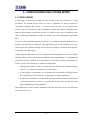
For Multiclock Esterel, the GALS (Globally Asynchronous Locally Synchronous) design
paradigm is adopted. GALS design paradigm is a system in which the more complex bigger
system is divided into smaller single clock islands which are independent of each other and
communicate with each other through synchronizers. Regarding multiclock in Esterel v7, a
new kind of signal called clock is introduced, declared using the clock keyword. Clocks can
only be used to clock registers in classic modules. New clocks can be derived from existing
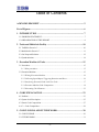
ones using conditional statements and specific clock definition statement. A new multiclock
unit can be declared using the multiclock keyword. It models the GALS system. It has a
header similar to that of a module. In addition, it can declare input and output clocks. The
multiclock body can declare local signals and clocks. It is composed of concurrent elements
that can be as follows:
•
A classic module clocked by an explicitly given clock, which can be an input clock or a
derived clock.
•
A combinational signal computation.
•
Recursively, another multiclock unit instantiated with appropriate bindings for data,
clocks and signals.
Figure 2-1: Multiclock units
- 11 -
•
A clock multiplexer that builds a clock from two other clocks using a signal to select
between them.
Only multiclock units can deal with clocks, while only module units can perform
computations, thus achieving the GALS separation of concerns. Multiclock units can declare
local signals and clocks. They are data-generic exactly in the same way as module units.
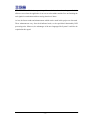
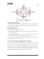
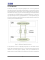
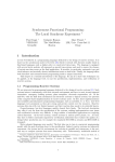
One of the major drawbacks of this multiclock approach is that the generated clock signals,
which are then used to run the various single clocked units, must be derived from a single
“root Clock” which is the source clock of the multiclock unit. Hence there must be some sort
of synchronism between all the existing clocks. A purely asynchronous solution with such
paradigm is not possible.
Figure 2-2: Derived clocks from the MC root clock
2.3 Our Proposed Solution
On the other hand, our proposed solution will intend to implement the tasks in the Esterel v7,
which will then be simulated in the Microsoft Visual C++ 6.0 environment. Basically, the
Esterel Studio v5.3 can generate two types of codes:
1. Code for Simulation: It is useful to run on a PC under an operating system and verify
the behavior of the system .e.g., C/C++/SystemC etc.
2. Code for real-time Execution: It is the end product code duly verified through
simulation and is used to embed on the target machine .e.g., VHDL or VerilogHDL
based circuit models.
- 12 -
We restrict our current goal to the simulation environment in which the generated code can be
used for simulation in languages. The language used for this purpose is C++ and programs are
executed under the Windows operating system. On comparing the C++ based simulation
solution with the conventional multiclock solution, we see that:
1. We get more flexibility to generate independent and totally asynchronous clock. We can
use various tools from simple case statements to the complex interrupt instructions to run
the execution machine. This gives us more variety in the variation of task processing and
the level of asynchronous co-existence that will prevail between the two clocks.
2. These individual tasks can be moved to distant computing units (processors) which
process them under their own conditions like processing speeds, memory resources etc. It
is a perfect example of “processor delegation”. An example of such advantage can be a
synchronous program which needs extensive data/image processing. So this function can
be efficiently achieved with a simple processor along with a DSP processor. During the
normal program execution, task related to intensive data/image processing are delegated
to the DSP processor.
3. In the case of the Multiclock based system, all the singled clocked units must be written in
Esterel language. These units must always be synchronous in nature. But in nature, the
problem is that at times, the synchronous approach is the worst approach to be used. A
better example can be of high amount data transfer or image processing. Our tasking
solution again gives us an edge in terms, that we can literally use any language from C++
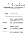
Figure 2-3: Simple Clock patterns
- 13 -
to assembly or java, to write our task programs. This gives us the huge flexibility as most
DSP processors are programmed in C or assembly language. For the simplicity of our
destination goal, we just restrict ourselves now to the synchronous clock paradigm. This
can later on be extended to distributed asynchronous solutions. So for now on, we use the
clock patterns as shown in Figure 2-3: Simple Clock patterns.
4. The Multiclock based approach gives us the advantage to formally verify the source-code
using the SAT property verification tool, for instance.
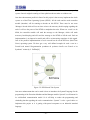
2.4 Synchronization
If the tasks are running at highly different clock speeds or are asynchronous, then for their
effective in-between communication a synchronizer unit will be needed. This unit must ensure
no loss of data and a finite time response. This synchronization unit may also be programmed
in Esterel. The detailed discussions on the synchronization issues are in Ran Ginosar’s paper
[5]. Various types of signals and their relationships are discussed in the paper published by
Messerschmitt [6]. These definitions will help us to better describe our synchronization
problems. The request/acknowledge based design given in the paper is effectively
implemented in the Esterel Studio 5.3’s examples. On the other hand, one can also write the
synchronization unit in some low level language which will be more efficient and robust.
Another solution to the synchronization problems can be the use of dual FIFOs. These FIFOs
can buffer data and are more effective in cases where the clock frequencies don’t differ too
much and the data rate is not too high. This solution is faster in response than the one with
request/acknowledge but is open to data loss. A dual channel FIFO is also implemented in the
Esterel Studio 5.3 examples section.
Figure 2-4: Synchronizer Utilization Example
- 14 -
3 - Execution Machine & Tasks
In this chapter, firstly we present a brief introduction to procedures and host procedures
which are essentially used in the program source code. Then we explain in detail the
execution machine, how it is implemented and what are the different code components.
Finally, we will discuss the Clock Generation method which is an important part of our
custom built execution machine.
3.1 Procedures
A procedure has a list of in, out, and inout arguments, with types annotated using the
corresponding keyword. The procedure is supposed to be executed instantaneously. When
executed, it reads its in and inout arguments and modifies (side-effects) its out and inout
arguments, which must be variables. There are host procedures and generic procedures.
3.1.1 Host procedures
A host procedure is a procedure whose body is defined externally in the host language and
unknown at Esterel level. The arguments and result types cannot be generic; they must be
primitive or declared beforehand. A host procedure is declared using the host keyword:
host procedure UpdateTime ( inout Time , in integer );
Firstly, the C++ model to execute the Code requires the basic understanding of the Execution
Machine.
3.2 Execution Machine
A (real-time) controller is both a “reactive kernel” and an “interface driver”. An effective,
efficient, and dependable cooperation between the reactive code and the environment to be
controlled needs special supports. We call “execution machine” for a synchronous program an
executable architecture that supports this cooperation. The main functionalities of an
execution machine are
1. Acquisition from sensors and construction of the input image of the process to be
controlled,
2. Execution of reactions specified by the synchronous program or chart,
3. Actuation from the output image generated by the reaction. Of course, all these operations
must be done in a timely manner, and the overall behavior must be consistent with the
synchronous hypotheses.
- 15 -
Figure 3-1: A Typical execution machine
3.2.1 Writing Execution Machine
An execution machine allows us to execute “Reactive Kernel” (source code generated by
Esterel compiler) inside our system. Both our generated code and execution machine are the
main components of the application.
Execution Machine Types
We can create two types of execution machines:
•
Event-driven Execution Machine -
The reaction function is called every time an input event
is received by the model.
•
Clock-driven Execution Machine -
The reaction is called periodically (using a timer or a
specific signal) and the input event is stored until the reaction occurs.
For our case, we shall use the Clock-driven Execution machine in which the Esterel program
gets the regular ticks based on an external clock.
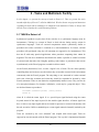
3.2.2 Collecting Input/Output, Triggering Reactions and Reset
The structure of the execution machine is dependant on the application. However, the main
rule of the execution machine is to repetitively call the reaction function. Inputs are read
before each call to the reaction function that generates outputs (when outputs are to be
generated). The general structure of the execution machine is illustrated in Figure 3-2:
Execution Machine Cycle. It is useful to call one instance of the reaction function before calling
any input C function in order to perform instantaneous initial statements.
- 16 -
Figure 3-2: Execution Machine Cycle
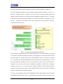
3.2.3 Interfacing Generated Code with User Code
The main types of functions listed in the table below are used to write the execution machine.
Figure 3-3: Generated and user code functions
The C++ based Reactive Kernel consists of the Class implementation. The Esterel Module
generated into C++ source code contains the constructor and the destructor functions which
are to be implemented by the user if needed. The destructor is defined as a virtual function
and it is to be overloaded in the external C++ file. These functions can be used for special
tasks as allocation/de-allocation of memory and initializations of variables etc.
As we can see in the following diagram, all the input functions are preceded by the ‘I_’
whereas the output functions are preceded by the ‘O_’ prefixes. If the Esterel module uses
valued input signals, then the prefix used is ‘IV_’ and its implementation is the responsibility
of the user as its defined as virtual function. All other input functions are implemented in the
reactive kernel and the user only needs to call those functions just before the reaction tick to
show presence of the input. The output functions are all virtual and hence to be implemented
- 17 -
by the user. In both the cases, special care is to be taken regarding the signature of the
functions implemented. All these details are given in the Esterel Studio User Manual [7].
Two other functions defined are of the Automation engine functions and they are the reset ( )
and run ( ) functions. Reset ( ) function is the one used to reset all the inputs/outputs and
internal variables and must be called once before launching the program. The run ( ) function
is the reaction function and may be bonded to an external clock source or stimulus. This way
the run ( ) function will be called on each clock instant and will be equivalent to giving a
clock tick to the Esterel code.
Figure 3-4: Typical Execution Machine Functions
In our proposed solution, each time the Execution Machine is run, a local database is checked
to run all the tasks that are already launched. So, what happens on each reaction instant is that
firstly the Inputs are scanned, then the Execution Machine is given a reaction tick using the
run ( ) statement. The Execution Machine then decides itself to get the valued inputs or to call
the output functions provided by the user to generate the results. Lastly, the task status is
checked to know which tasks must be launched, suspended or killed. This mechanism
continues each cycle. As we know that the original working of the Execution Machine
consists of only the first three steps, we have introduced the last step of task status checking to
effectively implement the tasking mechanism.
As we are not running the tasks on the distributed systems and currently the tasks and the
main module share the same resource, we run the active tasks on the reaction cycle only. This
- 18 -
Figure 3-5: Execution Machine with tasks
process of running the task will be moved to the remote machine in case of distributed design
and the main module will only issue the commands. When the task finishes, the return signal
will be given to the Execution Machine which will in turn update its task status database.
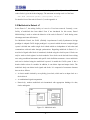
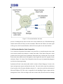
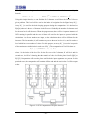
3.2.4 Execution Machine Code Composition
Let us look into the problem from another view point. Here we consider that the tasks reside
on the remote machine also and there is another unit called ‘Clock Pattern Generator’ which
generates the clock signal for the Synchronous Kernel and also for all the tasks. The only link
between the tasks and the kernel is through the control signals like start, kill, suspend, resume
and return. Figure 3-6: System Code Composition shows the types of programming languages
used in the system programming.
Synchronous Kernel is the main module which is written in Esterel language. It reacts to the
inputs and generates outputs and launches the tasks. The code which wraps the synchronous
kernel consists of the Execution Machine written in C++ and works under the environment of
Microsoft Windows XP. This code is responsible for the handling of inputs, outputs and the
management of tasks. Here one thing to take into account is that, the tasks must not exchange
- 19 -
data directly with the Synchronous Kernel. All sorts of communication will take place
through the User written code.
Figure 3-6: System Code Composition
Tasks can be written in any language either synchronous as Esterel or conventional one like
C/C++. This provides the real advantage obtained from using the tasking mechanism in this
approach. The necessary condition to be fulfilled is that the task code must not be ‘blocking’
and each execution block must act as a finite state machine. By the term blocking we mean
that the code must terminate in finite amount of time, comparatively much smaller than the
time period of the Execution Machine, as it is to be called after each period duration. This
hypothesis is easy to implement for the synchronous tasks but for the non-synchronous tasks
written in conventional languages, the code must be broken apart into small pieces of
execution. This can be done using the switch cases in the C/C++ language easily. Here is an
example below:
Void XYZ ( state ) {
switch ( state ){
case 1:
…….
break;
- 20 -
case 2:
…….
break;
default:
…….
break;
}
}
A static variable is defined and is used to point to a chunk of code. Before exiting the routine,
this variable is updated so that it may point to the next code chunk on the next call to the
routine. This is the conventional way of writing the code but there can be other methods also
which also lead us to non-blocking codes. All such methods also depend on the type of
algorithm used. One such example of a task calculating GCD in C language is given next. In
this example we take two inputs a and b and return the output g for the GCD value. We define
internal static variables as mirror of the inputs. These variables are updated with the input
values only once at the start of the program using the first_time variable. Code is written in
such a way that each time the program is called, it does a small amount of calculation. This
continues until finally we get the output upon which we set the ‘finished’ flag and reset the
first_time variable so that the new computation can be effective on next call. Also the value of
the by-reference parameter (g) is updated here. Note that this approach is only necessary to
mimic the behavior of the synchronous hypothesis by a non-synchronous language and it is
not necessary to program in this way.
void gcd (int *ig, int ia, int ib)
{
static int true_g, true_a, true_b;
int g, a, b;
if (first_time = = 1)
{
true_g = *ig;
true_a = ia;
true_b = ib;
first_time = 0;
finished = 0;
}
g = true_g;
a = true_a;
b = true_b;
- 21 -
if(b != 0 && finished != 1)
{
g = a % b;
a = b;
b = g;
}
else
{
*ig = a;
finished = 1;
first_time = 1;
}
true_g = g;
true_a = a;
true_b = b;
// Generate return signal to the Synchronous Kernel
}
3.2.5 Generating Clock Patterns
Referring back to the diagram Figure 3-6: System Code Composition, the last part to mention
is the ‘Clock Pattern Generator’ unit. This unit can be written either in synchronous language
like Esterel or in any conventional language like C/C++ or may also be implemented as
hardware circuit. The function of this unit is to provide the clock pulses to all the modules
present in the system. These generated clocks can be totally asynchronous. The clock patterns
generated can be very specialized also. We can add the padding bits at the start of the clock
patterns also like
0100111011 (0110)*
This means that for the first time during the initialization, the specific pattern is generated and
then the clock starts to act periodically. There can be many other such examples. These
programs can be easily written in the synchronous languages like Esterel.
On each clock edge, the synchronous kernel and the tasks will be given a reaction tick. This
can be easily done for the Esterel generated programs by calling the run () function. For the
non Esterel compiler generated source codes, we can use some sort of await command which
waits for the clock edge. Upon receiving the clock edge, it performs the action and then again
goes into the await state. This feature of customized clock sources gives these tasks another
edge over the conventional multiclock based modules.
- 22 -
4 - CODE EXPLANATION
In this chapter, we present the examples and their detailed explanation to help us understand
better what we have studied till now. The chapter begins with the introduction to a sample
problem of GCD and its technical details. Then we illustrate the way processing takes place
with the help of a sequence diagrams. Finally, we briefly explain the code for both the Esterel
and C++ languages.
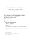
4.1 Problem
For our test problem, we use a GCD (Greatest Common Divisor) calculation mechanism
which will take in several input numbers and their GCD will be calculated in such a way that
as soon as any two numbers are relatively prime to each other, we shall stop further
computation and return 1 for the GCD. This method is illustrated in the diagram below:
Figure 4-1: Parallel GCD Computation
In this particular example, five numbers are input and their GCD is to be calculated. Our
solution to the problem consists of a GCD calculation routine which takes two arguments as
input and gives the result. Several instances of this routine are run in parallel and in case of
odd number of input numbers, the last input will be passed to the next stage in the calculation
tree. In this fashion, the odd number of inputs will reduce to even ones at one future stage.
- 23 -
The depth of this tree logic can be calculated based on the number of elements used by the
formula:
level = n + 1
where 2n-1 < number of elements < 2n
Using this simple formula, we can find that for 5 elements we will have the level of 4 for our
given problem. This level will be used as the index of navigation for the Signal array B [ ].
Array B [ ] is used for the book keeping purpose during the computation. It is declared as
B[n][n] where n is the no. of elements in the first row. Gradually the number of elements used
for the next levels will decrease. When the program runs, there will be 4 separate instances of
GCD running in parallel and the two of them will wait for the inputs to proceed with the
calculations. As diverse numbers are input, so the calculation times will be different for the
instances. The last number (6) will continue to pass to the next level as it is, until it reaches a
level which has even number of values. For this purpose, an array N [ ] is used to keep track
of the maximum variable index in each row of B [ ]. The computation of N will be done as:
N[ i ] = (elements - 1) / ( 2i )
where i is the index of the level. So for the first row with 5 elements, N will be 4 and for
second row, it will be 2 showing that the transfer of value 6 will take place from B [0][4] to
B[1][2]. Computation will not take place until both the input arguments are present. In this
particular case, the computation will continue till the end and the result value 3 will be output
at last.
Figure 4-2: GCD Computation with quick abortion
- 24 -
But considering another case in which we have the numbers which are relatively prime and
we must stop the computation of the other numbers as soon as we get the relatively prime
results from one instance. Tree diagram for this particular case is given in Figure 4-2: GCD
Computation with quick abortion.
This is a valuable example for the possible cases of critical applications in which same
computation is being performed on several processors in parallel and the first result coming
from one computation halts others. Note here for the case of even number of input signals like
4. In that case, there is no need to transfer the value of the last element to the next level, as all
the elements will make pairs for the GCD computation. So we use the following conditional
statement to bypass the last element transfer to next level,
(elements - 2 * (elements / 2)) > 0
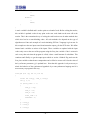
4.2 System level Description
To better understand the functioning of the algorithm, we use the UML Sequence diagram in
Figure 4-3: UML System Sequence Diagram. In the diagram, we show the system calls from
one function to another. So, by proceeding in an order, we first create an instance GCDS of
the gcds synchronous kernel class. This instance is then reset and the full input signals are
called. After giving the inputs, we give a tick to the kernel. The inputs are stored to internal
buffer array and no visible change appears for the tick.
Then we give the GCDS instance another tick. This time the code for the two nested for loops
starts. The outer loop has four parallel executing instances, one for each level and each of
these instances contains five more instances, one for each element (see Esterel v7 Program
Code for details). Inside the inner loop, we have got an if statement to filter out the invalid
combination of indices i and j. So for the current problem with five elements, we have four
GCD computation instances running in parallel. Two of these instances are at the first level
and start the computation directly when they are instantiated whereas the other two wait for
the results from the upper levels to start computation. Hence, when the GCDS instance takes a
tick, the gcds_start_TASK ( ) procedure is called for the first instance. This procedure is
provided with the input values and the value for the instance number field is given with ‘-1’.
This is a sort of predefined protocol telling the C++ program that the instance call is a new
one and must be assigned with an ID. We use a variable in the corresponding class of the task
to keep track of the instances. After this, an instance for the rgcd module is created, reset and
finally given a tick.
- 25 -
Figure 4-3: UML System Sequence Diagram
- 26 -
This tick to the rgcd module enables the code to pass through the await immediate A & B
instructions, as both A & B are present at very first moment. The next instruction is
immediately executed in the same instance and the next procedure call is made. This
procedure call creates a new instance to the lowest level gcd module which will compute the
GCD. The same thing is repeated with the second instance but for the third and the forth
instance, the values of A and B are awaited for and hence the procedure rgcd_start_TASK( )
doesn’t start.
When the rgcd module intends to pass a value to the gcd module, it doesn’t pass it directly. It
first sends the values to the execution machine which stores them and after that the values are
passed to the gcd module. So in the sequence diagram, we show it in a way that the gcd
module takes values form the main module. All this procedure continues until we get the
result from at least one GCD pair. On its output, an internal signal “task_terminated” is set to
1. This is then used to signal the parent module and return the value.
4.3 Esterel Code Composition
The Esterel v7 code for the given problem is given in the Appendix-B. It consists of the
following modules with their input/output signal skeleton as:
•
main module gcds:
input A [elements] : unsigned;
output G : unsigned;
•
module rgcd:
input {a,b}: unsigned;
output g:unsigned;
output relativeprime; gcd.strl
•
module gcd:
input {a,b} : value unsigned;
output g : unsigned;
The most complex part of the code consists of gcds module which mimics the above
described behavior of the parallel tree based computation. The module contains an input
signal array A[ ] with the size of the number of elements and an output signal G which will
contain 1 if at least any of the two given numbers are relatively prime else will contain the
GCD of all the numbers. The task definition consists of host procedure which has the
following definition:
- 27 -
host procedure gcds_start_TASK (in string, inout integer, inout bool,
inout unsigned, in unsigned, in bool, in unsigned, in bool, in bool,
in bool, out bool);
This procedure is called from the Esterel module and will be implemented in C++ or any
other host language. The in, inout and out are the direction identifiers with respect to the
procedure and act as input for the in and as pointer for the inout and out identifiers. Task
declaration also consists of the constant definition as follows:
constant task_rgcd : string = "rgcd";
which is used to input the name of the task being called. This is only to easily differentiate the
names of the various tasks.
The gcd module consists of the code which takes two input numbers and gives the resultant
GCD of those numbers. This gcd module is instantiated inside the rgcd module along with the
code that waits first for the two inputs a and b. When the gcd module returns the result to the
rgcd, it then checks the gcd to be equal to 1, upon which it outputs the relativeprime signal.
The gcds module uses the nested for loops of indices i and j to call the several instances of the
rgcd module. In the current example, there are four instances of rgcd that run in parallel. Two
of these instances go to direct processing of GCD whereas the other two wait for the inputs.
Due to the use of abort statement, at any level when the relativeprime signal becomes true, the
program is terminated.
The procedure call to the rgcd is made with the local variables used to get the return values.
We know that the procedures don’t allow the signals to be used as procedure outputs. Hence,
variables are used as containers to get the values back from the procedure calls. These
variables are declared in such a way that their instance is created just before procedure call
and then after the procedure call, the value of the variable is passed to a signal and it finishes
itself. All this is done to avoid the sharing of variables between various instances which is an
access violation error.
4.4 C++ Code Composition
The above three Esterel files when used to generate C++ code give us two header files and
one Cpp file for all the modules. For the gcds.strl file, the files generated are the gcds_class.h,
gcds_strl.h and gcds.cpp. this is the same for the other files also. One thing to note here is that
the rgcd and gcds modules use the procedure calls, so we have to create the header file like
gcds_data.h for the gcds module, which will have the signature for the procedure being used.
- 28 -
This header file is included by the generated C++ code. Note that we have to introduce two
more files named the bignum.c and the bignum_fct.h which are used by the generated C/C++
code if the Esterel program contains arithmetical calculations.
The core of the C++ code is the file gcds_MAIN.cpp which implements the Execution
Machine, the Clock Generator and the object instances of the tasks. This whole setup roughly
consists of the following main parts:
•
TASK HANDLING FUNCTIONS (BACK-END)
•
TASK EXECUTION FUNCTIONS (FRONT-END)
•
INPUT / OUTPUT FUNCTIONS
•
MAIN SIMULATION ROUTINE
The back-end task handling functions are basically the classes that are used to create the
instances of the tasks classes through the start ( ) function and then also are used to
manipulate them through the functions like kill ( ), suspend ( ) and resume ( ). As our present
working model consists of the tasks running on the same machine as the Synchronous Kernel,
so the run ( ) routine is also present in this class. These routines are called for each object
which is manipulated. One thing to note here is that, these classes only act as the manager of
the task classes and their only one instance exists. These manager classes are initialized at the
start of the program initialization.
The front-end task handling functions consist of simply the procedure routines that are being
called from the Esterel generated code. These routines take decision based on the input
parameters. Firstly they decide that the task being called is valid or not. Then the task instance
number is checked. If the number shown is -1, then it means that the task instance was not
created at the previous call and it is to be created now. Then this created instance is assigned a
unique ID number which is returned also. The next time this procedure is to be called, it sends
this ID number for the identification of the procedure. If the procedure was already created,
then the input parameters are judged to call the appropriate routine from the back-end
functions.
The I/O functions have almost the same implementation rules as for previous versions. All the
outputs and the valued inputs must be associated with a user defined function to transfer the
data. The Main routine consists of the code which initializes an instance of the synchronous
kernel. This instance is then called on each reaction tick. It is to be noted that all the nonvalued inputs must be called by the user if they are to be shown present, before the reaction
tick of the Synchronous kernel using the run ( ) command.
- 29 -
5 - CONCLUSIONS AND FUTURE WORK
5.1 CONCLUSIONS
In this report we discussed the theory and the creation of the tasks in Esterel v7 using
procedures. We studied that the tasks are used to implement the lasting activities in
synchronous languages like Esterel v7. For some types of tasks, we can consider their
behavior just as the execution of some synchronous program but running at different speeds
than the main program (synchronous kernel). So when the tasks can be considered as the
series of individual independent reactions, we can have two vital complementary approaches
for it.
We can use the multiclock approach of Esterel v7 in which the tasks are implemented as
modules with the clocks driving them. This approach has got several advantages of its own
like we can use the simulation facility and we can use the property verification tools like SAT
to formally verify the program.
Another approach that can be used is to compile the Esterel program to some other flexible
language where it can be used to develop dedicated “Execution Machines” to implement the
original Esterel task semantics. Such mechanism is built on the structure and principle of
Esterel v5 tasks. This solution gives us many advantages like:
•
More general solution: we get a very general solution. We have got a flexible language
like C/C++ to workout our problems in a better fashion.
•
Various degrees of asynchrony: we can generate the clock patterns as desired and can
have the different levels of relatively asynchronous execution of programs.
•
Possibility of distribution: we can shift the execution of tasks from the local machines
to the remote processors, which is very useful like in cases where one task may need
high computation processing demands.
This method can be used to run the synchronous tasks like in Esterel as well as asynchronous
tasks written in C or C++.
- 30 -
5.2 FUTURE WORK
For the future, we have got several options regarding the tasks. As we have generated the
tasks which reside on the same machine as the main module, we can try to achieve diversity
by transferring the tasks to remote machines. The only commands that will be issued from the
main module will be of start, stop, pause, resume and to kill the task. The destination machine
can be any thing from a full fledged computer to an embedded DSP processor. To achieve this
target, the knowledge of socket or pipe implementation in C++ will be important. Pipes will
be used for the inter-process communication on the local machine whereas the sockets will be
used for the processes on different machines.
Figure 5-1: Distributed Computing Tasks System
In this phenomenon of work, an independent program has to be made which will work
directly under the operating system and will act as the liaison between the tasks and the
controller. We can call this program as ‘Manager’. In the case of distributed tasks, this
manager must have the parts running on all the machines and will make the communication
- 31 -
possible. The beauty of this approach is that, the tasks can reside even on any operating
system. One task might be running on Linux platform whereas other on windows one.
One other enhancement possible in future for this project is that we may implement the whole
system on a Real-Time Operating System (RTOS). All the tasks and the main controller
module (launcher) will be running as threads on this RTOS. There must be one more
‘Manager’ thread which will run at times to have the necessary book-keeping regarding the
tasks. It will use the power of the RTOS to manipulate the tasks. When ever a task is to be
killed, the controller module will send the message to the Manager, which will make
necessary book-keeping and will send the message to the RTOS to kill the task. Such an
implementation is an impressive model and will be an interesting experience in this regard.
One of the possible implementations of such a model can be on the RTLinux (Real-Time
Linux) operating system. We have got a very well defined example for such a case in a
French book named “Programmation synchrone de systèmes réactifs avec Esterel et les
Syncharts” written by L. Zaffalon[8].
Figure 5-2: RTOS based Task System
One more enhancement that can be made is that we introduce the SystemC language for the
programming of the Execution Machine and the Manager module. SystemC is well-known for
its well-defined communication model. So it will help to reduce the programming and
scheduling burden regarding the tasks communication. SystemC is also a good choice to
implement this project as it is getting wide-spread acceptance as an industrial standard
language.
- 32 -
One last idea for future progress can be to use the tasking mechanism on the DSP processors.
DSP processors are well-known for their high speed performance in the case of data and
image processing. So we can implement such a synchronous system which at one stage needs
to do intensive image processing. For this purpose, the synchronous program can launch the
task for image processing residing on the DSP processor. When the job finishes, this task will
return the result to the main synchronous module.
- 33 -
APPENDIX A:
Tasks in Esterel v5
This section gives a detailed overview of the tasks concepts, semantics and low level details
in Esterel v5. Firstly, we introduce the task semantics and the effect of various synchronous
statements on the behavior of tasks. Then, we will discuss the low level details of the
corresponding C code for the tasks generated by Esterel compiler. At this point, ExecStatus.h
file will also be discussed as being the key concept. Lastly, we will overview the functions
that are to be implemented by the user to manipulate the tasks.
When an “exec TASK return R” statement starts, it signals to its environment that a fresh
instance of the task T should start with parameters passed by reference and value just as for
procedures. The signaling is instantaneous. The Esterel program does not wait for the task and
continues reacting autonomously. More precisely, the thread that has started the exec
statements waits for task completion, but the other threads continue reacting to inputs. In
some instant in the strict future of the starting instant, the environment signals back task
completion to the Esterel program by sending the return signal R. Within the Esterel program,
receiving R provokes instantaneous update of reference arguments according to the values
returned by the task and instantaneous termination of the exec statement. During its execution,
an exec statement can be suspended or aborted. This is signaled to the external task by
sending appropriate suspension and abortion signals. The task launching and signaling
implementation mechanism entirely depends on the compiler and run-time system. The only
implementation constraint is to respect the Esterel logical view. Uniqueness of Return Signals
One may have several exec statements for a given task T; therefore, one may also have
different concurrent instances of the same task in the environment. The return signal is used to
tell the Esterel program which instance has terminated. For this to be possible, return signals
must uniquely identify exec statements. Hence, no two exec statements in a program can have
the same return signal.
As any other Esterel statement, an exec statement is subject to abortion by abort, weak abort,
or trap statements and to suspension by suspend statements. The simplest case of abortion is
the weak one. Consider the example:
weak abort
exec TASK (X) (1) return R;
when I
- 34 -
In the first instant, the task is started. Then, the behavior is as follows:
•
If R occurs before I or if R and I occur simultaneously, then X is updated and the whole
weak abort statement terminates.
•
If I occurs before R, then execution of TASK is aborted and the external task is aborted.
There is no update of X.
Strong abortion is a little bit more delicate. Consider the example:
abort
exec TASK (X) (1) return R;
when I
After starting the task in the first instant, the behavior is as follows:
•
If R occurs before I, then X is updated and the whole abort statement terminates.
•
If I occurs before R, then execution of TASK is aborted and the external task is aborted.
There is no update of X.
•
If I and R occur simultaneously, then the abort statement terminates. Although the task did
terminate, X is not updated since the body of the abort statement does not receive control.
No abort signal is sent to the task either since it is terminated.
For the case of Suspension of exec Statements as in the following program:
suspend
exec TASK (X) () return R
when S
When S occurs after the starting instant, the exec statement is suspended. This is signaled to
the environment by sending an implementation-dependent suspension signal. The signal is
sent in every instant where the exec statement is suspended. Termination of the exec
statement can occur only when that statement is active. Assume that R and S occur
simultaneously. Then, R does not provoke termination of the exec statement and its
occurrence is lost. It is the environment’s responsibility to sustain R until the exec statement
is not suspended any more, which is easy using the abort and suspend signaling mechanism.
If needed, it is easy for the execution environment to convert the suspension information
available in each instant from the Esterel program into suspend-resume information that may
be handier for operating systems.
- 35 -
A typical use of the multiple exec statement is to try several ways to perform a given
computation in parallel, stopping when the first computation is done:
exec
case InvertMethod1 (Matrix) () return R1
case InvertMethod2 (Matrix) () return R2
case InvertMethod3 (Matrix) () return R3
end exec
All necessary bookkeeping is nicely performed by the Esterel compiler.
ESTEREL TASK HANDLING AND GENERATED C CODE:
Now we discuss the interface of the C code generated by the Esterel compiler for an exec
statement. This code reflects concretely the way tasks are handled abstractly in Esterel. It is
organized in two layers. The low-level layer is a direct interface to run-time C data structures
that contain all the required information about the status of exec statements. The optional
higher-level layer provides the user with a functional interface. The design might look heavy
at first glance, but it intends to provide the user with maximal flexibility with respect to actual
task handling. The functional interface is reasonably simple, but not fully general since other
ways of interfacing exec statements can be thought of, in particular as far as task suspension is
concerned. The low-level interface is meant to be convenient for any user who wants to
design its own fine-grain task handling. Notice that we do not provide the user with an actual
asynchronous task handling interface, because this is highly dependent on particular operating
systems.
Low-level Layer: the ExecStatus Interface
We assume that the main module is called PROG. The following C function returns the
number of exec statements in the compiled program:
int PROG_number_of_execs ();
The following C function returns the number of exec statements associated with a task of
name TASK in the compiled program:
int PROG_number_of_execs_of_TASK ();
The ExecStatus Structure:
Each exec statement, which is uniquely identified by its return signal, is associated with a C
structure of type ExecStatus that contains all relevant information about the exec status just
after a reaction. This structure can be recovered in three ways:
- 36 -
•
by name: for each exec of return signal R, the generated C code contains a variable PROG
exec status R declared by:
ExecStatus PROG exec_status_R = ... ;
•
by absolute number: the generated code declares an array of pointers to the ExecStatus
variables, of size PROG number of execs(), which has one entry for each exec statement:
ExecStatus *PROG exec_status_array [] = ... ;
•
by relative number: for each task TASK, the generated code contains an array of pointers
to the ExecStatus variables, with one entry for each exec of that task. The size of the array
is given by the function PROG number of execs of TASK():
ExecStatus *PROG exec_status_array_of_TASK[] = ... ;
Here is the definition of the __ExecStatus structure:
typedef struct
{
unsigned int start : 1 ;
unsigned int kill : 1 ;
unsigned int active : 1 ;
unsigned int suspended : 1 ;
unsigned int prev_active : 1 ;
unsigned int prev_suspended : 1 ;
unsigned int exec_index;
unsigned int task_exec_index;
void (*pStart)(); /* takes a function as argument */
int (*pRet)(); /* may take a value as argument */
} __ExecStatus;
The meaning of these fields is as follows:
•
start has value 1 if and only if the exec statement starts and is not immediately killed. In
that case, a new instance of the task code should be started in the current instant. See
below for how to recover the actual parameter values using the pStart field.
•
kill has value 1 if and only if the exec statement is killed in the current instant. Then, the
currently running instance of the task should be killed; notice that kill can only be 1 if
there is such a running instance.
•
active has value 1 if and only if the exec statement is active in the current instant; this
means that the exec is started in the current instant or has been started before, has not yet
been killed, and that the task code has not yet returned.
- 37 -
•
suspended has value 1 if and only if the exec statement is active and suspended in the
current instant by an enclosing suspend statement.
•
prev active has value 1 if the exec was already active in the previous Esterel instant.
•
prev suspended has value 1 if the exec was suspended in the previous instant.
•
exec_index an integer index identifying uniquely the exec statement. This index ranges
between 0 and n - 1 if the Esterel program contains n exec statements after full
submodule instantiation.
•
task_exec_index an integer index identifying uniquely the exec statement among those
referring to the same task. This index ranges between 0 and p - 1 if the Esterel program
contains p exec statements for this task after full submodule instantiation.
•
pStart an auxiliary function pointer to be used at start time, i.e. when start is 1. See details
below.
•
pRet a pointer to the return function PROG I R associated with the return signal, if the
name of the main module is PROG and the name of the return signal is R (remember that
a return signal is just a particular input signal). See details below.
The function pointed to by pStart takes a user-provided function as argument, and the
reference and value arguments are passed to this user function with the same convention as
for a procedure (reference arguments as pointers, value arguments as values). A typical use is
if (exec_status.start)
(*exec_status.pStart) (my_start);
This will call the user-provided function my start with arguments the arguments of the task at
start time. The user-provided function my start should perform two actions: effectively
starting the task in the environment, and saving the pointers to the reference arguments for
their update at return time, see below.
Calling the (*pRet) or PROG_I_R function in the master code amounts to emitting R, hence
to signal to Esterel that the task is completed. The return function takes a value if and only if
the return signal carries a value; then the value passed becomes that of the return signal. The
return function can be called either directly using its full name PROG_I_R or indirectly
through the pRet pointer. When the return function is called, the locations pointed by the
pointers passed at start time for reference arguments are supposed to contain the values
updated by the task.
- 38 -
Notice that there are redundancies between the fields of ExecStatus. For example, prev active
and prev suspended could be computed directly by the user. However, we chose to include
these informations since they are very easy to compute from within Esterel and very handy for
the user.
Reincarnation of exec Statements:
Notice that an exec statement can be killed and restarted in the same instant, for example by
executing the following:
loop
exec T(...)(...) return R
each I
In this case, when I occurs, there may be two active occurrences of the task code that the user
has to manage properly. The first one is the one being killed, the second one is the one being
started. There can be no more that these two occurrences.
Handling Reference Arguments
Let us give more details on the handling of reference arguments. Consider an Esterel variable
X implemented as a C variable of location X, and assume that X is passed by reference in an
exec statement.
At starting time, the contents of X are copied into another location L whose address is passed
to the user starting function my start. During task execution, the user may freely modify the
contents of L. At return time, i.e. when PROG I R or equivalently (*pRet) and then PROG are
called, the contents of L are automatically copied back to location X.
This copy-restore mechanism is made necessary by the possibility of killing exec statements:
if reference arguments could be modified in place at location X before an exec gets killed, the
value of X would change in the Esterel program, which is forbidden by the Esterel semantics.
Update of reference arguments must be performed in place in the location L passed to the user
starting function my start; this is why these pointers should be saved by my start. Actual
update of X by L is triggered only when the automaton PROG is called with return signal R
present (and of course only if the exec statement is not killed by an enclosing abortion
statement).
- 39 -
The Functional Interface to Tasks
We now describe the much simpler functional interface. The user should provide four C
functions:
•
A user start function to start the task. This function receives the reference and value
parameters plus a pointer to the ExecStatus record of the exec statement as the last
parameter; this is useful to index process-id tables associated with asynchronously
running operating systems tasks, using the exec index fields.
•
A kill function that is called when a task is killed, with a pointer to the ExecStatus
structure as argument.
•
A suspend function that is called when the task becomes suspended, i.e. is now suspended
but was not suspended in the previous instant (suspended=1, prev suspended=0). This
function also receives a pointer to the ExecStatus structure as argument.
•
A resume function that is called when the task should resume, i.e. when it was suspended
at previous instance and it is neither suspended nor killed in the current instant. This
function also receives a pointer to the ExecStatus structure as argument.
To use the functional interface, one simply has to write a call to a specific STD EXEC library
macro with arguments the return signal name and the user functions, this for each exec and
right after each call to the automaton:
#include "exec_status.h"
my_start () { ... }
my_kill () { ... }
my_suspend () { ... }
my_resume () { ... }
...
PROG(); /* perform a transition */
STD
EXEC
(R1,
PROG,
my_start_1,
my_kill_1,
my_suspend_1,
(R2,
PROG,
my_start_2,
my_kill_2,
my_suspend_2,
my_resume_1);
STD
EXEC
my_resume_2);
A special DUMMY function can be used if a user function is not necessary, for instance if
there is no suspend statement in the Esterel program:
STD EXEC (R2, PROG, my_start_2, my_kill_2, __DUMMY__, __DUMMY__);
- 40 -
Finally, one can also write
STD
EXEC_FOR_TASK
(TASK,
PROG,
my_start,
my_resume);
This calls STD EXEC for all return signals of task TASK.
- 41 -
my_kill,my_suspend,
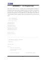
APPENDIX B:
Esterel v7 Program Code
This section consists of the program code written in Esterel v7 for computing multiple GCDs
in parallel. The programs for the three modules gcds, rgcd and gcd are given in order. Further
code explanations are given in the relevant topics.
// file: gcds.strl
// author: Aamir Mehmood
// date: May 29, 2006
main module gcds:
constant elements : unsigned = 9;
constant level : unsigned = 5;
// level = n + 1, where 2^n = range for
elements.
input A[elements] : unsigned;
output G : unsigned;
// gcds_start_TASK ("rgcd", -1/Inst_No, rp, ig, ?a, presence(a), ?b,
presence(b), ?S, ?K, r)
host procedure gcds_start_TASK (in string, inout integer, inout bool, inout
unsigned,
in unsigned, in bool, in unsigned, in bool, in bool, in bool, out bool);
constant task_rgcd : string = "rgcd";
signal
relativePrime,
N[level] : unsigned init 0,
B[level][elements] : reg unsigned init 0,
R[level][elements] : bool
in
for i < level dopar
emit ?N[i] <= (elements - 1)/(2**i)
end for;
emit next ?B[0] <= ?A;
pause;
weak abort
for i < (level - 1) dopar
emit next ?B[i][?N[i]] <= ?B[0][?N[0]] if (elements - 2 *
(elements / 2)) > 0;
for j < elements / 2 dopar
- 42 -
if j < (?N[i] + 1) / 2 then
var task_inst : integer := -1 in
weak abort
// Launch the TASK rgcd
always
var {rp,r,a_pres,b_pres} : bool := '0, g :
unsigned in
a_pres :=
mux(B[i][2*j], '1,'0);
b_pres :=
mux(B[i][2*j+1], '1,'0);
call gcds_start_TASK (task_rgcd,
task_inst, rp, g, ?B[i][2*j], a_pres,
?B[i][2*j+1], b_pres, '0, '0, r);
emit {
relativePrime if rp,
next ?B[i+1][j] <= g if r,
?R[i+1][j] <= r}
end var
end always
when ( ?R[i+1][j] = '1)
||
if i < 1 then
emit next {?B[0][2*j] <= ?A[2*j], ?B[0][2*j+1] <=
?A[2*j+1]}
end if;
end var
end if
end for
end for
when relativePrime do
emit ?G <= 1
end abort;
pause;
emit ?G <= ?B[level - 1][0] if not pre(relativePrime)
end signal
end module
- 43 -
// file: rgcd.strl
// author: Aamir Mehmood
// date: May 17, 2006
module rgcd:
input {a,b}: unsigned;
output g:unsigned;
output relativeprime;
host procedure rgcd_start_TASK (in string, inout integer, out unsigned,
in unsigned, in unsigned, in bool, in bool, out bool);
constant task_gcd : string = "gcd";
var task_inst : integer := -1, ig : unsigned := 0, R : bool := '0 in
{await immediate a || await immediate b};
abort
// Launch the TASK gcd
always
call rgcd_start_TASK(task_gcd, task_inst, ig, ?a, ?b, '0, '0, R)
end always
when (R = '1);
emit ?g <= ig;
emit relativeprime if ?g = 1
end var
end module
- 44 -
// file: gcd.strl
// author: Aamir Mehmood
// date: June 6, 2006
module gcd:
input {a,b} : value unsigned;
output g : unsigned;
signal {aa,bb,r} : unsigned in
emit {
?aa <= ?a,
?bb <= ?b,
?r <= 1
};
pause;
abort
sustain
{
?r <= (pre(?aa) mod pre(?bb)),
?aa
<= pre(?bb),
?bb <= ?r
}
when (pre(?bb)=0) do
emit ?g <= pre(?aa)
end abort
end signal
end module
- 45 -
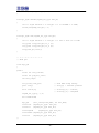
APPENDIX C:
C++ Program Code
This section consists of the C++ program code the Execution Machine consisting of
Synchronous Kernel, tasks and their management routines, I/O functions etc. The programs
are for the three ‘.cpp’ files consisting of gcds_MAIN.cpp, which is the primary, the
gcds_data.h and rgcd_data.h. The two header files are almost identical and contain the
‘Esterel Procedure’ function’s signature. Further code explanations are given in the relevant
topics.
// file: gcds_MAIN.cpp
// author: Aamir Mehmood
// date: June 12, 2006
#include<stdio.h>
#include<conio.h>
#include<string.h>
#include<iostream.h>
#include "gcds_class.h"
#include "rgcd_class.h"
#include "gcd_class.h"
#define tcreate 0
#define tsuspend 1
//
*..*..*..*..*..*..*..*..*..*..*..*..*..*..*..*..*..*..*..*..*..*..*..*..*..
*
// TASK HANDLING FUNCTIONS (BACK-END)
// *..*..*..*..*..*..*..*..*
// TASK rgcd
class mgr_rgcd
{
public:
static int inst_counter;
static int rgcd_inst_count;
int inst_range;
strl_string task_rgcd;
// Task Name using String.
- 46 -
rgcd** array;
// array[n] = instance pointers
bool* status[2];
// status[0][n] = tcreate,
// status[1][n] = tsuspend
unsigned_int_type g, a, b;
boolean a_pres, b_pres, relativeprime;
bool terminated;
mgr_rgcd
(strl_string Task_Name, int Inst_Max);
void start
(signed_int_type* Inst_No);
void kill
(signed_int_type Inst_No);
void suspend
(signed_int_type Inst_No);
void resume (signed_int_type Inst_No);
void run
(signed_int_type Inst_No);
};
int mgr_rgcd::inst_counter = 0;
// Max One instance possible.
int mgr_rgcd::rgcd_inst_count = 0;
static mgr_rgcd the_rgcd_Instance ("rgcd",100);
// ("Task_Name", Inst_Max)
mgr_rgcd::mgr_rgcd(strl_string Task_Name, int Inst_Max)
{
if (++inst_counter <= 1)
{
task_rgcd = Task_Name;
inst_range = Inst_Max;
array= new rgcd * [Inst_Max];
status[tcreate]= new bool [Inst_Max];
status[tsuspend]= new bool [Inst_Max];
for (int n = 0; n < Inst_Max; n++)
{
array[n]= (rgcd *)0;
status[tcreate][n]= 0;
status[tsuspend][n]= 0;
}
}
else
{
cerr << "Internal Error: Only one instance of mgr_rgcd allowed"
<< endl;
exit(1);
}
- 47 -
}
void mgr_rgcd::start(signed_int_type* Inst_No)
{
if (*Inst_No < inst_range)
{
*Inst_No = rgcd_inst_count++;
cout << "New rgcd instance "<< *Inst_No << " started with a = "
<< a << " and b = " << b << endl;
array[*Inst_No] = new rgcd();
array[*Inst_No]->reset();
status[tcreate][*Inst_No] = 1;
}
else
{
cerr << "Internal Error in rgcd start routine: range exceeded("
<< *Inst_No << " > " << inst_range << ")" << endl;
exit(1);
}
}
void mgr_rgcd::kill(signed_int_type Inst_No)
{
if ((Inst_No < inst_range) && (Inst_No >= 0))
{
cout << "rgcd instance "<< Inst_No << " is terminated.\n"
<< endl;
delete array[Inst_No];
status[tcreate][Inst_No] = 0;
}
else
{
cerr << "Internal Error in rgcd kill routine: last instance
already deleted." << endl;
exit(1);
}
}
void mgr_rgcd::suspend(signed_int_type Inst_No)
{
cout << "rgcd instance " << Inst_No << " is suspended." << endl;
- 48 -
status[tsuspend][Inst_No] = 1;
}
void mgr_rgcd::resume(signed_int_type Inst_No)
{
cout << "rgcd instance " << Inst_No << " is resumed." << endl;
status[tsuspend][Inst_No] = 0;
}
void mgr_rgcd::run(signed_int_type Inst_No)
{
cout << "rgcd instance " << Inst_No << " runs a tick.\n" << endl
if(a_pres) array[Inst_No]->I_a (a);
if(b_pres) array[Inst_No]->I_b (b);
array[Inst_No]->run();
}
// *..*..*..*..*..*..*..*..*
// TASK gcd
class mgr_gcd
{
public:
static int inst_counter;
static int gcd_inst_count;
int inst_range;
strl_string task_gcd;
// Task Name using String.
gcd** array;
// array[n] = instance pointers
bool* status[2];
// status[0][n] = tcreate,
// status[1][n] = tsuspend
signed_int_type g, a, b;
bool terminated;
mgr_gcd
(strl_string Task_Name, int Inst_Max);
void start
(signed_int_type* Inst_No);
void kill
(signed_int_type Inst_No);
void suspend
(signed_int_type Inst_No);
void resume (signed_int_type Inst_No);
void run
(signed_int_type Inst_No);
};
- 49 -
int mgr_gcd::inst_counter=0;
// Max One instance possible.
int mgr_gcd::gcd_inst_count = 0;
static mgr_gcd the_gcd_Instance("gcd",100);
// ("Task_Name", Inst_Max)
mgr_gcd::mgr_gcd(strl_string Task_Name, int Inst_Max)
{
if (++inst_counter <= 1)
{
task_gcd = Task_Name;
inst_range = Inst_Max;
array= new gcd * [Inst_Max];
status[tcreate]= new bool [Inst_Max];
status[tsuspend]= new bool [Inst_Max];
for (int n = 0; n < Inst_Max; n++)
{
array[n] = (gcd *)0;
status[tcreate][n] = 0;
status[tsuspend][n] = 0;
}
}
else
{
cerr << "Internal error: only one instance of mgr_gcd allowed"
<< endl;
exit(1);
}
}
void mgr_gcd::start(signed_int_type* Inst_No)
{
if (*Inst_No < inst_range)
{
*Inst_No = gcd_inst_count++;
cout << "\tNew gcd instance " << *Inst_No << " is started."
<< endl;
array[*Inst_No] = new gcd();
array[*Inst_No]->reset();
status[tcreate][*Inst_No] = 1;
}
else
- 50 -
{
cerr << "Internal Error in gcd start routine: range exceeded ("
<< *Inst_No << " > " << inst_range << ")" << endl;
exit(1);
}
}
void mgr_gcd::kill(signed_int_type Inst_No)
{
if ((Inst_No < inst_range) && (Inst_No >= 0))
{
cout << "gcd instance " << Inst_No << " is terminated.\n"
<< endl;
delete array[Inst_No];
status[tcreate][Inst_No] = 0;
}
else
{
cerr << "Internal Error in gcd kill routine: last instance
already deleted." << endl;
exit(1);
}
}
void mgr_gcd::suspend(signed_int_type Inst_No)
{
cout << "gcd instance " << Inst_No << " is suspended." << endl;
status[tsuspend][Inst_No] = 1;
}
void mgr_gcd::resume(signed_int_type Inst_No)
{
cout << "gcd instance " << Inst_No << " is resumed." << endl;
status[tsuspend][Inst_No] = 0;
}
void mgr_gcd::run(signed_int_type Inst_No)
{
cout << "\tgcd instance " << Inst_No << " runs a tick.\n" << endl;
array[Inst_No]->run();
}
- 51 -
// *..*..*..*..*..*..*..*..*..*..*..*..*..*..*..*..*..*..*..*..*..*..*
// TASK EXECUTION FUNCTIONS (FRONT-END)
// gcds_start_TASK ("rgcd", -1/Inst_No, rp, ig, ?a, presence(a), ?b,
presence(b), ?S, ?K, r)
void gcds_start_TASK (strl_string Task_Name, signed_int_type* Inst_No,
boolean* relativeprime, unsigned_int_type* lg, unsigned_int_type la,
boolean la_pres, unsigned_int_type lb, boolean lb_pres, boolean S,
boolean K, boolean* R)
{
if(strcmp(Task_Name, the_rgcd_Instance.task_rgcd) = = 0)
{
the_rgcd_Instance.relativeprime = *relativeprime;
the_rgcd_Instance.g = *lg;
the_rgcd_Instance.a = la; the_rgcd_Instance.b = lb;
the_rgcd_Instance.a_pres = la_pres;
the_rgcd_Instance.b_pres = lb_pres;
if(*Inst_No == -1) the_rgcd_Instance.start(Inst_No);
if(S && the_rgcd_Instance.status[tsuspend][*Inst_No] == 0)
the_rgcd_Instance.suspend(*Inst_No);
elseif(!S && the_rgcd_Instance.status[tsuspend][*Inst_No] == 1)
the_rgcd_Instance.resume(*Inst_No);
if(!S) the_rgcd_Instance.run(*Inst_No);
if(K)
{
cout<< "No variables updated and ";
the_rgcd_Instance.kill(*Inst_No);
*R = 1;
}
else if(the_rgcd_Instance.terminated)
{
*lg = the_rgcd_Instance.g;
*relativeprime = the_rgcd_Instance.relativeprime;
- 52 -
cout<< "By Reference Parameters Updated and ";
the_rgcd_Instance.kill(*Inst_No);
the_rgcd_Instance.terminated = 0;
*R = 1;
}
}
}
// rgcd_start_TASK ("gcd", -1/Inst_No, ig, ?a, ?b, ?S, ?K, R)
void rgcd_start_TASK (strl_string Task_Name, signed_int_type* Inst_No,
unsigned_int_type* lg, unsigned_int_type la, unsigned_int_type lb,
boolean S, boolean K, boolean* R)
{
if(strcmp(Task_Name, the_gcd_Instance.task_gcd) == 0)
{
the_gcd_Instance.g = *lg;
the_gcd_Instance.a = la; the_gcd_Instance.b = lb;
if(*Inst_No = = -1) the_gcd_Instance.start(Inst_No);
if(S && the_gcd_Instance.status[tsuspend][*Inst_No] == 0)
the_gcd_Instance.suspend(*Inst_No);
else if(!S && the_gcd_Instance.status[tsuspend][*Inst_No] == 1)
the_gcd_Instance.resume(*Inst_No);
if(!S) the_gcd_Instance.run(*Inst_No);
if(K)
{
cout<< "\tNo variables updated and ";
the_gcd_Instance.kill(*Inst_No);
*R = 1;
}
else if(the_gcd_Instance.terminated)
{
*lg = the_gcd_Instance.g;
cout<< "\tBy Reference Parameters Updated and ";
- 53 -
the_gcd_Instance.kill(*Inst_No);
the_gcd_Instance.terminated = 0;
*R = 1;
}
}
}
// *..*..*..*..*..*..*..*..*..*..*..*..*..*..*..*..*..*..*..*..*..*..*..*
// INPUT / OUTPUT FUNCTIONS
void gcds::O_G(unsigned_int_type temp)
{
cout<< "\nOutput G emitted with the value " << temp
<< endl;
}
// rgcd task (the inner most, for relative prime calculation)
void rgcd::O_g(unsigned_int_type value)
{
cout << "Task Terminated with value = " << value << endl;
the_rgcd_Instance.g = value;
the_rgcd_Instance.terminated = true;
}
void rgcd::O_relativeprime(void)
{
cout << "The given numbers are relatively prime." << endl;
the_rgcd_Instance.relativeprime = true;
the_rgcd_Instance.terminated = true;
}
// gcd task (the inner most, for real gcd calculation)
unsigned_int_type gcd::IV_a()
{
cout << "\tValued input a in gcd = "<< the_gcd_Instance.a << endl;
return the_gcd_Instance.a;
}
unsigned_int_type gcd::IV_b()
{
cout << "\tValued input b in gcd = " << the_gcd_Instance.b << "\n"
<< endl;
return the_gcd_Instance.b;
}
- 54 -
void gcd::O_g(unsigned_int_type value)
{
cout << "\tTask Terminated with value = " << value << endl;
the_gcd_Instance.g = value;
the_gcd_Instance.terminated = true;
}
// *..*..*..*..*..*..*..*..*..*..*..*..*..*..*..*..*..*..*..*..*..*..*..*
// MAIN SIMULATION sgcd
void main (void)
{
int tick = 1;
const elements = 9;
gcds GCDS;
// unsigned_int_type AA[5] = {24, 12, 15, 21, 6};
// unsigned_int_type AA[5] = {9, 100, 20, 25, 7};
// unsigned_int_type AA[4] = {24, 12, 15, 21};
unsigned_int_type AA[elements]={24, 12, 15, 21, 48, 40, 74, 10, 58};
GCDS.reset ();
for(int i = 0; i < elements; i++)
{
fprintf (stderr, "The value for A[%d] is = %d\n", i, AA[i]);
GCDS.I_A (AA[i], i);
}
while (1)
{
fprintf (stderr, "\nTick No. %d.\n", tick++);
GCDS.run ();
cout<<"*********************************************" << endl;
getch();
}
}
// *..*..*..*..*..*..*..*..*..*..*..*..*..*..*..*..*..*..*..*..*..*..*..*
// file:
gcds_data.h
// author: Aamir Mehmood
// date: June 12, 2006
- 55 -
#ifndef _GCDS_DATA_H
#define _GCDS_DATA_H
#define _NO_EXTERN_DEFINITIONS
#ifdef __cplusplus
extern "C" {
#endif
void gcds_start_TASK (strl_string Task_Name, signed_int_type*
Inst_No, boolean* relativeprime, unsigned_int_type* lg,
unsigned_int_type la, boolean la_pres, unsigned_int_type lb,
boolean lb_pres, boolean S, boolean K, boolean* R);
#ifdef __cplusplus
}
#endif
#endif //_GCDS_DATA_H
// *..*..*..*..*..*..*..*..*..*..*..*..*..*..*..*..*..*..*..*..*..*..*..*
// file:
rgcd_data.h
// author: Aamir Mehmood
// date: June 12, 2006
#ifndef _RGCD_DATA_H
#define _RGCD_DATA_H
#define _NO_EXTERN_DEFINITIONS
#ifdef __cplusplus
extern "C" {
#endif
void rgcd_start_TASK (strl_string, signed_int_type*,
unsigned_int_type*, unsigned_int_type, unsigned_int_type,
boolean, boolean, boolean*);
#ifdef __cplusplus
}
#endif
#endif //_RGCD_DATA_H
- 56 -
6 - REFERENCES
1. Gérard Berry. "The Foundations of Esterel", in Proof, Language and Interaction: Essays in
Honour of Robin Milner. G. Plotkin, C. Stirling and M. Tofte Ed., MIT Press, 2000.
2. Charles André, Frédéric Boulanger and Alain Girault. “Software Implementation of
Synchronous Programs”. IEEE Computer Society Press Order Number PR01071. ISBN =
0-7695-1071-X, pp 133-142. Proceedings of the Second International Conference on
Application of Concurrency to System Design, Newcastle upon Tyne, UK, June 25-29,
2001.
3. Charles ANDRÉ and Hédi BOUFAÏED, “Execution Machine For Synchronous
Languages”. IDPT'2000 (Integrated Design and Process Technology), pp 144-149, Dallas,
June 2000.
4. Esterel Technologies. “The Esterel v7 Reference Manual Version v7 30 – initial IEEE
standardization proposal”. Pdf available at http://www.esterel-technologies.com/files/
Esterel-Language-v7-Ref-Man.pdf
5. R. Ginosar, "Fourteen Ways to Fool Your Synchronizer", ASYNC 2003. Pdf available at
http://www.ee.technion.ac.il/~ran/papers/Sync_Errors_Feb03.pdf
6. D.G. Messerschmitt, “Synchronization in Digital System Design”, IEEE Trans. on
Selected Areas in Communications, Vol. 8, No. 8, October 1990. Pdf available at
http://www.eecs.berkeley.edu/~messer/PAPERS/IEEE/Oct90-1.pdf
7. Esterel Technologies. “User Manual, Esterel Studio™ v5.3”, Revision No. = ESUMET/1212u3-ES5.3 issued in 2005.
8. L. Zaffalon, "Programmation synchrone de systèmes réactifs avec Esterel et les
SyncCharts", ISBN = 2-88074-622-1. Presses Polytechniques et Universitaires Romandes,
Suisse, 2005.
- 57 -