1
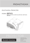
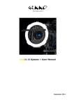
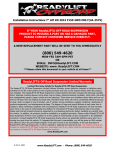
 B-25J Mitchell
RC Airplane KIT
Exclusively for www.scaleflying.com
Manual
FIXED WING RC AIRCRAFT
Super Scale RC Airplane Manual – B-25J
Release 1.0 - Jan 2015
Roban Limited
Zhengyacun Industrial Zone, Venture Cross Rd.
Jiaolian, Wanjiang City District of Dongguan,
523046 Dongguan County (GD) - PRC
Copyright@2015 - Roban Limited – All rights reserved
SPECIFICATIONS
Body length:
Wingspan:
Height:
Dry weight:
Flying weight:
1566mm
2060mm
422mm
4.5kg
6.1-7kg
Motor:*
Speed controller:*
Servo:*
Battery:*
Flight time:
Takeoff weight:
2x 500KV 4020 brushless outrunner, 4-6S capable
2x 60A brushless, 4-6S capable
7x metal gear 40g, 2x metal gear wing mount type
2x 18.5V 4000mAh 35C+
8 minutes
8500g
Radio Control:*
min. 6 channel with flap program
*) Optionally available equipment
Our goal was to create a high scale detail, high performance airplane, with a minimum of assembly work and simple
maintenance.
Please read this user manual carefully, it contains instructions for the correct assembly of the model.
Please refer to the web site www.robanmodel.com for updates and other important information.
Thank you for your purchase, and have a great time with your Airplane!
Roban Limited
Copyright@2015 - Roban Limited – All rights reserved
IMPORTANT NOTES
*This radio controlled airplane is not a toy.
*This radio controlled airplane can be very dangerous.
*This radio controlled airplane is a technically complex device which has to be built and handled very carefully.
*This radio controlled airplane must be built following these instructions. This manual provides the necessary information
to correctly assemble the model. It is necessary to carefully follow all the instructions.
*Inexperienced pilots must be monitored by expert pilots.
*All operators must wear safety glasses and take appropriate safety precautions.
*A radio controlled airplane must only be used in open spaces without obstacles, and far enough from people to
minimize
the possibility of accidents or of injury to property or persons.
*A radio controlled airplane can behave in an unexpected manner, causing loss of control of the model, and make it a
very
dangerous flying object.
*Lack of care with assembly or maintenance can result in an unreliable and dangerous model.
*Neither Roban Limited nor its agents have any control over the assembly, maintenance and use of this product.
Therefore, no
responsibility can be traced back to the manufacturer. You hereby agree to release Roban Limited from any
responsibility or
liability arising from the use of this product.
SAFETY GUIDELINES
*Fly only in areas dedicated to the use of model airplanes.
*Follow all control procedures for the radio frequency system.
*It is necessary that you know your radio system well. Check all functions of the transmitter before every flight.
*The blades of the model rotate at a very high speed; be aware of the danger they pose and the damage they may
cause.
*Never fly in the vicinity of other people.
NOTES FOR ASSEMBLY
Please refer to this manual for assembly instructions for this model.
Follow the order of assembly indicated. The instructions are divided into chapters, which are structured in a way that
each step is based on the work done in the previous step. Changing the order of assembly may result in additional or
unnecessary steps.
Use thread lockers and retaining compounds as indicated. In general, each bolt or screw that engages with a metal part
requires thread lock.
Factory pre-assembled components have been assembled with all the required thread lock and lubricants,
and have passed quality control. It is not necessary to disassemble and re-assemble them.
We do not recommend the use of thin cyanoacrylate glue for surface mount of painted parts. The fumes of the curing
glue leave white stains on the clear coat, which are hard to remove.
Copyright@2015 - Roban Limited – All rights reserved
CONTENTS: 1 – Ball links x16
2 – 5mm Uniball x16
3 – Long Uniball x1
4 – Nut M2 x20
5 – Nut M2.5 x1
6 – Pushrod 2.3x62 x4
7 – Pushrod 2.3x49 x3
8 – Pushrod 2.3x32 x2
9 – Pushrod 2.3x76 x1
10 – Pushrod 2.3x55 x1
11 – L Lever 80/25 x2
12 – L Lever 60/25 x2
13 – T-Junction x2
14 – Servo Disc x1
15 – Servo holder plate x4
16 – Servo holder plate x2
17 – Pin Hinges x4
18 – Hinges x5
19 – Hinges x5
20 – Control horns x4
21 – Control horn washer x6
22 – Screw M2x7 x6
23 – Control horn x6
24 – Screw M3x25 x4
25 – Screw M3x18 x3
26 – Control horn part x6
27 – Control horn part x6
28 – Control clevis x6
29 – Pushrod keepers x6
30 – Screw M3x22 x2
31 – Washer M3x8 x13
32 – Washer M3x10 x8
33 – Screw M4x45 x2
34 – Screw M3x22 x2
35 – Screw M3x18 x4
36 – Screw M3x14 x8
Copyright@2015 - Roban Limited – All rights reserved
37 – Screw M3x12 x6
38 – Screw M3x30 x1
39 – Screw A3x12 x4
40 – Screw A2x12 x4
41 – Screw A2x5 x6
42 – Screw A2x6 x24
43 – Left aft wheel
44 – Front wheel strut
45 – Right aft wheel
46 – Piano wire 0.5mm x2
47 – Piano wire 0.5mm x1
48 – Wing joiner tube x2
49 – Spinner x2
50 – Left side guns
51 – Right side guns
52 – Engine cover x2
53 – Tail gunner canopy
54 – Top gunner canopy
55 – Bomb door servo
holder
56 – Servo holder x2
57 – Servo latch
58 – LHS Retract mount
59 – LHS Motor mount
60 – RHS Retract mount
61 – RHS Motor mount
62 – Scale part
63 – Scale part
64 – Scale part
65 – Servo mount x2
66 – Servo mount x4
67 – Servo mount x2
68 – Engine cowl mount x8
69 – Front wheel mount
70 – Front wheel rod guide
71 – RHS Firewall
72 – LHS Firewall
Copyright@2015 - Roban Limited – All rights reserved
73 – Scale cockpit
74 – Scale part
75 – Scale part x2
76 – Scale part
77 – Scale part x6
78 – Scale part x3
79 – Scale part
80 – Scale part
81 – Scale part
82 – Scale part
83 – Side windows x2
84 – Prolonging wire
85 – Decal set
ADDITIONAL COMPONENTS
REQUIRED
*Electric Motor:
2x 6S – 500KV 4020 type
*Speed controller:
minimum 60A to be safe
*Batteries: 2x 4-6S 4000mAh
*
*Radio power system
*7 40g metal geared servos
*2 flat type wing mount metal geared servos
*6 channel radio control system on 2.4 GHz
Copyright@2015 - Roban Limited – All rights reserved
TOOLS, LUBRICANTS, ADHESIVES
*Generic pliers
*Hexagonal driver, size 1.5, 2, 2.5, 3, 4mm
*4mm T-Wrench
*5.5mm Socket wrench (for M3 nuts)
*8mm Hex fork wrench (for M5 nuts)
*Medium threadlocker (eg. Loctite 243)
*Strong retaining compound (eg. Loctite 648)
*Spray lubricant (eg. Try-Flow Oil)
*Synthetic grease (eg. Tri-Flow Synthetic Grease)
*Cyanoacrylate adhesive
*Epoxy glue 30 min.
*Soldering equipment (for motor wiring)
STEP 1 HINGING FLAPS AND AILERONS
1. Apply instant CA glue to aileron, outer flap, and pin hinge
Use a rotary tool and 1/16-inch (1.5mm) drill bit to drill a 1/2-inch (12mm) deep hole in the center of each hinge slot.
This provides a tunnel allowing the glue used to secure the hinges to fully penetrate the hinge. Slide the hinges
back into the ailerons and outer flaps and apply CA glue.
2. Install the aileron and outer flaps into the main wing
Slide the aileron and outer flap into position on the wing. Make sure the inboard edge of the flap near the center
of the wing, and the outer tip of the aileron near the wing tip do not bind against the wing. Also make sure the flap
and aileron do not bind against each other.
Copyright@2015 - Roban Limited – All rights reserved
3. Glue aileron and outer flaps into the main wing
Push the aileron/outer flap tight against the wing. Flex the aileron and apply enough thin CA to fully penetrate the
hinge. Apply CA to both the top and bottom of the hinge. Important: Do not use accelerator when hinging. The
CA must be allowed to soak into the hinge for the best possible bond between the hinge and surrounding wood.
4. Check and break in aileron and outer flaps
After the CA has fully cured, gently pull on the wing and aileron to make sure the hinges are secure. If not, re-glue
the hinges.
To break in the hinges, you will need to flex the aileron up and down a number of times.
Copyright@2015 - Roban Limited – All rights reserved
5. Hinging the inner flaps
Use medium grit sandpaper to sand the tipped flap torque rod ends (11). Use rubbing alcohol and a paper towel to
remove any debris from the torque rods. This will aid in strengthening the bond between the flap torque rod and
flap. Enter both torque rods into the wing and join them with the T-Junction (13). Make sure to use Loctite to
secure the set screws, and make sure that both torque rods are aligned in the same plane. Also make sure that
the T-Junction is app. 90 degrees positioned relative to the torque rod plane to allow maximum flap travel before
tightening the screws. Hinging the flaps follows the same procedure as the ailerons, except you will need to apply
30-minute epoxy to the torque rods that enter the flaps.
STEP 2 AILERON AND OUTER FLAP SERVO INSTALLATION (REPEAT 4 TIMES) 1. Remove the servo cover from the wing.
Copyright@2015 - Roban Limited – All rights reserved
2. Mount the servo
Position the aileron servo on the base plate (15) with the servo arm centered. Use a pencil to mark the cover where
the flap servo is positioned. Use 30-minute epoxy to glue the servo mounting blocks (66) to the servo cover. Allow
the epoxy to fully cure before proceeding.
3. Mount the servo
Position the servo between the servo mounting blocks. Make sure the servo is not resting on the servo cover,
which will transfer vibrations to the servo. Use a felt-tipped pen to mark the locations for the servo mounting
screws. Use a drill and 1/16-inch (1.5mm) drill bit to drill the four holes for the servo mounting screws. Apply a few
drops of thin CA into each of the holes to harden the surrounding wood to provide a stronger surface for the screws
to bite into. Mount the servo to the blocks using the hardware provided with the servo.
Copyright@2015 - Roban Limited – All rights reserved
4. Routing the wires
Secure an 18-inch (457mm) servo extension to the servo lead for the aileron. Make sure to secure the servo lead
to the extension using string or a commercially available connector to prevent them from becoming disconnected
inside the wing. Tie a string that has needs to be installed inside the wing to the servo extension. Use the string
to pull the servo leads through the wing and to the opening of the wing panel near the flap servo. You will pull the
flap servo leads and the retract servo leads with this same pull string.
5. Install the servo and the cover
Install the servo mount plate into the wing using screws (42). Then install the servo cover on the wing.
STEP 3 AILERON AND OUTER FLAP LINKAGE INSTALLATION 1. Pushrods
Mount 4 ball links (1) onto one end of 4 pushrods (6). Mount the uniballs (2) onto all four servo horns. Thread the
clevis (28) onto the other end of the pushrods. Thread the bearing holder (26) onto the control horn (23). Attach the
ball link to the servo horn.
Copyright@2015 - Roban Limited – All rights reserved
2. Align Pushrods and mount control horn onto aileron/outer flap
Make sure that the servo is in center position and that the aileron / outer flap is in centered position, too. Align the
pushrod perpendicular to the control surface, then mark the four spots to drill the holes for the retaining screw
with a pencil. Drill a 3mm hole and mount the control rod with screw (24) and washer (21) onto the ailerons / outer
flaps using Loctite.
STEP 4 INNER FLAP SERVO AND LINKAGE INSTALLATION 1. Mount servo
Glue the servo mount (65) as shown onto the center main wing using 30 min epoxy. Mount the servo with the
horn centered using the hardware provided with the servo. Then mount an uniball (2) onto the servo horn. Mount
another uniball on the T-Junction using Loctite. Thread 2 ball links (1) onto the pushrod (7) and connect the servo
horn with the T-Junction.
Copyright@2015 - Roban Limited – All rights reserved
STEP 5 ELECTRIC RETRACT INSTALLATION 1. Install Nacelle Framework and gear doors
Align both motor and landing gear mounts inside the nacelle and glue them in with 30 min. epoxy glue. The install
the landing gear doors as shown.
Copyright@2015 - Roban Limited – All rights reserved
2. Install retract and landing gear
Copyright@2015 - Roban Limited – All rights reserved
Copyright@2015 - Roban Limited – All rights reserved
3. Install front retract steering servo and gear door
Follow the steps as shown below.
Copyright@2015 - Roban Limited – All rights reserved
Copyright@2015 - Roban Limited – All rights reserved
Copyright@2015 - Roban Limited – All rights reserved
Copyright@2015 - Roban Limited – All rights reserved
STEP 6 ELECTRIC MOTOR INSTALLATION AND ENGINE COWL MOUNT 1. Mount Motors to nacelle
Mount the motors to the supplied motor holders (71 RHS marked A) and (72 LHS marked B) with the hardware
supplied with the motors. Then mount the motor holders onto the nacelle’s firewalls with screws (32) and washers
(33) using loctite. Blind nuts are premounted on the other side of the firewall.
Copyright@2015 - Roban Limited – All rights reserved
2. Install and Wire ESCs
Solder any necessary connector to the speed control. Connect the leads between the motor and speed control.
Secure the speed controller to the motor mount using double-sided tape and tie wraps. Route the power lead and
servo lead through the hole in the center of the firewall.
3. Install engine cowl
After installing the engine cowl holders (68) onto the firewall, holes need to be drilled into the cowl so that the
cowl can be secured with screws (42).
Copyright@2015 - Roban Limited – All rights reserved
Finally mount the cowl using the screws (42) onto the nacelle.
Copyright@2015 - Roban Limited – All rights reserved
STEP 7 ENGINE NACELLE INSTALLATION 1. Prepare wiring
Prior to installation, pull the power wires, the throttle servo extension and the retract servo extension through the
wing using a string and out of the center hole. The engine nacelle will need to be close to the wing for the extension
from the throttle servo (speed control) to reach the opening in the wing. Once the extensions have been pulled
through the wing, use tape to keep them from falling back into the wing.
2. Attach engine nacelle
Attach the engine nacelle to the wing using two screws (35) and washers (31) using loctite. The front section of
the nacelle has preinstalled dowels, these must engage before the screws are used to tighten the nacelle to the
wing.
Copyright@2015 - Roban Limited – All rights reserved
STEP 8 WING INSTALLATION 1. Mount wing tubes
Slide the wing tube into one of the wing panels. Slide the remaining panel onto the wing tube (48). The panels
should fit tight against each other.
2. Secure the wing tubes
Drill four 1mm holes into the downward wing surface, exactly where the wing tube end’s are located. Then mount
four self tapping screws (40) into the wing and the tube to secure them.
3. Install main wing onto fuselage
Slide the two front dowel pins into the holes on the fuselage, then use a hex driver to fasten two socket head
screws (33) and washers (30) using Loctite, securing the main wing to the fuselage.
STEP 9 RUDDER AND ELEVATOR INSTALLATION 1. Mount servos
Mounting the rudder servo follows the same procedure as mounting the aileron servo (Section 2: Aileron Servo
Installation, Steps 1 through 5, using servo holder plate (16) and mounting blocks (56) instead). Use a 180 degree
servo arm and remove the excess arm using side cutters. Simply follow those steps to mount the rudder servo to
the rudder servo cover.
Copyright@2015 - Roban Limited – All rights reserved
2. Mount rudder fins
Use 30-minute epoxy to attach the fin to the stabilizer. Note: Make sure the vertical fins remain in alignment
while the epoxy cures.
3. Prepare Rudder
Remove the elevators and rudders from the stabilizer and fins and set aside the CA hinges. Use a rotary tool and
1/16-inch (1.5mm) drill bit to drill a 1/2-inch (12mm) deep hole in the center of each hinge slot for the rudders and
fins. This provides a tunnel allowing the glue used to secure the hinges to fully penetrate the hinge. Note: Drill the
holes in the hinge slots for the elevators and stabilizer at this time as well.
Copyright@2015 - Roban Limited – All rights reserved
4. Mount rudder
Slide the rudder into position on the fin. Make sure the rudder can move without binding against the fin at the top
and bottom. Flex the rudder and apply enough thin CA to fully penetrate the hinge. Apply CA to both sides of the
hinge. Important: Do not use accelerator when hinging. The CA must be allowed to soak into the hinge for the
best possible bond between the hinge and surrounding wood.
5. Check and break in hinges
After the CA has fully cured, gently pull on the rudder and fin to make sure the hinges are secure. If not, re-glue
the hinges. To break in the hinges, you will need to flex the rudder back and forth a number of times.
Copyright@2015 - Roban Limited – All rights reserved
6. Mount elevator
Use medium grit sandpaper to sand the tipped flap torque rod ends (12). Use rubbing alcohol and a paper towel to
remove any debris from the torque rods. This will aid in strengthening the bond between the flap torque rod and
flap. Enter both torque rods into the wing and join them with the T-Junction (13). Make sure to use Loctite to
secure the set screws, and make sure that both torque rods are aligned in the same plane. Also make sure that
the T-Junction is app. 90 degrees positioned relative to the torque rod plane to allow maximum flap travel before
tightening the screws. Hinging the flaps follows the same procedure as the ailerons, except you will need to apply
30-minute epoxy to the torque rods that enter the flaps.
STEP 10 RUDDER AND ELEVATOR SERVO INSTALLATION 1. Mount elevator servo
Glue the servo mount (65) as shown onto the center main wing using 30 min epoxy. Mount the servo with the
horn centered using the hardware provided with the servo. Then mount an uniball (2) onto the servo horn. Mount
another uniball on the T-Junction using Loctite. Thread 2 ball links (1) onto the pushrod (7) and connect the servo
horn with the T-Junction.
Copyright@2015 - Roban Limited – All rights reserved
2. Pushrods
Mount 2 ball links (1) onto one end of 2 pushrods (6). Mount the uniballs (2) onto the two servo horns. Thread the
clevis (28) onto the other end of the pushrods. Thread the bearing holder (26) onto the control horn (23). Attach the
ball link to the servo horn.
3. Align Pushrods and mount control horn onto aileron/outer flap
Make sure that the servo is in center position and that the rudder is in centered position, too. Position the control
horn on the fin so it won't interfere with the elevator, and so it is in alignment with the rudder servo arm. Mark the
location for the mounting screw on the rudder with a pencil. Drill a 3mm hole and mount the control rod with screw
(24) and washer (21) onto the rudders using Loctite.
Copyright@2015 - Roban Limited – All rights reserved
STEP 11 TAIL SECTION INSTALLATION 1. Servo wires
Connect the Y-harness and 24-inch (610mm) servo extension to the rudder servos and pass them into the radio
compartment. Make sure to secure all connections so they will not become unplugged inside the fuselage.
2. Secure stabilizer
Secure the stabilizer using a hex driver, two socket head screws (34) and washers (31) using loctite.
Copyright@2015 - Roban Limited – All rights reserved
STEP 12 SCALE ACCESSORIES 1. Bombardiers cockpit
Follow the steps as shown below.
Copyright@2015 - Roban Limited – All rights reserved
Copyright@2015 - Roban Limited – All rights reserved
2. Cockpit
Follow the steps as shown below.
Copyright@2015 - Roban Limited – All rights reserved
Copyright@2015 - Roban Limited – All rights reserved
Copyright@2015 - Roban Limited – All rights reserved
Copyright@2015 - Roban Limited – All rights reserved
3. Top gunner
Follow the steps as shown below.
Copyright@2015 - Roban Limited – All rights reserved
4. Tail gunner
Follow the steps as shown below.
Copyright@2015 - Roban Limited – All rights reserved
Copyright@2015 - Roban Limited – All rights reserved
5. Side windows
Follow the steps as shown below.
Copyright@2015 - Roban Limited – All rights reserved
6. Bomb bay
Follow the steps as shown below.
Copyright@2015 - Roban Limited – All rights reserved
7.
Copyright@2015 - Roban Limited – All rights reserved
Copyright@2015 - Roban Limited – All rights reserved
Copyright@2015 - Roban Limited – All rights reserved
STEP 13 CENTER OF GRAVITY 1. Recommended CG
An important part of preparing the aircraft for flight is properly balancing the model. This is especially important
when various engines are mounted. Caution: Do not inadvertently skip this step! The recommended Center of
Gravity (CG) location for the B-25 Mitchell is 3 3/4-in (95.25mm) behind the leading edge of the wing against the
fuselage. Mark the location of the CG on the bottom of the wing as shown. Turn the airframe upright to balance.
If necessary, move the battery pack or add weight to either the nose or the tail until the correct balance is achieved.
Stick-on weights are available at your local hobby store and work well for this purpose.
STEP 14 CONTROL THROWS 1. Note on control throws
The amount of control throw should be adjusted as closely as possible using mechanical means, rather than making
large changes electronically at the radio. By moving the position of the clevis at the control horn toward the
outermost hole, you will decrease the amount of control throw of the control surface. Moving it toward the control
surface will increase the amount of throw. Moving the pushrod wire at the servo arm will have the opposite effect:
Moving it closer to center will decrease throw, and away from center will increase throw. Work with a combination
of the two to achieve the closest or exact control throws listed.
2.
Control throws Elevator Low Rate 7 degrees, 3/8‐inch or 8.5mm up/down Elevator High Rate 13 degrees, 5/8‐inch or 16mm up/down Note: Elevator throw is measured at inboard end of elevator. Rudder Low Rate Copyright@2015 - Roban Limited – All rights reserved
10 degrees, 1/2‐inch or 13mm right/left Rudder High Rate 16 degrees, 13/16‐inch or 21mm right/left Note: Rudder throw is measured at the widest part of the rudder. Aileron Low Rate 10 degrees, 3/8‐inch or 9.5mm up/down Aileron High Rate 15 degrees, 9/16‐inch or 14mm up/down Note: Aileron throw is measured at inboard end of aileron. Half Flap Position 20 degrees,1‐inch or 26mm down Full Flap Position 40 degrees, 1 15/16‐inch or 49mm down Note: Flap throw is measured at end of flap against the fuselage. STEP 15 RANGE TEST YOUR RADIO 1. Perform range check
Range check your radio system before each flying session. This is accomplished by turning on your transmitter
with the antenna collapsed. Turn on the radio in your airplane. With your airplane on the ground, you should be able
to walk 30 paces away from your airplane and still have complete control of all functions. If not, don’t attempt to
fly! Have your radio equipment checked out by the manufacturer.
STEP 16 PRE‐FLIGHT 1. Preparations
Charge both the transmitter and receiver pack for your airplane. Use the recommended charger supplied with your
particular radio system, following the instructions provided with the radio. In most cases, the radio should be
charged the night before going out flying.
Check the radio installation and make sure all the control surfaces are moving correctly (i.e. the correct direction
and with the recommended throws). Test run the engine and make sure it transitions smoothly from idle to full
throttle and back. Also ensure the engine is tuned according to the manufacturer’s instructions,and it will run
consistently and constantly at full throttle when adjusted.
Check all the control horns, servo horns and clevises to make sure they are secure and in good condition. Replace
any items that would be considered questionable. Failure of any of these components in flight would mean the
loss of your aircraft.
STEP 17 TAKEOFF 1. Notes on takeoff
Prior to your first flight we recommend that you do some low speed taxi tests. Use these tests to center the nose
wheel steering to allow for a takeoff straight down the runway. Once you have finished this be sure and take a
minute to change the batteries and take one last look at the airframe to be sure all screws and control linkages are
Copyright@2015 - Roban Limited – All rights reserved
secure. The flaps are not needed if you are taking off from a hard packed runaway such as asphalt and even fields
with short grass do not require the use of flaps. If you are taking off from a grass field that is rough or has not been
mowed recently, then we recommend that you use the half flap position and allow a little extra takeoff roll before
gradually feeding in up elevator. Once you have the B-25 airborne maintain a shallow rate of climb and allow the
model to gain speed prior to making the first turn. The flaps should be retracted at this point and you should be
entering into the normal traffic pattern. If you are using retracts then we suggest that you retract the landing gear
prior to retracting the flaps. Familiarize yourself with the flight characteristics of the B-25 and practice flying the
model at a safe height using both the mid and full flap positions. Be sure and reduce the throttles and allow the B25 to slow a bit prior to lowering the flaps to the first or mid position. Then lower the flaps to the full position and
adjust power to maintain straight and level flight. You will find that the B-25 does not balloon or pitch up if you
allow the model to slow prior to dropping the flaps. We have found that if you follow this procedure, then you will
not need to mix in any down elevator compensation.
STEP 18 LANDING 1. Notes on landing
To begin the landing approach you will need to first lower the throttles and reduce your flight speed. We
recommend this take place on the downwind leg and that you have the flaps in the full down position prior to
beginning your turn to the base leg. Allow the B-25 to begin a slow downward decent and gradually allow the
airspeed to bleed off. The idea is to loose altitude and maintain airspeed by keeping the nose down in the turn. As
you begin your upwind approach use the throttles to maintain your sink rate and as you pass over the end of the
runway reduce the throttles to idle and begin to add up elevator and begin your flare to landing. Should you
overshoot the landing the gradually add power and use the rudders to keep the B-25 on track. Keep the flaps in the
full down position and begin to set up for a second attempt.
2007 OFFICIAL AMA NATIONAL MODEL AIRCRAFT SAFETY CODE GENERAL
1. A model aircraft shall be defined as a non-human carrying device capable of sustained flight in the atmosphere.
It shall not exceed limitations established in this code and is intended to be used exclusively for recreational or
competition activity.
2. The maximum takeoff weight of a model aircraft, including fuel, is 55 pounds, except for those flown under
the AMA Experimental Aircraft Rules.
3. I will abide by this Safety Code and all rules established for the flying site I use. I will not willfully fly my model
aircraft in a reckless and/or dangerous manner.
4. I will not fly my model aircraft in sanctioned events, air shows, or model demonstrations until it has been
proven airworthy.
5. I will not fly my model aircraft higher than approximately 400 feet above ground level, when within three (3)
miles of an airport without notifying the airport operator. I will yield the right-of-way and avoid flying in the
proximity of full-scale aircraft, utilizing a spotter when appropriate.
6. I will not fly my model aircraft unless it is identified with my name and address, or AMA number, inside or
affixed to the outside of the model aircraft. This does not apply to model aircraft flown indoors.
7. I will not operate model aircraft with metal-blade propellers or with gaseous boosts (other than air), nor will I
operate model aircraft with fuels containing tetranitromethane or hydrazine.
8. I will not operate model aircraft carrying pyrotechnic devices which explode burn, or propel a projectile of any
kind. Exceptions include Free Flight fuses or devices that burn producing smoke and are securely attached to
Copyright@2015 - Roban Limited – All rights reserved
9.
10.
11.
12.
the model aircraft during flight. Rocket motors up to a G-series size may be used, provided they remain firmly
attached to the model aircraft during flight. Model rockets may be flown in accordance with the National Model
Rocketry Safety Code; however, they may not be launched from model aircraft. Officially designated AMA Air
Show Teams (AST) are authorized to use devices and practices as defined within the Air Show Advisory
Committee Document.
I will not operate my model aircraft while under the influence of alcohol or within eight (8) hours of having
consumed alcohol.
I will not operate my model aircraft while using any drug which could adversely affect my ability to safely
control my model aircraft.
Children under six (6) years old are only allowed on a flightline or in a flight area as a pilot or while under flight
instruction.
When and where required by rule, helmets must be properly worn and fastened. They must be OSHA, DOT,
ANSI, SNELL or NOCSAE approved or comply with comparable standards.
Radio Control
1. All model flying shall be conducted in a manner to avoid over flight of unprotected people. I will have completed
a successful radio equipment ground-range check before the first flight of a new or repaired model aircraft.
2. I will not fly my model aircraft in the presence of spectators until I become a proficient flier, unless I am assisted
by an experienced pilot.
3. At all flying sites a line must be established, in front of which all flying takes place. Only personnel associated
with flying the model aircraft are allowed at or in front of the line. In the case of airshows demonstrations
straight line must be established. An area away from the line must be maintained for spectators. Intentional
flying behind the line is prohibited.
4. I will operate my model aircraft using only radio control frequencies currently allowed by the Federal
Communications Commission (FCC). Only individuals properly licensed by the FCC are authorized to operate
equipment on Amateur Band frequencies.
5. I will not knowingly operate my model aircraft within three (3) miles of any preexisting flying site without a
frequency-management agreement. A frequency management agreement may be an allocation of frequencies
for each site, a day-use agreement between sites, or testing which determines that no interference exists. A
frequency-management agreement may exist between two or more AMA chartered clubs, AMA clubs and
individual AMA members, or individual AMA members. Frequency-management agreements, including an
interference test report if the agreement indicates no interference exists, will be signed by all parties and
copies provided to AMA Headquarters.
6. With the exception of events flown under official AMA rules, no powered model may be flown outdoors closer
than 25 feet to any individual, except for the pilot and located at the flight line.
7. Under no circumstances may a pilot or other person touch a model aircraft in flight while it is still under power,
except to divert it from striking an individual.
8. Radio-controlled night flying is limited to low performance model aircraft (less than 100 mph). The model aircraft
must be equipped with a lighting system which clearly defines the aircraft's attitude and direction at all times.
9. The operator of a radio-controlled model aircraft shall control it during the entire flight, maintaining visual contact
without enhancement other than by corrective lenses that are prescribed for the pilot. No model aircraft shall
be equipped with devices which allow it to be flown to a selected location which is beyond the visual range of
the pilot.
Copyright@2015 - Roban Limited – All rights reserved
NOTES:
Copyright@2015 - Roban Limited – All rights reserved
www.robanmodel.com
Copyright@2015 - Roban Limited – All rights reserved